JP4164227B2 - Data receiving apparatus and method, and storage medium - Google Patents
Data receiving apparatus and method, and storage medium Download PDFInfo
- Publication number
- JP4164227B2 JP4164227B2 JP2000351992A JP2000351992A JP4164227B2 JP 4164227 B2 JP4164227 B2 JP 4164227B2 JP 2000351992 A JP2000351992 A JP 2000351992A JP 2000351992 A JP2000351992 A JP 2000351992A JP 4164227 B2 JP4164227 B2 JP 4164227B2
- Authority
- JP
- Japan
- Prior art keywords
- data
- receiving
- display
- unit
- Prior art date
- Legal status (The legal status is an assumption and is not a legal conclusion. Google has not performed a legal analysis and makes no representation as to the accuracy of the status listed.)
- Expired - Fee Related
Links
Images


Classifications
-
- H—ELECTRICITY
- H04—ELECTRIC COMMUNICATION TECHNIQUE
- H04N—PICTORIAL COMMUNICATION, e.g. TELEVISION
- H04N21/00—Selective content distribution, e.g. interactive television or video on demand [VOD]
- H04N21/40—Client devices specifically adapted for the reception of or interaction with content, e.g. set-top-box [STB]; Operations thereof
- H04N21/47—End-user applications
- H04N21/472—End-user interface for requesting content, additional data or services; End-user interface for interacting with content, e.g. for content reservation or setting reminders, for requesting event notification, for manipulating displayed content
- H04N21/4722—End-user interface for requesting content, additional data or services; End-user interface for interacting with content, e.g. for content reservation or setting reminders, for requesting event notification, for manipulating displayed content for requesting additional data associated with the content
-
- H—ELECTRICITY
- H04—ELECTRIC COMMUNICATION TECHNIQUE
- H04N—PICTORIAL COMMUNICATION, e.g. TELEVISION
- H04N21/00—Selective content distribution, e.g. interactive television or video on demand [VOD]
- H04N21/40—Client devices specifically adapted for the reception of or interaction with content, e.g. set-top-box [STB]; Operations thereof
- H04N21/41—Structure of client; Structure of client peripherals
- H04N21/4104—Peripherals receiving signals from specially adapted client devices
- H04N21/4117—Peripherals receiving signals from specially adapted client devices for generating hard copies of the content, e.g. printer, electronic paper
-
- H—ELECTRICITY
- H04—ELECTRIC COMMUNICATION TECHNIQUE
- H04N—PICTORIAL COMMUNICATION, e.g. TELEVISION
- H04N21/00—Selective content distribution, e.g. interactive television or video on demand [VOD]
- H04N21/40—Client devices specifically adapted for the reception of or interaction with content, e.g. set-top-box [STB]; Operations thereof
- H04N21/43—Processing of content or additional data, e.g. demultiplexing additional data from a digital video stream; Elementary client operations, e.g. monitoring of home network or synchronising decoder's clock; Client middleware
- H04N21/431—Generation of visual interfaces for content selection or interaction; Content or additional data rendering
- H04N21/4312—Generation of visual interfaces for content selection or interaction; Content or additional data rendering involving specific graphical features, e.g. screen layout, special fonts or colors, blinking icons, highlights or animations
-
- H—ELECTRICITY
- H04—ELECTRIC COMMUNICATION TECHNIQUE
- H04N—PICTORIAL COMMUNICATION, e.g. TELEVISION
- H04N21/00—Selective content distribution, e.g. interactive television or video on demand [VOD]
- H04N21/40—Client devices specifically adapted for the reception of or interaction with content, e.g. set-top-box [STB]; Operations thereof
- H04N21/43—Processing of content or additional data, e.g. demultiplexing additional data from a digital video stream; Elementary client operations, e.g. monitoring of home network or synchronising decoder's clock; Client middleware
- H04N21/434—Disassembling of a multiplex stream, e.g. demultiplexing audio and video streams, extraction of additional data from a video stream; Remultiplexing of multiplex streams; Extraction or processing of SI; Disassembling of packetised elementary stream
- H04N21/4345—Extraction or processing of SI, e.g. extracting service information from an MPEG stream
-
- H—ELECTRICITY
- H04—ELECTRIC COMMUNICATION TECHNIQUE
- H04N—PICTORIAL COMMUNICATION, e.g. TELEVISION
- H04N21/00—Selective content distribution, e.g. interactive television or video on demand [VOD]
- H04N21/40—Client devices specifically adapted for the reception of or interaction with content, e.g. set-top-box [STB]; Operations thereof
- H04N21/43—Processing of content or additional data, e.g. demultiplexing additional data from a digital video stream; Elementary client operations, e.g. monitoring of home network or synchronising decoder's clock; Client middleware
- H04N21/434—Disassembling of a multiplex stream, e.g. demultiplexing audio and video streams, extraction of additional data from a video stream; Remultiplexing of multiplex streams; Extraction or processing of SI; Disassembling of packetised elementary stream
- H04N21/4348—Demultiplexing of additional data and video streams
-
- H—ELECTRICITY
- H04—ELECTRIC COMMUNICATION TECHNIQUE
- H04N—PICTORIAL COMMUNICATION, e.g. TELEVISION
- H04N21/00—Selective content distribution, e.g. interactive television or video on demand [VOD]
- H04N21/40—Client devices specifically adapted for the reception of or interaction with content, e.g. set-top-box [STB]; Operations thereof
- H04N21/43—Processing of content or additional data, e.g. demultiplexing additional data from a digital video stream; Elementary client operations, e.g. monitoring of home network or synchronising decoder's clock; Client middleware
- H04N21/435—Processing of additional data, e.g. decrypting of additional data, reconstructing software from modules extracted from the transport stream
- H04N21/4355—Processing of additional data, e.g. decrypting of additional data, reconstructing software from modules extracted from the transport stream involving reformatting operations of additional data, e.g. HTML pages on a television screen
-
- H—ELECTRICITY
- H04—ELECTRIC COMMUNICATION TECHNIQUE
- H04N—PICTORIAL COMMUNICATION, e.g. TELEVISION
- H04N21/00—Selective content distribution, e.g. interactive television or video on demand [VOD]
- H04N21/40—Client devices specifically adapted for the reception of or interaction with content, e.g. set-top-box [STB]; Operations thereof
- H04N21/41—Structure of client; Structure of client peripherals
- H04N21/422—Input-only peripherals, i.e. input devices connected to specially adapted client devices, e.g. global positioning system [GPS]
- H04N21/42204—User interfaces specially adapted for controlling a client device through a remote control device; Remote control devices therefor
- H04N21/42206—User interfaces specially adapted for controlling a client device through a remote control device; Remote control devices therefor characterized by hardware details
- H04N21/4221—Dedicated function buttons, e.g. for the control of an EPG, subtitles, aspect ratio, picture-in-picture or teletext
-
- H—ELECTRICITY
- H04—ELECTRIC COMMUNICATION TECHNIQUE
- H04N—PICTORIAL COMMUNICATION, e.g. TELEVISION
- H04N21/00—Selective content distribution, e.g. interactive television or video on demand [VOD]
- H04N21/40—Client devices specifically adapted for the reception of or interaction with content, e.g. set-top-box [STB]; Operations thereof
- H04N21/41—Structure of client; Structure of client peripherals
- H04N21/426—Internal components of the client ; Characteristics thereof
- H04N21/42676—Internal components of the client ; Characteristics thereof for modulating an analogue carrier signal to encode digital information or demodulating it to decode digital information, e.g. ADSL or cable modem
-
- H—ELECTRICITY
- H04—ELECTRIC COMMUNICATION TECHNIQUE
- H04N—PICTORIAL COMMUNICATION, e.g. TELEVISION
- H04N21/00—Selective content distribution, e.g. interactive television or video on demand [VOD]
- H04N21/40—Client devices specifically adapted for the reception of or interaction with content, e.g. set-top-box [STB]; Operations thereof
- H04N21/45—Management operations performed by the client for facilitating the reception of or the interaction with the content or administrating data related to the end-user or to the client device itself, e.g. learning user preferences for recommending movies, resolving scheduling conflicts
- H04N21/462—Content or additional data management, e.g. creating a master electronic program guide from data received from the Internet and a Head-end, controlling the complexity of a video stream by scaling the resolution or bit-rate based on the client capabilities
- H04N21/4622—Retrieving content or additional data from different sources, e.g. from a broadcast channel and the Internet
-
- H—ELECTRICITY
- H04—ELECTRIC COMMUNICATION TECHNIQUE
- H04N—PICTORIAL COMMUNICATION, e.g. TELEVISION
- H04N21/00—Selective content distribution, e.g. interactive television or video on demand [VOD]
- H04N21/80—Generation or processing of content or additional data by content creator independently of the distribution process; Content per se
- H04N21/85—Assembly of content; Generation of multimedia applications
- H04N21/854—Content authoring
- H04N21/8543—Content authoring using a description language, e.g. Multimedia and Hypermedia information coding Expert Group [MHEG], eXtensible Markup Language [XML]
Description
【0001】
【発明の属する技術分野】
本発明は、データ受信装置及び方法、及び記憶媒体に関し、例えば文字、画像、音声、映像等が多重化されたデータ放送コンテンツを受信し表示及び再生を行うデータ放送受信対応テレビ放送受像機におけるデータ処理に適用する場合に好適なデータ受信装置及び方法、及び記憶媒体に関する。
【0002】
【従来の技術】
従来、データ放送は、地上波テレビ放送での運用が行われ、衛星デジタル放送においても本格的に放送が開始されようとしている。これらのデータ放送は、いずれも放送局からデータを放送電波に重畳して放送するものである。受信端末側では、放送電波を受信し蓄積したデータをパーソナルコンピュータ(以下パソコン)や専用端末に読み込み、汎用WWW(World Wide Web)ブラウザソフトや専用ブラウザソフトで表示するものである。
【0003】
昨今、上記のようなデータ放送サービスを、パソコンだけでなくテレビ受像機でも受信可能とすることにより、新たなサービスの提供が期待されている。即ち、テレビ受像機自体にデータ放送の受信機能並びにブラウザソフトを搭載することにより、パソコンを持たないユーザでも手軽に様々な情報を閲覧できるようになり、テレビ番組と連動した情報を文字や画像で表示させるサービスが提供できるようになる。
【0004】
一例としてデータ放送を利用した新しいニュースサービスが提案されている。これは、テレビ受像機側の蓄積装置に予めニュース映像などを記録しておき、文字や画像からなるデータ放送画面を「ニュース項目」としてユーザに提示し、リモコンなどを介してユーザが選択したニュース項目の映像を再生するといったものである。このようなサービスにより、従来は決められた時間にしか視聴できなかったニュース番組がいつでも視聴できるようになったり、ユーザが視聴したいニュースの項目だけが視聴できるようになるなど、従来に無かった新しいサービスが提供できるようになる。
【0005】
【発明が解決しようとする課題】
しかしながら、上述した従来技術においては下記のような問題があった。即ち、上述したようなデータ放送の受信機能をテレビ受像機に持たせた場合、文字の視認性を高めるために、通常、大き目のフォントが使用される。その結果、当然ながら一度に表示できる文字情報が少なくなり、例えば上述のニュースサービスにおいては、ニュースコンテンツを3つ乃至5つ分、画面に表示するのがやっとであり、たくさんのニュース項目を要約と写真と共に表示することが困難であった。
【0006】
また、スクロールやページ切り替えなどによって、一度に表示しきれなかった情報を表示する手段も考えられるものの、ユーザに不要な操作を強いるものであり、パソコンやテレビゲームなどの操作環境に慣れていないユーザのことを考えれば適当とは言えない。
【0007】
また、放送されている映像番組放送やデータ放送の有益な内容を、プリンタにより紙に印刷した後で見るようにすることで、ユーザにとって利便性が向上する。その場合、テレビ受像機をビデオプリンタと接続し、テレビ受像機の表示画面をキャプチャし、印刷することも考えられるが、上述した通り、文字の視認性を高めるために、通常、大き目のフォントが使用されるため、必然的に印刷される文字も大きなものとなってしまい、テレビ画面と比較して、一般的に文字の視認性が高い紙の利点を活かせなくなってしまうという問題点がある。
【0008】
そこで、以上の問題を解消するために、映像番組放送やデータ放送におけるテレビ受像機表示用のデータと共に、それら放送に関連した、より詳細な画像データ、文字データ等の印刷用データを重畳して放送し、印刷時にはそのデータを用いて印刷させることも考えられるが、その場合には、以下のような要望が出てくる可能性がある。
【0009】
(1)映像、データ放送番組視聴中に、いつ印刷データが送出されているか、ユーザには分からない場合もあるため、いつ印刷データが送出されているかをユーザが明確に認識できるようにすれば都合がよい。
【0010】
(2)映像、データ放送番組視聴中に、どのような種類の印刷データが送出されているのかどうか、ユーザには分からない場合もあるため、どのような種類の印刷データが送出されているのかをユーザが明確に認識できるようにすれば都合がよい。
【0011】
(3)印刷するとどれくらいのボリュームになるのか、ユーザには分からない場合もあるため、印刷するとどれくらいのボリュームになるのかをユーザが明確に認識できるようにすれば都合がよい。
【0012】
本発明は、上述した点に鑑みなされたものであり、データが伝送されているにも関わらず、印刷できない、印刷できなかったといった事態の発生を防止すると共に、ユーザがプリンタの紙の種類や枚数等を正確に事前準備できるようにしたデータ受信装置及び方法、及び記憶媒体を提供することを目的とする。
【0013】
【課題を解決するための手段】
上記目的を達成するため、本願発明に係るデータ受信装置は、データ受信装置であって、放送番組の映像データ、前記放送番組に関連する印刷用データ、及び前記印刷用データの属性を示す印刷付加情報が多重化して送信されたテレビジョン放送データを受信する受信手段と、前記受信手段により受信されたテレビジョン放送データから前記印刷付加情報を取得する取得手段と、前記取得手段で取得された前記印刷付加情報の内容を示す表示データを、前記受信手段により受信された前記テレビジョン放送データに含まれる前記映像データとともに表示部に表示させる表示制御手段とを備え、前記印刷付加情報は、前記印刷用データを印刷する用紙のサイズを示す情報と、前記印刷用データを印刷する用紙の枚数を示す情報と、前記印刷用データの種別を示す情報と、前記印刷用データが送信される時間を特定するための時間情報のうちの少なくとも一つの情報を含むことを特徴とする。
【0014】
また、本願発明に係るデータ受信方法は、データ受信方法であって、放送番組の映像データ、前記放送番組に関連する印刷用データ、及び前記印刷用データの属性を示す印刷付加情報が多重化して送信されたテレビジョン放送データを受信する受信ステップと、前記受信ステップで受信されたテレビジョン放送データから前記印刷付加情報を取得する取得ステップと、前記取得ステップで取得された前記印刷付加情報の内容を示す表示データを、前記受信ステップで受信された前記テレビジョン放送データに含まれる前記映像データとともに表示部に表示させる表示制御ステップとを有し、前記印刷付加情報は、前記印刷用データを印刷する用紙のサイズを示す情報と、前記印刷用データを印刷する用紙の枚数を示す情報と、前記印刷用データの種別を示す情報と、前記印刷用データが送信される時間を特定するための時間情報のうちの少なくとも一つの情報を含むことを特徴とする。
【0015】
また、本願発明に係る記憶媒体は、上記データ受信方法の動作をコンピュータに実行させるためのプログラムを記憶したコンピュータ読取可能な記憶媒体であることを特徴とする。
【0077】
【発明の実施の形態】
先ず、本発明の実施の形態を説明する前に、本発明の概要について説明する。本発明は、デジタル放送波にプリント可能なコンテンツデータが含まれていた場合、映像番組やデータ放送番組を表示中のデジタルテレビ受信装置の画面上にメッセージ、マーク、アイコンを表示し、また、音声メッセージを出力することにより、ユーザに分かり易くその旨を報知するものである。以下、本発明の実施の形態を図面に基づいて詳細に説明する。
【0078】
[第1の実施の形態]
図1は本発明の第1実施形態に係るデジタルテレビ受信装置の全体構成を示すブロック図である。本発明の第1実施形態に係るデジタルテレビ受信装置は、チューナ部101、デスクランブラ102、デマルチプレクサ103、ビデオデコーダ104、オーディオデコーダ105、データストリーム処理部106、メモリ107、画面構成部108、表示制御部109、音声制御部110、画像表示部112、音声出力部113、操作部114、受光部115、ICカード制御部117、CPU118、バス120、モデム121、IEEE1394インタフェース122を備えている。図中、符号116で示すものはリモコン、符号132で示すものはプリンタである。
【0079】
上記構成を動作と共に詳述すると、デジタルテレビ受信装置100において、不図示のアンテナにより受信された信号は、チューナ部101に入力される。(ここで、不図示のアンテナ及びチューナ部101は受信手段に相当する。)チューナ部101は、入力された信号に対して、復調、誤り訂正等の処理を施し、トランスポートストリームと呼ばれる形式のデジタルデータを生成する。更に、生成したトランスポートストリーム(TS)データをデスクランブラ102に出力する。
【0080】
デスクランブラ102は、視聴制限のためのスクランブルがかけられているTSデータがチューナ部101より入力された場合、ICカード制御部117において生成されるデスクランブルのための鍵情報に基づき、スクランブルの解除を行う。ここで、ICカード制御部117は、ユーザの契約情報、及びTSデータに含まれるデスクランブラ用の鍵情報を解くための鍵情報が格納されているICカードを有する。また、デスクランブラ102は、チューナ部101よりスクランブルがかけられていないTSデータを入力した場合には、TSデータをそのままデマルチプレクサ103に出力する。
【0081】
デマルチプレクサ103は、デスクランブラ102より入力された複数チャンネル分の映像データ、音声データ、電子番組ガイド(EPG)データ、データ放送データ、プリントコンテンツデータ等が時分割多重されているTSデータの中から、映像・音声・EPGデータ/データ放送データ/プリントコンテンツデータを夫々識別し、取り出しを行う。TSデータは、パケット単位で伝送され、パケットの先頭部分にはPID(Packet Identifier)が付与されている。
【0082】
デマルチプレクサ103は、このPIDを読み取ることで、TSデータの中から必要な映像データD1、音声データD2、EPG/データ放送/プリントコンテンツデータD3の各データを含むTSパケットの識別、取り出しを行う。また、デマルチプレクサ103は、TSデータに含まれるPAT(Program Association Table)を取り出し、取得したPATをバス120を介しCPU118に送出する(ここで、デマルチプレクサ103は、取得手段に相当する)。
【0083】
CPU118は、PATを解析することにより、所望のチャンネルに係るPMT(Program Map Table)のPIDを認識する。その後、CPU118は、デマルチプレクサ103に対し所望のPMTの取得要求を行う。デマルチプレクサ103は、その要求に従い、TSデータに含まれる所望のPMTを取り出し、バス120を介しCPU118に、取得したPMTを送出する。CPU118は、PMTを解析することにより、所望のチャンネルに係る映像、音声、データ放送データ/プリントコンテンツデータを含むTSパケットのPIDや、映像、音声、データ放送データ/プリントコンテンツデータに関する付属情報を得る。
【0084】
図2及び図3は本発明の第1の実施の形態に係る検証、説明を行うために試用したTSデータに挿入したPMTの一例を示す説明図である。
【0085】
図2の▲1▼で示す部分は、ISO/IEC 13818−1記載事項によるものと同様で、PMTセクションのヘッダ部分を示すもので、詳細は省略するが、PMTのデータ長を認識するための情報やチャンネル番号が記載されている。
【0086】
図2の▲2▼で示す部分は、ISO/IEC 13818−1記載事項によるものと同様で、詳細は省略するが、PCR(Program Clock Reference)の値を含むTSパケットのPID等の情報が記載されている。
【0087】
図2の▲3▼で示す部分は、ISO/IEC 13818−1、社団法人電波産業会(通称ARIB)における技術資料「BSデジタル放送運用規定」等の記載事項によるものと同様で、該当するチャンネルの番組を構成する映像ES(Elementary Stream)についての記述がなされている。尚、stream_type = 0x02 は、ISO/IEC 13818−2で規定される映像ストリームであることを示している。上記映像ESを含むTSパケットのPIDは、elementary_PIDの部分に記述される。stream_identifier_descriptor中に記述されるcomponent_tag = 0x00は、この映像ESが現在受信中のチャンネルにおけるデフォルトESであることを示している。
【0088】
図2の▲4▼で示す部分は、ISO/IEC 13818−1、社団法人電波産業会(通称ARIB)における技術資料「BSデジタル放送運用規定」等の記載事項によるものと同様で、該当するチャンネルの番組を構成する音声ES(Elementary Stream)についての記述がなされている。尚、stream_type=0x0F は、ISO/IEC 13818−7で規定される音声ストリームであることを示している。上記音声ES を含むTSパケットのPIDは、elementary_PIDの部分に記述される。stream_identifier_descriptor中に記述されるcomponent_tag = 0x10は、この音声ESが現在受信中のチャンネルにおけるデフォルトESであることを示している。
【0089】
図3の▲5▼で示す部分は、ISO/IEC 13818−1、社団法人電波産業会(通称ARIB)における技術資料「BSデジタル放送運用規定」等の記載事項によるものと同様で、該当するチャンネルに含まれるデータ放送コンテンツについての記述がなされている。尚、stream_type=0x0D は、ISO/IEC 13818−6で規定されるデータカルーセルであることを示している。上記データ放送コンテンツを含むTSパケットのPIDは、elementary_PIDの部分に記述される。stream_identifier_descriptor中に記述されるcomponent_tag = 0x40は、このデータ放送コンテンツが現在受信中のチャンネルにおけるデフォルトコンテンツであることを示している。data_component_descriptorは、社団法人電波産業会(通称ARIB)における標準規格「ARIB STD-B10 BSデジタル放送に使用する番組配列情報」、「ARIB STD-B24デジタル放送におけるデータ放送符号化方式と伝送方式」等に記述されており、データ符号化方式を識別するために使用される。本descriptor(記述子)に記述されるdata_component_idは、データ符号化方式を識別するために使用され、data_component_id = 0x0007は、ARIB-XMLベースマルチメディア符号化方式であることを示している。図3の▲6▼で示す部分は、後述する。
【0090】
上述したPMT記載の情報に従い、デマルチプレクサ103は、現在放送中の番組に係る映像データD1、及び音声データD2を取り出し、それぞれをビデオデコーダ104及びオーディオデコーダ105に出力する。また、デマルチプレクサ103は、上述のTSデータよりEPGデータ/データ放送データ/プリントコンテンツデータD3を取り出し、データストリーム処理部106に入力する。
【0091】
先ず、映像データD1について説明する。ビデオデコーダ104は、デマルチプレクサ103より入力された映像データD1に対して、MPEG2のデコード処理を施し、復号した映像データを表示制御部109に出力する。表示制御部109は、ビデオデコーダ104もしくはリモコン116の操作に応じて画面を切り替えたり、多重したりすることにより、画像表示部112に表示させる。(ここで、表示制御部109は表示制御手段に相当する。)画面構成部108については後述する。また、画像表示部112は、不図示のモニタ及び映像信号入力端子を含む。
【0092】
次に、音声データD2について説明する。オーディオデコーダ105は、デマルチプレクサ103より入力された音声データD2に対して、MPEG2のデコード処理を施し、復号した音声データを音声制御部110に出力する。音声制御部110は、オーディオデコーダ105より入力された音声データに対して、D/A変換の処理を施し、音声出力部113に出力する。また、音声出力部113は、不図示のスピーカ及び音声信号入力端子を含む。
【0093】
次に、データ放送/EPGデータD3について説明する。電子番組ガイド(EPG)データは、社団法人電波産業会(通称ARIB)における標準規格「デジタル放送に使用する番組配列情報」等で規定されるデータ構造で伝送される。主な構成データとして、現在時刻情報を伝送するTDT(Time Description Table)又はTOT(Time Offset Table)、編成チャンネルの名称、放送事業者の名称など、編成チャンネルに関する情報を伝送するSDT(Service Description Table)、番組の名称、放送開始日時、内容の説明など、番組に関する情報を伝送するEIT(Event Information Table)などが挙げられる。また、TDT又はTOTの情報は、デジタルテレビ受信装置100の時計表示、番組予約のための時間管理等にも使用されることが一般的である。
【0094】
データ放送データは、ISO/IEC 13818−6、社団法人電波産業会(通称ARIB)における技術資料「BSデジタル放送運用規定」等に規定、記述されているDSM-CCのデータカルーセル方式により、放送局から繰り返しデジタルデータが送出されてくる。デマルチプレクサ103によって取得されるデータ放送データには、テキスト情報、スクリプト情報、画像情報、映像・音声データが含まれており、W3Cの規定するXML(eXtensible Markup Language)によって記述されている。
【0095】
データ放送/EPGデータD3は、データストリーム処理部106において、テキスト情報と画像情報からなるEPGデータと、テキスト情報、画像情報、及び映像、音声データからなるデータ放送データに復号処理された後、バス120を介してメモリ107に入力される。
CPU118は、操作部114又は受光部115を介したリモコン116からのデータ放送表示指示が入力された場合に、メモリ107より表示用EPGデータ、表示用XMLデータを読み出し、画面構成部108に出力する。
【0096】
画面構成部108は、CPU118によって処理され出力された表示用EPGデータ、表示用XMLデータに基づく映像信号を表示制御部109に出力する。表示制御部109は、上述の如く映像画面、EPG表示画面、データ放送画面等の切り替え、合成表示を行うべく、画像表示部112に対して映像信号を出力する。
【0097】
バス120には、更にIEEE1394インタフェース(I/F)122及びモデム121が接続されており、IEEE1394I/F122は、本デジタルテレビ受信装置に接続されるプリンタ132との間でプロトコル通信、データ送受信を行うために用いられる。また、モデム121は、不図示の電話回線経由でインターネット接続するために用いられる。
【0098】
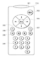
図4は本発明の第1の実施の形態に係るリモコン116の構成例を示す正面図である。本発明の第1の実施の形態に係るリモコン116は、発光部301、電源キー302、カーソルキー303、決定ボタン304、テンキー305、カラーキー306、メニューボタン307、Pボタン308を備えている。但し、本図は第1の実施の形態の説明に必要な機能を実現するための操作を行うボタンを中心に示すものであり、実際のデジタルテレビ受信装置に必要なボタンはこの限りではない。また、図4に示したものの他に、マウス等のポインティングデバイスを用いることも可能である。
【0099】
上記構成を詳述すると、発光部301は、リモコン116とデジタルテレビ受信装置100の受光部115との間で赤外線通信を行うものである。電源キー302は、デジタルテレビ受信装置100の電源をON/OFFするためのキーである。カーソルキー303は、選択カーソルを上下左右に移動させるためのキーである。決定ボタン304は、選択カーソルによって指定されている領域選択の決定を行うためのボタンである。
【0100】
メニューボタン307は、デジタルテレビ受信装置100の画像表示部112にデータ放送画面を表示するためのボタンである。カラーキー306は、例えば左から「赤」「緑」「青」「黄」と配列されたキーである。テンキー305は、デジタルテレビ受信装置100におけるチャンネルの入力や数値等の入力のためのキーである。Pボタン308については後述する。
【0101】
また、上記CPU118は、プログラム実行機能を有し、チャンネル選択、電源ON/OFF等の各操作スイッチを有する操作部114もしくはリモコン116の操作に応じて、チューナ部101、デスクランブラ102、デマルチプレクサ103、ビデオデコーダ104、オーディオデコーダ105、データストリーム処理部106、画面構成部108、表示制御部109、及び音声制御部110を制御する。
【0102】
次に、プリントコンテンツデータについての説明を行う。以下に説明を行うプリントコンテンツデータの伝送は、ISO/IEC 13818や、社団法人電波産業会(通称ARIB)における標準規格、技術資料において規定、記載されているPSI(Program Specific Information)、DSM-CC等のテーブル、記述子やそのパラメータを利用、拡張して行っているが、本発明の第1の実施の形態に係る検証、説明を行うためのみに試用したものである。
【0103】
従って、ISO/IEC 13818や、社団法人電波産業会(通称ARIB)における標準規格、技術資料において明確に規定、記載されているものではない。また、プリントコンテンツデータの伝送方法に関しては、この限りではない。デマルチプレクサ103によって取得されるプリントコンテンツデータには、テキスト情報、スクリプト情報、画像情報が含まれており、W3Cの規定するXML(eXtensible Markup Language)によって記述されている。
【0104】
デマルチプレクサ103は、TSデータに含まれる現在視聴中のチャンネルに係るPMT(Program Map Table)を取得する。取得したPMTは、上述の通り、バス120を介しCPU118に取り込まれる。CPU118は、取り込んだPMTのセクションシンタックス解析を行い、プリントコンテンツデータが現在視聴中の番組に付随して伝送されているかどうかの判別を行う(ここで、CPU118は、解析手段に相当する)。その判別は、CPU118において、上記図3で示したPMTにおける(6)のプリントコンテンツデータに関する記述があるかどうかで判別を行うこととしている。以下、上記図3の(6)についての説明を行う。
【0105】
上記図3の▲6▼で示す部分は、該当するチャンネルに係るプリントコンテンツデータについての記述を行っている。stream_type = 0x1Dは、下に示すelementary_PIDで示すPID値を有するTSパケットによって、伝送されるデータが印刷用のコンテンツデータであることを示す。elementary_PID = 0x1F41は、データカルーセル方式によって伝送されるプリントコンテンツデータや、制御情報を含むTSパケットのPIDが0x1F41であることを示す。ES_info_length = 0x003は、以下に続くコンテンツデータに関する記述子情報のバイト数が3バイトであることを示す。stream_identifier_descriptor中に記述されるcomponent_tag = 0x50は、このプリントコンテンツが現在受信中のチャンネルにおけるデフォルトコンテンツであることを示す。
【0106】
CPU118は、上述の如く記述されたPMTの解析を行い、その中にstream_type = 0x1Dが記述されていれば、現在視聴中の番組に付随するプリントコンテンツデータが存在すると識別し、表示画面上にプリントコンテンツデータの存在を通知する為の表示を行う。また、CPU118は、上述の如く記述されたPMTの解析を行い、その中にstream_type = 0x1Dが記述されていなかった場合は、表示画面上に後述のOSD表示は行わない。
【0107】
ここで、CPU118は、画面構成部108において、図5及び図6に示す如くプリントコンテンツデータの存在を示す為のOSD(On Screen Display)データを構成し、OSDデータと番組の映像データとを合成して表示制御部109に出力するように各部を制御する。
【0108】
更に、CPU118は、TSデータ中、PIDが0x1F41であるTSパケットを抽出してデータストリーム処理部106に出力するべくデマルチプレクサ103を制御する。データストリーム処理部106は、入力されたプリントコンテンツデータに復号処理を施してメモリ107に出力する。また、メモリ107は、繰り返し送信されるプリントコンテンツデータを常に更新しながら記憶する。
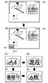
【0109】
図5に映像番組視聴中に画像表示部112に表示される画面の画面遷移の例を示す。
【0110】
図5の(A)で示すものは、現在視聴中の映像番組の表示であり、符号400で示すものは、現在113chを視聴していることを示すチャンネル番号表示である。CPU118から、バス120を介して画面構成部108にチャンネル番号表示データを送り、画面構成部108において、OSD(On Screen Display)データを構成し、表示制御部109において、ビデオデコーダ104からの番組映像データとOSDデータを合成し、画像表示部112において表示を行っている。
【0111】
図5の(B)で示すものは、現在視聴中の番組に付随するプリントコンテンツデータが存在すると識別した場合に、画像表示部112に表示される表示画面例である。符号401で示すものは、現在視聴中の113chに係るプリントコンテンツデータが存在することをユーザに通知するメッセージのOSD表示である。
【0112】
図5の(C)で示すものは、現在受信中のTSデータの中にプリントコンテンツデータが存在すると識別した場合に、画像表示部112に表示される表示画面例である。符号402で示すものは、現在視聴中の113chに係るプリントコンテンツデータが存在することをユーザに通知するマークのOSD表示である。
【0113】
図5の(D)で示すものは、現在受信中のTSデータの中にプリントコンテンツデータが存在すると識別した場合に、画像表示部112に表示される表示画面例である。符号403で示すものは、現在視聴中の113chに係るプリントコンテンツデータが存在することをユーザに通知するアイコンのOSD表示である。
【0114】
次に、データ放送番組視聴中に画像表示部112に表示される画面の画面遷移の例を図6に示す。
【0115】
図6の(A)で示すものは、現在視聴中のデータ放送の表示であり、符号500で示すものは、現在113chを視聴していることを示すチャンネル番号表示である。表示の方法は、上述と同様である。
【0116】
図6の(B)で示すものは、現在受信中のTSデータの中にプリントコンテンツデータが存在すると識別した場合に、画像表示部112に表示される表示画面例である。符号501で示すものは、現在視聴中の113chのデータ放送に係るプリントコンテンツデータが存在することをユーザに通知するメッセージのOSD表示である。
【0117】
図6の(C)で示すものは、現在受信中のTSデータの中にプリントコンテンツデータが存在すると識別した場合に、画像表示部112に表示される表示画面例である。符号502で示すものは、現在視聴中の113chに係るプリントコンテンツデータが存在することをユーザに通知するマークのOSD表示である。
【0118】
図6の(D)で示すものは、現在受信中のTSデータの中にプリントコンテンツデータが存在すると識別した場合に、画像表示部112に表示される表示画面例である。符号503で示すものは、現在視聴中の113chに係るプリントコンテンツデータが存在することをユーザに通知するアイコンのOSD表示である。
【0119】
また、ユーザは、デジタルテレビ受信装置の画像表示部112の表示画面上に、上記図5、上記図6の(B)(C)(D)に示したメッセージ401、501、マーク402、502、アイコン403、503が表示されている場合に、上記図4で示したリモコン116に装備されているPボタン308を押すことにより、プリントコンテンツデータを印刷することが可能である(ここで、Pボタン308は、受付手段に相当する)。上述の通り、プリントコンテンツデータはXMLデータ形式でメモリ107に記憶されており、その印刷用データ生成処理は、CPU118において行われる。CPU118は、メモリ107より入力したプリントコンテンツデータをXMLデータ内で指定されたレイアウト、フォント、色で印刷用データ(例えばビットマップデータ)に変換し、1394I/F122を介して、プリンタ132に出力する(ここで、1394I/F122及びCPU118は印刷制御手段に相当する)。
【0120】
以上説明したように、本発明の第1の実施の形態に係るデジタルテレビ受信装置によれば、上記図5、上記図6の(B)(C)(D)に示したメッセージ401、501、マーク402、502、アイコン403、503を、デジタルテレビ受信装置の画像表示部112を介して視聴中の番組映像、データ放送画面上にOSD表示させることで、ユーザは、現在視聴中の番組に付随するプリントコンテンツデータが存在することを容易に知ることが可能となる。
【0121】
また、上記図5、上記図6の(A)の表示状態から、現在受信中のTSデータの中に、プリントコンテンツデータが存在すると識別した場合に、CPU118において音声データを作成し、CPU118からバス120を介して音声制御部110に音声データを送り、音声出力部113から「プリントコンテンツ送信中です」等の音声メッセージを出力し、ユーザに通知することも可能である。
【0122】
また、ユーザは、音声出力部113から「プリントコンテンツ送信中です」等の音声メッセージが出力されている場合に、上記図4で示したリモコンに装備されているPボタン308を押すことにより、プリントコンテンツデータを印刷することが可能である。
【0123】
また、上述のメッセージ、マーク、アイコン表示と音声表示を組み合わせ、現在視聴中の番組に付随するプリントコンテンツデータが存在する旨をユーザに通知し、印刷を促すことも可能であり、より効果的である。
【0124】
[第2の実施の形態]
図7は本発明の第2の実施の形態に係るデジタルテレビ受信装置の全体構成を示すブロック図である。本発明の第2の実施の形態に係るデジタルテレビ受信装置は、チューナ部101、デスクランブラ102、デマルチプレクサ103、ビデオデコーダ104、オーディオデコーダ105、データストリーム処理部106、メモリ107、画面構成部108、表示制御部109、音声制御部110、画像表示部112、音声出力部113、操作部114、受光部115、ICカード制御部117、CPU118、バス120、モデム121、IEEE1394インタフェース122、蓄積部123を備えている。図中、符号116で示すものはリモコン、符号132で示すものはプリンタである。
【0125】
また、本発明の第2の実施の形態に係るリモコン116は、上記第1の実施の形態と同様に、発光部301、電源キー302、カーソルキー303、決定ボタン304、テンキー305、カラーキー306、メニューボタン307、Pボタン308を備えている(上記図4参照)。
【0126】
更に、本発明の第2の実施の形態におけるデジタルテレビ受信装置は、上記第1の実施の形態におけるデジタルテレビ受信装置の構成に加え、後述の如くプリントコンテンツを蓄積可能な蓄積部123を備えている。。図6中、上記図1と同等の機能を有するものには同一符号を付すものとする。
【0127】
尚、本発明の第2の実施の形態に係るデジタルテレビ受信装置の各部の構成、並びに映像表示出力、音声出力、EPG表示出力、データ放送表示出力に関しては、上記第1の実施の形態と同様であるので説明を省略する。
【0128】
図8は本発明の第2の実施の形態に係る検証、説明を行うために試用したTSデータに挿入したPMTのうち、上記第1の実施の形態中、図3の▲6▼で示した部分に相当する該当するチャンネルに係るプリントコンテンツデータについての記述の一例を示す説明図である。
【0129】
デマルチプレクサ103は、TSデータに含まれる現在視聴中のチャンネルに係るPMT(Program Map Table)を取得する。取得したPMTは、バス120を介しCPU118に取り込まれる。CPU118は、取り込んだPMTのセクションシンタックス解析を行い、プリントコンテンツデータがTSデータ中に存在するか(送出されているか)どうかの判別を行う。その判別は、CPU118において、図8で示したPMTにおけるプリントコンテンツデータに関する記述があるかどうかで判別を行うこととしている。
【0130】
図8におけるstream_type = 0x1Dは、下記のelementary_PIDで示すPID値を有するTSパケットによって伝送されるデータが、印刷用のコンテンツであることを示す。elementary_PID = 0x1F41は、データカルーセル方式によって伝送されるプリントコンテンツデータや、制御情報を含むTSパケットのPIDが、0x1F41であることを示す。ES_info_length = 0x00Aは、以下に続くコンテンツデータに関する記述子情報のバイト数が10バイトであることを示す。stream_identifier_descriptor中に記述されるcomponent_tag = 0x50は、このプリントコンテンツが現在受信中のチャンネルにおけるデフォルトコンテンツであることを示す。
【0131】
次に、data_component_descriptorにおいてプリントコンテンツについての付加情報を記述するprint_content_infoフィールドについて、上記図8並びに図9を参照しながら説明する。
【0132】
transmission_formatは、プリントコンテンツの伝送方式を示しており、図8中に示す値”00”は、図9に示す通り、データカルーセル方式及びイベントメッセージ伝送方式が用いられていることを示している。
【0133】
document_sizeは、プリントコンテンツが印刷される場合に最適な用紙サイズを示しており、図8中に示す値”0100”は、図9に示す通り、A4サイズの印刷用紙を用いるのが最適であることを示している。
【0134】
document_typeは、送出されているプリントコンテンツの種別(JPEG (Joint Photographic Experts Group)画像、PNG(Portable Network Graphics)画像、テキストデータ等)を示しており、図8中に示す値”0000”は、図9に示す通り、JPEG画像、PNG画像、テキストデータ等、複数種類のプリントコンテンツが含まれていることを示している。
【0135】
document_volumeは、上述のdocument_sizeで示されたサイズの用紙で送出されているプリントコンテンツを印刷した場合、合計何枚になるかを16進数値で示しており、図8中に示す値”0x06”は、合計6枚になることを示している。
【0136】
content_storable_flagは、送出されているプリントコンテンツが、例えば蓄積部123等に蓄積可能なものであるかどうかを示しており、図8中に示す値”01”は、図9に示す通り、蓄積可能であることを示している。
【0137】
CPU118は、上述の如く記述されたPMTの解析を行い、その中にstream_type = 0x1Dが記述されていれば、現在視聴中の番組に付随するプリントコンテンツデータが存在すると識別する。その場合、データ放送番組視聴中に画像表示部112に表示される画面の画面遷移の例を図10に示す。図10では、データ放送番組視聴中からの画面表示遷移を示すが、上記第1の実施の形態で示した図5、図6の関係と同様、映像番組視聴中からの画面遷移とすることも可能である。
【0138】
図10の(A)で示すものは、現在視聴中のデータ放送番組の表示である。符号900で示すものは、現在113chを視聴していることを示すチャンネル番号表示である。CPU118から、バス120を介して画面構成部108にチャンネル番号表示データを送り、画面構成部108において、OSD(On Screen Display)データを構成し、表示制御部109において、ビデオデコーダ104からの番組映像データとOSDデータを合成し、画像表示部112において表示を行っている。
【0139】
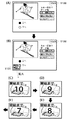
図10の(B)で示すものは、上述の如く、現在受信中のTSデータの中にプリントコンテンツデータが存在すると識別した場合に、画像表示部112に表示される表示画面例である。符号901で示すものは、現在視聴中の113chに係るプリントコンテンツデータが存在することをユーザに通知するアイコンのOSD表示である。また、符号901で示すアイコンのOSDは後述の図10(C)〜(F)に示す如く表示形態が順次変化する。
【0140】
図10の(C)で示すものは、上述の如く、現在プリントコンテンツデータが存在することをユーザに通知するアイコン表示901を拡大したものであり、プリントコンテンツデータ印刷時の最適用紙サイズがA4サイズであることを知らしめている。この表示は、上述のdocument_sizeによって決定され、例えば、document_size =”0011”の場合は、アイコン中に”A3”と表示されることになる。
【0141】
図10の(D)で示すものは、上述の如く、現在プリントコンテンツデータが存在することをユーザに通知するアイコン表示901を拡大したものであり、プリントコンテンツデータのコンテンツの種別が、JPEG画像、PNG画像、テキストデータ等、混在していることを示している。この表示は、上述のdocument_typeによって決定され、例えば、document_type=”0001”の場合は、アイコン中に”JPEG”と表示されることになる。
【0142】
図10の(E)で示すものは、上述の如く、現在プリントコンテンツデータが存在することをユーザに通知するアイコン表示901を拡大したものであり、プリントコンテンツデータのコンテンツを印刷した場合、合計6枚であることを示している。この表示は、上述のdocument_volumeによって決定され、例えば、document_volume =”0x0A”の場合は、アイコン中に”10枚”と表示されることになる。
【0143】
図10の(F)で示すものは、上述の如く、現在プリントコンテンツデータが存在することをユーザに通知するアイコン表示901を拡大したものであり、プリントコンテンツデータのコンテンツが蓄積可能であることを示している。この表示は、上述のcontent_storable_flagによって決定され、例えば、content_storable_flag=”00”の場合には、アイコン中に”蓄積不可”と表示されることになる。
【0144】
また、ユーザは、表示画面上に図10の(C)、(D)、(E)に示したアイコンが表示されている時に、リモコン116に装備されているPボタン308を押すことにより、プリントコンテンツデータを印刷することが可能である。上述の通り、プリントコンテンツデータはXMLデータ形式でメモリ107に記憶されており、その印刷用データ生成処理は、CPU118において行われる。CPU118は、メモリ107より入力したプリントコンテンツデータをXMLデータ内で指定されたレイアウト、フォント、色で印刷用データ(例えばビットマップデータ)に変換し、1394I/F122を介して、プリンタ132に出力する。
【0145】
更に、ユーザは、表示画面上に図10の(F)に示したアイコンが表示されている間に、リモコン116に装備されているPボタン308を押すことにより、プリントコンテンツデータを蓄積用メモリである蓄積部123に保存しておくことが可能である。上述の通り、プリントコンテンツデータはXMLデータ形式でメモリ107に記憶されており、その印刷用データ生成処理は、CPU118において行われる。CPU118は、メモリ107より入力したプリントコンテンツデータをXMLデータ内で指定されたレイアウト、フォント、色で印刷用データ(例えばビットマップデータ)に変換し、バス120を介して蓄積部123に出力する。尚、印刷データは、XMLで記述された状態のまま蓄積部123に保存することとしてもよい。
【0146】
以上説明したように、本発明の第2の実施の形態に係るデジタルテレビ受信装置によれば、図10の(C)、(D)、(E)、(F)に示したアイコン表示は、(B)中の901で示した部分に対し順番にOSD表示されるため、ユーザは、容易に、現在視聴中の番組に付随するプリントコンテンツデータが存在することを知ることが可能となると共に、そのコンテンツの内容が「A4サイズの用紙で6枚、JPEG画像、PNG画像、テキストデータ等、混在しており、ファイル蓄積可能である」ことを簡単に知ることが可能となる。それらの情報を知ることにより、ユーザは、プリンタ132によるプリント時に、プリンタ132の紙の種類や枚数等を正確に事前準備することができる。
【0147】
また、所望のプリントコンテンツデータを保存可能としたので、番組放送終了後に落ち着いてプリントアウト処理を行うことができ、番組視聴中に慌ててプリントアウトするか否かの判断を行う必要がなくなる。 また、本実施形態では、プリントコンテンツデータの存在を示すOSD表示にプリントアウトに最適な用紙サイズ等の情報を多重したが、プリントコンテンツデータに係る情報としてはこれに限ることなく、例えば、プリントコンテンツデータの内容情報(料理のレシピ、ニュース等)を多重したり、データの内容情報に応じてOSD表示の形態を変更してもよい。
【0148】
更に、例えば、高精彩な画像がプリントコンテンツとして送信されている場合に、その旨をユーザに通知するようにしてもよい。また、上記図10(A)の表示状態から、現在受信中のTSデータの中に、プリントコンテンツデータが存在すると識別した場合に、CPU118において音声データを作成し、CPU118からバス120を介して音声制御部110に音声データを送り、音声出力部113から「プリントコンテンツ送信中です」、「A4サイズの用紙を用意して下さい。」等の音声メッセージを出力し、ユーザに通知することも可能である。
【0149】
また、ユーザは、音声出力部113から「プリントコンテンツ送信中です」、「A4サイズの用紙を用意して下さい。」等の音声メッセージが出力されている場合に、上記図4で示したリモコンに装備されているPボタン308を押すことにより、プリントコンテンツデータを印刷することが可能である。
【0150】
また、上述のメッセージ、マーク、アイコン表示と音声表示を組み合わせ、現在視聴中の番組に付随するプリントコンテンツデータが存在する旨やプリントアウトに最適な用紙サイズ等をユーザに通知し、印刷を促すことも可能であり、より効果的である。
【0151】
[第3の実施の形態]
本発明の第3の実施の形態に係るデジタルテレビ受信装置は、上記第1の実施の形態と同様に、チューナ部101、デスクランブラ102、デマルチプレクサ103、ビデオデコーダ104、オーディオデコーダ105、データストリーム処理部106、メモリ107、画面構成部108、表示制御部109、音声制御部110、画像表示部112、音声出力部113、操作部114、受光部115、ICカード制御部117、CPU118、バス120、モデム121、IEEE1394インタフェース122を備えている(上記図1参照)。図中、符号116で示すものはリモコン、符号132で示すものはプリンタである。
【0152】
また、本発明の第3の実施の形態に係るリモコン116は、上記第1の実施の形態と同様に、発光部301、電源キー302、カーソルキー303、決定ボタン304、テンキー305、カラーキー306、メニューボタン307、Pボタン308を備えている(上記図4参照)。
【0153】
尚、本発明の第3の実施の形態に係るデジタルテレビ受信装置の各部の構成、並びに映像表示出力、音声出力、EPG表示出力、データ放送表示出力に関しては、上記第1の実施の形態と同様であるので省略する。
【0154】
図11は本発明の第3の実施の形態に係る検証、説明を行うために試用したTSデータに挿入したPMTのうち、上記第1の実施の形態中、図3の▲6▼で示した部分に相当する該当するチャンネルに係るプリントコンテンツについての記述の一例を示す説明図である。
【0155】
デマルチプレクサ103は、TSデータに含まれる現在視聴中のチャンネルに係るPMT(Program Map Table)を取得する。取得したPMTは、バス120を介しCPU118に取り込まれる。CPU118は、取り込んだPMTのセクションシンタックス解析を行い、現在視聴中の番組に付随するプリントコンテンツデータが存在するか(送出されているか)どうかの判別を行う。その判別は、CPU118において、図11で示したPMTにおけるプリントコンテンツデータに関する記述があるかどうかで判別を行うこととしている。
【0156】
図11におけるstream_type = 0x1Dは、下記のelementary_PIDで示すPID値を有するTSパケットによって伝送されるデータが、印刷用のコンテンツであることを示す。elementary_PID = 0x1F41は、データカルーセル方式によって伝送されるプリントコンテンツデータや、制御情報を含むTSパケットのPIDが、0x1F41であることを示す。ES_info_length = 0x012は、以下に続くコンテンツデータに関する記述子情報のバイト数が18バイトであることを示す。stream_identifier_descriptor中に記述されるcomponent_tag = 0x50は、このプリントコンテンツが現在受信中のチャンネルにおけるデフォルトコンテンツであることを示す。
【0157】
次に、data_component_descriptorにおいてプリントコンテンツデータの送出時間情報を記述するprint_time_infoフィールドについて説明する。
【0158】
start_timeは、プリントコンテンツデータの送出開始時刻を示しており、日本標準時(JST)と、修正ユリウス日(MJD)による現在日付と、現在時刻を含んでいる。このフィールドは、MJDの開16ビットが16ビットで符号化され、続く24ビットが6個の4ビット2進化10進数(BCD)で符号化される。図11中に示す値”0xC9BF120000”は、プリントコンテンツデータの送出開始時刻が”2000年4月13日 12時00分00秒”であることを示している。尚、この符号化方法は、電波産業会(通称ARIB)における標準規格「デジタル放送に使用する番組配列情報」に規定されているTDT(Time Description Table)又はTOT(Time Offset Table)において記述されるJST_timeと同様である。
【0159】
durationは、プリントコンテンツデータの送出時間を示しており、24ビットが6個の4ビット2進化10進数(BCD)で符号化される。図11中に示す値”0x010000”は、プリントコンテンツデータの送出時間が”1時間0分0秒”であることを示している。
【0160】
なお、ここで、プリントコンテンツデータの送出開始時刻は、繰り返し送信されるプリントコンテンツデータ中、初回のデータ送信開始時刻であって、送信時間は、繰り返し送信されるプリントコンテンツデータの初回から最後の回迄の一連のデータ送信時間である。
【0161】
CPU118は、上述の如く記述されたPMTの解析を行い、その中にstream_type = 0x1Dが記述されていれば、現在受信中のTSデータの中にプリントコンテンツデータが存在すると識別する。その場合、データ放送番組視聴中に画像表示部112に表示される画面の画面遷移の例を図12に示す。
【0162】
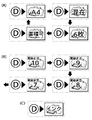
図12の(A)で示すものは、現在視聴中のデータ放送番組の表示である。符号1100で示すものは、現在113chを視聴していることを示すチャンネル番号表示である。CPU118から、バス120を介して画面構成部108にチャンネル番号表示データを送り、画面構成部108において、OSD(On Screen Display)データを構成し、表示制御部109において、ビデオデコーダ104からの番組映像データとOSDデータを合成し、画像表示部112において表示を行っている。
【0163】
図12の(B)で示すものは、上述の如く、現在受信中のTSデータの中にプリントコンテンツデータが存在すると識別した場合に、画像表示部112に表示される表示画面例である。符号1101で示すものは、現在視聴中の113chに係るプリントコンテンツデータが存在することをユーザに通知するアイコンのOSD表示である。
【0164】
図12の(C)で示すものは、上述の如く、現在プリントコンテンツデータが存在することをユーザに通知するアイコン表示1101を拡大したものであり、プリントコンテンツデータが”10秒後”から送出開始されることを示している。
【0165】
CPU118は、TDT又はTOTで示されている現在時刻情報と、図11のprint_time_infoフィールドにおけるstart_timeに記述されている情報とから、時間差を計算し、図12の(C)のアイコンに表示する数字を決定している。例えばTDT又はTOTに記述されている現在時刻が、”0xC9BF115950”(=2000年4月13日11時59分50秒)、図11に示すstart_timeが、” 0xC9BF120000”(=2000年4月13日12時00分00秒)であった場合に、時間差が10秒であるため、図12の(C)の如き表示を行う。
【0166】
その後は、CPU118が備えるタイマ手段(図示略)により時間カウントを行い、”9秒後”であれば図12の(D)、 ”8秒後”であれば図12の(E) ”7秒後”であれば図12の(F)の如く、順次更新し、プリントコンテンツデータの伝送が開始される時刻まで、即ち”0秒後”までカウント、更新表示を行う。
【0167】
上述したようなアイコン表示を行うことにより、ユーザは、プリントコンテンツデータの伝送が開始される時刻を予め認識することが可能となり、プリンタの用紙等の準備を前もって行うことが可能となる。尚、本実施形態では時間カウント開始を10秒前からとしたが、時間カウント開始時刻は任意とすることが可能であり、例えば20秒前でも1分前でもよい。
【0168】
また、上述の如く伝送が開始されたプリントコンテンツデータが、図11に示されたduration(プリントコンテンツデータの送出時間)の通りに伝送され(図11中では1時間とした)、1時間後にその伝送が終了される場合、データ放送番組視聴中に画像表示部112に表示される画面の画面遷移の例を図13に示す。
【0169】
図13の(A)で示すものは、現在視聴中のデータ放送番組の表示である。CPU118から、バス120を介して画面構成部108にチャンネル番号表示データを送り、画面構成部108において、OSD(On Screen Display)データを構成し、表示制御部109において、ビデオデコーダ104からの番組映像データとOSDデータを合成し、画像表示部112において表示を行っている。
【0170】
図13の(B)で示すものは、上述の如く、プリントコンテンツデータの伝送が終了すると識別した場合に、画像表示部112に表示される表示画面例である。符号1201で示すものは、現在視聴中の113chに係るプリントコンテンツデータの伝送がまもなく終了することをユーザに通知するアイコンのOSD表示である。
【0171】
図13の(C)で示すものは、上述の如く、プリントコンテンツデータ伝送が終了することをユーザに通知するアイコン表示1201を拡大したものであり、プリントコンテンツデータが”10秒後”に伝送終了されることを示している。
【0172】
CPU118は、図11のprint_time_infoフィールドにおけるstart_timeに記述されている情報に記述された送出開始時間から、タイマ手段(図示略)によって時間カウントを開始し、図11のprint_time_infoフィールドにおけるdurationに記述された時間情報との時間差により、図13の(C)のアイコンに表示する数字を決定している。例えば、図11に示したdurationが、”0x011100”(=1時間0分0秒)であり、タイマ手段によってカウントされた時間が59分50秒となった場合に、時間差が10秒であるため、図13の(C)の如き表示を行う。
【0173】
その後は、CPU118が備えるタイマ手段(図示略)により、時間カウントを行い、”9秒後”であれば図13の(D)、 ”8秒後”であれば図13の(E) ”7秒後”であれば図13の(F)の如く、順次更新し、プリントコンテンツデータの伝送が終了される時刻まで、即ち”0秒後”までカウント、更新表示を行う。尚、本実施形態では時間カウント開始を10秒前からとしたが、20秒前でも、1分前でもよい。
【0174】
上述したようなアイコン表示を行うことにより、ユーザは、プリントコンテンツデータの伝送が終了される時刻を予め認識することが可能となり、プリントコンテンツデータの伝送が終了してしまいプリントコンテンツデータの印刷ができなくなることを防止することが可能となる。
【0175】
以上説明したように、本発明の第3の実施の形態に係るデジタルテレビ受信装置によれば、上記アイコン表示により、ユーザは、プリントコンテンツデータの伝送が開始される時刻を予め認識することが可能となり、プリンタの用紙等の準備を前もって行うことが可能となる。
【0176】
また、上記アイコン表示により、ユーザはプリントコンテンツデータの伝送が終了される時刻を予め認識することが可能となり、プリントコンテンツデータの伝送が終了してしまいプリントコンテンツデータの印刷ができなくなることを防止することが可能となる。
【0177】
また、上記図12(A)若しくは上記図13(A)の表示状態から、現在受信中のTSデータの中に、プリントコンテンツデータが存在すると識別した場合に、CPU118において音声データを作成し、CPU118からバス120を介して音声制御部110に音声データを送り、音声出力部113から「プリントコンテンツ送信開始まで10秒です。」等の音声メッセージを出力し、ユーザに通知することも可能である。
【0178】
また、上述のメッセージ、マーク、アイコン表示と音声表示を組み合わせ、現在視聴中の番組に付随するプリントコンテンツデータの送信開始及び送信終了のタイミングをユーザに通知し、印刷を促すことも可能であり、より効果的である。
【0179】
[第4の実施の形態]
本発明の第4の実施の形態に係るデジタルテレビ受信装置は、上記第1の実施の形態と同様に、チューナ部101、デスクランブラ102、デマルチプレクサ103、ビデオデコーダ104、オーディオデコーダ105、データストリーム処理部106、メモリ107、画面構成部108、表示制御部109、音声制御部110、画像表示部112、音声出力部113、操作部114、受光部115、ICカード制御部117、CPU118、バス120、モデム121、IEEE1394インタフェース122を備えている(上記図1参照)。図中、符号116で示すものはリモコン、符号132で示すものはプリンタである。
【0180】
また、本発明の第4の実施の形態に係るリモコン116は、上記第1の実施の形態と同様に、発光部301、電源キー302、カーソルキー303、決定ボタン304、テンキー305、カラーキー306、メニューボタン307、Pボタン308を備えている(上記図4参照)。
【0181】
尚、本発明の第4の実施の形態に係るデジタルテレビ受信装置の各部の構成、並びに映像表示出力、音声出力、EPG表示出力、データ放送表示出力に関しては、上記第1の実施の形態と同様であるので説明を省略する。
【0182】
図14は本発明の第4の実施の形態に係る、上記第1の実施の形態同様、上述の如く記述されたPMTの解析を行い、現在視聴中の番組に付随するプリントコンテンツデータが存在すると識別し、接続されるプリンタ132に何らかの問題が生じている場合に、画像表示部112に表示される画面の画面遷移の例を示す説明図である。図14では、データ放送番組視聴中からの画面表示遷移を示すが、上記第1の実施の形態で示した図5、図6の関係と同様、映像番組視聴中からの画面遷移とすることも可能である。
【0183】
図14の(A)で示すものは、現在視聴中のデータ放送番組の表示である。CPU118から、バス120を介して画面構成部108にチャンネル番号表示データを送り、画面構成部108において、OSD(On Screen Display)データを構成し、表示制御部109において、ビデオデコーダ104からの番組映像データとOSDデータを合成し、画像表示部112において表示を行っている。
【0184】
図14の(B)で示すものは、上述の如く、現在受信中のTSデータの中にプリントコンテンツデータが存在すると識別し、且つプリンタ132に何らかの問題が生じている場合に、画像表示部112に表示される表示画面例である。符号1301で示すものは、接続されたプリンタ132に何らかの問題が生じている場合にOSD表示されるマークである。本実施形態における何らかの問題とは、プリンタ132が接続されていない、プリンタ132の電源が入っていない、プリンタ132のインク切れ、プリンタ132の用紙が無い、紙詰まり状態、等々を想定している。
【0185】
図14の(C)で示すものは、上述の如く、現在受信中のTSデータの中にプリントコンテンツデータが存在すると識別し、且つプリンタ132に何らかの問題が生じている場合に、画像表示部112に表示される表示画面例である。符号1303で示すものは、プリンタ132が接続されていない場合に、接続を促すためにOSD表示されるアイコンである。また、符号1304で示すものは、プリンタ132の電源が入っていない場合に、電源投入を促すためにOSD表示されるアイコンである。また、符号1305で示すものは、プリンタ132のインクが切れている場合に、インクの補充を促すためにOSD表示されるアイコンである。また、符号1306で示すものは、プリンタ132に用紙が準備されていない場合に、用紙の補充を促すためにOSD表示されるアイコンである。また、符号1307で示すものは、プリンタ132に用紙が詰まって正しく印刷できない状態にある場合に、OSD表示されるアイコンである。
【0186】
以上説明したように、本発明の第4の実施の形態に係るデジタルテレビ受信装置によれば、上述したようなアイコン表示を行うことにより、ユーザは、番組視聴中、プリントコンテンツデータが存在する場合に、プリンタ132に何らかの問題があることを容易に認識することが可能となり、プリントコンテンツデータの印刷ができなくなることを防止することが可能となる。
【0187】
また、上述したプリンタ132における問題を音声のみ或いはアイコン表示と音声を組み合わせることにより、ユーザに通知する構成としても同様の効果を得ることが可能である。
【0188】
[第5の実施の形態]
本発明の第5の実施の形態に係るデジタルテレビ受信装置は、上記第1の実施の形態と同様に、チューナ部101、デスクランブラ102、デマルチプレクサ103、ビデオデコーダ104、オーディオデコーダ105、データストリーム処理部106、メモリ107、画面構成部108、表示制御部109、音声制御部110、画像表示部112、音声出力部113、操作部114、受光部115、ICカード制御部117、CPU118、バス120、モデム121、IEEE1394インタフェース122を備えている(上記図1参照)。図中、符号116で示すものはリモコン、符号132で示すものはプリンタである。
【0189】
また、本発明の第5の実施の形態に係るリモコン116は、上記第1の実施の形態と同様に、発光部301、電源キー302、カーソルキー303、決定ボタン304、テンキー305、カラーキー306、メニューボタン307、Pボタン308を備えている(上記図4参照)。
【0190】
尚、本発明の第5の実施の形態に係るデジタルテレビ受信装置の各部の構成、並びに映像表示出力、音声出力、EPG表示出力、データ放送表示出力に関しては、上記第1の実施の形態と同様であるので説明を省略する。
【0191】
図15は本発明の第5の実施の形態に係る、映像番組視聴中において、現在視聴中の番組に付随するデータ放送及びプリントコンテンツデータが存在すると識別した場合に、画像表示部112に表示される画面の画面遷移の例を示す説明図である。
【0192】
図15の(A)で示すものは、現在視聴中の映像番組の表示である。
【0193】
図15の(B)で示すものは、現在視聴中の番組に付随するデータ放送とプリントコンテンツデータが存在すると識別した場合に、画像表示部112に表示される表示画面例である。符号1501で示すものは、映像番組視聴中にデータ放送、プリントコンテンツデータが存在することをユーザに通知するメッセージのOSD表示である。
【0194】
図15の(C)で示すものは、現在視聴中の番組に付随するデータ放送とプリントコンテンツデータが存在すると識別した場合に、画像表示部112に表示される表示画面例である。符号1502で示すものは、映像番組視聴中にデータ放送、プリントコンテンツデータが存在することをユーザに通知するマークのOSD表示である。
【0195】
図15の(D)で示すものは、現在視聴中の番組に付随するデータ放送とプリントコンテンツデータが存在すると識別した場合に、画像表示部112に表示される表示画面例である。符号1503で示すものは、映像番組視聴中にデータ放送、プリントコンテンツデータが存在することをユーザに通知するアイコンのOSD表示である。
【0196】
上記画像表示部112における1501、1502、1503の表示部分に、上記実施形態で述べた、用紙サイズ、プリントコンテンツの種別、印刷枚数、蓄積の可、不可を知らしめるアイコンを表示させることも可能である。その例を図16の(A)に示す。
【0197】
また、現在視聴中の番組に付随するデータ放送に係るプリントコンテンツデータが送出される予定であると識別した場合、上記画像表示部112における1501、1502、1503の表示部分に、上記実施形態で述べたプリントコンテンツデータ送出開始までの時間を知らしめるアイコンを表示させることも可能である。その例を図16の(B)に示す。尚、図示しないが、上記実施形態で述べたプリントコンテンツ送出終了までの時間を知らしめるアイコン表示を図16(B)と同様に表示可能であることは言うまでも無い。
【0198】
また、受信中のTSデータの中に、データ放送番組、プリントコンテンツデータが存在すると識別し、且つプリンタ132に何らかの問題が生じている場合に、上記画像表示部112における1501、1502、1503の表示部分に、上記実施形態で述べた、アイコンを表示させ、プリンタ132に生じている問題をユーザに知らしめることも可能である。インク切れの場合の表示例を図16の(C)に示す。
【0199】
以上説明したように、本発明の第5の実施の形態に係るデジタルテレビ受信装置によれば、データが伝送されているにも関わらず、印刷できない、印刷できなかったといった事態の発生を防止することができると共に、ユーザがプリンタの紙の種類や枚数等を正確に事前準備することができる。
【0200】
また、上述したデータ放送及びプリントコンテンツデータの存在やプリンタ132における問題等を音声のみ或いはアイコン表示と音声を組み合わせることにより、ユーザに通知する構成としても同様の効果を得ることが可能である。
【0201】
[他の実施の形態]
上記各実施形態においては、デジタルテレビ受信装置に接続し印刷を行う機器としてプリンタを例に挙げ説明したが、本発明は、これに限定されるものではなく、印刷を行う機器をファクシミリ装置としても同様の効果を得ることが可能である。
【0202】
また、上記各実施形態においては、デジタルテレビ受信装置に接続し印刷を行う機器としてプリンタを例に挙げ説明したが、本発明は、これに限定されるものではなく、印刷を行う機器をスキャナ機能・プリンタ機能・ファクシミリ機能を有する複合機(MFP)としても同様の効果を得ることが可能である。
【0203】
また、上記各実施形態においては、印刷を行う機器をデジタルテレビ受信装置とは別構成とし、IEEE1394インタフェースを介し接続する場合を例に挙げ説明したが、本発明は、これに限定されるものではなく、印刷を行う機器をデジタルテレビ受信装置と一体化する構成としても同様の効果を得ることが可能である。
【0204】
尚、本発明は、複数の機器から構成されるシステムに適用しても、1つの機器からなる装置に適用してもよい。上述した実施形態の機能を実現するソフトウエアのプログラムコードを記憶した記憶媒体等の媒体をシステム或いは装置に供給し、そのシステム或いは装置のコンピュータ(またはCPUやMPU)が記憶媒体等の媒体に格納されたプログラムコードを読み出し実行することによっても、達成されることは言うまでもない。
【0205】
この場合、記憶媒体等の媒体から読み出されたプログラムコード自体が上述した実施形態の機能を実現することになり、そのプログラムコードを記憶した記憶媒体等の媒体は本発明を構成することになる。プログラムコードを供給するための記憶媒体等の媒体としては、例えば、フロッピーディスク、ハードディスク、光ディスク、光磁気ディスク、CD−ROM、CD−R、磁気テープ、不揮発性のメモリカード、ROM、或いはネットワークを介したダウンロードなどを用いることができる。
【0206】
また、コンピュータが読み出したプログラムコードを実行することにより、上述した実施形態の機能が実現されるだけでなく、そのプログラムコードの指示に基づき、コンピュータ上で稼動しているOSなどが実際の処理の一部または全部を行い、その処理によって上述した実施形態の機能が実現される場合も含まれることは言うまでもない。
【0207】
更に、記憶媒体等の媒体から読み出されたプログラムコードが、コンピュータに挿入された機能拡張ボードやコンピュータに接続された機能拡張ユニットに備わるメモリに書き込まれた後、そのプログラムコードの指示に基づき、その機能拡張ボードや機能拡張ユニットに備わるCPUなどが実際の処理の一部または全部を行い、その処理によって上述した実施形態の機能が実現される場合も含まれることは言うまでもない。
【0208】
図18は本発明のデータ受信/出力方法を実行するプログラム及び関連データが記憶媒体からコンピュータ等の装置に供給される概念例を示す説明図である。本発明のデータ受信/出力方法を実行するプログラム及び関連データは、フロッピーディスクやCD−ROM等の記憶媒体181をコンピュータ等の装置182に装備された記憶媒体ドライブの挿入口183に挿入することで供給される。その後、本発明のデータ受信/出力方法を実行するプログラム及び関連データを、記憶媒体181から一旦ハードディスクにインストールしハードディスクからRAMにロードするか、或いはハードディスクにインストールせずに直接RAMにロードすることで、当該プログラム及び関連データを実行することが可能となる。
【0209】
この場合、本発明の第1〜第5の実施の形態に係るデジタルテレビ受信装置において、本発明のデータ受信/出力方法を実行するプログラムを実行させる場合は、例えば上記図18を参照して説明したようなコンピュータ等の装置を介してデジタルテレビ受信装置に当該プログラム及び関連データを供給するか、或いはデジタルテレビ受信装置に予め当該プログラム及び関連データを格納しておくことで、プログラム実行が可能となる。
【0210】
図17は本発明のデータ受信/出力方法を実行するプログラム及び関連データを記憶した記憶媒体の記憶内容の構成例を示す説明図である。記憶媒体は、例えばボリューム情報171、ディレクトリ情報172、プログラム実行ファイル173、プログラム関連データファイル174等の記憶内容で構成される。本発明のデータ受信/出力方法を実行するプログラムは、上述した制御手順に基づきプログラムコード化されたものである。
【0211】
【発明の効果】
以上説明したように、本発明によれば、、視聴者は容易に現在視聴中の番組に付随するプリントコンテンツデータが存在するか否かをを知ることが可能となり、プリントコンテンツデータが伝送されているにも関わらず、印刷できない、印刷できなかったといった事態の発生を防止することが可能となる。
【0212】
また、容易にプリントコンテンツデータに係る情報を知ることができ、視聴者はプリンタの用紙の種類や枚数等を正確に事前準備することができる。
【図面の簡単な説明】
【図1】本発明の第1、第3、第4、第5の実施の形態に係るデジタルテレビ受信装置の全体構成を示すブロック図である。
【図2】本発明の第1の実施の形態に係る検証、説明を行うために試用したTSデータに挿入したPMTの一例を示す説明図である。
【図3】本発明の第1の実施の形態に係る検証、説明を行うために試用したTSデータに挿入したPMTの一例を示す説明図である。
【図4】本発明の第1の実施の形態に係るリモコンの一例を示す説明図である。
【図5】本発明の第1の実施の形態に係るデジタルテレビ受信装置の画面遷移の第一の例を示す説明図である。
【図6】本発明の第1の実施の形態に係るデジタルテレビ受信装置の画面遷移の第二の例を示す説明図である。
【図7】本発明の第2の実施の形態に係るデジタルテレビ受信装置の全体構成を示すブロック図である。
【図8】本発明の第2の実施の形態に係る検証、説明を行うために試用したTSデータに挿入したPMTの一部を示す説明図である。
【図9】本発明の第2の実施の形態に係るprint_content_infoフィールドを示す説明図である。
【図10】本発明の第2の実施の形態に係るデジタルテレビ受信装置の画面遷移の例を示す説明図である。
【図11】本発明の第3の実施の形態に係る検証、説明を行うために試用したTSデータに挿入したPMTの一部を示す説明図である。
【図12】本発明の第3の実施の形態に係るデジタルテレビ受信装置の画面遷移の第一の例を示す説明図である。
【図13】本発明の第3の実施の形態に係るデジタルテレビ受信装置の画面遷移の第二の例を示す説明図である。
【図14】本発明の第4の実施の形態に係るデジタルテレビ受信装置の画面遷移の例を示す説明図である。
【図15】本発明の第5の実施の形態に係るデジタルテレビ受信装置の画面遷移の例を示す説明図である。
【図16】本発明の第5の実施の形態に係るアイコン表示例を示す説明図である。
【図17】本発明のデータ受信/出力方法を実行するプログラム及び関連データを記憶した記憶媒体の記憶内容の構成例を示す説明図である。
【図18】本発明のデータ受信/出力方法を実行するプログラム及び関連データが記憶媒体からコンピュータ等の装置に供給される概念例を示す説明図である。
【符号の説明】
101 チューナ部
103 デマルチプレクサ
109 表示制御部
110 音声制御部
112 画像表示部
113 音声出力部
118 CPU
123 蓄積部
132 プリンタ[0001]
BACKGROUND OF THE INVENTION
The present invention relates to a data receiving apparatus and method, and a storage medium, for example, data in a data broadcast receiving television broadcast receiver that receives, displays, and reproduces data broadcast content in which characters, images, sounds, videos, and the like are multiplexed. The present invention relates to a data receiving apparatus and method suitable for application to processing, and a storage medium.
[0002]
[Prior art]
Conventionally, data broadcasting has been operated by terrestrial television broadcasting, and full-scale broadcasting is about to start in satellite digital broadcasting. Each of these data broadcasts is broadcast by superimposing data on a broadcast radio wave from a broadcast station. On the receiving terminal side, data received by receiving broadcast radio waves is read into a personal computer (hereinafter referred to as a personal computer) or a dedicated terminal, and displayed on a general-purpose WWW (World Wide Web) browser software or dedicated browser software.
[0003]
Recently, provision of new services is expected by making it possible to receive data broadcasting services as described above not only with personal computers but also with television receivers. In other words, by installing a data broadcasting reception function and browser software on the television receiver itself, users without a personal computer can easily browse a variety of information, and information linked to television programs can be displayed in text and images. Service to be displayed can be provided.
[0004]
As an example, a new news service using data broadcasting has been proposed. This is because news videos and the like are recorded in advance in a storage device on the television receiver side, a data broadcast screen consisting of characters and images is presented to the user as a “news item”, and the news selected by the user via a remote control or the like is displayed. It is to play the video of the item. With such a service, it is possible to view news programs that were previously only available at a fixed time, or to view only the news items that the user wants to watch. Service can be provided.
[0005]
[Problems to be solved by the invention]
However, the above-described prior art has the following problems. That is, when a television receiver is provided with a data broadcast receiving function as described above, a large font is usually used to increase the visibility of characters. As a result, the text information that can be displayed at a time is naturally reduced. For example, in the above-mentioned news service, it is only possible to display three to five news contents on the screen, and many news items can be summarized and displayed. It was difficult to display with a photo.
[0006]
In addition, although it is possible to display information that could not be displayed at once by scrolling or switching pages, users are forced to perform unnecessary operations, and users who are not used to operating environments such as personal computers and video games Given that, it is not appropriate.
[0007]
Further, the useful contents of the broadcasted video program broadcast and data broadcast can be viewed after being printed on paper by a printer, thereby improving convenience for the user. In that case, it is conceivable to connect the television receiver to a video printer and capture and print the display screen of the television receiver. However, as described above, in order to improve the visibility of characters, a large font is usually used. As a result, the characters that are inevitably printed become large, and there is a problem in that the advantages of paper with generally high character visibility cannot be utilized as compared with television screens.
[0008]
Therefore, in order to solve the above problems, print data such as more detailed image data and character data related to the broadcast is superimposed on the television receiver display data in the video program broadcast and data broadcast. Broadcasting and printing using the data at the time of printing is also conceivable, but in that case, there is a possibility that the following demands may appear.
[0009]
(1) While viewing the video and data broadcast program, the user may not know when the print data is sent, so that the user can clearly recognize when the print data is sent. convenient.
[0010]
(2) What type of print data is being sent out because the user may not know what type of print data is being sent while viewing a video or data broadcast program. It is convenient if the user can clearly recognize this.
[0011]
(3) Since the user may not know how much volume is printed, it is convenient if the user can clearly recognize how much volume is printed.
[0012]
The present invention has been made in view of the above-described points, and prevents occurrence of a situation in which printing cannot be performed or printing cannot be performed even though data is transmitted, and the user can determine the type of paper of the printer and the like. An object of the present invention is to provide a data receiving apparatus and method, and a storage medium that can accurately prepare the number of sheets in advance.
[0013]
[Means for Solving the Problems]
In order to achieve the above object, a data receiving apparatus according to the present invention is a data receiving apparatus, and includes print data indicating broadcast program video data, print data related to the broadcast program, and attributes of the print data. Receiving means for receiving television broadcast data transmitted by multiplexing information, and the print additional information from the television broadcast data received by the receiving means.getAn acquisition unit, and the print additional information acquired by the acquisition unitYongDisplay control means for displaying display data to be displayed on the display unit together with the video data included in the television broadcast data received by the receiving means.The print additional information includes information indicating a size of a sheet on which the printing data is printed, information indicating the number of sheets on which the printing data is printed, information indicating a type of the printing data, and the printing Including at least one piece of time information for specifying the time at which the data is transmittedIt is characterized by that.
[0014]
The data receiving method according to the present invention is a data receiving method in which video data of a broadcast program, print data related to the broadcast program, and print additional information indicating attributes of the print data are multiplexed. A receiving step of receiving the transmitted television broadcast data, and the additional print information from the television broadcast data received in the receiving step.getAn acquisition step and the print additional information acquired in the acquisition step.YongA display control step for displaying the display data on the display unit together with the video data included in the television broadcast data received in the reception step.The print additional information includes information indicating a size of a sheet on which the print data is printed, information indicating the number of sheets on which the print data is printed, information indicating a type of the print data, Includes at least one piece of time information for specifying the time when printing data is transmittedIt is characterized by that.
[0015]
Also,A storage medium according to the present invention is a computer-readable storage medium storing a program for causing a computer to execute the operation of the data receiving method.
[0077]
DETAILED DESCRIPTION OF THE INVENTION
First, before describing embodiments of the present invention, an outline of the present invention will be described. When content data that can be printed is included in a digital broadcast wave, the present invention displays a message, a mark, and an icon on the screen of a digital television receiver that is displaying a video program or a data broadcast program. By outputting a message, the user is notified of this fact in an easy-to-understand manner. Hereinafter, embodiments of the present invention will be described in detail with reference to the drawings.
[0078]
[First Embodiment]
FIG. 1 is a block diagram showing the overall configuration of a digital television receiver according to the first embodiment of the present invention. The digital television receiver according to the first embodiment of the present invention includes a
[0079]
The above configuration will be described in detail along with the operation. In the
[0080]
When
[0081]
The
[0082]
By reading this PID, the
[0083]
The
[0084]
2 and 3 are explanatory diagrams showing an example of the PMT inserted in the TS data used for verification and explanation according to the first embodiment of the present invention.
[0085]
The part indicated by (1) in FIG. 2 is the same as that described in ISO / IEC 13818-1, and indicates the header part of the PMT section. Although details are omitted, the data length of the PMT is recognized. Information and channel number are described.
[0086]
The portion indicated by (2) in FIG. 2 is the same as that described in ISO / IEC 13818-1, and details are omitted, but information such as PID of a TS packet including a PCR (Program Clock Reference) value is described. Has been.
[0087]
The part indicated by (3) in FIG. 2 is the same as that described in the technical material “BS Digital Broadcasting Operation Regulations” in ISO / IEC 13818-1, the Radio Industry Association (commonly known as ARIB), and the corresponding channel. The video ES (Elementary Stream) constituting the program is described. Note that stream_type = 0x02 indicates a video stream defined by ISO / IEC 13818-2. The PID of the TS packet including the video ES is described in the elementary_PID portion. component_tag = 0x00 described in stream_identifier_descriptor indicates that this video ES is the default ES in the channel currently being received.
[0088]
The part indicated by (4) in FIG. 2 is the same as that described in the technical material “BS Digital Broadcasting Operation Regulations” in ISO / IEC 13818-1, the Radio Industry Association (commonly known as ARIB), and the corresponding channel. The audio ES (Elementary Stream) constituting the program is described. Note that stream_type = 0x0F indicates an audio stream defined by ISO / IEC 13818-7. The PID of the TS packet including the voice ES is described in the elementary_PID portion. component_tag = 0x10 described in stream_identifier_descriptor indicates that this audio ES is the default ES in the channel currently being received.
[0089]
The part indicated by (5) in FIG. 3 is the same as that described in ISO / IEC 13818-1, the technical data “BS Digital Broadcasting Operation Regulations” in the Radio Industry Association (commonly known as ARIB), and the corresponding channel. The data broadcast content included in the is described. Note that stream_type = 0x0D indicates a data carousel defined by ISO / IEC 13818-6. The PID of the TS packet including the data broadcast content is described in the elementary_PID portion. component_tag = 0x40 described in stream_identifier_descriptor indicates that this data broadcast content is the default content in the channel currently being received. data_component_descriptor is a standard in the Radio Industry Association (commonly known as ARIB), such as “ARIB STD-B10 Program Arrangement Information Used for BS Digital Broadcasting”, “ARIB STD-B24 Data Broadcast Coding and Transmission System for Digital Broadcasting”, etc. It is described and used to identify the data encoding scheme. The data_component_id described in this descriptor (descriptor) is used to identify the data encoding scheme, and data_component_id = 0x0007 indicates that it is an ARIB-XML based multimedia encoding scheme. The portion indicated by (6) in FIG. 3 will be described later.
[0090]
In accordance with the information described in the PMT described above, the
[0091]
First, the video data D1 will be described. The
[0092]
Next, the audio data D2 will be described. The
[0093]
Next, the data broadcast / EPG data D3 will be described. Electronic program guide (EPG) data is transmitted in a data structure defined by standards such as “program arrangement information used for digital broadcasting” by the Japan Radio Industry Association (commonly known as ARIB). As main configuration data, SDT (Service Description Table) that transmits information about organized channels such as TDT (Time Description Table) or TOT (Time Offset Table) that transmits current time information, organized channel names, broadcaster names, etc. ), EIT (Event Information Table) that transmits information about the program, such as the program name, broadcast start date and time, and description of the content. The TDT or TOT information is generally used for clock display of the
[0094]
Data broadcasting data is broadcasted by the DSM-CC data carousel method specified and described in ISO / IEC 13818-6, the technical data “BS Digital Broadcasting Operation Regulations” of the Radio Industries Association (commonly known as ARIB), etc. Repeatedly sends digital data. The data broadcast data acquired by the
[0095]
The data broadcast / EPG data D3 is decoded by the data
When a data broadcast display instruction is input from the
[0096]
The
[0097]
Further, an
[0098]
FIG. 4 is a front view showing a configuration example of the
[0099]
In detail, the
[0100]
The menu button 307 is a button for displaying a data broadcast screen on the
[0101]
Further, the
[0102]
Next, the print content data will be described. The transmission of print content data described below is based on ISO / IEC 13818, PSI (Program Specific Information), DSM-CC, which is defined and described in the standards of the Japan Radio Industry Association (commonly known as ARIB) and technical data. The table, descriptor, and parameters thereof are used and expanded, but are used only for verification and explanation according to the first embodiment of the present invention.
[0103]
Therefore, it is not clearly defined and described in ISO / IEC 13818, standards and technical data of the Japan Radio Industry Association (commonly known as ARIB). Further, the transmission method of print content data is not limited to this. The print content data acquired by the
[0104]
The
[0105]
The portion indicated by (6) in FIG. 3 describes the print content data relating to the corresponding channel. stream_type = 0x1D indicates that data transmitted by a TS packet having a PID value indicated by elementary_PID shown below is content data for printing. elementary_PID = 0x1F41 indicates that the PID of the TS packet including print content data and control information transmitted by the data carousel method is 0x1F41. ES_info_length = 0x003 indicates that the number of bytes of descriptor information relating to the following content data is 3 bytes. component_tag = 0x50 described in the stream_identifier_descriptor indicates that this print content is the default content in the currently received channel.
[0106]
The
[0107]
Here, the
[0108]
Further, the
[0109]
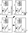
FIG. 5 shows an example of screen transition of the screen displayed on the
[0110]
5A is a display of the video program currently being viewed, and a
[0111]
FIG. 5B shows an example of a display screen displayed on the
[0112]
FIG. 5C shows an example of a display screen displayed on the
[0113]
FIG. 5D shows an example of a display screen displayed on the
[0114]
Next, FIG. 6 shows an example of the screen transition of the screen displayed on the
[0115]
6A shows the display of the data broadcast currently being viewed, and the
[0116]
FIG. 6B shows an example of a display screen displayed on the
[0117]
FIG. 6C shows an example of a display screen displayed on the
[0118]
FIG. 6D shows an example of a display screen displayed on the
[0119]
In addition, the
[0120]
As described above, according to the digital television receiver according to the first embodiment of the present invention, the
[0121]
Also, when it is identified from the display state of FIG. 5 and FIG. 6A that the print content data is present in the currently received TS data, the
[0122]
In addition, when a voice message such as “print content is being sent” is output from the
[0123]
It is also more effective to combine the above message, mark, icon display and sound display to notify the user that there is print content data associated with the program currently being viewed and to prompt the user to print. is there.
[0124]
[Second Embodiment]
FIG. 7 is a block diagram showing the overall configuration of a digital television receiver according to the second embodiment of the present invention. A digital television receiver according to the second embodiment of the present invention includes a
[0125]
Further, the
[0126]
In addition to the configuration of the digital television receiver in the first embodiment, the digital television receiver in the second embodiment of the present invention includes a
[0127]
The configuration of each part of the digital television receiver according to the second embodiment of the present invention, and the video display output, audio output, EPG display output, and data broadcast display output are the same as those in the first embodiment. Therefore, explanation is omitted.
[0128]
FIG. 8 shows the PMT inserted in the TS data used for verification and explanation according to the second embodiment of the present invention, as indicated by (6) in FIG. 3 in the first embodiment. It is explanatory drawing which shows an example of the description about the print content data which concerns on the applicable channel corresponded to a part.
[0129]
The
[0130]
In FIG. 8, stream_type = 0x1D indicates that data transmitted by a TS packet having a PID value indicated by the following elementary_PID is print content. elementary_PID = 0x1F41 indicates that the PID of the TS packet including print content data and control information transmitted by the data carousel method is 0x1F41. ES_info_length = 0x00A indicates that the number of bytes of descriptor information relating to the following content data is 10 bytes. component_tag = 0x50 described in the stream_identifier_descriptor indicates that this print content is the default content in the currently received channel.
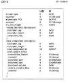
[0131]
Next, a print_content_info field that describes additional information about print content in data_component_descriptor will be described with reference to FIGS.
[0132]
The transmission_format indicates the print content transmission method, and the value “00” shown in FIG. 8 indicates that the data carousel method and the event message transmission method are used as shown in FIG.
[0133]
The document_size indicates the optimum paper size when the print content is printed, and the value “0100” shown in FIG. 8 is optimum to use A4 size printing paper as shown in FIG. Is shown.
[0134]
Document_type indicates the type of print content being sent (JPEG (Joint Photographic Experts Group) image, PNG (Portable Network Graphics) image, text data, etc.), and the value “0000” shown in FIG. As shown in FIG. 9, it shows that a plurality of types of print contents such as JPEG images, PNG images, text data, and the like are included.
[0135]
The document_volume indicates the total number of print contents when printing the print content transmitted with the size of the document_size described above, and the value “0x06” shown in FIG. , The total is 6 sheets.
[0136]
content_storable_flag indicates whether or not the sent print content can be stored in, for example, the
[0137]
The
[0138]
What is shown by (A) in FIG. 10 is a display of the data broadcast program currently being viewed. What is indicated by
[0139]
FIG. 10B shows an example of a display screen displayed on the
[0140]
As shown in FIG. 10C, the
[0141]
10D is an enlarged view of the
[0142]
FIG. 10E shows an
[0143]
10 (F) is an enlarged view of the
[0144]
In addition, when the icons shown in FIGS. 10C, 10D, and 10E are displayed on the display screen, the user presses the
[0145]
Furthermore, while the icon shown in FIG. 10F is displayed on the display screen, the user presses the
[0146]
As described above, according to the digital television receiver according to the second embodiment of the present invention, the icon displays shown in (C), (D), (E), and (F) of FIG. Since the OSD display is sequentially performed for the portion indicated by 901 in (B), the user can easily know that there is print content data associated with the program currently being viewed, It is possible to easily know that the content is “6 sheets of A4-size paper, JPEG images, PNG images, text data, etc. are mixed and files can be stored”. By knowing such information, the user can accurately prepare in advance the paper type and number of sheets of the
[0147]
Further, since desired print content data can be stored, it is possible to perform printout processing calmly after the end of program broadcast, and it is not necessary to determine whether or not to print out while viewing the program. Further, in the present embodiment, information such as the optimum paper size for printout is multiplexed on the OSD display indicating the presence of print content data. However, the information related to print content data is not limited to this, for example, print content. Data content information (cooking recipes, news, etc.) may be multiplexed, or the OSD display form may be changed according to the data content information.
[0148]
Furthermore, for example, when a high-definition image is transmitted as print content, the user may be notified of this. When it is identified from the display state of FIG. 10A that print content data is present in the currently received TS data, the
[0149]
In addition, when a voice message such as “Sending print content” or “Please prepare A4 size paper” is output from the
[0150]
In addition, the above message, mark, icon display, and audio display are combined to notify the user that there is print content data associated with the currently viewed program and the optimum paper size for printout, etc. Is also possible and more effective.
[0151]
[Third Embodiment]
As in the first embodiment, the digital television receiver according to the third embodiment of the present invention includes a
[0152]
In addition, the
[0153]
The configuration of each part of the digital television receiver according to the third embodiment of the present invention, the video display output, the audio output, the EPG display output, and the data broadcast display output are the same as in the first embodiment. Therefore, it is omitted.
[0154]
FIG. 11 shows the PMT inserted in the TS data used for verification and explanation according to the third embodiment of the present invention, as indicated by (6) in FIG. 3 in the first embodiment. It is explanatory drawing which shows an example of the description about the print content which concerns on the applicable channel corresponded to a part.
[0155]
The
[0156]
In FIG. 11, stream_type = 0x1D indicates that data transmitted by a TS packet having a PID value indicated by the following elementary_PID is a content for printing. elementary_PID = 0x1F41 indicates that the PID of the TS packet including print content data and control information transmitted by the data carousel method is 0x1F41. ES_info_length = 0x012 indicates that the number of bytes of descriptor information relating to the following content data is 18 bytes. component_tag = 0x50 described in the stream_identifier_descriptor indicates that this print content is the default content in the currently received channel.
[0157]
Next, a print_time_info field that describes print content data transmission time information in data_component_descriptor will be described.
[0158]
start_time indicates the print content data transmission start time, and includes the Japan Standard Time (JST), the current date based on the modified Julian Date (MJD), and the current time. This field is encoded with 16 bits of the MJD's open 16 bits, followed by 24 bits with 6 4-bit binary coded decimal (BCD). The value “0xC9BF120,000” shown in FIG. 11 indicates that the print content data transmission start time is “April 13, 2000, 12:00:00”. This encoding method is described in the TDT (Time Description Table) or TOT (Time Offset Table) defined in the standard "program arrangement information used for digital broadcasting" in the Radio Industries Association (commonly known as ARIB). Similar to JST_time.
[0159]
The duration indicates the transmission time of the print content data, and 24 bits are encoded by 6 4-bit binary coded decimal numbers (BCD). The value “0x010000” shown in FIG. 11 indicates that the print content data transmission time is “1
[0160]
Here, the transmission start time of the print content data is the first data transmission start time in the repeatedly transmitted print content data, and the transmission time is the first to last time of the repeatedly transmitted print content data. It is a series of data transmission time until.
[0161]
The
[0162]
What is shown by (A) in FIG. 12 is a display of the data broadcast program currently being viewed. What is denoted by
[0163]
FIG. 12B shows an example of a display screen displayed on the
[0164]
FIG. 12C is an enlarged view of the
[0165]
The
[0166]
After that, the time is counted by a timer means (not shown) provided in the
[0167]
By performing the icon display as described above, the user can recognize in advance the time at which transmission of print content data is started, and can prepare paper for the printer in advance. In the present embodiment, the time count is started from 10 seconds before, but the time count start time can be arbitrarily set, for example, 20 seconds or 1 minute before.
[0168]
In addition, the print content data whose transmission has been started as described above is transmitted according to the duration (print content data transmission time) shown in FIG. 11 (1 hour in FIG. 11). FIG. 13 shows an example of the screen transition of the screen displayed on the
[0169]
What is shown by (A) in FIG. 13 is a display of the data broadcast program currently being viewed. Channel number display data is sent from the
[0170]
FIG. 13B shows an example of a display screen displayed on the
[0171]
FIG. 13C shows an enlargement of the
[0172]
The
[0173]
Thereafter, the time is counted by a timer means (not shown) provided in the
[0174]
By performing the icon display as described above, the user can recognize in advance the time at which the transmission of the print content data is completed, and the transmission of the print content data is completed, so that the print content data can be printed. It is possible to prevent disappearance.
[0175]
As described above, according to the digital television receiver according to the third embodiment of the present invention, the icon display allows the user to recognize in advance the time when transmission of print content data starts. Thus, it is possible to prepare the printer paper and the like in advance.
[0176]
In addition, the icon display allows the user to recognize in advance the time at which the transmission of the print content data is completed, and prevents the print content data from being printed due to the completion of the transmission of the print content data. It becomes possible.
[0177]
When it is identified from the display state of FIG. 12A or FIG. 13A that print content data exists in the currently received TS data, the
[0178]
It is also possible to combine the above message, mark, icon display and sound display to notify the user of the start and end timings of transmission of print content data accompanying the currently viewed program, and prompt printing. More effective.
[0179]
[Fourth Embodiment]
As in the first embodiment, a digital television receiver according to the fourth embodiment of the present invention includes a
[0180]
The
[0181]
The configuration of each part of the digital television receiver according to the fourth embodiment of the present invention, and the video display output, audio output, EPG display output, and data broadcast display output are the same as in the first embodiment. Therefore, explanation is omitted.
[0182]
FIG. 14 shows that the PMT described as described above is analyzed as in the first embodiment, according to the fourth embodiment of the present invention, and there is print content data associated with the program currently being viewed. FIG. 11 is an explanatory diagram illustrating an example of screen transition of a screen displayed on the image display unit when there is some problem with the
[0183]
What is shown by (A) in FIG. 14 is a display of the data broadcast program currently being viewed. Channel number display data is sent from the
[0184]
FIG. 14B shows the
[0185]
FIG. 14C shows the
[0186]
As described above, according to the digital television receiver according to the fourth embodiment of the present invention, when the icon is displayed as described above, the user can view the print content data while viewing the program. In addition, it is possible to easily recognize that there is some problem in the
[0187]
In addition, the same effect can be obtained even in a configuration in which the above-described problem in the
[0188]
[Fifth Embodiment]
As in the first embodiment, a digital television receiver according to the fifth embodiment of the present invention includes a
[0189]
In addition, the
[0190]
The configuration of each part of the digital television receiver according to the fifth embodiment of the present invention, and the video display output, audio output, EPG display output, and data broadcast display output are the same as those in the first embodiment. Therefore, explanation is omitted.
[0191]
FIG. 15 is displayed on the
[0192]
What is shown in FIG. 15A is a display of the video program currently being viewed.
[0193]
FIG. 15B shows an example of a display screen displayed on the
[0194]
FIG. 15C shows an example of a display screen displayed on the
[0195]
FIG. 15D shows an example of a display screen displayed on the
[0196]
In the
[0197]
Further, when it is identified that the print content data related to the data broadcast accompanying the program currently being viewed is scheduled to be transmitted, the
[0198]
Further, when it is identified that there is a data broadcast program or print content data in the received TS data, and there is some problem with the
[0199]
As described above, according to the digital television receiver of the fifth embodiment of the present invention, it is possible to prevent the occurrence of a situation where printing cannot be performed or printing cannot be performed even though data is transmitted. In addition, the user can accurately prepare in advance the paper type and number of sheets of the printer.
[0200]
Further, the same effect can be obtained in a configuration in which the user is notified of the presence of the above-described data broadcasting and print content data, problems in the
[0201]
[Other embodiments]
In each of the above embodiments, a printer has been described as an example of a device that is connected to a digital television receiver and performs printing. However, the present invention is not limited to this, and the device that performs printing may be a facsimile device. Similar effects can be obtained.
[0202]
In each of the above embodiments, a printer has been described as an example of a device that connects to a digital television receiver and performs printing. However, the present invention is not limited to this, and the device that performs printing functions as a scanner. A similar effect can be obtained even with a multifunction peripheral (MFP) having a printer function and a facsimile function.
[0203]
In each of the above embodiments, the case where the device for printing is configured separately from the digital television receiver and connected via the IEEE1394 interface has been described as an example. However, the present invention is not limited to this. Alternatively, the same effect can be obtained even when the device for printing is integrated with the digital television receiver.
[0204]
The present invention may be applied to a system composed of a plurality of devices or an apparatus composed of a single device. A medium such as a storage medium storing software program codes for realizing the functions of the above-described embodiments is supplied to the system or apparatus, and the computer (or CPU or MPU) of the system or apparatus stores the medium in the storage medium or the like. Needless to say, this can also be achieved by reading and executing the program code.
[0205]
In this case, the program code itself read from the medium such as a storage medium realizes the functions of the above-described embodiments, and the medium such as the storage medium storing the program code constitutes the present invention. . Examples of the medium such as a storage medium for supplying the program code include a floppy disk, a hard disk, an optical disk, a magneto-optical disk, a CD-ROM, a CD-R, a magnetic tape, a nonvolatile memory card, a ROM, and a network. Downloads can be used.
[0206]
Further, by executing the program code read out by the computer, not only the functions of the above-described embodiments are realized, but also the OS running on the computer based on the instruction of the program code performs the actual processing. Needless to say, a case where the function of the above-described embodiment is realized by performing part or all of the processing is included.
[0207]
Furthermore, after the program code read from a medium such as a storage medium is written in a memory provided in a function expansion board inserted in the computer or a function expansion unit connected to the computer, based on the instruction of the program code, It goes without saying that the CPU of the function expansion board or function expansion unit performs part or all of the actual processing and the functions of the above-described embodiments are realized by the processing.
[0208]
FIG. 18 is an explanatory diagram showing a conceptual example in which a program for executing the data reception / output method of the present invention and related data are supplied from a storage medium to an apparatus such as a computer. A program for executing the data reception / output method of the present invention and related data are obtained by inserting a
[0209]
In this case, in the digital television receiving apparatus according to the first to fifth embodiments of the present invention, when the program for executing the data reception / output method of the present invention is executed, for example, referring to FIG. The program and related data can be supplied to the digital television receiver via a device such as a computer, or the program and related data can be stored in advance in the digital television receiver. Become.
[0210]
FIG. 17 is an explanatory diagram showing a configuration example of the storage contents of a storage medium storing a program for executing the data reception / output method of the present invention and related data. The storage medium includes storage contents such as
[0211]
【The invention's effect】
As described above, according to the present invention, the viewer can easily know whether or not there is print content data accompanying the currently viewed program, and the print content data is transmitted. In spite of this, it is possible to prevent the occurrence of a situation where printing cannot be performed or printing cannot be performed.
[0212]
In addition, information related to the print content data can be easily known, and the viewer can accurately prepare in advance the type and number of sheets of the printer.
[Brief description of the drawings]
FIG. 1 is a block diagram showing an overall configuration of a digital television receiver according to first, third, fourth, and fifth embodiments of the present invention.
FIG. 2 is an explanatory diagram showing an example of a PMT inserted in TS data used for verification and explanation according to the first embodiment of the present invention.
FIG. 3 is an explanatory diagram showing an example of a PMT inserted in TS data used for verification and explanation according to the first embodiment of the present invention.
FIG. 4 is an explanatory diagram showing an example of a remote control according to the first embodiment of the present invention.
FIG. 5 is an explanatory diagram illustrating a first example of screen transition of the digital television receiving device according to the first embodiment of the invention.
FIG. 6 is an explanatory diagram illustrating a second example of screen transition of the digital television receiving device according to the first embodiment of the invention.
FIG. 7 is a block diagram showing an overall configuration of a digital television receiver according to a second embodiment of the present invention.
FIG. 8 is an explanatory diagram showing a part of a PMT inserted in TS data used for verification and explanation according to the second embodiment of the present invention.
FIG. 9 is an explanatory diagram showing a print_content_info field according to the second embodiment of the present invention.
FIG. 10 is an explanatory diagram showing an example of screen transition of the digital television receiving device according to the second embodiment of the present invention.
FIG. 11 is an explanatory diagram showing a part of a PMT inserted in TS data used for verification and explanation according to a third embodiment of the present invention.
FIG. 12 is an explanatory diagram illustrating a first example of screen transition of the digital television receiving device according to the third embodiment of the present invention.
FIG. 13 is an explanatory diagram illustrating a second example of screen transition of the digital television receiving device according to the third embodiment of the present invention.
FIG. 14 is an explanatory diagram showing an example of screen transition of the digital television receiving device according to the fourth embodiment of the present invention.
FIG. 15 is an explanatory diagram showing an example of screen transition of the digital television receiving device according to the fifth embodiment of the present invention;
FIG. 16 is an explanatory diagram showing an icon display example according to the fifth embodiment of the present invention.
FIG. 17 is an explanatory diagram showing a configuration example of storage contents of a storage medium storing a program for executing a data reception / output method of the present invention and related data;
FIG. 18 is an explanatory diagram showing a conceptual example in which a program for executing a data reception / output method of the present invention and related data are supplied from a storage medium to an apparatus such as a computer.
[Explanation of symbols]
101 Tuner
103 Demultiplexer
109 Display control unit
110 Voice control unit
112 Image display
113 Audio output unit
118 CPU
123 Accumulator
132 Printer
Claims (11)
放送番組の映像データ、前記放送番組に関連する印刷用データ、及び前記印刷用データの属性を示す印刷付加情報が多重化して送信されたテレビジョン放送データを受信する受信手段と、
前記受信手段により受信されたテレビジョン放送データから前記印刷付加情報を取得する取得手段と、
前記取得手段で取得された前記印刷付加情報の内容を示す表示データを、前記受信手段により受信された前記テレビジョン放送データに含まれる前記映像データとともに表示部に表示させる表示制御手段とを備え、
前記印刷付加情報は、前記印刷用データを印刷する用紙のサイズを示す情報と、前記印刷用データを印刷する用紙の枚数を示す情報と、前記印刷用データの種別を示す情報と、前記印刷用データが送信される時間を特定するための時間情報のうちの少なくとも一つの情報を含むことを特徴とするデータ受信装置。A data receiving device,
Receiving means for receiving television broadcast data transmitted by multiplexing video data of a broadcast program, print data related to the broadcast program, and print additional information indicating attributes of the print data;
Obtaining means for obtaining the print additional information from the television broadcast data received by the receiving means;
The display data representing the contents of the print the additional information acquired by the acquisition unit, and a display control means for displaying on the display unit together with the video data contained in said received television broadcast data is by the receiving means ,
The print additional information includes information indicating a size of a sheet on which the print data is printed, information indicating the number of sheets on which the print data is printed, information indicating a type of the print data, and the print A data receiving apparatus comprising at least one piece of time information for specifying a time at which data is transmitted .
前記受付手段がユーザからの印刷指示を受けたことに応じて、前記受信手段により受信された前記印刷用データを印刷装置へ出力する印刷制御手段とを備え、
前記受付手段は、前記受信手段が前記印刷用データを受信している期間は、ユーザからの印刷指示を受け付け、前記受信手段が前記印刷用データを受信していない期間は、ユーザからの印刷指示を受け付けないことを特徴とする請求項1に記載のデータ受信装置。A receiving unit that receives a print instruction from the user;
A printing control unit that outputs the printing data received by the receiving unit to a printing device in response to the receiving unit receiving a printing instruction from a user;
The accepting unit accepts a print instruction from a user during a period when the receiving unit receives the print data, and receives a print instruction from a user during a period when the receiving unit does not receive the print data. The data receiving device according to claim 1, wherein the data receiving device is not accepted.
前記受付手段がユーザからの蓄積指示を受けたことに応じて、前記印刷用データを蓄積部に蓄積する蓄積制御手段とを備え、
前記受付手段は、前記受信手段が前記印刷用データを受信している期間は、ユーザからの蓄積指示を受け付け、前記受信手段が前記印刷用データを受信していない期間は、ユーザからの蓄積指示を受け付けないことを特徴とする請求項1に記載のデータ受信装置。A receiving unit for receiving a storage instruction from the user;
A storage control unit that stores the print data in a storage unit in response to the reception unit receiving a storage instruction from a user;
The accepting means accepts an accumulation instruction from a user during a period when the receiving means is receiving the printing data, and an accumulation instruction from a user when the receiving means is not receiving the printing data. The data receiving device according to claim 1, wherein the data receiving device is not accepted.
ユーザからの印刷指示を受け付ける受付手段と、
前記受付手段がユーザからの印刷指示を受けたことに応じて、前記蓄積手段に蓄積された前記印刷用データを印刷装置へ出力する印刷制御手段とを備えることを特徴とする請求項1に記載のデータ受信装置。And storage means for storing the printing data received by the receiving means;
A receiving means for receiving a print instruction from the user;
The printing control unit according to claim 1, further comprising: a print control unit that outputs the printing data stored in the storage unit to a printing apparatus in response to the reception unit receiving a print instruction from a user. Data receiver.
放送番組の映像データ、前記放送番組に関連する印刷用データ、及び前記印刷用データの属性を示す印刷付加情報が多重化して送信されたテレビジョン放送データを受信する受信ステップと、
前記受信ステップで受信されたテレビジョン放送データから前記印刷付加情報を取得する取得ステップと、
前記取得ステップで取得された前記印刷付加情報の内容を示す表示データを、前記受信ステップで受信された前記テレビジョン放送データに含まれる前記映像データとともに表示部に表示させる表示制御ステップとを有し、
前記印刷付加情報は、前記印刷用データを印刷する用紙のサイズを示す情報と、前記印刷用データを印刷する用紙の枚数を示す情報と、前記印刷用データの種別を示す情報と、前記印刷用データが送信される時間を特定するための時間情報のうちの少なくとも一つの情報を含むことを特徴とするデータ受信方法。A data receiving method,
A receiving step of receiving television broadcast data transmitted by multiplexing video data of a broadcast program, print data related to the broadcast program, and print additional information indicating attributes of the print data;
An acquisition step of acquiring the print additional information from the television broadcast data received in the reception step;
Yes and a display control step of displaying on the display unit display data indicating the contents of the print the additional information obtained by the obtaining step, together with the video data included the television broadcast data received by the receiving step And
The print additional information includes information indicating a size of a sheet on which the print data is printed, information indicating the number of sheets on which the print data is printed, information indicating a type of the print data, and the print A data receiving method comprising: at least one piece of time information for specifying a time at which data is transmitted .
前記受付ステップでユーザからの印刷指示を受けたことに応じて、前記受信ステップで受信された前記印刷用データを印刷装置へ出力する印刷制御ステップとを有し、
前記受信ステップで前記印刷用データを受信している期間は、前記受付ステップでユーザからの印刷指示を受け付け、前記受信ステップで前記印刷用データを受信していない期間は、前記受付ステップでユーザからの印刷指示を受け付けないことを特徴とする請求項6に記載のデータ受信方法。A reception step for receiving a print instruction from the user;
A printing control step of outputting the printing data received in the receiving step to a printing device in response to receiving a printing instruction from the user in the receiving step;
During the period in which the printing data is received in the receiving step, a printing instruction is received from the user in the receiving step, and during the period in which the printing data is not received in the receiving step, The data receiving method according to claim 6, wherein the print instruction is not accepted.
前記受付ステップでユーザからの蓄積指示を受けたことに応じて、前記印刷用データを蓄積手段に蓄積する蓄積制御ステップとを有し、
前記受信ステップで前記印刷用データを受信している期間は、前記受付ステップでユーザからの蓄積指示を受け付け、前記受信ステップで前記印刷用データを受信していない期間は、前記受付ステップでユーザからの蓄積指示を受け付けないことを特徴とする請求項6に記載のデータ受信方法。And a reception step for accepting an accumulation instruction from the user;
A storage control step of storing the print data in a storage means in response to receiving a storage instruction from the user in the reception step;
During the period in which the printing data is received in the receiving step, an accumulation instruction is received from the user in the receiving step, and during the period in which the printing data is not received in the receiving step, The data receiving method according to claim 6, wherein the storage instruction is not accepted.
ユーザからの印刷指示を受け付ける受付ステップと、
前記受付ステップでユーザからの印刷指示を受けたことに応じて、前記蓄積手段に蓄積された前記印刷用データを印刷装置へ出力する印刷制御ステップとを有することを特徴とする請求項6に記載のデータ受信方法。A storage step for storing the print data received in the reception step;
A reception step for receiving a print instruction from the user;
Wherein in response to receiving a print instruction from a user at the reception step, according to claim 6, characterized in that it comprises a print control step of outputting the printing data stored in said storage means to the printing apparatus Data receiving method.
Priority Applications (4)
| Application Number | Priority Date | Filing Date | Title |
|---|---|---|---|
| JP2000351992A JP4164227B2 (en) | 2000-11-17 | 2000-11-17 | Data receiving apparatus and method, and storage medium |
| US09/986,253 US7385719B2 (en) | 2000-11-17 | 2001-11-08 | Data receiving apparatus, method and storage medium therefor |
| EP01309492A EP1209909B1 (en) | 2000-11-17 | 2001-11-09 | Data receiving apparatus method and storage medium therefor |
| DE60135198T DE60135198D1 (en) | 2000-11-17 | 2001-11-09 | Data receiving device and method and corresponding information carrier |
Applications Claiming Priority (1)
| Application Number | Priority Date | Filing Date | Title |
|---|---|---|---|
| JP2000351992A JP4164227B2 (en) | 2000-11-17 | 2000-11-17 | Data receiving apparatus and method, and storage medium |
Publications (3)
| Publication Number | Publication Date |
|---|---|
| JP2002158976A JP2002158976A (en) | 2002-05-31 |
| JP2002158976A5 JP2002158976A5 (en) | 2007-03-22 |
| JP4164227B2 true JP4164227B2 (en) | 2008-10-15 |
Family
ID=18824953
Family Applications (1)
| Application Number | Title | Priority Date | Filing Date |
|---|---|---|---|
| JP2000351992A Expired - Fee Related JP4164227B2 (en) | 2000-11-17 | 2000-11-17 | Data receiving apparatus and method, and storage medium |
Country Status (4)
| Country | Link |
|---|---|
| US (1) | US7385719B2 (en) |
| EP (1) | EP1209909B1 (en) |
| JP (1) | JP4164227B2 (en) |
| DE (1) | DE60135198D1 (en) |
Families Citing this family (19)
| Publication number | Priority date | Publication date | Assignee | Title |
|---|---|---|---|---|
| CN1529980A (en) * | 2001-07-16 | 2004-09-15 | ���µ�����ҵ��ʽ���� | Data broadcast printing method system and programe |
| KR100421360B1 (en) * | 2001-11-03 | 2004-03-06 | 엘지전자 주식회사 | Method and apparatus for displaying an additional function of digital broadcasting program |
| JP3935412B2 (en) * | 2002-09-09 | 2007-06-20 | キヤノン株式会社 | Receiving apparatus, receiving apparatus control method, and stream data distribution system |
| JP4310994B2 (en) * | 2002-10-28 | 2009-08-12 | 富士ゼロックス株式会社 | Image processing device |
| JP4125106B2 (en) * | 2002-12-11 | 2008-07-30 | キヤノン株式会社 | Data broadcast receiving and reproducing apparatus and data broadcast receiving and reproducing method |
| TW570449U (en) * | 2003-05-30 | 2004-01-01 | Aviquest Technology Co Ltd | Multi-media playing TV |
| JP2005100415A (en) * | 2003-09-25 | 2005-04-14 | Ricoh Co Ltd | Multimedia print driver dialogue interface |
| JP4402423B2 (en) | 2003-10-22 | 2010-01-20 | キヤノン株式会社 | Data reception processing device |
| JP4617167B2 (en) * | 2004-02-04 | 2011-01-19 | キヤノン株式会社 | Broadcast receiving apparatus and control method thereof |
| JP4225235B2 (en) | 2004-04-20 | 2009-02-18 | セイコーエプソン株式会社 | Image display apparatus and error processing method for image display apparatus |
| JP4717499B2 (en) * | 2004-06-08 | 2011-07-06 | キヤノン株式会社 | Broadcast receiving apparatus and control method thereof |
| JP5004319B2 (en) * | 2005-09-05 | 2012-08-22 | キヤノン株式会社 | Display device and program |
| JP4876529B2 (en) * | 2005-10-25 | 2012-02-15 | ブラザー工業株式会社 | Image forming apparatus |
| JP2007210162A (en) | 2006-02-08 | 2007-08-23 | Fujifilm Corp | Printer for digital broadcasting |
| JP2007251549A (en) | 2006-03-15 | 2007-09-27 | Fujifilm Corp | Network printing equipment |
| JP5137520B2 (en) * | 2007-10-02 | 2013-02-06 | キヤノン株式会社 | Digital broadcast receiving apparatus and control method of digital broadcast receiving apparatus |
| JP5531942B2 (en) * | 2010-12-20 | 2014-06-25 | コニカミノルタ株式会社 | Image forming apparatus |
| CN103182864B (en) * | 2011-12-31 | 2015-05-20 | 北大方正集团有限公司 | Digital printing synchronous control device and control method |
| US20150046943A1 (en) * | 2013-08-12 | 2015-02-12 | Sony Corporation | Automatic switching from primary to secondary audio during emergency broadcast |
Family Cites Families (26)
| Publication number | Priority date | Publication date | Assignee | Title |
|---|---|---|---|---|
| US45966A (en) * | 1865-01-24 | Improvement in horse-power elevators and excavators | ||
| US179046A (en) * | 1876-06-20 | Improvement in methods and apparatus for laying out coat-patterns | ||
| JPS59226576A (en) * | 1983-06-08 | 1984-12-19 | Mitsubishi Electric Corp | Printer of television receiver |
| KR870001840B1 (en) * | 1983-06-08 | 1987-10-15 | 미쓰비시덴기 가부시기가이샤 | Printer device of television receiver |
| JP3339722B2 (en) * | 1992-07-28 | 2002-10-28 | 富士写真フイルム株式会社 | Video printer |
| US5594426A (en) * | 1993-09-20 | 1997-01-14 | Hitachi, Ltd. | Network station and network management system |
| US5488423A (en) * | 1994-11-17 | 1996-01-30 | U.S. Narrow Networks, Inc. | Home communication method and apparatus |
| US5886732A (en) * | 1995-11-22 | 1999-03-23 | Samsung Information Systems America | Set-top electronics and network interface unit arrangement |
| JP2966785B2 (en) * | 1995-12-21 | 1999-10-25 | 全国朝日放送株式会社 | Multiplex broadcasting receiver |
| JPH10226139A (en) | 1997-02-14 | 1998-08-25 | Canon Inc | Image forming system, image forming apparatus, and medium |
| JPH10229534A (en) | 1997-02-14 | 1998-08-25 | Canon Inc | Image pickup device, video print system and their control method |
| JPH11112914A (en) | 1997-09-29 | 1999-04-23 | Seiko Epson Corp | Information print system and storage medium stored with information print processing program in the information print system |
| JP3201319B2 (en) * | 1997-11-01 | 2001-08-20 | 日本電気株式会社 | Electronic devices that can be connected to a network |
| US6175861B1 (en) * | 1998-02-06 | 2001-01-16 | Henry R. Williams, Jr. | Apparatus and method for providing computer display data from a computer system to a remote display device |
| JP3684818B2 (en) | 1998-02-23 | 2005-08-17 | セイコーエプソン株式会社 | Television broadcast multiplexed data printing method and system, and recording medium recording a television broadcast multiplexed data processing program |
| US6366359B1 (en) * | 1998-04-09 | 2002-04-02 | Canon Kabushiki Kaisha | Integrated digital television and video printer |
| JPH11341423A (en) | 1998-05-25 | 1999-12-10 | Canon Inc | Information processing unit |
| JP3159174B2 (en) * | 1998-06-19 | 2001-04-23 | 日本電気株式会社 | Printer control device |
| JP2000092416A (en) | 1998-09-08 | 2000-03-31 | Olympus Optical Co Ltd | Image printing device |
| US6005482A (en) * | 1998-09-17 | 1999-12-21 | Xerox Corporation | Surface mounted information collage |
| FR2784936B1 (en) * | 1998-10-23 | 2001-04-13 | Canon Kk | METHOD AND DEVICE FOR MANAGING THE RESOURCES OF A PRINTING PRODUCT AVAILABLE IN A PRINTER |
| US6273635B1 (en) * | 1999-05-10 | 2001-08-14 | Swanson Systems, Inc. | Mounting fixture for a modular assembly machine |
| US6690481B1 (en) * | 1999-07-20 | 2004-02-10 | Canon Kabushiki Kaisha | Internet-based push printing over cable network |
| US6652174B1 (en) * | 1999-07-27 | 2003-11-25 | Hewlett-Packard Development Company, L.P. | Hybrid set-top box and printing device |
| JP2001080141A (en) * | 1999-09-14 | 2001-03-27 | Sony Corp | Printing control device and method, printing apparatus and printing method, printing system and printing method |
| JP4265053B2 (en) * | 1999-11-04 | 2009-05-20 | ソニー株式会社 | Digital broadcast receiving system, digital broadcast receiving apparatus, receiving apparatus, printing apparatus, and printing method |
-
2000
- 2000-11-17 JP JP2000351992A patent/JP4164227B2/en not_active Expired - Fee Related
-
2001
- 2001-11-08 US US09/986,253 patent/US7385719B2/en not_active Expired - Fee Related
- 2001-11-09 EP EP01309492A patent/EP1209909B1/en not_active Expired - Lifetime
- 2001-11-09 DE DE60135198T patent/DE60135198D1/en not_active Expired - Lifetime
Also Published As
| Publication number | Publication date |
|---|---|
| EP1209909A3 (en) | 2004-12-01 |
| EP1209909B1 (en) | 2008-08-06 |
| JP2002158976A (en) | 2002-05-31 |
| US7385719B2 (en) | 2008-06-10 |
| EP1209909A2 (en) | 2002-05-29 |
| US20020062487A1 (en) | 2002-05-23 |
| DE60135198D1 (en) | 2008-09-18 |
Similar Documents
| Publication | Publication Date | Title |
|---|---|---|
| JP4164227B2 (en) | Data receiving apparatus and method, and storage medium | |
| US7697068B2 (en) | Apparatus and method with receiving of broadcast data signal, communicating with external device, and controlling image to be displayed in accordance with communication | |
| US7987481B2 (en) | Receiving apparatus and receiving method | |
| US6813776B2 (en) | Method for automatic and semi-automatic event scheduling based on information embedded in multimedia content | |
| KR101147736B1 (en) | Method and Apparatus for digital data broadcasting | |
| US7633642B2 (en) | Apparatus that indicates to the user in advance whether printing is permitted for digital broadcast video content | |
| US8341670B2 (en) | Method and system for providing application service | |
| KR101797497B1 (en) | Method and apparatus for processing non-real-time broadcast service and content transmitted by broadcast signal | |
| US20020089610A1 (en) | Broadcast receiver, broadcast reception method, digital TV broadcast receiver, external terminal, broadcast receiver control system, and storage medium | |
| JP4402423B2 (en) | Data reception processing device | |
| US20050223404A1 (en) | Digital broadcasting receiver, digital signal processor, and control method for digital broadcasting receiver | |
| EP1447982A2 (en) | Method of controlling ETT information display on electronic program guide screen of digital television | |
| US20090288128A1 (en) | Digital broadcast reception apparatus, information content printing method in the apparatus, print apparatus communicating with the apparatus, and control method thereof | |
| GB2412263A (en) | Reproducing an EPG without any branding information | |
| KR20070082461A (en) | Apparatus for receiving broadcasting, method for transmiting and receiving information of broadcasting program, and data structure for transmiting information of broadcasting program | |
| JPH08289219A (en) | Device and method for receiving electronic program guide | |
| US20090070849A1 (en) | Broadcast receiving apparatus and method of controlling the apparatus | |
| JP4298076B2 (en) | Receiving apparatus and receiving method | |
| US6344879B1 (en) | Apparatus and method for capturing object in TV program | |
| US20040139463A1 (en) | Data broadcasting receiving and reproducing apparatus | |
| JP4313926B2 (en) | Signal processing apparatus and signal processing method | |
| JPH11205708A (en) | Digital broadcast reception system | |
| JP4273155B2 (en) | Data broadcast receiving apparatus and method for controlling data broadcast receiving apparatus | |
| WO2006114797A1 (en) | Systems and methods for providing summaries on segments of broadcast program not rendered to audience | |
| JP2006304338A (en) | Digital broadcast receiver, method for controlling digital broadcast receiver, and program |
Legal Events
| Date | Code | Title | Description |
|---|---|---|---|
| RD03 | Notification of appointment of power of attorney |
Free format text: JAPANESE INTERMEDIATE CODE: A7423 Effective date: 20060411 |
|
| A521 | Written amendment |
Free format text: JAPANESE INTERMEDIATE CODE: A523 Effective date: 20070206 |
|
| A621 | Written request for application examination |
Free format text: JAPANESE INTERMEDIATE CODE: A621 Effective date: 20070206 |
|
| RD05 | Notification of revocation of power of attorney |
Free format text: JAPANESE INTERMEDIATE CODE: A7425 Effective date: 20070626 |
|
| A977 | Report on retrieval |
Free format text: JAPANESE INTERMEDIATE CODE: A971007 Effective date: 20080507 |
|
| A131 | Notification of reasons for refusal |
Free format text: JAPANESE INTERMEDIATE CODE: A131 Effective date: 20080520 |
|
| A521 | Written amendment |
Free format text: JAPANESE INTERMEDIATE CODE: A523 Effective date: 20080617 |
|
| TRDD | Decision of grant or rejection written | ||
| A01 | Written decision to grant a patent or to grant a registration (utility model) |
Free format text: JAPANESE INTERMEDIATE CODE: A01 Effective date: 20080708 |
|
| A01 | Written decision to grant a patent or to grant a registration (utility model) |
Free format text: JAPANESE INTERMEDIATE CODE: A01 |
|
| A61 | First payment of annual fees (during grant procedure) |
Free format text: JAPANESE INTERMEDIATE CODE: A61 Effective date: 20080728 |
|
| FPAY | Renewal fee payment (event date is renewal date of database) |
Free format text: PAYMENT UNTIL: 20110801 Year of fee payment: 3 |
|
| R150 | Certificate of patent or registration of utility model |
Free format text: JAPANESE INTERMEDIATE CODE: R150 |
|
| FPAY | Renewal fee payment (event date is renewal date of database) |
Free format text: PAYMENT UNTIL: 20120801 Year of fee payment: 4 |
|
| FPAY | Renewal fee payment (event date is renewal date of database) |
Free format text: PAYMENT UNTIL: 20120801 Year of fee payment: 4 |
|
| FPAY | Renewal fee payment (event date is renewal date of database) |
Free format text: PAYMENT UNTIL: 20130801 Year of fee payment: 5 |
|
| LAPS | Cancellation because of no payment of annual fees |