JP4686576B2 - Folding handle and bag equipped with it - Google Patents
Folding handle and bag equipped with it Download PDFInfo
- Publication number
- JP4686576B2 JP4686576B2 JP2008169223A JP2008169223A JP4686576B2 JP 4686576 B2 JP4686576 B2 JP 4686576B2 JP 2008169223 A JP2008169223 A JP 2008169223A JP 2008169223 A JP2008169223 A JP 2008169223A JP 4686576 B2 JP4686576 B2 JP 4686576B2
- Authority
- JP
- Japan
- Prior art keywords
- link
- handle
- fixing
- fixed
- folding means
- Prior art date
- Legal status (The legal status is an assumption and is not a legal conclusion. Google has not performed a legal analysis and makes no representation as to the accuracy of the status listed.)
- Expired - Fee Related
Links
Images


Classifications
-
- A—HUMAN NECESSITIES
- A45—HAND OR TRAVELLING ARTICLES
- A45C—PURSES; LUGGAGE; HAND CARRIED BAGS
- A45C13/00—Details; Accessories
- A45C13/26—Special adaptations of handles
- A45C13/262—Special adaptations of handles for wheeled luggage
-
- A—HUMAN NECESSITIES
- A45—HAND OR TRAVELLING ARTICLES
- A45C—PURSES; LUGGAGE; HAND CARRIED BAGS
- A45C13/00—Details; Accessories
- A45C13/26—Special adaptations of handles
- A45C13/262—Special adaptations of handles for wheeled luggage
- A45C2013/265—Special adaptations of handles for wheeled luggage the handle being adjustable in rotation to a towing element
-
- A—HUMAN NECESSITIES
- A45—HAND OR TRAVELLING ARTICLES
- A45C—PURSES; LUGGAGE; HAND CARRIED BAGS
- A45C5/00—Rigid or semi-rigid luggage
- A45C5/14—Rigid or semi-rigid luggage with built-in rolling means
Description
本発明は、折畳み式取っ手及びこれを備えたかばんに関し、より詳しくは、折畳まれたり広げられたりする折畳み手段の構造的特徴により取っ手が装着される設置空間が縮小でき、長さ調節が多様になされ得るようにする折畳み式取っ手及びこれを備えたかばんに関する。 The present invention relates to a foldable handle and a bag equipped with the foldable handle, and more particularly, the installation space in which the handle is mounted can be reduced due to the structural characteristics of the folding means that is folded or unfolded, and the length adjustment is various. The present invention relates to a folding handle and a bag provided with the same.
一般に、書類や衣服、品物などを収納して運搬するにあたって便利性のためにかばんがよく使用されており、かばんは、使用目的や収納しようとする物の種類によってそのサイズ及び形が多様に構成される。 In general, bags are often used for the convenience of storing and transporting documents, clothes, items, etc. Bags are configured in various sizes and shapes depending on the purpose of use and the type of items to be stored. Is done.
このような多様なかばんのうち長期間滞留のためには、各種荷物が可能な限りコンパクトでありながらも多量収納できると共に、移動が容易になるように旅行用かばんがよく使われている。 In order to stay for a long period of time in such a variety of bags, travel bags are often used so that various packages can be stored in large quantities while being as compact as possible and can be easily moved.
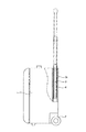
従来の旅行用かばん1は、図1に示されているように、運搬の便利性のために下部に多数のキャスター2が装着され、一側面には取っ手手段3が装着される。
As shown in FIG. 1, the
取っ手手段3は、かばん1の内部の一側面に引込み及び引出し可能なように装着され、かばん1の内部には取っ手手段3が引込み可能なように保存空間が備えられた支持手段4が形成される。このとき、取っ手手段3は、多数の管3aが連結された構造からなっていて伸縮可能であり、支持手段4により段階別に固定状態を維持できるという特徴がある。
The handle means 3 is attached to one side of the inside of the
かばん1を移動させようとする場合には、取っ手手段3を腰付近まで伸張させて手で把持し、かばん1を地面に対して斜めに傾けた状態でキャスター2を回転させることによって運搬する。
In order to move the
しかし、このような従来のかばん1に装着される取っ手手段3は、図1に示されているように、支持手段4がかばん1内部の一側面の底部から上端部まで延びるように形成されていて設置空間を大きく占めるため、かばん1内部の荷物を収納する空間がその分だけ減少するといった問題点がある。
However, as shown in FIG. 1, the handle means 3 attached to such a
また、取っ手手段3は、通常2段階乃至3段階に長さ調節が可能な構造からなるため、多様なユーザーの身長に適合するように引出される長さを調節するには限界がある。 Further, since the handle means 3 has a structure in which the length can be adjusted usually in two to three stages, there is a limit in adjusting the length to be pulled out so as to adapt to the heights of various users.
本発明は、上記のような問題点を勘案して案出されたものであり、その目的は、取っ手手段が設けられる設置空間を縮小させることができる折畳み式取っ手及びこれを備えたかばんを提供することにある。 The present invention has been devised in view of the above problems, and its purpose is to provide a foldable handle that can reduce the installation space in which the handle means is provided, and a bag equipped with the foldable handle. There is to do.
本発明の他の目的は、取っ手手段が引出される長さを多様に調節できるようにして使用の便宜性を高める折畳み式取っ手及びこれを備えたかばんを提供することにある。 It is another object of the present invention to provide a foldable handle and a bag provided with the foldable handle which can adjust the length with which the handle means is pulled out in various ways to improve the convenience of use.
上記のような本発明の目的を達成するための折畳み式取っ手及びこれを備えたかばんは、折畳まれたり広げられたりしながら伸縮可能に中央部を基準に二つのリンクが互いに交差するように連結されるリンク組立体の端にもう一つのリンク組立体が連結され、その一端がかばんに支持される折畳み手段;及び、上記折畳み手段の他端に装着され、ユーザーが手で把持するための取っ手手段;を含む構造から構成される。 The foldable handle and the bag provided with the foldable handle for achieving the object of the present invention as described above can be expanded and contracted so that the two links intersect with each other based on the central portion. Folding means having another link assembly connected to the end of the link assembly to be connected, one end of which is supported by a bag; and a folding means which is attached to the other end of the folding means and is held by a user's hand A structure including handle means.
また、上記取っ手手段は、所定の位置にスライド孔が貫通された取っ手ハウジング;及び、上記スライド孔に沿ってスライド可能に、上記スライド孔の両端部のうちの少なくとも一端部に装着され、上記折畳み手段の他端が回動可能に連結される固定バー;から構成される。 The handle means includes a handle housing having a slide hole penetrated at a predetermined position; and is mounted on at least one end portion of the slide hole so as to be slidable along the slide hole. A fixing bar to which the other end of the means is rotatably connected.
また、上記取っ手手段には、上記折畳み手段が任意の長さだけ引出された状態を一時的に維持できるように、上記取っ手ハウジングの中間部に装着されて上記固定バーの動きを一時的に固定させる固定手段がさらに含まれる。 Further, the handle means is temporarily attached to the middle portion of the handle housing to temporarily fix the movement of the fixing bar so that the folding means can be temporarily maintained in a state where the folding means is pulled out by an arbitrary length. A fixing means is further included.
このように本発明による折畳み式取っ手は、折畳み手段が折畳まれたり広げられたりする構造的特徴を有していて、従来の構造に比べてかばんに設けられる設置空間が縮小されることによりかばんにより多くの物を収納できるようになるため、製品の性能が向上するという効果がある。 As described above, the folding handle according to the present invention has a structural feature that the folding means is folded or unfolded, and the bag is reduced by reducing the installation space provided in the bag as compared with the conventional structure. Since more items can be stored, there is an effect that the performance of the product is improved.
また、本発明による折畳み式取っ手は、取っ手手段に装着される固定手段により、ユーザーの所望通りに折畳み手段の引出される長さ調節が可能で、どの位置でも引出された状態を一時的に固定させることが可能になるため、使用の便宜性が高まるという効果がある。 In addition, the folding handle according to the present invention can be adjusted by the fixing means attached to the gripping means, and the length of the folding means can be adjusted as desired by the user, and temporarily fixed at any position. Therefore, the convenience of use is improved.
以下、添付図面を参照しながら、本発明の望ましい実施例による折畳み式取っ手及びこれを備えたかばんをより詳しく説明する。 Hereinafter, a foldable handle and a bag having the same according to a preferred embodiment of the present invention will be described in more detail with reference to the accompanying drawings.
図2は本発明の望ましい第1実施例による折畳み式取っ手及びこれを備えたかばんを示した斜視図であり、図3は折畳み式取っ手を示した分解斜視図、図4は折畳み手段が折畳まれて引込まれた状態を示した状態図、図5は折畳み手段が広げられた状態を示した状態図、図6は固定バーがスライドする状態を示した断面図、図7はピニオンギアが固定された状態を示した断面図、図8はピニオンギアの固定が解除された状態を示した断面図、そして、図9は支持手段のスライド板が作動する状態を示した断面図である。 FIG. 2 is a perspective view showing a foldable handle and a bag having the foldable handle according to the first preferred embodiment of the present invention, FIG. 3 is an exploded perspective view showing the foldable handle, and FIG. FIG. 5 is a state diagram showing a state in which the folding means is unfolded, FIG. 6 is a sectional view showing a state in which the fixing bar slides, and FIG. 7 is a view showing the pinion gear fixed. FIG. 8 is a cross-sectional view showing a state in which the pinion gear is unlocked, and FIG. 9 is a cross-sectional view showing a state in which the slide plate of the support means is operated.
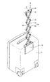
図示されているように、本発明の望ましい第1実施例による折畳み式取っ手及びこれを備えたかばんは、かばん1の一側面の上端部に装着される支持手段10と、支持手段10に一端が固定される折畳み手段20と、折畳み手段20の他端に装着されて、ユーザーが手で把持するための取っ手手段30と、折畳み手段20がユーザーの所望の長さだけ引出された状態を一時的に固定させる固定手段40とからなる。
As shown in the drawing, the folding handle according to the first preferred embodiment of the present invention and the bag equipped with the same include a supporting
折畳み手段20は、第1リンク21と第2リンク22が互いに交差するように中央部を互いに回動可能に固定する回動ピン23が装着されてリンク組立体24をなす。第1リンク21及び第2リンク22の端部に、もう一つのリンク組立体24をなす第1リンク21及び第2リンク22の端が回動ピン23により回動可能に固定される。上記のような方法によって多数のリンク組立体24が連結される。この時、第1リンク21及び第2リンク22は、隣合う第1リンク21及び第2リンク22とそれぞれの移動軌跡が互いに重なるように連結されて、リンク組立体24が折畳まれる場合は隣合うリンク組立体24同士その一部が互いに重なるようになる。
The folding means 20 is provided with a
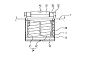
支持手段10は、かばん1の内部に引き込まれて設置されたり外部に装着されたりでき、着脱可能に装着されるのが望ましい。図示されてはいないが、着脱方法は、ボルトを締結して固定する方式や固定クランプなどを用いる方式など、多様に具現されることができる。
The supporting
支持手段10は、折畳み手段20が収納されるように一側が開口された収納空間11aが備えられ、かばん1の外周面の上端部に着脱可能に装着されるケース11と、ケース11の開口部11bに対向する収納空間に装着されるガイドレール12と、ガイドレール12に形成されたレール12aに沿ってスライド可能に装着され、一側面に長さ方向に沿って配列される多数の歯からなるラックギア部13aが形成されたスライド板13とから構成される。
The support means 10 is provided with a
この時、図示されてはいないが、第1リンク21の端部はスライド板13に結合されて、そのスライドと同時に回動可能で、第2リンク22の端部はケース11の底面部に回動可能なようにヒンジ結合されて、折畳み手段20が折畳まれたり広げられたりできるように支持する構造から構成されることも可能であるが、図示されているようにガイドレール12が相互平行に対をなして装着されることが望ましい。
At this time, although not shown, the end portion of the
また、図示されているように、支持手段10は、それぞれのラックギア部13aと噛み合えるように各スライド板13の間に回転可能に装着される固定ピニオンギア14と、スライド板13に固定され、折畳み手段20が位置する方向に延びて、第1リンク21又は第2リンク22の端がそれぞれ回動可能にヒンジ結合される間隔保持板15とをさらに含んで構成される。
Further, as shown in the figure, the support means 10 is fixed to the
取っ手手段30は、一側にスライド孔31aが貫通された取っ手ハウジング31と、スライド孔31aの両端にスライド可能に装着され、取っ手ハウジング31の外部に露出される端に折畳み手段20の他端が回動可能に連結される固定バー32とからなる。即ち、第1リンク21と第2リンク22の端が固定バー32にヒンジ結合されるのである。また、取っ手ハウジング31と固定バー32との間には管状のカバー33がそれぞれ装着され、また、それぞれのカバー33には他の部品との干渉を回避するために溝33aが形成され、各固定バー32の間には固定手段40が介在する。
The handle means 30 is slidably mounted on both ends of the
この時、図示されてはいないが、固定バー32がスライド孔31aの両端のうちの一方にだけ装着され、第1リンク21の端部は固定バー32に連結されて、そのスライドと同時に回動可能で、第2リンク22の端部は取っ手ハウジング31に回動可能なようにヒンジ結合されて、折畳み手段20が折畳まれたり広げられたりできるように支持する構造から構成されることも可能であるが、図示されているように固定バー32が対をなすように装着されるのが望ましい。
At this time, although not shown, the
固定手段40は、長さ方向に沿って歯が形成され、その一端が固定バー32に固定された一対のラックギア41と、各ラックギア41に同時に歯合可能に各ラックギア41の間に装着され、一側面に少なくとも一つの固定溝42aが形成されたピニオンギア42と、ピニオンギア42を回転可能に固定して、その一端部には固定溝42aに一時的に挿入可能な固定突起43aが形成されたピニオン軸43と、ピニオン軸43の一端を弾持する弾性部材44と、ピニオン軸43の他端が固定され、取っ手ハウジング31に形成されるボタンホール31bを通って上端部が外部に露出される固定ボタン45とからなる。
The fixing means 40 is mounted between a pair of
上記のように構成された本発明の望ましい第1実施例による折畳み式取っ手は、図4及び図5に示されているように折畳み手段20をなす各リンク組立体24が互いに折畳まれたり広げられたりしながらケース11の収納空間11aに引込まれたり引出されたりする。
The foldable handle according to the first preferred embodiment of the present invention constructed as described above has a structure in which the link assemblies 24 forming the folding means 20 are folded or unfolded as shown in FIGS. While being pulled, it is drawn into or pulled out of the
この時、取っ手手段30及び固定手段40は、図6乃至図8に示されているように折畳み手段20が折畳まれると、固定バー32が取っ手ハウジング31の外部に突出する方向へ移動する。折畳み手段20が広げられると、固定バー32が取っ手ハウジング31の内部に引込まれる方向へ移動する。
At this time, the handle means 30 and the fixing means 40 move in a direction in which the
そして、固定バー32に装着されたそれぞれのラックギア41が、ピニオンギア42に同時に噛み合った状態であるため、固定バー30は取っ手ハウジング31の中央を基準に同じ間隔を維持しながらスライドする。
Since each
図7に示されているように、弾性部材44によりピニオン軸43が加圧されて、固定突起43aがピニオンギア42の固定溝42aに挿入された状態になれば、固定されたピニオン軸43によりピニオンギア42も回転停止状態となり、ピニオンギア42の回転が停止すれば、ラックギア41と連結された固定バー32も停止状態を維持するようになるため、折畳み手段20の長さが固定された状態を維持するようになる。即ち、折畳み手段20が一定の長さだけ広げられた状態ならば、その長さ状態を維持するようになるのである。
As shown in FIG. 7, when the
図8に示されているように、ユーザーが固定ボタン45を加圧すると、弾性部材44が変形しながらピニオン軸43が移動し、固定溝42aから固定突起43aが抜け出てピニオンギア42が回転可能な状態に切り換わる。ピニオンギア42の回転が可能になれば、ピニオンギア42に噛み合ったラックギア41に連結された固定バー32が移動可能になるため、折畳み手段20を折畳んだり広げたりできるようになる。即ち、固定状態が解除されて折畳み手段20の広げられる長さの調節が可能になるのである。固定ボタン45を加圧していた力を抜けば、弾性部材44の弾性力によりピニオン軸43が元通りに戻って図7に示されているように固定状態に切り換わる。
As shown in FIG. 8, when the user presses the
図9に示されているように、折畳み手段20の折畳まれたり広げられたりする動作に伴って、スライド板13が固定ピニオンギア14に噛み合った状態で互いに連動するため、中央部を中心に同じ間隔を維持してそれぞれのスライド板13が移動するのである。間隔保持板15は、折畳み手段20が固定ピニオンギア14に接触するのを防止する。
As the folding means 20 is folded or unfolded as shown in FIG. 9, the
同様に、本発明の望ましい第2実施例による折畳み式取っ手及びこれを備えたかばんは、図10乃至図12に示されているように、中央部が貫通された形状からなり、ユーザーが手で把持するための取っ手部131a、及び折畳み手段20の他端が挿入される連結部131bが備えられた取っ手ハウジング131と、連結部131bの内側面の両側に沿って互いに平行に装着される一対のガイドレール132と、折畳み手段20をなす第1リンク21及び第2リンク22の端が回動可能にヒンジ結合され、ガイドレール132に形成されたレール132aに沿ってそれぞれスライドして、互いに向かい合う面に長さ方向に沿って配列される多数の歯からなるラックギア部133aが形成された固定バー133と、各ラックギア部133aの間に装着されて、それぞれのラックギア部133aに同時に噛み合い、一側面に所定の深さで陥没される固定溝134aが少なくとも一つ形成されたピニオンギア134と、ピニオンギア134を回転可能に支持して、一端部に固定溝134aに挿入される固定突起135aが形成されたピニオン軸135と、ピニオン軸135が固定される固定部材136と、固定部材136を弾持する弾性部材137とからなる。
Similarly, the foldable handle according to the second preferred embodiment of the present invention and the bag equipped with the foldable handle have a shape in which the central portion is penetrated as shown in FIGS. A
固定部材136は、連結部131b側に位置し、ピニオン軸135が固定される支持部136aと、支持部136aから取っ手部131aまで延びる延長部136bと、延長部136bから突出して、取っ手ハウジング131の取っ手部131aの内側に形成されたボタンホール131cを通って突出された端部が露出する固定ボタン136cとからなる。弾性部材137は、その一側が支持部136aに接触され、他側が取っ手ハウジング131の内側面に支持される。即ち、支持部136aの上下面のうち、ピニオン軸135が装着された下面の反対である上面を弾性部材が支持するのである。
The fixing
その他、取っ手部材130が装着される折畳み手段20と支持手段10の構成及び作動は、本発明の望ましい第1実施例と同様である。
Other configurations and operations of the folding means 20 and the support means 10 to which the
上記のように構成された折畳み式取っ手は、図11に示されているように、弾性部材137により固定部材136が加圧されて、ピニオン軸135に形成された固定突起135aがピニオンギア134に形成された固定溝134aに挿入された状態になると、固定されたピニオン軸135によりピニオンギア134も回転停止状態になり、ピニオンギア134の回転が停止すると、ラックギア部133aが形成された固定バー133も停止状態を維持するようになるため、折畳み手段20が固定された状態を維持するようになる。即ち、折畳み手段20が一定の長さだけ広げられた状態であれば、その長さ状態を維持するようになるのである。
As shown in FIG. 11, the foldable handle configured as described above is configured such that the fixing
図12に示されているように、ユーザーが固定ボタン136cを加圧すると、弾性部材137が圧縮されながらピニオン軸135が移動し、固定溝134aから固定突起135aが抜け出てピニオンギア134が回転可能な状態に切り換わる。ピニオンギア134の回転が可能になれば、ピニオンギア134に噛み合ったラックギア部133aが形成された固定バー133が移動可能になるため、折畳み手段20を折り畳んだり広げたりできるようになる。即ち、固定が解除されて折畳み手段20の広げられる長さの調節が可能になるのである。固定ボタン136cを加圧していた力を抜けば、弾性部材137の弾性力によりピニオン軸135が戻って図11に示されているように固定状態に切り換わる。
As shown in FIG. 12, when the user presses the
同様に、本発明の望ましい第3実施例による折畳み式取っ手及びこれを備えたかばんは、図13乃至図15に示されているように構成される。 Similarly, a foldable handle and a bag provided with the same according to a third preferred embodiment of the present invention are configured as shown in FIGS.
同様に、本発明の望ましい第3実施例による折畳み式取っ手及びこれを備えたかばんは、図13乃至図15に示されているように構成される。 Similarly, a foldable handle and a bag provided with the same according to a third preferred embodiment of the present invention are configured as shown in FIGS.
支持手段210は、かばん1の内部に引き込まれて設置されたり外部に装着されたりでき、着脱可能に装着されるのが望ましい。図示されてはいないが、着脱方法は、ボルトを締結して固定する方式や固定クランプなどを用いる方式など、多様に具現されることができる。
The support means 210 can be installed by being pulled into the
また、支持手段210は、折畳み手段20が収納されるように一側が開口された収納空間211aが備えられ、かばん1の外周面の上端部に着脱可能に装着されるケース211と、折畳み手段20の一端に形成された第1リンク21及び第2リンク22に、一端が回動可能にヒンジ結合されるそれぞれの垂直リンク212と、各垂直リンク212の他端を相互連結し、回動可能に支持する垂直ピン213と、折畳み手段20の一端に形成された第1リンク21及び第2リンク22の端部に装着されるスライドピン214とから構成される。
Further, the support means 210 is provided with a storage space 211a that is open on one side so that the folding means 20 is stored, and a
ケース211の収納空間211aの内側面には、第1リンク21及び第2リンク22の中央部に装着される回動ピン23の両端が固定される固定溝215が形成され、固定溝215の下端部に所定の深さで陥没され、折畳み手段20の移動軌跡と平行をなすように延びて、垂直ピン213がスライド可能に挿入される垂直溝216が形成され、スライドピン214がスライド可能に嵌められることができるように、左右一対に所定の深さだけ陥没され、固定溝215を中心点とする弧状をなすように延びるスライド溝217が形成される。
A fixing
その他の支持手段210に装着される折畳み手段20及び取っ手手段30、130の構成及び作動は、本発明の望ましい第1実施例又は第2実施例と同一である。 Other configurations and operations of the folding means 20 and the handle means 30 and 130 attached to the support means 210 are the same as those of the first or second preferred embodiment of the present invention.
上記のように構成された支持手段210は、図14及び図15に示されているように、折畳み手段20が折畳まれたり広げられたりする動作に伴って垂直リンク212が回動され、垂直リンク212の回動に伴って垂直リンク212が垂直溝216に沿ってスライドする。垂直リンク212は、垂直溝216によってその移動が折畳み手段20の移動軌跡と平行をなすように制限されるため、折畳み手段20が引込み及び引出しされる場合に移動経路から外れないようになる。即ち、垂直ピン213は、その動きが垂直溝216によって制限されるため、折畳み手段20が引出された状態においてケース211に固定された回動ピン23を基準として左右に回動されないようになるのである。
As shown in FIGS. 14 and 15, the support means 210 configured as described above is configured such that the
同様に、本発明の望ましい第4実施例による折畳み式取っ手を構成する取っ手手段330は、図16乃至図18に示されているように、ユーザーが手で把持し、一側にスライド孔331aが貫通された取っ手ハウジング331と、スライド孔331aの両端にスライド可能に装着される内部ハウジング332と、内部ハウジング332の外部側の端に連結され、延びた端に折畳み手段20の他端が回動可能に連結される固定バー333とからなる。即ち、第1リンク21と第2リンク22の端が固定バー333にヒンジ結合されるのである。また、それぞれの固定バー333の中間部には固定手段340が介在する。
Similarly, as shown in FIGS. 16 to 18, the handle means 330 constituting the foldable handle according to the fourth preferred embodiment of the present invention is gripped by the user and has a
固定手段340は、それぞれの内部ハウジング332の端部に装着されるボールハウジング341と、ボールハウジング341に転がり可能に装着され、内部ハウジング332の中心に向かって突き出るスライドボール341aと、スライド孔331aの中央を基準に両側に装着され、外周面にはスライド孔331aの中央を基準に相互同一方向を有するスクリュー形状のスクリュー溝342aが形成されたスクリューシャフト342と、スクリューシャフト342を回転可能に支持するベアリング343と、内部ハウジング332が挿入され、取っ手ハウジング331の内部に回転可能に装着され、ベアリング343が固定されるカバー344と、それぞれのスクリューシャフト342の端に装着され、一時的に互いに接触可能で、各接触面345aに多数の摩擦突起が備えられたブレーキ345と、それぞれのブレーキ345とベアリング343との間に装着され、ブレーキ345を互いに接触する方向に加圧するスプリング346と、ブレーキ345の間に突き出た端が一時的に挿入されて、接触していたブレーキ345を分離させることができるようにピンハウジング347に移動可能に支持され、ブレーキ345が装着された位置とは反対方向に弾持される少なくとも1つの離隔ピン348と、取っ手ハウジング331の内側面の一定部位から所定の高さで突き出、一時的に離隔ピン348をブレーキ345の方向へ加圧する加圧突起331bとからなる。
The fixing means 340 includes a
また、スライドボール341aは、スクリューシャフト342を基準に等間隔で多数配列されるのが望ましく、スライドボール341aの個数と同一の個数だけスクリューシャフト342にスクリュー溝342aが形成される。離隔ピン348は、互いに対称をなすように180度間隔をおいて形成されるのが望ましく、離隔ピン348の位置に合わせて加圧突起331bも二箇所に形成される。また、離隔ピン348とピンハウジング347とが接触する間には圧縮スプリングが装着され、離隔ピン348を弾持するのが望ましい。
Further, it is desirable that a large number of
上記のように構成された本発明の望ましい第4実施例による折畳み式取っ手は、図17及び図18に示されているように、折畳み手段20が折畳まれると、固定バー333が取っ手ハウジング331の外部に引き出される方向へ移動する。折畳み手段20が長く広げられると、固定バー333が取っ手ハウジング331の内部に引込まれる方向へ移動する。
As shown in FIGS. 17 and 18, the folding handle according to the fourth preferred embodiment of the present invention constructed as described above is configured such that when the folding means 20 is folded, the fixing
また、第1リンク21及び第2リンク22が中央部に形成された回動ピン23を基準に折畳まれたり広げられたりするため、取っ手ハウジング331の両側に形成された固定バー333が取っ手ハウジング331の中央を基準に同一間隔を維持しながらスライドし、固定バー333に連結されたスライドボール341aが左右方向に移動するにつれて、スクリュー溝342aの形成されたそれぞれのスクリューシャフト342が同時に回転するようになるのである。
In addition, since the
折畳み手段20を広げようとする場合は、図17に示されているように、取っ手ハウジング331を回転させると加圧突起331bが離隔ピン348を加圧するようになり、離隔ピン348の突出部がブレーキ345の間に挟まれて、互いに接触していた接触面345aが分離しながら、それぞれのブレーキ345が回転可能な状態に切り換わる。
When the folding means 20 is to be expanded, as shown in FIG. 17, when the
上記のようにブレーキ345が互いに分離されて回転可能な状態になると、スクリューシャフト342が回転可能な状態になって、スクリュー溝342aに挟まれて固定されていたスライドボール341aが、回転するスクリュー溝342aに沿って転がりながら移動できるようになるため、折畳み手段20を広げたり折畳んだりできるようになる。即ち、密着していたブレーキ345が離隔ピン348によって分離されてそれぞれの回転が可能になると、固定状態が解除されて、折畳み手段20の長さ調整が可能になるのである。
As described above, when the
折畳み手段20を一定の長さに広げた状態で固定させようとする場合は、図18に示されているように、折畳み手段20を一定の長さに広げた状態で取っ手ハウジング331を反対方向に回転させると、離隔ピン348を加圧していた加圧突起331bが除去され、弾性力によって離隔ピン348が元の状態に戻りながらブレーキ345の間から外れる。離隔ピン348が外れると、それぞれのブレーキ345の接触面345aはスプリング346の弾性力によって互いに接触しながら摩擦突起がかみ合って回転が拘束され、それぞれのスクリューシャフト342が一体化されながら個別的回転が不可能な状態になる。上記のように、スクリューシャフト342の個別的回転が不可能になると、スクリュー溝342aにかみ合ったスライドボール341aの移動が制限されて固定バー333が固定された状態になり、それによって折畳み手段20が固定された状態を維持するようになる。即ち、固定バー333が外部に引き出されるためには、接触面345aを基準に両側のスクリューシャフト342が反時計回りに回転されなければならず、固定バー333が内部に引き込まれるためには、接触面345aを基準に両側のスクリューシャフト342が時計回りに回転されなければならないため、ブレーキ345が互いに密着して個別的回転が不可能になれば、両側のスクリューシャフト342の回転力が相殺されて、折畳み手段20が一定の長さに広げられた状態を維持するようになるのである。
When the folding means 20 is to be fixed in a state where it is expanded to a certain length, as shown in FIG. 18, the
本発明は、上述した特定の望ましい実施例に限定されるものではなく、特許請求範囲に記載された本発明の要旨を逸脱しない範囲内で、本発明の属する技術分野における通常の知識を有する者ならば誰でも多様な変形実施が可能であるのはもちろんのこと、そのような変更は特許請求範囲の範囲内にある。 The present invention is not limited to the specific preferred embodiments described above, but has ordinary knowledge in the technical field to which the present invention belongs without departing from the spirit of the present invention described in the claims. Anyone can make various modifications, and such modifications are within the scope of the claims.
10 支持手段
14 リンク組立体
20 折畳み手段
21 第1リンク
22 第2リンク
30、130 取っ手手段
40 固定手段
DESCRIPTION OF
Claims (18)
上記折畳み手段の他端に装着され、ユーザーが手で把持するための取っ手手段;を含むことを特徴とする折畳み式取っ手。 Another link assembly is connected to the end of the link assembly where the two links are connected so that they can extend and contract while being folded or unfolded, with one end in the bag Supported folding means; and
A foldable handle, comprising: a handle means attached to the other end of the foldable means for a user to hold by hand.
所定の位置にスライド孔が貫通された取っ手ハウジング;及び
上記スライド孔に沿ってスライド可能に、上記スライド孔の両端部のうちの少なくとも一端部に装着され、上記折畳み手段の他端が回動可能に連結される固定バー;を含むことを特徴とする請求項1に記載の折畳み式取っ手。 The handle means is
A handle housing having a slide hole penetrated at a predetermined position; and mounted on at least one end of both ends of the slide hole so as to be slidable along the slide hole, and the other end of the folding means is rotatable. The foldable handle according to claim 1, further comprising: a fixing bar coupled to the frame.
長さ方向に沿って歯が形成され、その一端が上記各固定バーに固定されたラックギア;及び
上記各ラックギアに同時に歯合可能に装着され、回転が制御されるピニオンギア;を含むことを特徴とする請求項4に記載の折畳み式取っ手。 The fixing means is
A rack gear in which teeth are formed along a length direction, and one end of which is fixed to each of the fixing bars; and a pinion gear that is mounted on the rack gears so as to be capable of meshing simultaneously and whose rotation is controlled. The foldable handle according to claim 4.
上記ピニオンギアを回転可能に固定し、一端部には上記ピニオンギアの一側面に少なくとも一つ形成される固定溝に一時的に挿入される固定突起が形成されたピニオン軸;
上記固定突起が上記固定溝に挿入された状態を維持できるように、上記ピニオン軸の一端を支持する弾性部材;及び
上記ピニオン軸を加圧して上記固定突起が上記固定溝から一時的に抜け出るように上記ピニオン軸の他端が固定され、上記取っ手ハウジングの外部に上端部が露出される固定ボタン;を更に含むことを特徴とする請求項5に記載の折畳み式取っ手。 The fixing means is
A pinion shaft that rotatably fixes the pinion gear, and has a fixed projection that is temporarily inserted into a fixing groove formed on at least one side surface of the pinion gear at one end;
An elastic member that supports one end of the pinion shaft so as to maintain the state where the fixing protrusion is inserted into the fixing groove; and pressurizing the pinion shaft so that the fixing protrusion temporarily comes out of the fixing groove. The foldable handle according to claim 5, further comprising: a fixing button to which the other end of the pinion shaft is fixed and an upper end portion is exposed to the outside of the handle housing.
それぞれの上記固定バーに連結され、上記取っ手ハウジングのスライド孔の内部に引き込まれる内部ハウジング;
上記内部ハウジングの端部に、中心点に向かって突き出、転がり可能に装着されたスライドボール;
上記取っ手ハウジングのスライド孔の中央を基準に両側にそれぞれ装着され、外周面に上記スライドボールを案内するスクリュー溝が上記スライド孔の中央を基準に相互同一方向に形成されたスクリューシャフト;
上記スクリューシャフトを回転可能に支持するベアリング;
上記取っ手ハウジングの内部に回転可能に装着され、上記ベアリングが固定されるカバー;
上記スクリューシャフトの端に、一時的に相互接触可能なようにそれぞれ装着されるブレーキ;
上記ブレーキが相互接触した状態を維持可能なように上記ブレーキを弾持するスプリング;
上記ブレーキの間に一時的に挿入されて、上記ブレーキを所定の間隔だけ離隔させることができるように上記ブレーキの間に装着され、上記ブレーキの間から外れる方向に弾持される離隔ピン;及び
上記取っ手ハウジングが回転すると共に、一時的に上記離隔ピンを上記ブレーキの間に加圧可能なように、上記取っ手ハウジングの内側面の一定部位から突き出る加圧突起;を含むことを特徴とする請求項4に記載の折畳み式取っ手。 The fixing means is
An internal housing connected to each of the fixed bars and drawn into a slide hole of the handle housing;
A slide ball mounted on the end of the inner housing so as to protrude toward the center point and to be able to roll;
Screw shafts mounted on both sides with respect to the center of the slide hole of the handle housing, and screw grooves for guiding the slide ball formed on the outer peripheral surface in the same direction with respect to the center of the slide hole;
A bearing that rotatably supports the screw shaft;
A cover rotatably mounted inside the handle housing and to which the bearing is fixed;
Brakes respectively mounted on the ends of the screw shafts so as to be temporarily contactable with each other;
A spring that holds the brake so that the brake can maintain contact with each other;
A separation pin that is temporarily inserted between the brakes and mounted between the brakes so that the brakes can be separated from each other by a predetermined distance; And a pressure protrusion protruding from a predetermined portion of the inner surface of the handle housing so that the handle housing rotates and the separation pin can be temporarily pressed between the brakes. Item 5. The foldable handle according to Item 4.
中央部が貫通された形状からなり、ユーザーが把持するための取っ手部、及び上記リンク組立体の端が挿入される連結部が備えられた取っ手ハウジング;
上記取っ手ハウジングの連結部に沿って装着される一対のガイドレール;
上記リンク組立体の他端が回動可能に結合され、上記ガイドレールに沿ってそれぞれスライドして、互いに向かい合う面に長さ方向に沿って配列される歯からなるラックギア部が形成された固定バー;
上記各固定バーのラックギア部に同時に噛み合って回転可能に上記各ラックギア部の間に装着され、一側面に少なくとも一つの固定溝が形成されたピニオンギア;
上記ピニオンギアを回転可能に支持し、一端部に上記固定溝に一時的に挿入される固定突起が形成されたピニオン軸;
上記ピニオン軸の他端が固定される支持部と、上記支持部から上記取っ手部まで延びる延長部と、ユーザーが加圧することによって上記固定突起が上記固定溝から一時的に抜け出るように上記延長部から上記取っ手ハウジングの中央部方向に突出し、突出された端が上記取っ手ハウジングの外部に露出される固定ボタンとが備えられた固定部材;及び
上記固定突起が上記固定溝に挿入された状態を維持できるように上記ピニオン軸が突出された方向の反対方向から上記固定部材を支持する弾性部材;を含むことを特徴とする請求項1に記載の折畳み式取っ手。 The handle means is
A handle housing having a shape with a central portion penetrating therein, and a handle portion for a user to hold, and a connecting portion into which an end of the link assembly is inserted;
A pair of guide rails mounted along the connecting portion of the handle housing;
A fixed bar in which the other end of the link assembly is rotatably coupled, slides along the guide rail, and has a rack gear portion formed of teeth arranged along the length direction on surfaces facing each other. ;
A pinion gear that is meshed with the rack gear portions of the fixed bars at the same time and is rotatably mounted between the rack gear portions and has at least one fixed groove formed on one side surface;
A pinion shaft that rotatably supports the pinion gear and has a fixed protrusion formed at one end portion thereof that is temporarily inserted into the fixed groove;
A support portion to which the other end of the pinion shaft is fixed; an extension portion extending from the support portion to the handle portion; and the extension portion so that the fixing protrusion temporarily comes out of the fixing groove when a user pressurizes the pinion shaft. A fixing member provided with a fixing button that protrudes from the handle housing toward the center of the handle housing and whose protruding end is exposed to the outside of the handle housing; and maintains the state in which the fixing protrusion is inserted into the fixing groove The foldable handle according to claim 1, further comprising: an elastic member that supports the fixing member from a direction opposite to a direction in which the pinion shaft protrudes.
第1リンク及び第2リンクの中央部を互いに回動可能に固定する回動ピンが装着されて多数の上記リンク組立体をなし、上記第1リンク及び上記第2リンクの端部にもう一つのリンク組立体をなす第1リンク及び第2リンクの端が回動ピンによって回動可能に連結され、上記第1リンク及び第2リンクは、隣合う第1リンク及び第2リンクと移動軌跡が互いに重なるように連結されて、上記収納空間に引込まれる時は隣合う上記リンク組立体の一部が互いに重畳されることを特徴とする請求項1に記載の折畳み式取っ手。 The folding means is
A rotation pin for rotatably fixing the central portion of the first link and the second link is mounted to form a plurality of link assemblies, and another end is provided at the end of the first link and the second link. The ends of the first link and the second link forming the link assembly are pivotally connected by a pivot pin, and the first link and the second link have movement trajectories with the adjacent first link and second link. 2. The foldable handle according to claim 1, wherein the foldable handles are connected so as to overlap each other and a part of the link assemblies adjacent to each other are overlapped when pulled into the storage space.
上記折畳み手段の引込みが可能なように一側が開口された、上記収納空間が備えられ、上記かばんの外周面に着脱可能に装着されるケース;
上記ケースの開口部に対向する収納空間の底面に少なくとも一つ装着されるガイドレール;及び
上記折畳み手段の一端が回動可能に固定され、上記ガイドレールに沿ってスライドする少なくとも一つのスライド板;を含むことを特徴とする請求項11に記載の折畳み式取っ手。 The support means is
A case provided with the storage space having one side opened so that the folding means can be retracted and detachably attached to the outer peripheral surface of the bag;
At least one guide rail mounted on the bottom surface of the storage space facing the opening of the case; and at least one slide plate on which one end of the folding means is rotatably fixed and slides along the guide rail; The foldable handle according to claim 11, comprising:
上記折畳み手段の引込みが可能なように一側が開口された、上記収納空間が備えられ、上記折畳み手段の一端に形成された各リンクの中央部を回動可能に支持する回動ピンが上記収納空間の内部に固定され、上記かばんの外周面に着脱可能に装着されるケース;
上記折畳み手段の一端に形成された各リンクに、一端が回動可能に結合される垂直リンク;及び
それぞれの上記垂直リンクの他端を回動可能に支持し、上記ケースの内側面に上記折畳み手段の移動軌跡と平行をなすように延びる垂直溝に沿ってスライドする垂直ピン;を含むことを特徴とする請求項11に記載の折畳み式取っ手。 The support means is
The storage space is provided with the storage space opened on one side so that the folding means can be retracted, and a rotation pin that rotatably supports the center of each link formed at one end of the folding means is the storage. A case fixed inside the space and detachably attached to the outer peripheral surface of the bag;
A vertical link whose one end is rotatably coupled to each link formed at one end of the folding means; and the other end of each vertical link is rotatably supported, and is folded on the inner surface of the case. 12. A foldable handle according to claim 11, comprising a vertical pin that slides along a vertical groove extending parallel to the movement trajectory of the means.
上記ケースに取付けられる上記回動ピンを中心点とする弧状をなすように左右一対に陥没されるスライド溝に沿ってスライドし、上記折畳み手段の一端に形成された各リンクの端に装着されるスライドピンをさらに含むことを特徴とする請求項16に記載の折畳み式取っ手。 The support means is
It slides along a slide groove recessed into a pair of left and right so as to form an arc shape with the pivot pin attached to the case as a center point, and is attached to the end of each link formed at one end of the folding means. The foldable handle according to claim 16, further comprising a slide pin.
折畳まれたり広げられたりしながら上記収納空間に引込み及び引出し可能に中央部を基準に二つのリンクが互いに交差するように連結されるリンク組立体の端にもう一つのリンク組立体が連結され、その一端が上記支持手段の内部に支持される折畳み手段;及び
上記折畳み手段の他端に装着され、ユーザーが手で把持するための取っ手手段;を含むことを特徴とする折畳み式取っ手を備えたかばん。 Support means formed in a part of the bag and provided with a storage space inside;
Another link assembly is connected to the end of the link assembly that is connected so that the two links intersect each other with respect to the central portion so that the storage space can be retracted and pulled out while being folded or unfolded. A folding handle having one end supported inside the supporting means; and a grip means attached to the other end of the folding means for a user to hold by hand. Takaban.
Applications Claiming Priority (2)
| Application Number | Priority Date | Filing Date | Title |
|---|---|---|---|
| KR10-2008-0030244 | 2008-04-01 | ||
| KR20080030244 | 2008-04-01 |
Publications (2)
| Publication Number | Publication Date |
|---|---|
| JP2009247883A JP2009247883A (en) | 2009-10-29 |
| JP4686576B2 true JP4686576B2 (en) | 2011-05-25 |
Family
ID=40957589
Family Applications (1)
| Application Number | Title | Priority Date | Filing Date |
|---|---|---|---|
| JP2008169223A Expired - Fee Related JP4686576B2 (en) | 2008-04-01 | 2008-06-27 | Folding handle and bag equipped with it |
Country Status (4)
| Country | Link |
|---|---|
| US (1) | US7934289B2 (en) |
| EP (1) | EP2106717B1 (en) |
| JP (1) | JP4686576B2 (en) |
| CN (1) | CN101548813B (en) |
Families Citing this family (7)
| Publication number | Priority date | Publication date | Assignee | Title |
|---|---|---|---|---|
| ITTV20090137A1 (en) * | 2009-06-26 | 2010-12-27 | Gianbattista Causin | TROLLEY SUITCASE |
| KR100960077B1 (en) * | 2010-03-16 | 2010-05-31 | 주식회사 캐리맥스통상 | Bag with handle part improving precision of expansion and contraction length |
| DE202014101684U1 (en) * | 2014-04-09 | 2015-07-20 | Ernst Kraemer & Söhne GmbH & Co. KG | Transport handle for attachment to a packaging |
| US10405644B2 (en) * | 2015-09-11 | 2019-09-10 | Nevaan Kothari | Hold a dental cleaning device on food related accessories |
| US20170086555A1 (en) * | 2015-09-28 | 2017-03-30 | Biogenesys, Inc. | Space-saving suitcase handle assemblies |
| CN111838918B (en) * | 2020-08-26 | 2022-03-22 | 广东锦锐旅行用品有限公司 | Suitcase capable of changing using state by utilizing lifting intelligence |
| CN113786130B (en) * | 2021-09-27 | 2023-02-24 | 上海高仙自动化科技发展有限公司 | Handle module and cleaning robot |
Citations (1)
| Publication number | Priority date | Publication date | Assignee | Title |
|---|---|---|---|---|
| JP2004344355A (en) * | 2003-05-21 | 2004-12-09 | Swany Corp | Bag with wheels |
Family Cites Families (12)
| Publication number | Priority date | Publication date | Assignee | Title |
|---|---|---|---|---|
| FR956119A (en) * | 1950-01-26 | |||
| US1628563A (en) * | 1925-07-20 | 1927-05-10 | Taylor John | Battery-plate puller |
| US2653826A (en) * | 1951-03-20 | 1953-09-29 | Lu Yen-Shen | Portable foldable shopping basket |
| US3112135A (en) * | 1961-04-03 | 1963-11-26 | Salomonson Conrad | Handy extending grip |
| FR1401689A (en) * | 1964-06-26 | 1965-06-04 | Little devil bending to several easements | |
| FR2272574A7 (en) * | 1974-05-20 | 1975-12-19 | Roussel Etienne | Collapsible suitcase trolley with lazy tongs handle - is locked in extended position by ring with handle folding over |
| DE2653316A1 (en) * | 1976-11-24 | 1978-06-01 | Franz Ritter | Expanding chimney pot grab - has handle at end furthest from shoe arm attachment point, with release eye |
| US4109952A (en) * | 1977-02-09 | 1978-08-29 | Michel Monzain | Package lifter |
| GB2111917A (en) * | 1981-07-16 | 1983-07-13 | Angus Christopher Firth | Trolley |
| CN1201632A (en) | 1997-10-27 | 1998-12-16 | 陈平和 | Pulling rod and positioner of suitcase and manufacture thereof |
| KR100322564B1 (en) | 1998-03-20 | 2002-07-02 | 윤종용 | Developing ink supplying apparatus for electrographic printer |
| WO2002071886A1 (en) * | 2001-02-22 | 2002-09-19 | Yoshiaki Tamura | Folding travel bag with cart |
-
2008
- 2008-06-19 US US12/142,513 patent/US7934289B2/en not_active Expired - Fee Related
- 2008-06-20 EP EP08252145A patent/EP2106717B1/en not_active Not-in-force
- 2008-06-27 JP JP2008169223A patent/JP4686576B2/en not_active Expired - Fee Related
- 2008-07-18 CN CN2008101265964A patent/CN101548813B/en not_active Expired - Fee Related
Patent Citations (1)
| Publication number | Priority date | Publication date | Assignee | Title |
|---|---|---|---|---|
| JP2004344355A (en) * | 2003-05-21 | 2004-12-09 | Swany Corp | Bag with wheels |
Also Published As
| Publication number | Publication date |
|---|---|
| EP2106717A2 (en) | 2009-10-07 |
| CN101548813A (en) | 2009-10-07 |
| US20090242342A1 (en) | 2009-10-01 |
| JP2009247883A (en) | 2009-10-29 |
| EP2106717B1 (en) | 2012-05-16 |
| CN101548813B (en) | 2012-08-29 |
| EP2106717A3 (en) | 2011-07-20 |
| US7934289B2 (en) | 2011-05-03 |
Similar Documents
| Publication | Publication Date | Title |
|---|---|---|
| JP4686576B2 (en) | Folding handle and bag equipped with it | |
| US20100283227A1 (en) | Service cart | |
| US8214972B2 (en) | Control handle of a retractable handle assembly for travel bag | |
| JP5301342B2 (en) | Folding wheelbarrow | |
| JP5279494B2 (en) | Storage unit | |
| US9408449B1 (en) | Stepless retractable handle assembly for luggage | |
| EP2888968A1 (en) | Carrying case | |
| US20220039529A1 (en) | Luggage with support | |
| JP2016514611A (en) | Retractable wheel mechanism | |
| EP2467040A2 (en) | Case having a housing and a sliding tray | |
| KR200467778Y1 (en) | Chest expander | |
| KR100950500B1 (en) | A handle with extendable arm and a bag having the same | |
| CN207579894U (en) | A kind of multi-purpose wheelbarrow | |
| JP6851898B2 (en) | Caster device on the workbench | |
| KR100539466B1 (en) | Foldable table | |
| JP5069990B2 (en) | Step and storage | |
| KR20190030823A (en) | Carrier having folding chair handle | |
| KR200492853Y1 (en) | Folding cart for carrying | |
| JP6021295B2 (en) | Sliding handles for silver cars and carry bags | |
| CN217446914U (en) | Inclined-pulling type folding vegetable buying vehicle | |
| CN211559525U (en) | Tool showing stand | |
| CN213550182U (en) | Tool pull rod bag convenient to carry | |
| JP3922035B2 (en) | Drawer storage device | |
| RU2282964C1 (en) | Foldable bench | |
| CN206501880U (en) | A kind of baby carriage and its armrest connecting device |
Legal Events
| Date | Code | Title | Description |
|---|---|---|---|
| A131 | Notification of reasons for refusal |
Free format text: JAPANESE INTERMEDIATE CODE: A131 Effective date: 20101012 |
|
| A521 | Request for written amendment filed |
Free format text: JAPANESE INTERMEDIATE CODE: A523 Effective date: 20101215 |
|
| TRDD | Decision of grant or rejection written | ||
| A01 | Written decision to grant a patent or to grant a registration (utility model) |
Free format text: JAPANESE INTERMEDIATE CODE: A01 Effective date: 20110118 |
|
| A01 | Written decision to grant a patent or to grant a registration (utility model) |
Free format text: JAPANESE INTERMEDIATE CODE: A01 |
|
| A61 | First payment of annual fees (during grant procedure) |
Free format text: JAPANESE INTERMEDIATE CODE: A61 Effective date: 20110214 |
|
| FPAY | Renewal fee payment (event date is renewal date of database) |
Free format text: PAYMENT UNTIL: 20140218 Year of fee payment: 3 |
|
| R150 | Certificate of patent or registration of utility model |
Free format text: JAPANESE INTERMEDIATE CODE: R150 |
|
| LAPS | Cancellation because of no payment of annual fees |