JP4686205B2 - Connection structure of sheet metal member and other members - Google Patents
Connection structure of sheet metal member and other members Download PDFInfo
- Publication number
- JP4686205B2 JP4686205B2 JP2005037366A JP2005037366A JP4686205B2 JP 4686205 B2 JP4686205 B2 JP 4686205B2 JP 2005037366 A JP2005037366 A JP 2005037366A JP 2005037366 A JP2005037366 A JP 2005037366A JP 4686205 B2 JP4686205 B2 JP 4686205B2
- Authority
- JP
- Japan
- Prior art keywords
- positioning
- side wall
- sheet metal
- metal member
- plate portion
- Prior art date
- Legal status (The legal status is an assumption and is not a legal conclusion. Google has not performed a legal analysis and makes no representation as to the accuracy of the status listed.)
- Expired - Fee Related
Links
Images


Description
本発明は、板金部材と他の部材(例えば他の板金部材)との連結構造に関する。 The present invention relates to a connection structure between a sheet metal member and another member (for example, another sheet metal member).
特許文献1には、板金部材であるシャシーの側板部と、他の部材(他の板金部材)である摺動棚との連結構造が開示されている。側板部には、曲げ加工により内側向きに直角に突設させられた2個の当て部材と、3個の螺子孔と、2個の位置決め孔(位置決め用孔)とが形成されている。摺動棚はL形の横断面形状を有し、その垂直面部分には、3個の螺子孔が形成されかつ、2個の位置決め突起(位置決め用突起)が、外側向きに突出するよう形成されている。摺動棚の、該側板部への取付の際には、まず、その下端部を該当て部材に仮置きし、垂直面部分を、該側板部にあてがうと、螺子孔の各々に、該螺子孔の各々が略合致する。そこで、これらの螺子孔に、それぞれ螺子を螺入すると、摺動棚が、該側板部に押しつけられ、それにつれて、該位置決め突起の各々が、該側板部の位置決め孔に自然に嵌入し、摺動棚の位置決めがなされる。 Patent Document 1 discloses a connection structure between a side plate portion of a chassis that is a sheet metal member and a sliding shelf that is another member (another sheet metal member). The side plate portion is formed with two abutting members, three screw holes, and two positioning holes (positioning holes) that are projected at right angles inward by bending. The sliding shelf has an L-shaped cross-sectional shape, and three screw holes are formed in a vertical surface portion thereof, and two positioning protrusions (positioning protrusions) are formed so as to protrude outward. Has been. When the sliding shelf is attached to the side plate portion, first, the lower end portion thereof is temporarily placed on the corresponding member, and the vertical surface portion is applied to the side plate portion. Each of the holes approximately matches. Therefore, when screws are respectively screwed into these screw holes, the sliding shelf is pressed against the side plate portion, and accordingly, each of the positioning protrusions is naturally fitted into the positioning hole of the side plate portion, The moving shelf is positioned.
上記連結構造においては、位置決め突起の各々の突出量が大きく、したがって位置合せは比較的容易である、しかしながら、位置決め突起の各々を形成する板部の面積が小さいなどの理由から深絞りができない場合には、半抜き又はバーリングにより位置決め突起を形成する。半抜き又はバーリングにより形成した位置決め突起の、該片面からの突出量は少ないので、板金部材と他の部材との位置合せが困難であり、位置決め突起が位置決め孔の周縁の一部領域に乗り上げた状態で締結されるおそれがある。また、上記連結構造において、摺動棚の、該側板部への取り付けの際には、まず、その下端部を該当て部材に仮置きするが、仮置きした状態で摺動棚を保持する必要があり、螺子による締結作業が困難である。
本発明の目的は、半抜き又はバーリングにより形成された位置決め突起を有する板金部材を、位置決め突起に対応して形成された位置決め穴を有する他の部材に対し、容易かつ確実に位置決めして連結することを可能にする、新規な板金部材と他の部材との連結構造を提供することである。 An object of the present invention is to easily and reliably position and connect a sheet metal member having a positioning protrusion formed by half punching or burring to another member having a positioning hole formed corresponding to the positioning protrusion. It is to provide a connection structure between a new sheet metal member and another member that makes it possible.
本発明の他の目的は、半抜き又はバーリングにより形成された位置決め突起を有する板金部材を、位置決め突起に対応して形成された位置決め穴を有する他の部材に対し、容易かつ確実に位置決めすることができ、しかも簡単な作業で連結することを可能にする、新規な板金部材と他の部材との連結構造を提供することである。 Another object of the present invention is to easily and reliably position a sheet metal member having a positioning projection formed by half punching or burring with respect to another member having a positioning hole formed corresponding to the positioning projection. It is possible to provide a connection structure between a new sheet metal member and another member that can be connected by a simple operation.
本発明によれば、
板金部材と他の部材との連結構造において、板金部材は、一端と他端との間を延在する平板部を備え、平板部の一端には、一端から平板部の延在方向に延び出す仮位置決め突起と、一端から直角に延びるフランジとが形成され、フランジには、半抜き又はバーリングにより形成された一端位置決め突起及び雌ねじ穴が形成され、平板部の他端には、他端から平板部の延在方向に延び出す他端位置決め突起が形成され、他の部材は、相互に間隔をおいて対向する一対の側壁からなり、片方の側壁には、仮位置決め突起に対応して仮位置決め支持穴が、一端位置決め突起に対応して位置決め穴が、雌ねじ穴に対応して取付穴が、それぞれ形成され、他方の側壁には、他端位置決め突起に対応して位置決め支持穴が形成され、板金部材の平板部の他端は、他端位置決め突起を他方の側壁の位置決め支持穴に嵌合して支持することにより、他方の側壁の所定の位置に支持され、板金部材の平板部の一端は、仮位置決め突起を片方の側壁の仮位置決め支持穴に嵌合して仮支持することにより、片方の側壁における仮位置に仮支持され、該仮支持により相互に整合される片方の側壁の取付穴と板金部材の雌ねじ穴に取付穴から雄ねじ部材を挿入締結することにより、板金部材の一端位置決め突起が片方の側壁の位置決め穴に嵌合して、板金部材が片方の側壁の所定の位置に締結される、ことを特徴とする板金部材と他の部材との連結構造、が提供される。
板金部材の平板部の一端におけるフランジの該仮位置決め突起及び片方の側壁の該仮位置決め支持穴は、それぞれ、1個形成されると共に横断面が長方形をなし、該仮位置決め支持穴の幅及び長さは、それぞれ、該仮位置決め突起の幅及び長さよりもわずかに大きく形成され、該フランジに形成された該一端位置決め突起及び片方の側壁の該位置決め穴は、それぞれ、2個形成され、該一端位置決め突起の各々は円形の周縁を有し、片方の側壁に形成された片方の該位置決め穴は円形の内周面を有すると共に片方の該一端位置決め突起の外径と実質的に同じ又はわずかに大きな内径を有し、片方の側壁に形成された他方の該位置決め穴は、他方の該一端位置決め突起の外径と実質的に同じ又はわずかに大きな幅を備えた長穴から形成される、ことが好ましい。
板金部材の平板部の他端における該他端位置決め突起及び他方の側壁の該位置決め支持穴は、それぞれ、2個形成されると共に横断面が長方形をなし、該位置決め支持穴の幅及び長さは、それぞれ、該他端位置決め突起の幅及び長さよりもわずかに大きく形成されている、ことが好ましい。
該側壁の各々は画像形成装置の定着装置に配設され、該側壁の各々には、発熱源が内蔵された熱ローラと、熱ローラに圧接される圧ローラとが回転自在に支持され、板金部材の平板部は、熱ローラの外周面に対し間隔をおいて熱ローラの軸方向に延在するよう配置され、該平板部には、熱ローラの外周面の温度に対応して該発熱源と電源とを接続する電気回路をON−OFFするサーモスタットが、熱ローラの外周面に隙間をおいて対向するよう配設されている、ことが好ましい。
According to the present invention,
In the coupling structure of the sheet metal member and the other member, the sheet metal member is provided with a flat plate portion extending between one end and the other end, to one end of the flat plate portion extends in the extending direction of the flat plate portion from one end A temporary positioning protrusion to be extended and a flange extending at a right angle from one end are formed. One end positioning protrusion and a female screw hole formed by half punching or burring are formed on the flange, and the other end of the flat plate portion is formed from the other end. The other end positioning projection extending in the extending direction of the flat plate portion is formed, and the other member is composed of a pair of side walls facing each other with a space therebetween, and one side wall has a temporary positioning projection corresponding to the temporary positioning projection. A positioning support hole is formed corresponding to the one end positioning projection, a positioning hole is formed corresponding to the female screw hole, and a mounting support hole is formed corresponding to the other end positioning projection on the other side wall. , Other than the flat part of sheet metal members Is supported at a predetermined position on the other side wall by fitting and supporting the other end positioning projection in the positioning support hole on the other side wall, and one end of the flat plate portion of the sheet metal member has the temporary positioning projection on one side. By fitting and temporarily supporting the temporary positioning support hole on the side wall, it is temporarily supported at a temporary position on one side wall, and the mounting hole on one side wall and the female screw hole on the sheet metal member that are aligned with each other by the temporary support. By inserting and fastening the male screw member from the mounting hole, the one-end positioning projection of the sheet metal member is fitted into the positioning hole on one side wall, and the sheet metal member is fastened at a predetermined position on one side wall. A connection structure between a sheet metal member and another member is provided .
The temporary positioning support hole of the flange provisional positioning projection and one side wall of the one end of the flat plate portion of the sheet metal members, respectively, without a cross-section with the one formed rectangular, the width of the temporary positioning support hole and Each of the lengths is formed to be slightly larger than the width and length of the temporary positioning protrusion, and the one end positioning protrusion formed on the flange and the two positioning holes on one side wall are respectively formed. Each of the one end positioning protrusions has a circular peripheral edge, and one of the positioning holes formed in one side wall has a circular inner peripheral surface and is substantially the same as or slightly the outer diameter of the one end positioning protrusion. The other positioning hole formed on one side wall is formed from an elongated hole having a width substantially the same as or slightly larger than the outer diameter of the other one-end positioning protrusion, It is preferable.
The positioning support hole of the other end positioning projection and the other side wall at the other end of the flat plate portion of the plate member, respectively, without a cross-section with the two form a rectangular, the width and length of the positioning support hole , respectively, are slightly larger than the width and length of the other end positioning projection, it is preferable.
Each of the side walls is disposed in a fixing device of the image forming apparatus, and each of the side walls is rotatably supported by a heat roller having a built-in heat source and a pressure roller pressed against the heat roller. The flat plate portion of the member is disposed so as to extend in the axial direction of the heat roller at a distance from the outer peripheral surface of the heat roller, and the flat plate portion includes the heat source corresponding to the temperature of the outer peripheral surface of the heat roller. It is preferable that a thermostat for turning on and off an electric circuit connecting the power source and the power source is arranged to face the outer peripheral surface of the heat roller with a gap.
以下、本発明に従って構成された板金部材と他の部材との連結構造の実施の形態であって、画像形成装置の定着装置に適用された実施形態を、添付図面を参照して詳細に説明する。 Hereinafter, an embodiment of a connection structure between a sheet metal member and another member configured according to the present invention and applied to a fixing device of an image forming apparatus will be described in detail with reference to the accompanying drawings. .
図1を参照して、定着装置2は、細長く延在する底壁4と、底壁4の長手方向両端部から直立して相互に対向するよう底壁4に配設された一対の側壁6及び8とを備えている。側壁6及び8間には、後述するとおりにして、板金部材10が離脱自在に装着される。側壁6及び8間には、ハロゲンヒータなどの図示しない発熱源が内蔵された熱ローラ12と、熱ローラ12に圧接される圧ローラ14とが回転自在に支持されている。板金部材10は、一端(図1において左端)と他端(図1において右端)との間を直線状に延在する平板部10Aを備えている。平板部10Aは、熱ローラ12の外周面に対し間隔をおいて熱ローラ12の軸方向に延在するよう配置され、平板部10Aには、熱ローラ12の外周面の温度に対応して該発熱源と電源とを接続する電気回路(いずれも図示せず)をON−OFFするサーモスタットSが、熱ローラ12の外周面に対向するよう配設されている。板金部材10に対し、一対の側壁6及び8は他の部材を構成する。
Referring to FIG. 1, a fixing device 2 includes a bottom wall 4 that is elongated and a pair of
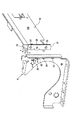
次に、定着装置2に適用された本発明による、板金部材10と他の部材である一対の側壁6及び8との連結構造の実施の形態について詳細に説明する。図3及び図4を参照して、板金部材10の平板部10Aの一端における、図3及び図4において上端には、一端から平板部10Aの延在方向に直線状に延び出す1個の仮位置決め突起20が一体に形成されている。また、平板部10Aの一端における、仮位置決め突起20よりも図3において下方領域には、一端から直角に折り曲げられて延び出すフランジ22が形成されている。仮位置決め突起20は、図4に示されているように、横断面が、幅x、及び幅xに直交する縦方向長さyであって幅xよりも幾分長い長さyを有する長方形をなしている。幅xは、平板部10の板厚と同じでありかつ、板厚方向と一致している。
Next, an embodiment of a connection structure between the
フランジ22は、平板部10Aの延在方向に見て長方形をなし、その両面は、平板部10Aの延在方向に直交している。フランジ22には、半抜き又はバーリング、実施形態においては半抜きにより形成された複数個の、実施形態においては2個の位置決め突起24、25及び1個の雌ねじ穴26が形成されている。平板部10Aの一端に形成された一端位置決め突起である位置決め突起24及び25は、図3及び図4において上下方向に間隔をおいて形成されている。相互に実質的に同じ構成を有する位置決め突起24及び25の各々は、フランジ22の外面から突出するよう形成され、それぞれ円形の周縁を有している。雌ねじ穴26は、位置決め突起24の各々の中間位置に形成されている。
The
片方の側壁6は、板金から一体に形成されかつ平板部6Aを有している。平板部6Aには、板金部材10に形成された上記1個の仮位置決め突起20、2個の位置決め突起24、25及び1個の雌ねじ穴26に対応して、それぞれ、1個の仮位置決め支持穴28、2個の位置決め穴30、32、及び1個の取付穴34が形成されている。仮位置決め支持穴28は、図4に示されているように、横断面が、幅x+d、及び幅x+dに直交する縦方向長さy+dであって幅x+dよりも幾分長い縦方向長さy+dを有する長方形をなしている。このように、仮位置決め支持穴28の幅x+d及び縦方向長さy+dは、それぞれ、仮位置決め突起20の幅x及び縦方向長さyよりもわずかに(+dだけ)大きく形成されている。
One
片方の側壁6の平板部6Aに形成された位置決め穴30及び32のうち、片方の位置決め穴30(図3及び図4において上側に位置する位置決め穴30)は、円形の内周面を有すると共に片方の位置決め突起24(図3及び図4において上側に位置する位置決め突起24)の外径と実質的に同じ又はわずかに大きな内径を有している。また、平板部6Aに形成された他方の位置決め穴32(図3及び図4において下側に位置する位置決め穴32)は、他方の位置決め突起25(図3及び図4において下側に位置する位置決め突起25)の外径と実質的に同じ又はわずかに大きな幅を備えた長穴から形成されている。位置決め穴32の長穴の延在方向は、図3及び図4において上下方向である。
Of the
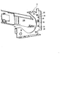
図2を参照して、板金部材10の平板部10Aの他端における、図2において上端及び下端には、他端から平板部10Aの延在方向に直線状に延び出す2個の位置決め突起40及び42が一体に形成されている。平板部10Aの他端に形成された他端位置決め突起である位置決め突起40及び42は、横断面が、仮位置決め突起20と同様な長方形をなしている。実施形態において、位置決め突起40及び42の長方形の幅は、平板部10Aの板厚と同じであり、したがって仮位置決め突起20と同じであるが、縦方向長さは仮位置決め突起20よりも大きく形成されている。
Referring to FIG. 2, at the other end of the
他方の側壁8は、板金から一体に形成されかつ平板部8Aを有している。平板部8Aには、板金部材10に形成された上記2個の位置決め突起40及び42に対応して、2個の位置決め支持穴44及び46が形成されている。位置決め支持穴44及び46は横断面が長方形をなし、位置決め支持穴44及び46の幅及び長さは、それぞれ、位置決め突起40及び42の幅及び長さよりもわずかに大きく形成されている。
The
図示の実施形態において、側壁6及び8は、定着装置2の底壁4の所定位置に、相互に対向して予め装着されている。図2を参照して、板金部材10を側壁6及び8に装着するには、先ず、板金部材10の平板部10Aの他端に形成された位置決め突起40及び42を、それぞれ、他方の側壁8の位置決め支持穴44及び46に嵌合して支持する。これにより、板金部材10の平板部10Aの他端は、他方の側壁8の所定の位置に離脱自在に支持される(図6参照)。
In the illustrated embodiment, the
続いて、図3及び図5を参照して、板金部材10の平板部10Aの一端に形成された仮位置決め突起20を、片方の側壁6の仮位置決め支持穴28に嵌合して仮支持する(図5(a)参照)。これにより、板金部材10の平板部10Aの一端は、片方の側壁6における仮位置に仮支持される。この仮支持動作は、板金部材10の平板部10Aの他端における位置決め突起40及び42が、他方の側壁8の位置決め支持穴44及び46に嵌合して支持された状態で、板金部材10の仮位置決め突起20を、片方の側壁6の仮位置決め支持穴28に向けて移動させることにより容易に遂行可能である。板金部材10の平板部10Aの他端に形成された位置決め突起40及び42は、それぞれ、他方の側壁8の位置決め支持穴44及び46に嵌合支持された状態で相対移動させられる。側壁6及び8間の間隔、板金部材10の全長(仮位置決め突起20の先端から位置決め突起40及び42の先端までの長さ)、仮位置決め突起20の突出量、位置決め突起40及び42の突出量などを適宜に設定することにより、上記嵌合動作は容易に可能となる。
Subsequently, referring to FIGS. 3 and 5, the
板金部材10の他端が他方の側壁8における所定の位置に支持されかつ、一端が、片方の側壁6における仮位置に仮支持された状態で、相互に整合される片方の側壁6の取付穴34と板金部材10の雌ねじ穴26に取付穴34から雄ねじ部材50を挿入して締め込みを開始する((図5(b)参照))。板金部材10の一端は、その仮位置決め突起20が、片方の側壁6の位置決め穴28に嵌合された状態でガイドされながら、片方の側壁6の平板部6Aに向って相対移動させられる。そして、該相対移動の途中において、板金部材10の位置決め突起24及び25が、それぞれ、片方の側壁6の位置決め穴30及び32に嵌合させられる((図5(c)参照))。この位置決め作用は、位置決め突起24及び25と位置決め穴30及び32との位置が最大限ずれても、位置決め突起24及び25の円形周縁に形成されている曲面が位置決め穴30及び32の環状のエッジ部に当接する範囲に収まるよう、仮位置決め突起20と位置決め穴28との間の上記隙間dを設定することによって、達成することができる。上記したように、位置決め突起24及び25が、それぞれ、位置決め穴30及び32に嵌合させられた時点で、板金部材10が片方の側壁6に対し所定の位置に位置付けられる。雄ねじ部材50を更に十分に締め込むことにより、板金部材10は片方の側壁6に対し所定の位置に締結される((図5(d)及び図7参照))。この状態で、仮位置決め突起20は、位置決め穴28との間に設けられた上記隙間により過剰な圧接が回避される。
Mounting holes in one
このように、本発明によれば、半抜き又はバーリングにより形成された位置決め突起24及び25を有する板金部材10を、位置決め突起24及び25に対応して形成された位置決め穴30及び32を有する片方の側壁6に対し、容易かつ確実に位置決めして連結することを可能にする。また、板金部材10を側壁6及び8間に仮支持した状態で締結作業を遂行できるので、簡単な作業で連結することを可能にする。本発明を画像形成装置の定着装置2に適用した場合には、板金部材10を、側壁6及び8に対し高い精度をもって装着できるので、板金部材10にサーモスタットSを配設した場合には、サーモスタットSと熱ローラ12の外周面との隙間を高い精度で設定できるので、正確な温度キャッチに基づいて適正な熱制御を行うことが容易に可能となる。
As described above, according to the present invention, the
2:定着装置
6:片方の側壁
8:他方の側壁
10:板金部材
10A:平板部
12:熱ローラ
14:圧ローラ
20:仮位置決め突起
22:フランジ
24、25、40、42:位置決め突起
26:雌ねじ穴
28:仮位置決め支持穴
30、32:位置決め穴
44、46:位置決め支持穴
50:雄ねじ部材
2: Fixing device 6: One side wall 8: The other side wall 10:
Claims (4)
板金部材は、一端と他端との間を延在する平板部を備え、平板部の一端には、一端から平板部の延在方向に延び出す仮位置決め突起と、一端から直角に延びるフランジとが形成され、フランジには、半抜き又はバーリングにより形成された一端位置決め突起及び雌ねじ穴が形成され、平板部の他端には、他端から平板部の延在方向に延び出す他端位置決め突起が形成され、
他の部材は、相互に間隔をおいて対向する一対の側壁からなり、片方の側壁には、仮位置決め突起に対応して仮位置決め支持穴が、一端位置決め突起に対応して位置決め穴が、雌ねじ穴に対応して取付穴が、それぞれ形成され、他方の側壁には、他端位置決め突起に対応して位置決め支持穴が形成され、
板金部材の平板部の他端は、他端位置決め突起を他方の側壁の位置決め支持穴に嵌合して支持することにより、他方の側壁の所定の位置に支持され、板金部材の平板部の一端は、仮位置決め突起を片方の側壁の仮位置決め支持穴に嵌合して仮支持することにより、片方の側壁における仮位置に仮支持され、該仮支持により相互に整合される片方の側壁の取付穴と板金部材の雌ねじ穴に取付穴から雄ねじ部材を挿入締結することにより、板金部材の一端位置決め突起が片方の側壁の位置決め穴に嵌合して、板金部材が片方の側壁の所定の位置に締結される、
ことを特徴とする板金部材と他の部材との連結構造。 In the coupling structure of the sheet metal member and the other member,
The sheet metal member includes a flat plate portion extending between one end and the other end, and at one end of the flat plate portion, a temporary positioning protrusion extending from the one end in the extending direction of the flat plate portion, and a flange extending at a right angle from the one end The flange is formed with one end positioning projection and female screw hole formed by half punching or burring, and the other end positioning projection extending from the other end in the extending direction of the flat plate portion at the other end of the flat plate portion Formed,
The other member is composed of a pair of side walls facing each other with a space therebetween, and one side wall has a temporary positioning support hole corresponding to the temporary positioning protrusion, and a positioning hole corresponding to the one end positioning protrusion, and the female screw. A mounting hole is formed corresponding to the hole, and a positioning support hole is formed on the other side wall corresponding to the other end positioning projection,
The other end of the flat plate portion of the sheet metal member is supported at a predetermined position on the other side wall by fitting the other end positioning projection into the positioning support hole on the other side wall and supporting it. The temporary positioning protrusions are temporarily supported by fitting into the temporary positioning support holes on one side wall, thereby temporarily supporting the temporary positioning at the temporary position on one side wall, and mounting the one side wall aligned with each other by the temporary support. By inserting and tightening the male screw member from the mounting hole into the female screw hole of the sheet metal member, the one end positioning projection of the sheet metal member is fitted into the positioning hole on one side wall, and the sheet metal member is placed at a predetermined position on the one side wall. To be concluded,
A connection structure between a sheet metal member and another member.
Priority Applications (1)
| Application Number | Priority Date | Filing Date | Title |
|---|---|---|---|
| JP2005037366A JP4686205B2 (en) | 2005-02-15 | 2005-02-15 | Connection structure of sheet metal member and other members |
Applications Claiming Priority (1)
| Application Number | Priority Date | Filing Date | Title |
|---|---|---|---|
| JP2005037366A JP4686205B2 (en) | 2005-02-15 | 2005-02-15 | Connection structure of sheet metal member and other members |
Publications (2)
| Publication Number | Publication Date |
|---|---|
| JP2006226307A JP2006226307A (en) | 2006-08-31 |
| JP4686205B2 true JP4686205B2 (en) | 2011-05-25 |
Family
ID=36987858
Family Applications (1)
| Application Number | Title | Priority Date | Filing Date |
|---|---|---|---|
| JP2005037366A Expired - Fee Related JP4686205B2 (en) | 2005-02-15 | 2005-02-15 | Connection structure of sheet metal member and other members |
Country Status (1)
| Country | Link |
|---|---|
| JP (1) | JP4686205B2 (en) |
Families Citing this family (5)
| Publication number | Priority date | Publication date | Assignee | Title |
|---|---|---|---|---|
| JP2010190271A (en) * | 2009-02-17 | 2010-09-02 | Hoya Corp | Mounting structure of component |
| JP5370099B2 (en) * | 2009-11-25 | 2013-12-18 | スズキ株式会社 | Component positioning structure |
| CN103629208A (en) * | 2012-08-25 | 2014-03-12 | 上海储谱实业有限公司 | Connecting structure |
| JP6350393B2 (en) | 2015-05-27 | 2018-07-04 | 京セラドキュメントソリューションズ株式会社 | Image forming apparatus |
| JP7424084B2 (en) | 2020-02-04 | 2024-01-30 | ブラザー工業株式会社 | Fusing device |
Citations (4)
| Publication number | Priority date | Publication date | Assignee | Title |
|---|---|---|---|---|
| JPS619613U (en) * | 1984-06-22 | 1986-01-21 | 株式会社日立製作所 | Plate member attachment mechanism |
| JPH11222081A (en) * | 1998-02-10 | 1999-08-17 | Ikeda Bussan Co Ltd | Mounting structure of molding roof for vehicle |
| JP2002229363A (en) * | 2001-01-31 | 2002-08-14 | Kyocera Corp | Fixing device for electrophotographic device |
| JP2004108456A (en) * | 2002-09-17 | 2004-04-08 | Denso Corp | Component mounting structure |
-
2005
- 2005-02-15 JP JP2005037366A patent/JP4686205B2/en not_active Expired - Fee Related
Patent Citations (4)
| Publication number | Priority date | Publication date | Assignee | Title |
|---|---|---|---|---|
| JPS619613U (en) * | 1984-06-22 | 1986-01-21 | 株式会社日立製作所 | Plate member attachment mechanism |
| JPH11222081A (en) * | 1998-02-10 | 1999-08-17 | Ikeda Bussan Co Ltd | Mounting structure of molding roof for vehicle |
| JP2002229363A (en) * | 2001-01-31 | 2002-08-14 | Kyocera Corp | Fixing device for electrophotographic device |
| JP2004108456A (en) * | 2002-09-17 | 2004-04-08 | Denso Corp | Component mounting structure |
Also Published As
| Publication number | Publication date |
|---|---|
| JP2006226307A (en) | 2006-08-31 |
Similar Documents
| Publication | Publication Date | Title |
|---|---|---|
| JP4686205B2 (en) | Connection structure of sheet metal member and other members | |
| US20100034612A1 (en) | Cage nut | |
| JP3956235B2 (en) | Implantable equipment | |
| JP2002276638A (en) | Sliding type clip nut | |
| JP2008005687A (en) | Box-fixing tool and its mounting method | |
| JP2008121949A (en) | Outdoor unit of air conditioner | |
| JP2008170096A (en) | Installation apparatus for air conditioner | |
| JP5001896B2 (en) | Cooling fan mounting structure | |
| JP3879047B2 (en) | Implantable equipment | |
| JP3129413U (en) | Handle structure | |
| KR100546934B1 (en) | Gas combustion device | |
| KR20110011799U (en) | Connector for rectangular pipe | |
| JP5319474B2 (en) | Wiring fixture mounting device | |
| JP4478041B2 (en) | Trunk holder set | |
| JP4808648B2 (en) | Battery temperature detection switch mounting structure | |
| JP3746908B2 (en) | Connecting member | |
| JP2008020106A (en) | Outdoor unit of air conditioner | |
| JP2008202338A (en) | Connection structure | |
| JPH0743621Y2 (en) | Thermocouple fitting | |
| JP3646555B2 (en) | Protective duct reinforcement plate | |
| JP6684443B2 (en) | Hot air heater | |
| JP4830780B2 (en) | Cable rack connection structure | |
| JP4359338B2 (en) | Fitting | |
| KR100405916B1 (en) | A halogen lamp socket | |
| JP4915085B2 (en) | Mounting plate for heat exchanger, air conditioner using the same, and method of assembling the air conditioner |
Legal Events
| Date | Code | Title | Description |
|---|---|---|---|
| A621 | Written request for application examination |
Free format text: JAPANESE INTERMEDIATE CODE: A621 Effective date: 20080130 |
|
| A977 | Report on retrieval |
Free format text: JAPANESE INTERMEDIATE CODE: A971007 Effective date: 20100121 |
|
| A131 | Notification of reasons for refusal |
Free format text: JAPANESE INTERMEDIATE CODE: A131 Effective date: 20100824 |
|
| A521 | Written amendment |
Free format text: JAPANESE INTERMEDIATE CODE: A523 Effective date: 20101021 |
|
| TRDD | Decision of grant or rejection written | ||
| A01 | Written decision to grant a patent or to grant a registration (utility model) |
Free format text: JAPANESE INTERMEDIATE CODE: A01 Effective date: 20110118 |
|
| A01 | Written decision to grant a patent or to grant a registration (utility model) |
Free format text: JAPANESE INTERMEDIATE CODE: A01 |
|
| A61 | First payment of annual fees (during grant procedure) |
Free format text: JAPANESE INTERMEDIATE CODE: A61 Effective date: 20110214 |
|
| FPAY | Renewal fee payment (event date is renewal date of database) |
Free format text: PAYMENT UNTIL: 20140218 Year of fee payment: 3 |
|
| R150 | Certificate of patent or registration of utility model |
Ref document number: 4686205 Country of ref document: JP Free format text: JAPANESE INTERMEDIATE CODE: R150 Free format text: JAPANESE INTERMEDIATE CODE: R150 |
|
| FPAY | Renewal fee payment (event date is renewal date of database) |
Free format text: PAYMENT UNTIL: 20140218 Year of fee payment: 3 |
|
| S533 | Written request for registration of change of name |
Free format text: JAPANESE INTERMEDIATE CODE: R313533 |
|
| FPAY | Renewal fee payment (event date is renewal date of database) |
Free format text: PAYMENT UNTIL: 20140218 Year of fee payment: 3 |
|
| R350 | Written notification of registration of transfer |
Free format text: JAPANESE INTERMEDIATE CODE: R350 |
|
| LAPS | Cancellation because of no payment of annual fees |