JP4684042B2 - LIGHT EMITTING ELEMENT, LIGHT EMITTING DEVICE, AND ELECTRONIC DEVICE - Google Patents
LIGHT EMITTING ELEMENT, LIGHT EMITTING DEVICE, AND ELECTRONIC DEVICE Download PDFInfo
- Publication number
- JP4684042B2 JP4684042B2 JP2005225832A JP2005225832A JP4684042B2 JP 4684042 B2 JP4684042 B2 JP 4684042B2 JP 2005225832 A JP2005225832 A JP 2005225832A JP 2005225832 A JP2005225832 A JP 2005225832A JP 4684042 B2 JP4684042 B2 JP 4684042B2
- Authority
- JP
- Japan
- Prior art keywords
- layer
- light
- emitting element
- light emitting
- emitting
- Prior art date
- Legal status (The legal status is an assumption and is not a legal conclusion. Google has not performed a legal analysis and makes no representation as to the accuracy of the status listed.)
- Expired - Fee Related
Links
- 239000000463 material Substances 0.000 claims description 111
- 229910000476 molybdenum oxide Inorganic materials 0.000 claims description 50
- PQQKPALAQIIWST-UHFFFAOYSA-N oxomolybdenum Chemical compound [Mo]=O PQQKPALAQIIWST-UHFFFAOYSA-N 0.000 claims description 50
- 239000004065 semiconductor Substances 0.000 claims description 48
- XLOMVQKBTHCTTD-UHFFFAOYSA-N Zinc monoxide Chemical group [Zn]=O XLOMVQKBTHCTTD-UHFFFAOYSA-N 0.000 claims description 14
- 150000001875 compounds Chemical class 0.000 claims description 14
- 239000011787 zinc oxide Substances 0.000 claims description 6
- XHCLAFWTIXFWPH-UHFFFAOYSA-N [O-2].[O-2].[O-2].[O-2].[O-2].[V+5].[V+5] Chemical compound [O-2].[O-2].[O-2].[O-2].[O-2].[V+5].[V+5] XHCLAFWTIXFWPH-UHFFFAOYSA-N 0.000 claims description 5
- 229910001935 vanadium oxide Inorganic materials 0.000 claims description 5
- 229910044991 metal oxide Inorganic materials 0.000 claims description 4
- 150000004706 metal oxides Chemical group 0.000 claims description 4
- PFNQVRZLDWYSCW-UHFFFAOYSA-N (fluoren-9-ylideneamino) n-naphthalen-1-ylcarbamate Chemical compound C12=CC=CC=C2C2=CC=CC=C2C1=NOC(=O)NC1=CC=CC2=CC=CC=C12 PFNQVRZLDWYSCW-UHFFFAOYSA-N 0.000 claims description 3
- GWEVSGVZZGPLCZ-UHFFFAOYSA-N Titan oxide Chemical compound O=[Ti]=O GWEVSGVZZGPLCZ-UHFFFAOYSA-N 0.000 claims description 3
- 239000005083 Zinc sulfide Substances 0.000 claims description 3
- 229910000428 cobalt oxide Inorganic materials 0.000 claims description 3
- IVMYJDGYRUAWML-UHFFFAOYSA-N cobalt(ii) oxide Chemical compound [Co]=O IVMYJDGYRUAWML-UHFFFAOYSA-N 0.000 claims description 3
- 229910000480 nickel oxide Inorganic materials 0.000 claims description 3
- GNRSAWUEBMWBQH-UHFFFAOYSA-N oxonickel Chemical compound [Ni]=O GNRSAWUEBMWBQH-UHFFFAOYSA-N 0.000 claims description 3
- OGIDPMRJRNCKJF-UHFFFAOYSA-N titanium oxide Inorganic materials [Ti]=O OGIDPMRJRNCKJF-UHFFFAOYSA-N 0.000 claims description 3
- 229910052984 zinc sulfide Inorganic materials 0.000 claims description 3
- DRDVZXDWVBGGMH-UHFFFAOYSA-N zinc;sulfide Chemical compound [S-2].[Zn+2] DRDVZXDWVBGGMH-UHFFFAOYSA-N 0.000 claims description 3
- 239000010410 layer Substances 0.000 description 470
- 239000010408 film Substances 0.000 description 98
- 239000000126 substance Substances 0.000 description 68
- 239000000758 substrate Substances 0.000 description 50
- IBHBKWKFFTZAHE-UHFFFAOYSA-N n-[4-[4-(n-naphthalen-1-ylanilino)phenyl]phenyl]-n-phenylnaphthalen-1-amine Chemical group C1=CC=CC=C1N(C=1C2=CC=CC=C2C=CC=1)C1=CC=C(C=2C=CC(=CC=2)N(C=2C=CC=CC=2)C=2C3=CC=CC=C3C=CC=2)C=C1 IBHBKWKFFTZAHE-UHFFFAOYSA-N 0.000 description 43
- 238000000034 method Methods 0.000 description 27
- 229910052782 aluminium Inorganic materials 0.000 description 26
- 239000010409 thin film Substances 0.000 description 23
- 230000005525 hole transport Effects 0.000 description 21
- VBVAVBCYMYWNOU-UHFFFAOYSA-N coumarin 6 Chemical compound C1=CC=C2SC(C3=CC4=CC=C(C=C4OC3=O)N(CC)CC)=NC2=C1 VBVAVBCYMYWNOU-UHFFFAOYSA-N 0.000 description 19
- 239000011229 interlayer Substances 0.000 description 19
- XUIMIQQOPSSXEZ-UHFFFAOYSA-N Silicon Chemical compound [Si] XUIMIQQOPSSXEZ-UHFFFAOYSA-N 0.000 description 18
- 229910052751 metal Inorganic materials 0.000 description 18
- 239000002184 metal Substances 0.000 description 18
- 229910052710 silicon Inorganic materials 0.000 description 18
- 239000010703 silicon Substances 0.000 description 18
- 229910052744 lithium Inorganic materials 0.000 description 17
- XAGFODPZIPBFFR-UHFFFAOYSA-N aluminium Chemical compound [Al] XAGFODPZIPBFFR-UHFFFAOYSA-N 0.000 description 16
- 230000003287 optical effect Effects 0.000 description 16
- SPDPTFAJSFKAMT-UHFFFAOYSA-N 1-n-[4-[4-(n-[4-(3-methyl-n-(3-methylphenyl)anilino)phenyl]anilino)phenyl]phenyl]-4-n,4-n-bis(3-methylphenyl)-1-n-phenylbenzene-1,4-diamine Chemical compound CC1=CC=CC(N(C=2C=CC(=CC=2)N(C=2C=CC=CC=2)C=2C=CC(=CC=2)C=2C=CC(=CC=2)N(C=2C=CC=CC=2)C=2C=CC(=CC=2)N(C=2C=C(C)C=CC=2)C=2C=C(C)C=CC=2)C=2C=C(C)C=CC=2)=C1 SPDPTFAJSFKAMT-UHFFFAOYSA-N 0.000 description 15
- UHOVQNZJYSORNB-UHFFFAOYSA-N Benzene Chemical compound C1=CC=CC=C1 UHOVQNZJYSORNB-UHFFFAOYSA-N 0.000 description 15
- WHXSMMKQMYFTQS-UHFFFAOYSA-N Lithium Chemical compound [Li] WHXSMMKQMYFTQS-UHFFFAOYSA-N 0.000 description 15
- 239000002585 base Substances 0.000 description 15
- 238000002347 injection Methods 0.000 description 14
- 239000007924 injection Substances 0.000 description 14
- 239000011521 glass Substances 0.000 description 13
- 230000008859 change Effects 0.000 description 12
- IJGRMHOSHXDMSA-UHFFFAOYSA-N nitrogen Substances N#N IJGRMHOSHXDMSA-UHFFFAOYSA-N 0.000 description 12
- -1 (N- (4- (N, N-di-m-tolylamino) phenyl) ) -N-phenylamino Chemical group 0.000 description 10
- 238000000862 absorption spectrum Methods 0.000 description 10
- 239000000956 alloy Substances 0.000 description 10
- 238000004519 manufacturing process Methods 0.000 description 10
- 239000011159 matrix material Substances 0.000 description 10
- BASFCYQUMIYNBI-UHFFFAOYSA-N platinum Chemical compound [Pt] BASFCYQUMIYNBI-UHFFFAOYSA-N 0.000 description 10
- 239000002356 single layer Substances 0.000 description 10
- 229910045601 alloy Inorganic materials 0.000 description 9
- 238000010549 co-Evaporation Methods 0.000 description 9
- 238000000151 deposition Methods 0.000 description 9
- VYPSYNLAJGMNEJ-UHFFFAOYSA-N silicon dioxide Inorganic materials O=[Si]=O VYPSYNLAJGMNEJ-UHFFFAOYSA-N 0.000 description 9
- PXHVJJICTQNCMI-UHFFFAOYSA-N Nickel Chemical compound [Ni] PXHVJJICTQNCMI-UHFFFAOYSA-N 0.000 description 8
- KDLHZDBZIXYQEI-UHFFFAOYSA-N Palladium Chemical compound [Pd] KDLHZDBZIXYQEI-UHFFFAOYSA-N 0.000 description 8
- 239000003990 capacitor Substances 0.000 description 8
- 239000010949 copper Substances 0.000 description 8
- 238000005530 etching Methods 0.000 description 8
- 239000012535 impurity Substances 0.000 description 8
- 229920005989 resin Polymers 0.000 description 8
- 239000011347 resin Substances 0.000 description 8
- TVIVIEFSHFOWTE-UHFFFAOYSA-K tri(quinolin-8-yloxy)alumane Chemical compound [Al+3].C1=CN=C2C([O-])=CC=CC2=C1.C1=CN=C2C([O-])=CC=CC2=C1.C1=CN=C2C([O-])=CC=CC2=C1 TVIVIEFSHFOWTE-UHFFFAOYSA-K 0.000 description 8
- 238000001771 vacuum deposition Methods 0.000 description 8
- 229910052581 Si3N4 Inorganic materials 0.000 description 7
- 238000002425 crystallisation Methods 0.000 description 7
- 230000008025 crystallization Effects 0.000 description 7
- 238000010438 heat treatment Methods 0.000 description 7
- 229910052739 hydrogen Inorganic materials 0.000 description 7
- 239000012212 insulator Substances 0.000 description 7
- 229910052757 nitrogen Inorganic materials 0.000 description 7
- 238000005192 partition Methods 0.000 description 7
- HQVNEWCFYHHQES-UHFFFAOYSA-N silicon nitride Chemical compound N12[Si]34N5[Si]62N3[Si]51N64 HQVNEWCFYHHQES-UHFFFAOYSA-N 0.000 description 7
- 229910052814 silicon oxide Inorganic materials 0.000 description 7
- RYGMFSIKBFXOCR-UHFFFAOYSA-N Copper Chemical compound [Cu] RYGMFSIKBFXOCR-UHFFFAOYSA-N 0.000 description 6
- ZOKXTWBITQBERF-UHFFFAOYSA-N Molybdenum Chemical compound [Mo] ZOKXTWBITQBERF-UHFFFAOYSA-N 0.000 description 6
- RTAQQCXQSZGOHL-UHFFFAOYSA-N Titanium Chemical compound [Ti] RTAQQCXQSZGOHL-UHFFFAOYSA-N 0.000 description 6
- 239000007983 Tris buffer Substances 0.000 description 6
- 229910021417 amorphous silicon Inorganic materials 0.000 description 6
- UFVXQDWNSAGPHN-UHFFFAOYSA-K bis[(2-methylquinolin-8-yl)oxy]-(4-phenylphenoxy)alumane Chemical compound [Al+3].C1=CC=C([O-])C2=NC(C)=CC=C21.C1=CC=C([O-])C2=NC(C)=CC=C21.C1=CC([O-])=CC=C1C1=CC=CC=C1 UFVXQDWNSAGPHN-UHFFFAOYSA-K 0.000 description 6
- 239000002131 composite material Substances 0.000 description 6
- 229910052802 copper Inorganic materials 0.000 description 6
- 230000005284 excitation Effects 0.000 description 6
- 239000007789 gas Substances 0.000 description 6
- 239000001257 hydrogen Substances 0.000 description 6
- 239000011777 magnesium Substances 0.000 description 6
- 229910052750 molybdenum Inorganic materials 0.000 description 6
- 239000011733 molybdenum Substances 0.000 description 6
- 229910052760 oxygen Inorganic materials 0.000 description 6
- 229910052709 silver Inorganic materials 0.000 description 6
- 229910052719 titanium Inorganic materials 0.000 description 6
- 239000010936 titanium Substances 0.000 description 6
- UFHFLCQGNIYNRP-UHFFFAOYSA-N Hydrogen Chemical compound [H][H] UFHFLCQGNIYNRP-UHFFFAOYSA-N 0.000 description 5
- 239000004642 Polyimide Substances 0.000 description 5
- NIXOWILDQLNWCW-UHFFFAOYSA-N acrylic acid group Chemical group C(C=C)(=O)O NIXOWILDQLNWCW-UHFFFAOYSA-N 0.000 description 5
- 229910052783 alkali metal Inorganic materials 0.000 description 5
- 150000001340 alkali metals Chemical class 0.000 description 5
- 229910052784 alkaline earth metal Inorganic materials 0.000 description 5
- 150000001342 alkaline earth metals Chemical class 0.000 description 5
- 239000011651 chromium Substances 0.000 description 5
- 239000010931 gold Substances 0.000 description 5
- 150000002894 organic compounds Chemical class 0.000 description 5
- 229920001721 polyimide Polymers 0.000 description 5
- 230000001681 protective effect Effects 0.000 description 5
- 230000002829 reductive effect Effects 0.000 description 5
- 238000007789 sealing Methods 0.000 description 5
- 239000003566 sealing material Substances 0.000 description 5
- 238000004544 sputter deposition Methods 0.000 description 5
- 238000007740 vapor deposition Methods 0.000 description 5
- 239000011701 zinc Substances 0.000 description 5
- IYZMXHQDXZKNCY-UHFFFAOYSA-N 1-n,1-n-diphenyl-4-n,4-n-bis[4-(n-phenylanilino)phenyl]benzene-1,4-diamine Chemical compound C1=CC=CC=C1N(C=1C=CC(=CC=1)N(C=1C=CC(=CC=1)N(C=1C=CC=CC=1)C=1C=CC=CC=1)C=1C=CC(=CC=1)N(C=1C=CC=CC=1)C=1C=CC=CC=1)C1=CC=CC=C1 IYZMXHQDXZKNCY-UHFFFAOYSA-N 0.000 description 4
- ZVFQEOPUXVPSLB-UHFFFAOYSA-N 3-(4-tert-butylphenyl)-4-phenyl-5-(4-phenylphenyl)-1,2,4-triazole Chemical compound C1=CC(C(C)(C)C)=CC=C1C(N1C=2C=CC=CC=2)=NN=C1C1=CC=C(C=2C=CC=CC=2)C=C1 ZVFQEOPUXVPSLB-UHFFFAOYSA-N 0.000 description 4
- DHDHJYNTEFLIHY-UHFFFAOYSA-N 4,7-diphenyl-1,10-phenanthroline Chemical compound C1=CC=CC=C1C1=CC=NC2=C1C=CC1=C(C=3C=CC=CC=3)C=CN=C21 DHDHJYNTEFLIHY-UHFFFAOYSA-N 0.000 description 4
- VIZUPBYFLORCRA-UHFFFAOYSA-N 9,10-dinaphthalen-2-ylanthracene Chemical compound C12=CC=CC=C2C(C2=CC3=CC=CC=C3C=C2)=C(C=CC=C2)C2=C1C1=CC=C(C=CC=C2)C2=C1 VIZUPBYFLORCRA-UHFFFAOYSA-N 0.000 description 4
- VFUDMQLBKNMONU-UHFFFAOYSA-N 9-[4-(4-carbazol-9-ylphenyl)phenyl]carbazole Chemical group C12=CC=CC=C2C2=CC=CC=C2N1C1=CC=C(C=2C=CC(=CC=2)N2C3=CC=CC=C3C3=CC=CC=C32)C=C1 VFUDMQLBKNMONU-UHFFFAOYSA-N 0.000 description 4
- XKRFYHLGVUSROY-UHFFFAOYSA-N Argon Chemical compound [Ar] XKRFYHLGVUSROY-UHFFFAOYSA-N 0.000 description 4
- XEEYBQQBJWHFJM-UHFFFAOYSA-N Iron Chemical compound [Fe] XEEYBQQBJWHFJM-UHFFFAOYSA-N 0.000 description 4
- QVGXLLKOCUKJST-UHFFFAOYSA-N atomic oxygen Chemical compound [O] QVGXLLKOCUKJST-UHFFFAOYSA-N 0.000 description 4
- GQVWHWAWLPCBHB-UHFFFAOYSA-L beryllium;benzo[h]quinolin-10-olate Chemical compound [Be+2].C1=CC=NC2=C3C([O-])=CC=CC3=CC=C21.C1=CC=NC2=C3C([O-])=CC=CC3=CC=C21 GQVWHWAWLPCBHB-UHFFFAOYSA-L 0.000 description 4
- 229910052792 caesium Inorganic materials 0.000 description 4
- 229910052791 calcium Inorganic materials 0.000 description 4
- 239000011575 calcium Substances 0.000 description 4
- 239000010406 cathode material Substances 0.000 description 4
- KPUWHANPEXNPJT-UHFFFAOYSA-N disiloxane Chemical class [SiH3]O[SiH3] KPUWHANPEXNPJT-UHFFFAOYSA-N 0.000 description 4
- 229910052749 magnesium Inorganic materials 0.000 description 4
- 239000000203 mixture Substances 0.000 description 4
- 239000001301 oxygen Substances 0.000 description 4
- YRZZLAGRKZIJJI-UHFFFAOYSA-N oxyvanadium phthalocyanine Chemical compound [V+2]=O.C12=CC=CC=C2C(N=C2[N-]C(C3=CC=CC=C32)=N2)=NC1=NC([C]1C=CC=CC1=1)=NC=1N=C1[C]3C=CC=CC3=C2[N-]1 YRZZLAGRKZIJJI-UHFFFAOYSA-N 0.000 description 4
- 238000005268 plasma chemical vapour deposition Methods 0.000 description 4
- 229910052697 platinum Inorganic materials 0.000 description 4
- 230000008569 process Effects 0.000 description 4
- 229910052761 rare earth metal Inorganic materials 0.000 description 4
- 150000002910 rare earth metals Chemical class 0.000 description 4
- 239000000565 sealant Substances 0.000 description 4
- 229910021332 silicide Inorganic materials 0.000 description 4
- FVBUAEGBCNSCDD-UHFFFAOYSA-N silicide(4-) Chemical compound [Si-4] FVBUAEGBCNSCDD-UHFFFAOYSA-N 0.000 description 4
- 230000003595 spectral effect Effects 0.000 description 4
- WFKWXMTUELFFGS-UHFFFAOYSA-N tungsten Chemical compound [W] WFKWXMTUELFFGS-UHFFFAOYSA-N 0.000 description 4
- 229910052721 tungsten Inorganic materials 0.000 description 4
- 239000010937 tungsten Substances 0.000 description 4
- IXHWGNYCZPISET-UHFFFAOYSA-N 2-[4-(dicyanomethylidene)-2,3,5,6-tetrafluorocyclohexa-2,5-dien-1-ylidene]propanedinitrile Chemical compound FC1=C(F)C(=C(C#N)C#N)C(F)=C(F)C1=C(C#N)C#N IXHWGNYCZPISET-UHFFFAOYSA-N 0.000 description 3
- VYZAMTAEIAYCRO-UHFFFAOYSA-N Chromium Chemical compound [Cr] VYZAMTAEIAYCRO-UHFFFAOYSA-N 0.000 description 3
- ATJFFYVFTNAWJD-UHFFFAOYSA-N Tin Chemical compound [Sn] ATJFFYVFTNAWJD-UHFFFAOYSA-N 0.000 description 3
- HCHKCACWOHOZIP-UHFFFAOYSA-N Zinc Chemical compound [Zn] HCHKCACWOHOZIP-UHFFFAOYSA-N 0.000 description 3
- 230000001413 cellular effect Effects 0.000 description 3
- 229910052804 chromium Inorganic materials 0.000 description 3
- 229910017052 cobalt Inorganic materials 0.000 description 3
- 239000010941 cobalt Substances 0.000 description 3
- GUTLYIVDDKVIGB-UHFFFAOYSA-N cobalt atom Chemical compound [Co] GUTLYIVDDKVIGB-UHFFFAOYSA-N 0.000 description 3
- 150000004696 coordination complex Chemical class 0.000 description 3
- 239000013078 crystal Substances 0.000 description 3
- 229910021419 crystalline silicon Inorganic materials 0.000 description 3
- 239000002274 desiccant Substances 0.000 description 3
- 230000006866 deterioration Effects 0.000 description 3
- 238000000295 emission spectrum Methods 0.000 description 3
- 239000000945 filler Substances 0.000 description 3
- PCHJSUWPFVWCPO-UHFFFAOYSA-N gold Chemical compound [Au] PCHJSUWPFVWCPO-UHFFFAOYSA-N 0.000 description 3
- 229910052737 gold Inorganic materials 0.000 description 3
- 238000005499 laser crystallization Methods 0.000 description 3
- 238000005259 measurement Methods 0.000 description 3
- 238000002156 mixing Methods 0.000 description 3
- 229910052759 nickel Inorganic materials 0.000 description 3
- 239000011368 organic material Substances 0.000 description 3
- 229910052763 palladium Inorganic materials 0.000 description 3
- 238000002161 passivation Methods 0.000 description 3
- IEQIEDJGQAUEQZ-UHFFFAOYSA-N phthalocyanine Chemical compound N1C(N=C2C3=CC=CC=C3C(N=C3C4=CC=CC=C4C(=N4)N3)=N2)=C(C=CC=C2)C2=C1N=C1C2=CC=CC=C2C4=N1 IEQIEDJGQAUEQZ-UHFFFAOYSA-N 0.000 description 3
- 229910052718 tin Inorganic materials 0.000 description 3
- 229910052725 zinc Inorganic materials 0.000 description 3
- QEPMORHSGFRDLW-UHFFFAOYSA-L zinc;2-(2-hydroxyphenyl)-3h-1,3-benzoxazole-2-carboxylate Chemical compound [Zn+2].OC1=CC=CC=C1C1(C([O-])=O)OC2=CC=CC=C2N1.OC1=CC=CC=C1C1(C([O-])=O)OC2=CC=CC=C2N1 QEPMORHSGFRDLW-UHFFFAOYSA-L 0.000 description 3
- DTZWGKCFKSJGPK-VOTSOKGWSA-N (e)-2-(2-methyl-6-(2-(1,1,7,7-tetramethyl-1,2,3,5,6,7-hexahydropyrido[3,2,1-ij]quinolin-9-yl)vinyl)-4h-pyran-4-ylidene)malononitrile Chemical compound O1C(C)=CC(=C(C#N)C#N)C=C1\C=C\C1=CC(C(CCN2CCC3(C)C)(C)C)=C2C3=C1 DTZWGKCFKSJGPK-VOTSOKGWSA-N 0.000 description 2
- KIAJWKWOKTWTIZ-UHFFFAOYSA-N 1,4-dioxonaphthalene-2,3-dicarbonitrile Chemical compound C1=CC=C2C(=O)C(C#N)=C(C#N)C(=O)C2=C1 KIAJWKWOKTWTIZ-UHFFFAOYSA-N 0.000 description 2
- BFTIPCRZWILUIY-UHFFFAOYSA-N 2,5,8,11-tetratert-butylperylene Chemical group CC(C)(C)C1=CC(C2=CC(C(C)(C)C)=CC=3C2=C2C=C(C=3)C(C)(C)C)=C3C2=CC(C(C)(C)C)=CC3=C1 BFTIPCRZWILUIY-UHFFFAOYSA-N 0.000 description 2
- STTGYIUESPWXOW-UHFFFAOYSA-N 2,9-dimethyl-4,7-diphenyl-1,10-phenanthroline Chemical compound C=12C=CC3=C(C=4C=CC=CC=4)C=C(C)N=C3C2=NC(C)=CC=1C1=CC=CC=C1 STTGYIUESPWXOW-UHFFFAOYSA-N 0.000 description 2
- UOCMXZLNHQBBOS-UHFFFAOYSA-N 2-(1,3-benzoxazol-2-yl)phenol zinc Chemical compound [Zn].Oc1ccccc1-c1nc2ccccc2o1.Oc1ccccc1-c1nc2ccccc2o1 UOCMXZLNHQBBOS-UHFFFAOYSA-N 0.000 description 2
- FQJQNLKWTRGIEB-UHFFFAOYSA-N 2-(4-tert-butylphenyl)-5-[3-[5-(4-tert-butylphenyl)-1,3,4-oxadiazol-2-yl]phenyl]-1,3,4-oxadiazole Chemical compound C1=CC(C(C)(C)C)=CC=C1C1=NN=C(C=2C=C(C=CC=2)C=2OC(=NN=2)C=2C=CC(=CC=2)C(C)(C)C)O1 FQJQNLKWTRGIEB-UHFFFAOYSA-N 0.000 description 2
- HONWGFNQCPRRFM-UHFFFAOYSA-N 2-n-(3-methylphenyl)-1-n,1-n,2-n-triphenylbenzene-1,2-diamine Chemical compound CC1=CC=CC(N(C=2C=CC=CC=2)C=2C(=CC=CC=2)N(C=2C=CC=CC=2)C=2C=CC=CC=2)=C1 HONWGFNQCPRRFM-UHFFFAOYSA-N 0.000 description 2
- OBAJPWYDYFEBTF-UHFFFAOYSA-N 2-tert-butyl-9,10-dinaphthalen-2-ylanthracene Chemical compound C1=CC=CC2=CC(C3=C4C=CC=CC4=C(C=4C=C5C=CC=CC5=CC=4)C4=CC=C(C=C43)C(C)(C)C)=CC=C21 OBAJPWYDYFEBTF-UHFFFAOYSA-N 0.000 description 2
- PZLZJGZGJHZQAU-UHFFFAOYSA-N 3-(4-tert-butylphenyl)-4-(4-ethylphenyl)-5-(4-phenylphenyl)-1,2,4-triazole Chemical compound C1=CC(CC)=CC=C1N1C(C=2C=CC(=CC=2)C(C)(C)C)=NN=C1C1=CC=C(C=2C=CC=CC=2)C=C1 PZLZJGZGJHZQAU-UHFFFAOYSA-N 0.000 description 2
- OGGKVJMNFFSDEV-UHFFFAOYSA-N 3-methyl-n-[4-[4-(n-(3-methylphenyl)anilino)phenyl]phenyl]-n-phenylaniline Chemical group CC1=CC=CC(N(C=2C=CC=CC=2)C=2C=CC(=CC=2)C=2C=CC(=CC=2)N(C=2C=CC=CC=2)C=2C=C(C)C=CC=2)=C1 OGGKVJMNFFSDEV-UHFFFAOYSA-N 0.000 description 2
- SCZWJXTUYYSKGF-UHFFFAOYSA-N 5,12-dimethylquinolino[2,3-b]acridine-7,14-dione Chemical compound CN1C2=CC=CC=C2C(=O)C2=C1C=C1C(=O)C3=CC=CC=C3N(C)C1=C2 SCZWJXTUYYSKGF-UHFFFAOYSA-N 0.000 description 2
- FCNCGHJSNVOIKE-UHFFFAOYSA-N 9,10-diphenylanthracene Chemical compound C1=CC=CC=C1C(C1=CC=CC=C11)=C(C=CC=C2)C2=C1C1=CC=CC=C1 FCNCGHJSNVOIKE-UHFFFAOYSA-N 0.000 description 2
- SXGIRTCIFPJUEQ-UHFFFAOYSA-N 9-anthracen-9-ylanthracene Chemical group C1=CC=CC2=CC3=CC=CC=C3C(C=3C4=CC=CC=C4C=C4C=CC=CC4=3)=C21 SXGIRTCIFPJUEQ-UHFFFAOYSA-N 0.000 description 2
- NLZUEZXRPGMBCV-UHFFFAOYSA-N Butylhydroxytoluene Chemical compound CC1=CC(C(C)(C)C)=C(O)C(C(C)(C)C)=C1 NLZUEZXRPGMBCV-UHFFFAOYSA-N 0.000 description 2
- MSDMPJCOOXURQD-UHFFFAOYSA-N C545T Chemical compound C1=CC=C2SC(C3=CC=4C=C5C6=C(C=4OC3=O)C(C)(C)CCN6CCC5(C)C)=NC2=C1 MSDMPJCOOXURQD-UHFFFAOYSA-N 0.000 description 2
- 229910004261 CaF 2 Inorganic materials 0.000 description 2
- OYPRJOBELJOOCE-UHFFFAOYSA-N Calcium Chemical compound [Ca] OYPRJOBELJOOCE-UHFFFAOYSA-N 0.000 description 2
- OKTJSMMVPCPJKN-UHFFFAOYSA-N Carbon Chemical compound [C] OKTJSMMVPCPJKN-UHFFFAOYSA-N 0.000 description 2
- QPLDLSVMHZLSFG-UHFFFAOYSA-N Copper oxide Chemical compound [Cu]=O QPLDLSVMHZLSFG-UHFFFAOYSA-N 0.000 description 2
- 239000005751 Copper oxide Substances 0.000 description 2
- 229910052691 Erbium Inorganic materials 0.000 description 2
- FYYHWMGAXLPEAU-UHFFFAOYSA-N Magnesium Chemical compound [Mg] FYYHWMGAXLPEAU-UHFFFAOYSA-N 0.000 description 2
- ZCQWOFVYLHDMMC-UHFFFAOYSA-N Oxazole Chemical compound C1=COC=N1 ZCQWOFVYLHDMMC-UHFFFAOYSA-N 0.000 description 2
- OAICVXFJPJFONN-UHFFFAOYSA-N Phosphorus Chemical compound [P] OAICVXFJPJFONN-UHFFFAOYSA-N 0.000 description 2
- 229910000577 Silicon-germanium Inorganic materials 0.000 description 2
- PPBRXRYQALVLMV-UHFFFAOYSA-N Styrene Chemical compound C=CC1=CC=CC=C1 PPBRXRYQALVLMV-UHFFFAOYSA-N 0.000 description 2
- FZWLAAWBMGSTSO-UHFFFAOYSA-N Thiazole Chemical compound C1=CSC=N1 FZWLAAWBMGSTSO-UHFFFAOYSA-N 0.000 description 2
- 229910052769 Ytterbium Inorganic materials 0.000 description 2
- LEVVHYCKPQWKOP-UHFFFAOYSA-N [Si].[Ge] Chemical compound [Si].[Ge] LEVVHYCKPQWKOP-UHFFFAOYSA-N 0.000 description 2
- MWPLVEDNUUSJAV-UHFFFAOYSA-N anthracene Chemical compound C1=CC=CC2=CC3=CC=CC=C3C=C21 MWPLVEDNUUSJAV-UHFFFAOYSA-N 0.000 description 2
- 229910052786 argon Inorganic materials 0.000 description 2
- 150000004982 aromatic amines Chemical class 0.000 description 2
- XZCJVWCMJYNSQO-UHFFFAOYSA-N butyl pbd Chemical compound C1=CC(C(C)(C)C)=CC=C1C1=NN=C(C=2C=CC(=CC=2)C=2C=CC=CC=2)O1 XZCJVWCMJYNSQO-UHFFFAOYSA-N 0.000 description 2
- TVFDJXOCXUVLDH-UHFFFAOYSA-N caesium atom Chemical compound [Cs] TVFDJXOCXUVLDH-UHFFFAOYSA-N 0.000 description 2
- 150000001716 carbazoles Chemical class 0.000 description 2
- 229910052799 carbon Inorganic materials 0.000 description 2
- 230000015556 catabolic process Effects 0.000 description 2
- 229910000431 copper oxide Inorganic materials 0.000 description 2
- XCJYREBRNVKWGJ-UHFFFAOYSA-N copper(II) phthalocyanine Chemical compound [Cu+2].C12=CC=CC=C2C(N=C2[N-]C(C3=CC=CC=C32)=N2)=NC1=NC([C]1C=CC=CC1=1)=NC=1N=C1[C]3C=CC=CC3=C2[N-]1 XCJYREBRNVKWGJ-UHFFFAOYSA-N 0.000 description 2
- 238000000354 decomposition reaction Methods 0.000 description 2
- 238000006731 degradation reaction Methods 0.000 description 2
- 238000007865 diluting Methods 0.000 description 2
- ZUOUZKKEUPVFJK-UHFFFAOYSA-N diphenyl Chemical compound C1=CC=CC=C1C1=CC=CC=C1 ZUOUZKKEUPVFJK-UHFFFAOYSA-N 0.000 description 2
- 238000001312 dry etching Methods 0.000 description 2
- UYAHIZSMUZPPFV-UHFFFAOYSA-N erbium Chemical compound [Er] UYAHIZSMUZPPFV-UHFFFAOYSA-N 0.000 description 2
- 238000001704 evaporation Methods 0.000 description 2
- 239000000284 extract Substances 0.000 description 2
- 230000002349 favourable effect Effects 0.000 description 2
- 125000001153 fluoro group Chemical group F* 0.000 description 2
- RBTKNAXYKSUFRK-UHFFFAOYSA-N heliogen blue Chemical compound [Cu].[N-]1C2=C(C=CC=C3)C3=C1N=C([N-]1)C3=CC=CC=C3C1=NC([N-]1)=C(C=CC=C3)C3=C1N=C([N-]1)C3=CC=CC=C3C1=N2 RBTKNAXYKSUFRK-UHFFFAOYSA-N 0.000 description 2
- 229910003437 indium oxide Inorganic materials 0.000 description 2
- PJXISJQVUVHSOJ-UHFFFAOYSA-N indium(iii) oxide Chemical compound [O-2].[O-2].[O-2].[In+3].[In+3] PJXISJQVUVHSOJ-UHFFFAOYSA-N 0.000 description 2
- AMGQUBHHOARCQH-UHFFFAOYSA-N indium;oxotin Chemical compound [In].[Sn]=O AMGQUBHHOARCQH-UHFFFAOYSA-N 0.000 description 2
- 239000011261 inert gas Substances 0.000 description 2
- 229910010272 inorganic material Inorganic materials 0.000 description 2
- 239000011147 inorganic material Substances 0.000 description 2
- 238000003780 insertion Methods 0.000 description 2
- 230000037431 insertion Effects 0.000 description 2
- 230000003993 interaction Effects 0.000 description 2
- 238000010030 laminating Methods 0.000 description 2
- 239000003446 ligand Substances 0.000 description 2
- 230000007774 longterm Effects 0.000 description 2
- 150000002739 metals Chemical class 0.000 description 2
- 239000013081 microcrystal Substances 0.000 description 2
- 150000004767 nitrides Chemical class 0.000 description 2
- 125000000962 organic group Chemical group 0.000 description 2
- 239000005416 organic matter Substances 0.000 description 2
- JMANVNJQNLATNU-UHFFFAOYSA-N oxalonitrile Chemical compound N#CC#N JMANVNJQNLATNU-UHFFFAOYSA-N 0.000 description 2
- 229910052698 phosphorus Inorganic materials 0.000 description 2
- 239000011574 phosphorus Substances 0.000 description 2
- 229920002120 photoresistant polymer Polymers 0.000 description 2
- 239000000049 pigment Substances 0.000 description 2
- 239000010453 quartz Substances 0.000 description 2
- 230000002441 reversible effect Effects 0.000 description 2
- 229910001925 ruthenium oxide Inorganic materials 0.000 description 2
- WOCIAKWEIIZHES-UHFFFAOYSA-N ruthenium(iv) oxide Chemical compound O=[Ru]=O WOCIAKWEIIZHES-UHFFFAOYSA-N 0.000 description 2
- 239000004332 silver Substances 0.000 description 2
- 229910052712 strontium Inorganic materials 0.000 description 2
- 238000012360 testing method Methods 0.000 description 2
- 229910052723 transition metal Inorganic materials 0.000 description 2
- 150000003624 transition metals Chemical class 0.000 description 2
- 238000001039 wet etching Methods 0.000 description 2
- NAWDYIZEMPQZHO-UHFFFAOYSA-N ytterbium Chemical compound [Yb] NAWDYIZEMPQZHO-UHFFFAOYSA-N 0.000 description 2
- YVTHLONGBIQYBO-UHFFFAOYSA-N zinc indium(3+) oxygen(2-) Chemical compound [O--].[Zn++].[In+3] YVTHLONGBIQYBO-UHFFFAOYSA-N 0.000 description 2
- GWDUZCIBPDVBJM-UHFFFAOYSA-L zinc;2-(2-hydroxyphenyl)-3h-1,3-benzothiazole-2-carboxylate Chemical compound [Zn+2].OC1=CC=CC=C1C1(C([O-])=O)SC2=CC=CC=C2N1.OC1=CC=CC=C1C1(C([O-])=O)SC2=CC=CC=C2N1 GWDUZCIBPDVBJM-UHFFFAOYSA-L 0.000 description 2
- OBMPIWRNYHXYBC-UHFFFAOYSA-N 1-n,1-n,3-n,3-n,5-n,5-n-hexakis(3-methylphenyl)benzene-1,3,5-triamine Chemical compound CC1=CC=CC(N(C=2C=C(C)C=CC=2)C=2C=C(C=C(C=2)N(C=2C=C(C)C=CC=2)C=2C=C(C)C=CC=2)N(C=2C=C(C)C=CC=2)C=2C=C(C)C=CC=2)=C1 OBMPIWRNYHXYBC-UHFFFAOYSA-N 0.000 description 1
- AWXGSYPUMWKTBR-UHFFFAOYSA-N 4-carbazol-9-yl-n,n-bis(4-carbazol-9-ylphenyl)aniline Chemical compound C12=CC=CC=C2C2=CC=CC=C2N1C1=CC=C(N(C=2C=CC(=CC=2)N2C3=CC=CC=C3C3=CC=CC=C32)C=2C=CC(=CC=2)N2C3=CC=CC=C3C3=CC=CC=C32)C=C1 AWXGSYPUMWKTBR-UHFFFAOYSA-N 0.000 description 1
- ZOXJGFHDIHLPTG-UHFFFAOYSA-N Boron Chemical compound [B] ZOXJGFHDIHLPTG-UHFFFAOYSA-N 0.000 description 1
- 241001101998 Galium Species 0.000 description 1
- GYHNNYVSQQEPJS-UHFFFAOYSA-N Gallium Chemical compound [Ga] GYHNNYVSQQEPJS-UHFFFAOYSA-N 0.000 description 1
- 101000837344 Homo sapiens T-cell leukemia translocation-altered gene protein Proteins 0.000 description 1
- 206010034972 Photosensitivity reaction Diseases 0.000 description 1
- 239000004695 Polyether sulfone Substances 0.000 description 1
- 238000001237 Raman spectrum Methods 0.000 description 1
- 229910003902 SiCl 4 Inorganic materials 0.000 description 1
- 102100028692 T-cell leukemia translocation-altered gene protein Human genes 0.000 description 1
- NRTOMJZYCJJWKI-UHFFFAOYSA-N Titanium nitride Chemical compound [Ti]#N NRTOMJZYCJJWKI-UHFFFAOYSA-N 0.000 description 1
- 238000002441 X-ray diffraction Methods 0.000 description 1
- XODPZXALWLGDCE-UHFFFAOYSA-N acetic acid;acetylene;ethene Chemical compound C=C.C#C.CC(O)=O XODPZXALWLGDCE-UHFFFAOYSA-N 0.000 description 1
- 230000002411 adverse Effects 0.000 description 1
- 125000000217 alkyl group Chemical group 0.000 description 1
- 239000010405 anode material Substances 0.000 description 1
- 150000001454 anthracenes Chemical class 0.000 description 1
- 150000004984 aromatic diamines Chemical class 0.000 description 1
- 125000003118 aryl group Chemical group 0.000 description 1
- 230000015572 biosynthetic process Effects 0.000 description 1
- 239000004305 biphenyl Substances 0.000 description 1
- 235000010290 biphenyl Nutrition 0.000 description 1
- 229910052796 boron Inorganic materials 0.000 description 1
- 239000000969 carrier Substances 0.000 description 1
- 239000003054 catalyst Substances 0.000 description 1
- 238000006243 chemical reaction Methods 0.000 description 1
- SLLGVCUQYRMELA-UHFFFAOYSA-N chlorosilicon Chemical compound Cl[Si] SLLGVCUQYRMELA-UHFFFAOYSA-N 0.000 description 1
- 239000011248 coating agent Substances 0.000 description 1
- 238000000576 coating method Methods 0.000 description 1
- 230000007423 decrease Effects 0.000 description 1
- 230000003247 decreasing effect Effects 0.000 description 1
- 230000008021 deposition Effects 0.000 description 1
- 238000013461 design Methods 0.000 description 1
- 238000011161 development Methods 0.000 description 1
- 238000010586 diagram Methods 0.000 description 1
- 238000009792 diffusion process Methods 0.000 description 1
- BKMIWBZIQAAZBD-UHFFFAOYSA-N diindenoperylene Chemical compound C12=C3C4=CC=C2C2=CC=CC=C2C1=CC=C3C1=CC=C2C3=CC=CC=C3C3=CC=C4C1=C32 BKMIWBZIQAAZBD-UHFFFAOYSA-N 0.000 description 1
- 238000010790 dilution Methods 0.000 description 1
- 239000012895 dilution Substances 0.000 description 1
- 239000002019 doping agent Substances 0.000 description 1
- 230000000694 effects Effects 0.000 description 1
- 239000003822 epoxy resin Substances 0.000 description 1
- 230000008020 evaporation Effects 0.000 description 1
- 230000001747 exhibiting effect Effects 0.000 description 1
- 238000000605 extraction Methods 0.000 description 1
- 238000011049 filling Methods 0.000 description 1
- 229910052733 gallium Inorganic materials 0.000 description 1
- 229910052732 germanium Inorganic materials 0.000 description 1
- GNPVGFCGXDBREM-UHFFFAOYSA-N germanium atom Chemical compound [Ge] GNPVGFCGXDBREM-UHFFFAOYSA-N 0.000 description 1
- 230000005283 ground state Effects 0.000 description 1
- 229910052736 halogen Inorganic materials 0.000 description 1
- 150000002367 halogens Chemical class 0.000 description 1
- 229910052734 helium Inorganic materials 0.000 description 1
- 239000001307 helium Substances 0.000 description 1
- SWQJXJOGLNCZEY-UHFFFAOYSA-N helium atom Chemical compound [He] SWQJXJOGLNCZEY-UHFFFAOYSA-N 0.000 description 1
- 150000002431 hydrogen Chemical class 0.000 description 1
- 150000002500 ions Chemical class 0.000 description 1
- 229910052741 iridium Inorganic materials 0.000 description 1
- GKOZUEZYRPOHIO-UHFFFAOYSA-N iridium atom Chemical compound [Ir] GKOZUEZYRPOHIO-UHFFFAOYSA-N 0.000 description 1
- 229910052742 iron Inorganic materials 0.000 description 1
- 229910052743 krypton Inorganic materials 0.000 description 1
- DNNSSWSSYDEUBZ-UHFFFAOYSA-N krypton atom Chemical compound [Kr] DNNSSWSSYDEUBZ-UHFFFAOYSA-N 0.000 description 1
- 239000011133 lead Substances 0.000 description 1
- 238000004518 low pressure chemical vapour deposition Methods 0.000 description 1
- 150000002736 metal compounds Chemical class 0.000 description 1
- 239000007769 metal material Substances 0.000 description 1
- JKQOBWVOAYFWKG-UHFFFAOYSA-N molybdenum trioxide Chemical compound O=[Mo](=O)=O JKQOBWVOAYFWKG-UHFFFAOYSA-N 0.000 description 1
- 229910052754 neon Inorganic materials 0.000 description 1
- GKAOGPIIYCISHV-UHFFFAOYSA-N neon atom Chemical compound [Ne] GKAOGPIIYCISHV-UHFFFAOYSA-N 0.000 description 1
- VOFUROIFQGPCGE-UHFFFAOYSA-N nile red Chemical compound C1=CC=C2C3=NC4=CC=C(N(CC)CC)C=C4OC3=CC(=O)C2=C1 VOFUROIFQGPCGE-UHFFFAOYSA-N 0.000 description 1
- 229910052758 niobium Inorganic materials 0.000 description 1
- 239000010955 niobium Substances 0.000 description 1
- GUCVJGMIXFAOAE-UHFFFAOYSA-N niobium atom Chemical compound [Nb] GUCVJGMIXFAOAE-UHFFFAOYSA-N 0.000 description 1
- 239000012299 nitrogen atmosphere Substances 0.000 description 1
- 239000002245 particle Substances 0.000 description 1
- 238000000059 patterning Methods 0.000 description 1
- 230000000737 periodic effect Effects 0.000 description 1
- 125000001997 phenyl group Chemical group [H]C1=C([H])C([H])=C(*)C([H])=C1[H] 0.000 description 1
- 230000036211 photosensitivity Effects 0.000 description 1
- 238000002294 plasma sputter deposition Methods 0.000 description 1
- 239000004033 plastic Substances 0.000 description 1
- 229920003023 plastic Polymers 0.000 description 1
- 229920002037 poly(vinyl butyral) polymer Polymers 0.000 description 1
- 229920000058 polyacrylate Polymers 0.000 description 1
- 229920000515 polycarbonate Polymers 0.000 description 1
- 239000004417 polycarbonate Substances 0.000 description 1
- 229910021420 polycrystalline silicon Inorganic materials 0.000 description 1
- 229920000647 polyepoxide Polymers 0.000 description 1
- 229920006393 polyether sulfone Polymers 0.000 description 1
- 239000005020 polyethylene terephthalate Substances 0.000 description 1
- 229920000139 polyethylene terephthalate Polymers 0.000 description 1
- 229920000642 polymer Polymers 0.000 description 1
- 239000004800 polyvinyl chloride Substances 0.000 description 1
- 229920000915 polyvinyl chloride Polymers 0.000 description 1
- 230000002265 prevention Effects 0.000 description 1
- 238000010791 quenching Methods 0.000 description 1
- 230000000171 quenching effect Effects 0.000 description 1
- 230000009467 reduction Effects 0.000 description 1
- 238000001228 spectrum Methods 0.000 description 1
- 125000001424 substituent group Chemical group 0.000 description 1
- 229910052715 tantalum Inorganic materials 0.000 description 1
- GUVRBAGPIYLISA-UHFFFAOYSA-N tantalum atom Chemical compound [Ta] GUVRBAGPIYLISA-UHFFFAOYSA-N 0.000 description 1
- 229920001187 thermosetting polymer Polymers 0.000 description 1
- 239000011135 tin Substances 0.000 description 1
- 230000007704 transition Effects 0.000 description 1
- 238000002834 transmittance Methods 0.000 description 1
- XLYOFNOQVPJJNP-UHFFFAOYSA-N water Substances O XLYOFNOQVPJJNP-UHFFFAOYSA-N 0.000 description 1
Images


Description
本発明は電極間に発光物質を含む薄膜を挟んでなり、電流を流すことで発光する発光素子及び当該発光素子を用いた表示装置、ひいては当該発光素子を用いた電子機器に関する。 The present invention relates to a light-emitting element that emits light by passing a thin film containing a light-emitting substance between electrodes, a display device using the light-emitting element, and an electronic device using the light-emitting element.
電流を流すことで自身が発光する自発光型の薄膜発光素子を用いたディスプレイの開発が盛んに進められている。 Development of a display using a self-luminous thin-film light-emitting element that emits light when an electric current flows is being actively promoted.
これらの薄膜発光素子は有機、無機もしくはその両方を用いて形成された単層、多層薄膜に電極を接続し、電流を流すことで発光する。このような薄膜発光素子は、低消費電力化、省スペース化、視認性などが有望視されており、今後市場のさらなる拡大も期待されている。 These thin-film light-emitting elements emit light when an electrode is connected to a single-layer or multi-layer thin film formed using organic, inorganic, or both, and an electric current is applied. Such thin-film light emitting devices are expected to have low power consumption, space saving, visibility, and the like, and further expansion of the market is expected in the future.
このうち、多層構造を有する発光素子は層毎にその機能を分けることで、それ以前と比較して高効率に発光する素子を作成することができようになった(例えば非特許文献1参照)。
多層構造を有する薄膜発光素子は、陽極と陰極の間に、正孔注入層、正孔輸送層、発光層、電子輸送層、電子注入層などにより構成される発光積層体をはさんでなっている。このうち正孔注入層、正孔輸送層、電子輸送層、電子注入層は素子構成によっては用いない層があっても良い。 A thin-film light-emitting element having a multilayer structure sandwiches a light-emitting laminate composed of a hole injection layer, a hole transport layer, a light-emitting layer, an electron transport layer, an electron injection layer, and the like between an anode and a cathode. Yes. Among these, the hole injection layer, the hole transport layer, the electron transport layer, and the electron injection layer may include layers that are not used depending on the element structure.
上記したような発光積層体は正孔注入層には金属の電極から有機物を主成分とする層へホールの注入が比較的容易な材料、電子輸送層には電子輸送性の優れた材料と各々の機能に優れた材料を選択することにより形成される。 The light emitting laminate as described above is a material in which a hole injection layer is relatively easy to inject holes from a metal electrode to a layer mainly composed of an organic substance, and an electron transport layer is a material having an excellent electron transport property. It is formed by selecting a material having an excellent function.
しかし、電極から有機物を主成分とする材料へ電子の注入を比較的容易に行うことができる材料、もしくは電子をある一定以上の移動度で輸送することができる有機物を主成分とする材料は非常に限られている。また、材料が非常に限られていることからもわかるように電極からの有機物を主成分とする層への電子の注入は本来起こりにくい。このため、駆動電圧の経時上昇が大きいという問題があった。 However, materials that can relatively easily inject electrons from an electrode into a material that contains organic matter as a main component, or materials that contain an organic matter as a main component that can transport electrons with a certain degree of mobility are very rare. It is limited to. Further, as can be seen from the fact that the material is very limited, the injection of electrons from the electrode into the layer mainly composed of an organic substance hardly occurs. For this reason, there has been a problem that the drive voltage rises with time.
そこで本発明では、駆動電圧の経時上昇を小さくすることが可能な構造を有する発光素子を提供することを課題とする。 Therefore, an object of the present invention is to provide a light-emitting element having a structure that can reduce a rise in drive voltage with time.
また、駆動電圧や駆動電圧の経時上昇が小さく長期の使用にも耐えうる表示装置を提供することを課題とする。 It is another object of the present invention to provide a display device that can withstand long-term use with a small increase in drive voltage and drive voltage over time.
本発明では、発光素子における電極に接する層をP型の半導体を含む層又は電子受容性の物質を含む有機化合物層等の正孔を発生する層とし、発光層を正孔を発生する層で挟み込むような構成とし且つ陰極側の前記正孔を発生する層と発光層との間に電子を発生する層を形成する。これにより駆動電圧の経時上昇を抑えることが可能となる。 In the present invention, the layer in contact with the electrode in the light-emitting element is a layer that generates holes, such as a layer containing a P-type semiconductor or an organic compound layer containing an electron-accepting substance, and the light-emitting layer is a layer that generates holes. A layer for generating electrons is formed between the light emitting layer and the layer for generating positive holes on the cathode side. As a result, it is possible to suppress an increase in drive voltage with time.
本発明の構成の一つを有する発光素子は、陽極と陰極よりなる一対の電極と、正孔を発生する第1の層及び第2の層と、発光物質を含む第3の層と、電子を発生する第4の層を有し、前記第3の層は前記電極間において、前記第1の層と前記第2の層とに挟まれており、前記第4の層は前記第3の層と第2の層との間に設けられ、前記第2の層は前記陰極と接していることを特徴とする。 A light-emitting element having one of the structures of the present invention includes a pair of electrodes including an anode and a cathode, a first layer and a second layer that generate holes, a third layer containing a light-emitting substance, an electron The third layer is sandwiched between the first layer and the second layer between the electrodes, and the fourth layer is the third layer. The second layer is provided between the layer and the second layer, and the second layer is in contact with the cathode.
本発明の構成の一つを有する発光素子は、陽極と陰極よりなる一対の電極と、P型半導体を含む第1の層及び第2の層と、発光物質を含む第3の層と、N型の半導体を含む第4の層を有し、前記第3の層は前記電極間において、前記第1の層と前記第2の層とに挟まれており、前記第4の層は前記第3の層と第2の層との間に設けられ、前記第2の層は前記陰極と接していることを特徴とする。
A light-emitting element having one of the structures of the present invention includes a pair of electrodes including an anode and a cathode, a first layer and a second layer including a P-type semiconductor, a third layer including a light-emitting substance, and N A fourth layer including a semiconductor of a type, wherein the third layer is sandwiched between the first layer and the second layer between the electrodes, and the fourth layer is the
本発明の他の構成を有する発光素子は、陽極と陰極よりなる一対の電極と、第1の有機化合物と、前記第1の有機化合物に対して電子受容性を示す物質を含む第1の層及び第2の層と、発光物質を含む第3の層と、第2の有機化合物と、前記第2の有機化合物に対して電子供与性を示す物質を含む第4の層とを有し、記第3の層は前記電極間において、前記第1の層と前記第2の層とに挟まれており、前記第4の層は前記第3の層と第2の層との間に設けられ、前記第2の層は前記陰極と接していることを特徴とする。 A light-emitting element having another structure of the present invention includes a first layer including a pair of electrodes each including an anode and a cathode, a first organic compound, and a substance having an electron accepting property with respect to the first organic compound. And a second layer, a third layer containing a light-emitting substance, a second organic compound, and a fourth layer containing a substance exhibiting an electron donating property to the second organic compound, The third layer is sandwiched between the first layer and the second layer between the electrodes, and the fourth layer is provided between the third layer and the second layer. The second layer is in contact with the cathode.
本発明の構成を適用した発光素子は駆動電圧の経時上昇も低く抑えられるようになる。 In the light-emitting element to which the structure of the present invention is applied, a rise in drive voltage with time is suppressed to a low level.
また、駆動電圧の経時上昇が小さい長期の使用にも耐えうる表示装置を提供することができる。 In addition, it is possible to provide a display device that can withstand long-term use with a small increase in drive voltage with time.
以下、本発明の実施の形態について図面を参照しながら説明する。但し、本発明は多くの異なる態様で実施することが可能であり、本発明の趣旨及びその範囲から逸脱することなくその形態及び詳細を様々に変更し得ることは当業者であれば容易に理解される。従って、本実施の形態の記載内容に限定して解釈されるものではない。 Hereinafter, embodiments of the present invention will be described with reference to the drawings. However, the present invention can be implemented in many different modes, and those skilled in the art can easily understand that the modes and details can be variously changed without departing from the spirit and scope of the present invention. Is done. Therefore, the present invention is not construed as being limited to the description of this embodiment mode.
(実施の形態1)
本実施の形態では、図1、図2を参照しながら本発明の発光素子の構成について説明する。本発明の発光素子は発光物質を含む発光層104と電子を発生する層105が積層されており、当該発光層104と電子を発生する層105が第1の正孔を発生する層102と第2の正孔を発生する層103とに挟まれている。第1の正孔を発生する層102と第2の正孔を発生する層103はさらに陽極101と陰極106に挟まれており、基板や絶縁膜など絶縁物100の上に積層されている。基板や絶縁膜など絶縁物100の上に積層される順番は順に陽極101、第1の正孔を発生する層102、発光層104、電子を発生する層105、第2の正孔を発生する層103、陰極106の順(図1)か、もしくは順に陰極106、第2の正孔を発生する層103、電子を発生する層105、発光層104、第1の正孔を発生する層102、陽極101の順(図2)となる。
(Embodiment 1)
In this embodiment mode, a structure of a light-emitting element of the present invention will be described with reference to FIGS. In the light-emitting element of the present invention, a light-emitting
第1の正孔を発生する層102と第2の正孔を発生する層103は異なる材料で形成しても良いが同じ材料で形成しても良く、正孔輸送性の材料と当該正孔輸送性の材料から電子を受け取ることができる電子受容性の材料の両方を含む層やP型半導体の層、もしくはP型半導体を含む層により形成する。上記正孔輸送性の材料としては例えば、
4,4’−ビス[N−(1−ナフチル)−N−フェニル−アミノ]−ビフェニル(略称:α−NPD)や4,4’−ビス[N−(3−メチルフェニル)−N−フェニル−アミノ]−ビフェニル(略称:TPD)や4,4’,4’’−トリス(N,N−ジフェニル−アミノ)−トリフェニルアミン(略称:TDATA)、4,4’,4’’−トリス[N−(3−メチルフェニル)−N−フェニル−アミノ]−トリフェニルアミン(略称:MTDATA)や4,4’−ビス(N−(4−(N,N−ジ−m−トリルアミノ)フェニル)−N−フェニルアミノ)ビフェニル(略称:DNTPD)、1,3,5−トリス[N,N−ジ(m−トリル)アミノ]ベンゼン(略称:m−MTDAB)、4,4’,4’’−トリス(N−カルバゾリル)トリフェニルアミン(略称:TCTA)などの芳香族アミン系(即ち、ベンゼン環−窒素の結合を有する)の化合物やフタロシアニン(略称:H2Pc)、銅フタロシアニン(略称:CuPc)、バナジルフタロシアニン(略称:VOPc)等のフタロシアニン化合物、を用いることができる。また、これら正孔輸送性の材料から電子を受け取ることができる電子受容性の材料としては、例えば、バナジウム酸化物、モリブデン酸化物、7,7,8,8,−テトラシアノキノジメタン(略称:TCNQ)、2,3−ジシアノナフトキノン(略称:DCNNQ)、2,3,5,6−テトラフルオロ−7,7,8,8,−テトラシアノキノジメタン(略称:F4−TCNQ)等が挙げられるが、正孔輸送性の材料との組み合わせによってそれぞれ電子受容が可能な電子受容性の材料を選択する。また、P型半導体としてはモリブデン酸化物、バナジウム酸化物、ルテニウム酸化物、コバルト酸化物、ニッケル酸化物及び銅酸化物などの金属酸化物を用いることができる。
The first hole-generating
4,4′-bis [N- (1-naphthyl) -N-phenyl-amino] -biphenyl (abbreviation: α-NPD) and 4,4′-bis [N- (3-methylphenyl) -N-phenyl -Amino] -biphenyl (abbreviation: TPD), 4,4 ′, 4 ″ -tris (N, N-diphenyl-amino) -triphenylamine (abbreviation: TDATA), 4,4 ′, 4 ″ -tris [N- (3-methylphenyl) -N-phenyl-amino] -triphenylamine (abbreviation: MTDATA) and 4,4′-bis (N- (4- (N, N-di-m-tolylamino) phenyl) ) -N-phenylamino) biphenyl (abbreviation: DNTPD), 1,3,5-tris [N, N-di (m-tolyl) amino] benzene (abbreviation: m-MTDAB), 4,4 ', 4''-Tris (N-carbazolyl) triphenylamine (abbreviation) TCTA) an aromatic amine, such as (i.e., a benzene ring - having nitrogen bond) compounds and phthalocyanine (abbreviation: H 2 Pc), copper phthalocyanine (abbreviation: CuPc), or vanadyl phthalocyanine (abbreviation: VOPc), and phthalocyanine such as Compounds can be used. Examples of the electron-accepting material that can receive electrons from these hole-transporting materials include vanadium oxide, molybdenum oxide, 7,7,8,8, -tetracyanoquinodimethane (abbreviation). : TCNQ), 2,3-dicyanonaphthoquinone (abbreviation: DCNNQ), 2,3,5,6-tetrafluoro-7,7,8,8, -tetracyanoquinodimethane (abbreviation: F 4 -TCNQ), etc. The electron-accepting material capable of accepting electrons is selected depending on the combination with the hole-transporting material. As the P-type semiconductor, metal oxides such as molybdenum oxide, vanadium oxide, ruthenium oxide, cobalt oxide, nickel oxide, and copper oxide can be used.
電子を発生する層105は電子輸送性の材料と当該電子輸送性の材料に電子を供与することができる電子供与性の材料の両方を含む層やN型半導体の層、もしくはN型半導体を含む層により形成する。上記電子輸送性の材料としては例えば、トリス(8−キノリノラト)アルミニウム(略称:Alq3)、トリス(4−メチル−8−キノリノラト)アルミニウム(略称:Almq3)、ビス(10−ヒドロキシベンゾ[h]−キノリナト)ベリリウム(略称:BeBq2)、ビス(2−メチル−8−キノリノラト)−4−フェニルフェノラト−アルミニウム(略称:BAlq)等キノリン骨格またはベンゾキノリン骨格を有する金属錯体等からなる材料を用いることができる。また、この他、ビス[2−(2−ヒドロキシフェニル)ベンゾオキサゾラト]亜鉛(略称:Zn(BOX)2)、ビス[2−(2−ヒドロキシフェニル)ベンゾチアゾラト]亜鉛(略称:Zn(BTZ)2)などのオキサゾール系、チアゾール系配位子を有する金属錯体などの材料も用いることができる。さらに、金属錯体以外にも、2−(4−ビフェニリル)−5−(4−tert−ブチルフェニル)−1,3,4−オキサジアゾール(略称:PBD)、1,3−ビス[5−(p−tert−ブチルフェニル)−1,3,4−オキサジアゾール−2−イル]ベンゼン(略称:OXD−7)、3−(4−tert−ブチルフェニル)−4−フェニル−5−(4−ビフェニリル)−1,2,4−トリアゾール(略称:TAZ)、3−(4−tert−ブチルフェニル)−4−(4−エチルフェニル)−5−(4−ビフェニリル)−1,2,4−トリアゾール(略称:p−EtTAZ)、バソフェナントロリン(略称:BPhen)、バソキュプロイン(略称:BCP)等を用いることができる。また、これら電子輸送性の材料に電子を与えることができる電子供与性の材料としては、例えば、リチウム、セシウムなどのアルカリ金属、マグネシウム、カルシウムなどのアルカリ土類金属、エルビウム、イッテルビウムなどの希土類金属などを用いることができるが、電子輸送性の材料との組み合わせによってそれぞれ電子供与が可能な電子供与性の材料を選択する。また、N型半導体としては金属酸化物などの金属化合物も用いることができ、亜鉛酸化物、亜鉛硫化物、亜鉛セレン化物、チタン酸化物などを用いることができる。
The
発光物質を含む発光層104には大きく分けて2つの種類ある。一つは発光物質の有するエネルギーギャップよりも大きいエネルギーギャップを有する材料からなる層に発光中心となる発光物質を分散して含む層と、もう一つは発光物質のみで発光層を構成する層であるが、前者は濃度消光が起こりにくく、好ましい構成である。発光中心となる発光物質としては、4−ジシアノメチレン−2−メチル−6−(1,1,7,7−テトラメチルジュロリジル−9−エニル)−4H−ピラン(略称:DCJT)、4−ジシアノメチレン−2−t−ブチル−6−(1,1,7,7−テトラメチルジュロリジル−9−エニル)−4H−ピラン、ペリフランテン、2,5−ジシアノ−1,4−ビス(10−メトキシ−1,1,7,7−テトラメチルジュロリジル−9−エニル)ベンゼン、N,N’−ジメチルキナクリドン(略称:DMQd)、クマリン6、クマリン545T、トリス(8−キノリノラト)アルミニウム(略称:Alq3)、9,9’−ビアントリル、9,10−ジフェニルアントラセン(略称:DPA)や9,10−ビス(2−ナフチル)アントラセン(略称:DNA)、2,5,8,11−テトラ−t−ブチルペリレン(略称:TBP)等が挙げられる。また、上記発光物質を分散してなる層を形成する場合に母体となる材料としては、9,10−ジ(2−ナフチル)−2−tert−ブチルアントラセン(略称:t−BuDNA)等のアントラセン誘導体、4,4’−ビス(N−カルバゾリル)ビフェニル(略称:CBP)等のカルバゾール誘導体、トリス(8−キノリノラト)アルミニウム(略称:Alq3)、トリス(4−メチル−8−キノリノラト)アルミニウム(略称:Almq3)、ビス(10−ヒドロキシベンゾ[h]−キノリナト)ベリリウム(略称:BeBq2)、ビス(2−メチル−8−キノリノラト)−4−フェニルフェノラト−アルミニウム(略称:BAlq)、ビス[2−(2−ヒドロキシフェニル)ピリジナト]亜鉛(略称:Znpp2)、ビス[2−(2−ヒドロキシフェニル)ベンゾオキサゾラト]亜鉛(略称:ZnBOX)などの金属錯体等を用いることができる。また、発光物質のみで発光層104を構成することのできる材料としては、トリス(8−キノリノラト)アルミニウム(略称:Alq3)、9,10−ビス(2−ナフチル)アントラセン(略称:DNA)、ビス(2−メチル−8−キノリノラト)−4−フェニルフェノラト−アルミニウム(略称:BAlq)などがある。
The
また、発光層104は単層で形成しても複数層で形成しても構わず、発光層104における発光物質が分散された層と第1の正孔を発生する層102との間に正孔輸送層、発光層104における発光物質が分散された層と電子を発生する層105との間に電子輸送層を設けても良い。これらの層は設けられていても設けられていなくても良く、そのどちらかのみが設けられていても良い。また、正孔輸送層、電子輸送層の材料としては、それぞれ上記正孔を発生する層における正孔輸送性の層、上記電子を発生する層における電子輸送性の層に準じるため、ここでは説明を省略する。各々の記載を参照されたい。
The light-emitting
陽極101は仕事関数の大きい(仕事関数4.0eV以上)金属、合金、電気伝導性化合物、およびこれらの混合物などを用いることが好ましい。なお、陽極材料の具体例としては、ITO(indium tin oxide)、珪素を含有するITO、酸化インジウムに2〜20[%]の酸化亜鉛(ZnO)を混合したIZO(indium zinc oxide)の他、金(Au)、白金(Pt)、ニッケル(Ni)、タングステン(W)、クロム(Cr)、モリブデン(Mo)、鉄(Fe)、コバルト(Co)、銅(Cu)、パラジウム(Pd)、または金属材料の窒化物(TiN)等を用いることができる。一方、陰極106の形成に用いられる陰極材料としては、仕事関数の小さい(仕事関数3.8eV以下)金属、合金、電気伝導性化合物、およびこれらの混合物などを用いることが好ましい。なお、陰極材料の具体例としては、元素周期律の1族または2族に属する元素、すなわちLiやCs等のアルカリ金属、およびMg、Ca、Sr等のアルカリ土類金属、およびこれらを含む合金(Mg:Ag、Al:Li)や化合物(LiF、CsF、CaF2)の他、希土類金属を含む遷移金属を用いて形成することができるが、Al、Ag、ITO等の金属(合金を含む)との積層により形成することもできる。
The
また、発光素子には陽極101、第1の正孔を発生する層102、発光層104、電子を発生する層105、第2の正孔を発生する層103、陰極106の他に、陽極101と、第1の正孔を発生する層102との間に正孔注入層107(図3、図4)を設けても良い。正孔注入層107はフタロシアニン系の化合物が有効であり、例えば、フタロシアニン(略称:H2−Pc)、銅フタロシアニン(略称:Cu−Pc)等を用いることができる。
The light-emitting element includes an
なお、上に例示した材料に関してはあくまで例示にすぎず、本発明の効果を維持できる範囲内において実施者が適宜選択できるものである。 In addition, regarding the material illustrated above, it is only an illustration to the last, and a practitioner can select suitably in the range which can maintain the effect of this invention.
上記構成を有する本発明の発光素子は、電圧をかけると、第2の正孔を発生する層103より第2の電極に正孔が注入される。また、電子を発生する層105より電子が発光層104に注入される。さらに、第1の正孔を発生する層102より発光層104に正孔が注入され、発光層において注入された電子と正孔が再結合し、励起状態となった発光物質が基底状態と戻る際に発光が得られる。ここで、本発明の発光素子では電極から有機物を主成分とする層への電子の注入が無く、電子の注入は有機物を主成分とする層から有機物を主成分とする層へ行われる。電極から有機物を主成分とする層への電子の注入は起こりにくく、従来の発光素子では電極から有機物を主成分とする層への電子の注入過程において駆動電圧が上昇してしまっていたが、本発明の発光素子はその過程が無い為、駆動電圧の低い発光素子とすることができる。また、実験上、駆動電圧の高い発光素子は駆動電圧の経時上昇も大きいことがわかっていることから、駆動電圧の低い本発明の発光素子は駆動電圧の経時上昇も低い発光素子とすることが可能となる。
When a voltage is applied to the light-emitting element of the present invention having the above structure, holes are injected into the second electrode from the
(実施の形態2)
本発明の他の実施の形態について説明する。本実施の形態では第1の正孔を発生する層102及び第2の正孔を発生する層103の膜厚を適当に調整することによって発光素子及び表示装置の視野角特性を改善する例について説明する。本実施の形態において、発光素子の積層構造、材料については実施の形態1と同様であるので説明を割愛する。実施の形態1を参照されたい。
(Embodiment 2)
Another embodiment of the present invention will be described. In this embodiment, an example in which the viewing angle characteristics of the light-emitting element and the display device are improved by appropriately adjusting the film thicknesses of the first
発光素子より射出する光には、発光層104で発光し直接出てくる光と、一度、もしくは複数度反射されて出てくる光とがある。この直接射出される光と反射されて出てくる光とは位相の関係により干渉し強めあったり弱めあったりし、発光素子より射出される光は当該干渉の結果として合成された光である。
Light emitted from the light emitting element includes light emitted from the
屈折率の小さな媒体から大きな媒体へ入射する際に反射した光はその位相が反転するため、実施の形態1に示した構成を有する発光素子において陽極101や陰極106等の電極と当該電極と接する層の界面における反射では反射光の位相は反転する。この電極において反射した光と発光層で発光した光とが干渉する際、発光層と当該電極との間の光学的距離(屈折率×物理的距離)が(2m−1)λ/4(mは1以上の自然数、λは当該発光層から発する光の中心波長)を満たす場合、発光取り出し面を見る角度に依存して発生するスペクトル形状の変化を低減することができ且つ発光素子の電流効率も向上する。電流効率とは流した電流に対して輝度がどれだけ得られたかを表すものであり、この効率が良いほど小さい電流であっても規定の輝度を得ることができる。また素子の劣化も少ない傾向にある。
Since the phase of light reflected when entering a large medium from a medium having a small refractive index is reversed, the electrodes such as the
反射は屈折率の差が小さい膜間では小さいことから、電極と電極に接する膜との界面で起こる反射以外は無視できるため、本実施の形態では電極と、当該電極に接する膜との間で起こる反射にのみ注目する。 Since reflection is small between films having a small difference in refractive index, it can be ignored except for the reflection that occurs at the interface between the electrode and the film in contact with the electrode.Therefore, in this embodiment, between the electrode and the film in contact with the electrode. Focus only on the reflections that occur.
陽極101側から発光を取り出す発光素子の場合、反射は陰極106で起こる。そのため、当該発光素子の電流効率を向上させ、発光取り出し面を見る角度に依存して発生するスペクトル形状の変化を低減させる為には発光が起こった位置から陰極106表面までの光学的距離(屈折率×物理的距離)を(2m−1)λ/4(mは1以上の自然数、λは当該発光層から発する光の中心波長)とすればよい。
In the case of a light-emitting element that extracts light emission from the
発光層104は発光物質を含む層の単層で形成されていてもよいが、電子輸送層、正孔輸送層などの層と発光物質を含む層との複数構造であっても良い。発光物質を含む層は発光中心となる発光物質が分散された層であっても良いし、発光物質のみで形成された層であっても良い。
The light-emitting
さて、当該発光が起こった位置から陰極106までにはいくつかの異なる材料による層が設けられている。本実施の形態においては電子を発生する層105及び第2の正孔を発生する層103である。また、発光物質を含む層もその膜厚の半分は発光がおこった位置から陰極106までの間に位置する層と言うことができる。また、発光層が複数層で形成される場合にはさらに異なる層が含まれる場合もある。このような構成において発光が起こった位置から陰極106までの光学的距離を求めるには各々の膜の屈折率と膜厚を掛け合わせたものを合計すればよく、その合計が(2m−1)λ/4(mは1以上の自然数、λは当該発光層から発する光の中心波長)となるようにする。すなわち、発光物質を含む層を1、陰極106をj(jは4以上の整数)として発光物質を含む層から陰極106の間に存在する層に発光物質を含む層側から順に番号をつけ、ある番号を付した屈折率n、膜厚dを同じ番号が振られた層の屈折率、膜厚とした場合(すなわちn1と言ったら発光物質を含む層の屈折率、djと言ったら陰極の膜厚となる)、以下の式(1)を満たすものとする。
Now, a layer made of several different materials is provided from the position where the light emission occurs to the

ここで、上記式(1)を満足させる為に膜厚を調整する必要が出てくる。有機物を主成分とする層は電子の移動度が小さく、キャリアが電子である電子輸送性の材料及び電子を発生する層105の膜厚を厚くすると駆動電圧が上昇してしまう。そこで本実施の形態では有機物を主成分とする層において比較的移動度の高い第2の正孔を発生する層103の膜厚を調節することで駆動電圧を大きく上昇させることなく上記式(1)を満足させることが可能となる。
Here, it is necessary to adjust the film thickness in order to satisfy the above formula (1). A layer containing an organic substance as a main component has a low electron mobility, and the driving voltage increases when the thickness of the electron-transporting material in which carriers are electrons and the
陰極106側から発光を取り出す発光素子の場合、反射は陽極101で起こる。そのため、当該発光素子の電流効率を向上させ、発光取り出し面を見る角度に依存して発生するスペクトル形状の変化を低減させる為には発光が起こった位置から陽極101表面までの光学的距離(屈折率×物理的距離)を(2m−1)λ/4(mは1以上の自然数、λは当該発光層から発する光の中心波長)とすればよい。
In the case of a light-emitting element that extracts light emission from the
発光層104は発光物質を含む層の単層で形成されていてもよいが、電子輸送層、正孔輸送層などの層と発光物質を含む層との複数構造であっても良い。発光物質を含む層は発光中心となる発光物質が分散された層であっても良いし、発光物質のみで形成された層であっても良い。しかし、ここに例示したどの構成であっても、発光物質を含む層はある程度の厚みを有しており、さらに発光中心は無数に存在しているため厳密に発光が起こった位置を決定することはできないため、本実施の形態では発光が起こった位置は発光物質を含む層の膜厚の半分に当たる位置とみなすこととする。
The light-emitting
さて、当該発光が起こった位置から陽極101までにはいくつかの異なる材料による層が設けられている。本実施の形態においては第1の正孔を発生する層102である。また、発光物質を含む層もその膜厚の半分は発光がおこった位置から陽極101までの間に位置する層と言うことができる。また、発光層が複数層で形成される場合にはさらに異なる層が含まれる場合もある。このような構成において発光が起こった位置から陽極101までの光学的距離を求めるには各々の膜の屈折率と膜厚を掛け合わせたものを合計すればよい。すなわち、発光物質を含む層を1、陽極101をj(jは4以上の整数)として発光物質を含む層から陽極101の間に存在する層に発光物質を含む層側から順に番号をつけ、ある番号を付した屈折率n、膜厚dを同じ番号が振られた層の屈折率、膜厚とした場合(すなわちn1と言ったら発光物質を含む層の屈折率、djと言ったら陽極の膜厚となる)、以下の式(2)を満たすものとする。
Now, several layers of different materials are provided from the position where the light emission occurs to the
ここで、上記式(2)を満足させる為に膜厚を調整する必要が出てくる。本実施の形態では有機物を主成分とする層において比較的移動度の高い第1の正孔を発生する層102の膜厚を調節することで駆動電圧を大きく上昇させることなく上記式(2)を満足させることが可能となる。
Here, it is necessary to adjust the film thickness in order to satisfy the above formula (2). In this embodiment mode, by adjusting the film thickness of the
また、陽極101及び陰極106の両方から光を取り出す構造である場合には上記式(1)、(2)を同時に満たす様にすればよい。
In the case of a structure in which light is extracted from both the
発光素子を本実施の形態のような構造とすることで、発光取り出し面を見る角度に依存して発光のスペクトルが変化してしまうことを低減した発光素子を提供することが可能となる。 When the light-emitting element has a structure as in this embodiment mode, it is possible to provide a light-emitting element in which a change in emission spectrum depending on an angle at which a light emission extraction surface is viewed is reduced.
本実施の形態は実施の形態1と組み合わせて用いることが可能である。
This embodiment can be used in combination with
(実施の形態3)
本実施の形態では、実施の形態1もしくは実施の形態2に記載の本発明の表示装置について図5、図6を参照し、作製方法を示しながら説明する。なお、本実施の形態ではアクティブマトリクス型の表示装置を作成する例を示したが、パッシブマトリクス型の表示装置であっても本発明の発光素子を適用することができるのはもちろんである。
(Embodiment 3)
In this embodiment mode, the display device of the present invention described in
まず、基板50上に第1の下地絶縁層51a、第2の下地絶縁層51bを形成した後、さらに半導体層を第2の下地絶縁層51b上に形成する。(図5(A))
First, after the first
基板50の材料としてはガラス、石英やプラスチック(ポリイミド、アクリル、ポリエチレンテレフタラート、ポリカーボネート、ポリアクリレート、ポリエーテルスルホンなど)等を用いることができる。これら基板は必要に応じてCMP等により研磨してから使用しても良い。本実施の形態においてはガラス基板を用いる。
As a material of the
第1の下地絶縁層51a、第2の下地絶縁層51bは基板50中のアルカリ金属やアルカリ土類金属など、半導体膜の特性に悪影響を及ぼすような元素が半導体層中に拡散するのを防ぐ為に設ける。材料としては酸化珪素、窒化珪素、窒素を含む酸化珪素、酸素を含む窒化珪素などを用いることができる。本実施の形態では第1の下地絶縁層51aを窒化珪素で、第2の下地絶縁層51bを酸化珪素で形成する。本実施の形態では、下地絶縁層を第1の下地絶縁層51a、第2の下地絶縁層51bの2層で形成したが、単層で形成してもかまわないし、2層以上の多層であってもかまわない。また、基板からの不純物の拡散が気にならないようであれば下地絶縁層は設ける必要がない。
The first
続いて形成される半導体層は本実施の形態では非晶質珪素膜をレーザ結晶化して得る。第2の下地絶縁層51b上に非晶質珪素膜を25〜100nm(好ましくは30〜60nm)の膜厚で形成する。作製方法としては公知の方法、例えばスパッタ法、減圧CVD法またはプラズマCVD法などが使用できる。その後、500℃で1時間の加熱処理を行い水素出しをする。
A semiconductor layer formed subsequently is obtained by laser crystallization of an amorphous silicon film in this embodiment mode. An amorphous silicon film is formed to a thickness of 25 to 100 nm (preferably 30 to 60 nm) over the second
続いてレーザ照射装置を用いて非晶質珪素膜を結晶化して結晶質珪素膜を形成する。本実施の形態のレーザ結晶化ではエキシマレーザを使用し、発振されたレーザビームを光学系を用いて線状のビームスポットに加工し非晶質珪素膜に照射することで結晶質珪素膜とし、半導体層として用いる。 Subsequently, the amorphous silicon film is crystallized using a laser irradiation apparatus to form a crystalline silicon film. In the laser crystallization of the present embodiment, an excimer laser is used, and a laser beam oscillated is processed into a linear beam spot using an optical system and irradiated to an amorphous silicon film to form a crystalline silicon film. Used as a semiconductor layer.
非晶質珪素膜の他の結晶化の方法としては、他に、熱処理のみにより結晶化を行う方法や結晶化を促進する触媒元素を用い加熱処理を行う事によって行う方法もある。結晶化を促進する元素としてはニッケル、鉄、パラジウム、スズ、鉛、コバルト、白金、銅、金などが挙げられ、このような元素を用いることによって熱処理のみで結晶化を行った場合に比べ、低温、短時間で結晶化が行われるため、ガラス基板などへのダメージが少ない。熱処理のみにより結晶化をする場合は、基板50を熱に強い石英基板などにすればよい。
Other methods for crystallization of the amorphous silicon film include a method for crystallization only by heat treatment and a method for heat treatment using a catalyst element that promotes crystallization. Examples of elements that promote crystallization include nickel, iron, palladium, tin, lead, cobalt, platinum, copper, and gold. Compared to the case where crystallization is performed only by heat treatment by using such an element, Since crystallization is performed at a low temperature for a short time, there is little damage to the glass substrate. When crystallization is performed only by heat treatment, the
続いて、必要に応じて半導体層にしきい値をコントロールする為に微量の不純物添加、いわゆるチャネルドーピングを行う。要求されるしきい値を得る為にN型もしくはP型を呈する不純物(リン、ボロンなど)をイオンドーピング法などにより添加する。 Subsequently, in order to control the threshold value in the semiconductor layer as required, a small amount of impurity addition, so-called channel doping is performed. In order to obtain a required threshold value, N-type or P-type impurities (phosphorus, boron, etc.) are added by an ion doping method or the like.
その後、図5(A)に示すように半導体層を所定の形状にパターニングし、島状の半導体層52を得る。パターニングは半導体層にフォトレジストを塗布し、所定のマスク形状を露光し、焼成して、半導体層上にレジストマスクを形成し、このマスクを用いてエッチングをすることにより行われる。
After that, as shown in FIG. 5A, the semiconductor layer is patterned into a predetermined shape, and an island-shaped
続いて半導体層52を覆うようにゲート絶縁層53を形成する。ゲート絶縁層53はプラズマCVD法またはスパッタ法を用いて膜厚を40〜150nmとして珪素を含む絶縁層で形成する。本実施の形態では酸化珪素を用いて形成する。
Subsequently, a
次いで、ゲート絶縁層53上にゲート電極54を形成する。ゲート電極54はタンタル、タングステン、チタン、モリブデン、アルミニウム、銅、クロム、ニオブから選ばれた元素、または元素を主成分とする合金材料若しくは化合物材料で形成してもよい。また、リン等の不純物元素をドーピングした多結晶珪素膜に代表される半導体膜を用いてもよい。また、AgPdCu合金を用いてもよい。
Next, the
また、本実施の形態ではゲート電極54は単層で形成されているが、下層にタングステン、上層にモリブデンなどの2層以上の積層構造でもかまわない。積層構造としてゲート電極を形成する場合であっても前段で述べた材料を使用するとよい。また、その組み合わせも適宜選択すればよい。ゲート電極54の加工はフォトレジストを用いたマスクを利用し、エッチングをして行う。
Further, although the
続いて、ゲート電極54をマスクとして半導体層52に高濃度の不純物を添加する。これによって半導体層52、ゲート絶縁層53、及びゲート電極54を含む薄膜トランジスタ70が形成される。
Subsequently, a high concentration impurity is added to the
なお、薄膜トランジスタの作製工程については特に限定されず、所望の構造のトランジスタを作製できるように適宜変更すればよい。 Note that there is no particular limitation on the manufacturing process of the thin film transistor, and it may be changed as appropriate so that a transistor with a desired structure can be manufactured.
本実施の形態では、レーザ結晶化を使用して結晶化した結晶性シリコン膜を用いたトップゲートの薄膜トランジスタを用いたが、非晶質半導体膜を用いたボトムゲート型の薄膜トランジスタを画素部に用いることも可能である。非晶質半導体は珪素だけではなくシリコンゲルマニウムも用いることができ、シリコンゲルマニウムを用いる場合、ゲルマニウムの濃度は0.01〜4.5atomic%程度であることが好ましい。 In this embodiment mode, a top-gate thin film transistor using a crystalline silicon film crystallized by laser crystallization is used; however, a bottom-gate thin film transistor using an amorphous semiconductor film is used for a pixel portion. It is also possible. As the amorphous semiconductor, not only silicon but also silicon germanium can be used. When silicon germanium is used, the concentration of germanium is preferably about 0.01 to 4.5 atomic%.
また非晶質半導体中に0.5nm〜20nmの結晶粒を観察することができる微結晶半導体膜(セミアモルファス半導体)を用いてもよい。また0.5nm〜20nmの結晶を粒観察することができる微結晶はいわゆるマイクロクリスタル(μc)とも呼ばれている。 Alternatively, a microcrystalline semiconductor film (semi-amorphous semiconductor) in which a crystal grain of 0.5 nm to 20 nm can be observed in an amorphous semiconductor may be used. Microcrystals capable of observing 0.5 nm to 20 nm crystals are also called so-called microcrystals (μc).
セミアモルファス半導体であるセミアモルファスシリコン(SASとも表記する)は、珪化物気体をグロー放電分解することにより得ることができる。代表的な珪化物気体としては、SiH4であり、その他にもSi2H6、SiH2Cl2、SiHCl3、SiCl4、SiF4などを用いることができる。この珪化物気体を水素、水素とヘリウム、アルゴン、クリプトン、ネオンから選ばれた一種または複数種の希ガス元素で希釈して用いることでSASの形成を容易なものとすることができる。希釈率は10倍〜1000倍の範囲で珪化物気体を希釈することが好ましい。グロー放電分解による被膜の反応生成は0.1Pa〜133Paの範囲の圧力で行えば良い。グロー放電を形成するための電力は1MHz〜120MHz、好ましくは13MHz〜60MHzの高周波電力を供給すれば良い。基板加熱温度は300度以下が好ましく、100〜250度の基板加熱温度が好適である。 Semi-amorphous silicon (also referred to as SAS), which is a semi-amorphous semiconductor, can be obtained by glow discharge decomposition of a silicide gas. A typical silicide gas is SiH 4 , and in addition, Si 2 H 6 , SiH 2 Cl 2 , SiHCl 3 , SiCl 4 , SiF 4 and the like can be used. The formation of the SAS can be facilitated by diluting the silicide gas with one or plural kinds of rare gas elements selected from hydrogen, hydrogen and helium, argon, krypton, and neon. It is preferable to dilute the silicide gas at a dilution ratio in the range of 10 times to 1000 times. The reaction generation of the film by glow discharge decomposition may be performed at a pressure in the range of 0.1 Pa to 133 Pa. The power for forming the glow discharge may be high frequency power of 1 MHz to 120 MHz, preferably 13 MHz to 60 MHz. The substrate heating temperature is preferably 300 ° C. or less, and a substrate heating temperature of 100 to 250 ° C. is suitable.
このようにして形成されたSASはラマンスペクトルが520cm-1よりも低波数側にシフトしており、X線回折ではSi結晶格子に由来するとされる(111)、(220)の回折ピークが観測される。また、SASには未結合手(ダングリングボンド)を終端する為に水素またはハロゲンを少なくとも1原子%含ませている。膜中の不純物元素として、酸素、窒素、炭素などの大気成分の不純物は1×1020cm-1以下とすることが望ましく、特に、酸素濃度は5×10¹⁹/cm3以下、好ましくは1×1019/cm3以下とする。TFTにしたときのμ=1〜10cm2/Vsecとなる。 The SAS formed in this way has a Raman spectrum shifted to a lower wavenumber than 520 cm −1 , and diffraction peaks of (111) and (220), which are considered to be derived from the Si crystal lattice in X-ray diffraction, are observed. Is done. The SAS contains at least 1 atomic% of hydrogen or halogen to terminate dangling bonds (dangling bonds). As an impurity element in the film, impurities of atmospheric components such as oxygen, nitrogen, and carbon are desirably 1 × 10 20 cm −1 or less, and in particular, the oxygen concentration is 5 × 10 19 / cm 3 or less, preferably 1 × 10 19 / cm 3 or less. When the TFT is used, μ = 1 to 10 cm 2 / Vsec.
また、このSASをレーザでさらに結晶化して用いても良い。 Further, this SAS may be further crystallized with a laser.
続いて、ゲート電極54、ゲート絶縁層53を覆って絶縁膜(水素化膜)59を窒化珪素により形成する。絶縁膜(水素化膜)59を形成したら480℃で1時間程度加熱を行って、不純物元素の活性化及び半導体層52の水素化を行う。
Subsequently, an insulating film (hydrogenated film) 59 is formed of silicon nitride so as to cover the
続いて、絶縁膜(水素化膜)59を覆う第1の層間絶縁層60を形成する。第1の層間絶縁層60を形成する材料としては酸化珪素、アクリル、ポリイミドやシロキサン、Iow−k材料等をもちいるとよい。本実施の形態では酸化珪素膜を第1の層間絶縁層として形成した。なお、本明細書中においてシロキサンとは、珪素と酸素との結合で骨格構造が構成され、置換基として少なくとも水素を含む有機基(例えばアルキル基、アリール基)、フルオロ基、又は少なくとも水素を含む有機基及びフロオロ基を有する材料のことを指す。(図5(B))
Subsequently, a first
次に、半導体層52に至るコンタクトホールを開口する。コンタクトホールはレジストマスクを用いて、半導体層52が露出するまでエッチングを行うことで形成することができ、ウエットエッチング、ドライエッチングどちらでも形成することができる。なお、条件によって一回でエッチングを行ってしまっても良いし、複数回に分けてエッチングを行っても良い。また、複数回でエッチングする際は、ウエットエッチングとドライエッチングの両方を用いても良い。(図5(C))
Next, a contact hole reaching the
そして、当該コンタクトホールや第1の層間絶縁層60を覆う導電層を形成する。当該導電層を所望の形状に加工し、接続部61a、配線61bなどが形成される。この配線はアルミニウム、銅等の単層でも良いが、本実施の形態では下からモリブデン/アルミニウム/モリブデンの積層構造とする。積層配線としてはチタン/アルミニウム/チタンやチタン/窒化チタン/アルミニウム/チタンといった構造でも良い。(図5(D))
Then, a conductive layer covering the contact hole and the first
その後、接続部61a、配線61b、第1の層間絶縁層60を覆って第2の層間絶縁層63を形成する。第2の層間絶縁層63の材料としては自己平坦性を有するアクリル、ポリイミド、シロキサンなどの塗布膜が好適に利用できる。本実施の形態ではシロキサンを第2の層間絶縁層63として用いる。(図5(E))
Thereafter, a second
続いて第2の層間絶縁層63上に窒化珪素などで絶縁層を形成してもよい。これは後の画素電極のエッチングにおいて、第2の層間絶縁層63が必要以上にエッチングされてしまうのを防ぐ為に形成する。そのため、画素電極と第2の層間絶縁層のエッチングレートの比が大きい場合には特に設けなくとも良い。続いて、第2の層間絶縁層63を貫通して接続部61aに至るコンタクトホールを形成する。
Subsequently, an insulating layer may be formed using silicon nitride or the like over the second
そして当該コンタクトホールと第2の層間絶縁層63(もしくは絶縁層)を覆って、透光性を有する導電層を形成したのち、当該透光性を有する導電層を加工して薄膜発光素子の陽極101を形成する。ここで陽極101は接続部61aと電気的に接触している。陽極101の材料としては仕事関数の大きい(仕事関数4.0eV以上)金属、合金、電気伝導性化合物、およびこれらの混合物などを用いることが好ましい。例えばITO(indium tin oxide)、珪素を含有するITO(ITSO)、酸化インジウムに2〜20[%]の酸化亜鉛(ZnO)を混合したIZO(indium zinc oxide)、酸化亜鉛、酸化亜鉛にガリウムを含有したGZO(Galium Zinc Oxide)の他、金(Au)、白金(Pt)、ニッケル(Ni)、タングステン(W)、クロム(Cr)、モリブデン(Mo)、鉄(Fe)、コバルト(Co)、銅(Cu)、パラジウム(Pd)、または金属材料の窒化物(TiN)等を用いることができる。本実施の形態ではITSOを陽極101として用いた(図6(A))。
Then, a light-transmitting conductive layer is formed so as to cover the contact hole and the second interlayer insulating layer 63 (or insulating layer), and then the light-transmitting conductive layer is processed to form an anode of the thin film light-emitting element. 101 is formed. Here, the
次に第2の層間絶縁層63(もしくは絶縁層)及び陽極101を覆って有機材料もしくは無機材料からなる絶縁層を形成する。続いて当該絶縁層を陽極101の一部が露出するように加工し、隔壁65を形成する。隔壁65の材料としては、感光性を有する有機材料(アクリル、ポリイミドなど)が好適に用いられるが、感光性を有さない有機材料や無機材料で形成してもかまわない。また、隔壁65の材料にチタンブラックやカーボンナイトライドなどの黒色顔料や染料を分散材などを用いて分散し、隔壁65を黒くすることでブラックマトリクス様に用いても良い。隔壁65の第1の電極に向かう端面は曲率を有し、当該曲率が連続的に変化するテーパー形状をしていることが望ましい(図6(B))。
Next, an insulating layer made of an organic material or an inorganic material is formed so as to cover the second interlayer insulating layer 63 (or the insulating layer) and the
次に、隔壁65から露出した陽極101を覆う発光積層体66を形成する。本実施の形態では発光積層体66は蒸着法等により形成すればよく、第1の正孔を発生する層102、発光層104、電子を発生する層105、第2の正孔を発生する層103の順に積層することにより形成する。
Next, a
第1の正孔を発生する層102と第2の正孔を発生する層103は異なる材料で形成しても良いが同じ材料で形成しても良く、正孔輸送性の材料と当該正孔輸送性の材料から電子を受け取ることができる電子受容性の材料の両方を含む層やP型半導体の層、もしくはP型半導体を含む層により形成する。上記正孔輸送性の材料としては例えば、4,4’−ビス[N−(1−ナフチル)−N−フェニル−アミノ]−ビフェニル(略称:α−NPD)や4,4’−ビス[N−(3−メチルフェニル)−N−フェニル−アミノ]−ビフェニル(略称:TPD)や4,4’,4’’−トリス(N,N−ジフェニル−アミノ)−トリフェニルアミン(略称:TDATA)、4,4’,4’’−トリス[N−(3−メチルフェニル)−N−フェニル−アミノ]−トリフェニルアミン(略称:MTDATA)や4,4’−ビス(N−(4−(N,N−ジ−m−トリルアミノ)フェニル)−N−フェニルアミノ)ビフェニル(略称:DNTPD)などの芳香族アミン系(即ち、ベンゼン環−窒素の結合を有する)の化合物やフタロシアニン(略称:H2Pc)、銅フタロシアニン(略称:CuPc)、バナジルフタロシアニン(略称:VOPc)等のフタロシアニン化合物を用いることができる。また、これら正孔輸送性の材料から電子を受け取ることができる電子受容性の材料としては、例えば、モリブデン酸化物、バナジウム酸化物、7,7,8,8,−テトラシアノキノジメタン(略称:TCNQ)、2,3−ジシアノナフトキノン(略称:DCNNQ)、2,3,5,6−テトラフルオロ−7,7,8,8,−テトラシアノキノジメタン(略称:F4−TCNQ)等が挙げられるが、正孔輸送性の材料との組み合わせによってそれぞれ電子受容が可能な電子受容性の材料を選択する。また、P型半導体としてはモリブデン酸化物、バナジウム酸化物、ルテニウム酸化物、コバルト酸化物、ニッケル酸化物及び銅酸化物などを用いることができる。なお、これに挙げた材料に関してはあくまで例示にすぎず、実施者が適宜選択できるものである。正孔輸送性を有する材料と当該正孔輸送性を有する材料から電子受容可能な材料の正孔輸送性の材料に対する電子受容可能な材料の混合比はモル比で0.5以上であれば良く、好ましくは0.5〜2であることが望ましい。本実施の形態における第1の正孔を発生する層、及び第2の正孔を発生する層では電子輸送性を有する材料としてα−NPD、α−NPDから電子を受容することが可能な電子受容性の材料として酸化モリブデン(MoO3)を使用し、質量比でα−NPD:MoO3=4:1(モル比で1に相当)となるように共蒸着法により蒸着を行う。なお、本実施の形態における膜厚は第1の正孔を発生する層が50nm、第2の正孔を発生する層が20nmとする。
The first hole-
発光層104は、発光物質の有するエネルギーギャップよりも大きいエネルギーギャップを有する材料からなる層に発光中心となる発光物質を分散して含む層として発光層104を形成する場合には、発光中心となる発光物質に、4−ジシアノメチレン−2−メチル−6−(1,1,7,7−テトラメチルジュロリジル−9−エニル)−4H−ピラン(略称:DCJT)、4−ジシアノメチレン−2−t−ブチル−6−(1,1,7,7−テトラメチルジュロリジル−9−エニル)−4H−ピラン、ペリフランテン、2,5−ジシアノ−1,4−ビス(10−メトキシ−1,1,7,7−テトラメチルジュロリジル−9−エニル)ベンゼン、N,N’−ジメチルキナクリドン(略称:DMQd)、クマリン6、クマリン545T、トリス(8−キノリノラト)アルミニウム(略称:Alq3)、9,9’−ビアントリル、9,10−ジフェニルアントラセン(略称:DPA)や9,10−ビス(2−ナフチル)アントラセン(略称:DNA)、2,5,8,11−テトラ−t−ブチルペリレン(略称:TBP)、上記発光物質を分散する母体となる材料として、9,10−ジ(2−ナフチル)−2−tert−ブチルアントラセン(略称:t−BuDNA)等のアントラセン誘導体、4,4’−ビス(N−カルバゾリル)ビフェニル(略称:CBP)等のカルバゾール誘導体、トリス(8−キノリノラト)アルミニウム(略称:Alq3)、トリス(4−メチル−8−キノリノラト)アルミニウム(略称:Almq3)、ビス(10−ヒドロキシベンゾ[h]−キノリナト)ベリリウム(略称:BeBq2)、ビス(2−メチル−8−キノリノラト)−4−フェニルフェノラト−アルミニウム(略称:BAlq)、ビス[2−(2−ヒドロキシフェニル)ピリジナト]亜鉛(略称:Znpp2)、ビス[2−(2−ヒドロキシフェニル)ベンゾオキサゾラト]亜鉛(略称:ZnBOX)などの金属錯体等を用いて作製することができる。また、発光物質のみで発光層104を構成する場合は、トリス(8−キノリノラト)アルミニウム(略称:Alq3)、9,10−ビス(2−ナフチル)アントラセン(略称:DNA)、ビス(2−メチル−8−キノリノラト)−4−フェニルフェノラト−アルミニウム(略称:BAlq)などの材料を用いる。
The
また、発光層104は単層で形成しても複数層で形成しても構わず、発光層104における発光物質が分散された層(もしくは発光物質よりなる層)と第1の正孔を発生する層102との間に正孔輸送層、発光層104における発光物質が分散された層(もしくは発光物質よりなる層)と電子を発生する層105との間に電子輸送層を設けても良い。これらの層は設けられていても設けられていなくても良く、そのどちらかのみが設けられていても良い。また、正孔輸送層、電子輸送層の材料としては、それぞれ上記正孔を発生する層における正孔輸送性の層、上記電子を発生する層における電子輸送性の層に準じるため、ここでは説明を省略する。各々の記載を参照されたい。
The light-emitting
本実施の形態では、正孔を発生する層102上に発光層104として、順に正孔輸送層、発光物質が分散された層、電子輸送層を形成する。正孔輸送層としてはα−NPDを膜厚10nm、発光物質が分散された層としてはAlqにクマリン6を質量比1:0.005、膜厚35nm、電子輸送層としてはAlqを膜厚10nmとなるように蒸着する。
In this embodiment, a hole transport layer, a layer in which a light-emitting substance is dispersed, and an electron transport layer are sequentially formed as the light-emitting
電子を発生する層105は、電子輸送性の材料と当該電子輸送性の材料に電子を供与することができる電子供与性の材料の両方を含む層やN型半導体の層、もしくはN型半導体を含む層により形成する。上記電子輸送性の材料としては例えば、トリス(8−キノリノラト)アルミニウム(略称:Alq3)、トリス(4−メチル−8−キノリノラト)アルミニウム(略称:Almq3)、ビス(10−ヒドロキシベンゾ[h]−キノリナト)ベリリウム(略称:BeBq2)、ビス(2−メチル−8−キノリノラト)−4−フェニルフェノラト−アルミニウム(略称:BAlq)等キノリン骨格またはベンゾキノリン骨格を有する金属錯体等からなる材料を用いることができる。また、この他、ビス[2−(2−ヒドロキシフェニル)ベンゾオキサゾラト]亜鉛(略称:Zn(BOX)2)、ビス[2−(2−ヒドロキシフェニル)ベンゾチアゾラト]亜鉛(略称:Zn(BTZ)2)などのオキサゾール系、チアゾール系配位子を有する金属錯体などの材料も用いることができる。さらに、金属錯体以外にも、2−(4−ビフェニリル)−5−(4−tert−ブチルフェニル)−1,3,4−オキサジアゾール(略称:PBD)、1,3−ビス[5−(p−tert−ブチルフェニル)−1,3,4−オキサジアゾール−2−イル]ベンゼン(略称:OXD−7)、3−(4−tert−ブチルフェニル)−4−フェニル−5−(4−ビフェニリル)−1,2,4−トリアゾール(略称:TAZ)、3−(4−tert−ブチルフェニル)−4−(4−エチルフェニル)−5−(4−ビフェニリル)−1,2,4−トリアゾール(略称:p−EtTAZ)、バソフェナントロリン(略称:BPhen)、バソキュプロイン(略称:BCP)等を用いることができる。また、これら電子輸送性の材料に電子を与えることができる電子供与性の材料としては、例えば、リチウム、セシウムなどのアルカリ金属、マグネシウム、カルシウムなどのアルカリ土類金属、エルビウム、イッテルビウムなどの希土類金属などを用いることができるが、電子輸送性の材料との組み合わせによってそれぞれ電子供与が可能な電子供与性の材料を選択する。また、N型半導体としては酸化亜鉛、硫化亜鉛、セレン化亜鉛、酸化チタンなどを用いることができる。
The
電子輸送性を有する材料と当該電子輸送性を有する材料に電子供与可能な材料の混合比はモル比で1:0.5〜1:2程度、好ましくは1:1であれば良い。本実施の形態における電子を発生する層では電子輸送性を有する材料としてAlq、Alqに電子を供与することが可能な電子供与性の材料としてリチウム(Li)を使用し、質量比でAlq:Li=1:0.01となるように共蒸着法により蒸着を行う。なお、膜厚は10nmとする。 The mixing ratio of the electron transporting material and the material capable of donating electrons to the electron transporting material may be about 1: 0.5 to 1: 2, preferably 1: 1. In the layer for generating electrons in this embodiment, Alq is used as a material having an electron transporting property, lithium (Li) is used as an electron donating material capable of donating electrons to Alq, and Alq: Li is used in a mass ratio. = 1: 0.01 Deposition is performed by a co-evaporation method. The film thickness is 10 nm.
発光波長帯の異なる発光素子を画素毎に形成して、カラー表示を行う構成としても良い。典型的には、R(赤)、G(緑)、B(青)の各色に対応した発光素子を形成する。この場合にも、画素の光放射側にその発光波長帯の光を透過するフィルター(着色層)を設けた構成とすることで、色純度の向上や、画素部の鏡面化(映り込み)の防止を図ることができる。フィルター(着色層)を設けることで、従来必要であるとされていた円偏光板などを省略することが可能となり、発光素子から放射される光の損失を無くすことができる。さらに、斜方から画素部(表示画面)を見た場合に起こる色調の変化を低減すことができる。 A light emitting element having a different emission wavelength band may be formed for each pixel to perform color display. Typically, a light emitting element corresponding to each color of R (red), G (green), and B (blue) is formed. In this case as well, by providing a filter (colored layer) that transmits light in the emission wavelength band on the light emission side of the pixel, the color purity is improved and the pixel portion is mirrored (reflected). Prevention can be achieved. By providing the filter (colored layer), it is possible to omit a circularly polarizing plate that has been conventionally required, and it is possible to eliminate the loss of light emitted from the light emitting element. Furthermore, a change in color tone that occurs when the pixel portion (display screen) is viewed obliquely can be reduced.
また、発光素子は単色又は白色の発光を呈する構成とすることができる。白色発光素子を用いる場合には、画素の光放射側に特定の波長の光を透過するフィルター(着色層)を設けた構成としてカラー表示を可能にすることができる。 In addition, the light-emitting element can have a structure that emits monochromatic or white light. In the case of using a white light emitting element, color display can be made possible by providing a filter (colored layer) that transmits light of a specific wavelength on the light emission side of the pixel.
白色に発光する発光層を形成するには、例えば、Alq3、部分的に赤色発光色素であるナイルレッドをドープしたAlq3、Alq3、p−EtTAZ、TPD(芳香族ジアミン)を蒸着法により順次積層することで白色を得ることができる。 To form a light emitting layer that emits white light, for example, Alq 3, Alq 3, Alq 3 doped with Nile Red which is partly red light emitting pigment, p-EtTAZ, by TPD (aromatic diamine) evaporation A white color can be obtained by sequentially laminating.
さらに、発光層は、一重項励起発光物質の他、金属錯体などを含む三重項励起材料を用いても良い。例えば、赤色の発光性の画素、緑色の発光性の画素及び青色の発光性の画素のうち、輝度半減時間が比較的短い赤色の発光性の画素を三重項励起発光物質で形成し、他を一重項励起発光物質で形成する。三重項励起発光物質は発光効率が良いので、同じ輝度を得るのに消費電力が少なくて済むという特徴がある。すなわち、三重項励起発光物質を赤色画素に適用した場合、発光素子に流す電流量が少なくて済むので、信頼性を向上させることができる。低消費電力化として、赤色の発光性の画素と緑色の発光性の画素とを三重項励起発光物質で形成し、青色の発光性の画素を一重項励起発光物質で形成しても良い。人間の視感度が高い緑色の発光素子も三重項励起発光物質で形成することで、より低消費電力化を図ることができる。 Further, for the light emitting layer, a triplet excitation material containing a metal complex or the like may be used in addition to the singlet excitation light emitting substance. For example, among red light emitting pixels, green light emitting pixels, and blue light emitting pixels, a red light emitting pixel having a relatively short luminance half time is formed of a triplet excitation light emitting material, and the other It is formed of a singlet excited luminescent material. A triplet excited luminescent substance has a feature that it has a high luminous efficiency, so that less power is required to obtain the same luminance. That is, when the triplet excitation light-emitting substance is applied to a red pixel, the amount of current flowing through the light-emitting element can be reduced, and thus reliability can be improved. As a reduction in power consumption, a red light-emitting pixel and a green light-emitting pixel may be formed using a triplet excitation light-emitting material, and a blue light-emitting pixel may be formed using a singlet excitation light-emitting material. By forming a green light-emitting element having high human visibility with a triplet-excited light-emitting substance, power consumption can be further reduced.
三重項励起発光物質の一例としては、金属錯体をドーパントとして用いたものがあり、第三遷移系列元素である白金を中心金属とする金属錯体、イリジウムを中心金属とする金属錯体などが知られている。三重項励起発光物質としては、これらの化合物に限られることはなく、上記構造を有し、且つ中心金属に周期表の8〜10属に属する元素を有する化合物を用いることも可能である。
Examples of triplet excited luminescent materials include those using metal complexes as dopants, and metal complexes having a third transition series element platinum as the central metal and metal complexes having iridium as the central metal are known. Yes. The triplet excited light-emitting substance is not limited to these compounds, and it is also possible to use a compound having the above structure and having an element belonging to
上記のような材料で形成した発光素子は、順方向にバイアスすることで発光する。発光素子を用いて形成する表示装置の画素は、単純マトリクス方式、若しくはアクティブマトリクス方式で駆動することができる。いずれにしても、個々の画素は、ある特定のタイミングで順方向バイアスを印加して発光させることとなるが、ある一定期間は非発光状態となっている。この非発光時間に逆方向のバイアスを印加することで発光素子の信頼性を向上させることができる。発光素子では、一定駆動条件下で発光強度が低下する劣化や、画素内で非発光領域が拡大して見かけ上輝度が低下する劣化モードがあるが、順方向及び逆方向にバイアスを印加する交流的な駆動を行うことで、劣化の進行を遅くすることができ、発光装置の信頼性を向上させることができる。 A light-emitting element formed using the above materials emits light by being forward-biased. A pixel of a display device formed using a light-emitting element can be driven by a simple matrix method or an active matrix method. In any case, each pixel emits light by applying a forward bias at a specific timing, but is in a non-light emitting state for a certain period. By applying a reverse bias during this non-light emitting time, the reliability of the light emitting element can be improved. The light emitting element has a degradation mode in which the light emission intensity decreases under a constant driving condition and a degradation mode in which the non-light emitting area is enlarged in the pixel and the luminance is apparently decreased. However, alternating current that applies a bias in the forward and reverse directions. By performing a typical drive, the progress of deterioration can be slowed and the reliability of the light emitting device can be improved.
続いて発光積層体66を覆う陰極106を形成する。これによって陽極101と発光積層体66と陰極106とからなる発光素子93を作製することができる。陰極106の形成に用いられる陰極材料としては、仕事関数の小さい(仕事関数3.8eV以下)金属、合金、電気伝導性化合物、およびこれらの混合物などを用いることが好ましい。なお、陰極材料の具体例としては、元素周期律の1族または2族に属する元素、すなわちLiやCs等のアルカリ金属、およびMg、Ca、Sr等のアルカリ土類金属、およびこれらを含む合金(Mg:Ag、Al:Li)や化合物(LiF、CsF、CaF2)の他、希土類金属を含む遷移金属を用いて形成することができるが、Al、Ag、ITO等の金属(合金を含む)との積層により形成することもできる。本実施の形態ではアルミニウムを陰極として用いた。
Subsequently, a
上記のような構成を有する発光素子は、駆動電圧が低くさらに駆動電圧の経時上昇の小さい発光素子とすることができる。 The light-emitting element having the above structure can be a light-emitting element having a low drive voltage and a small increase in drive voltage with time.
なお、本実施の形態では、接続部61aに電気的に接触している電極は陽極101であったが、接続部61aに電気的に接触している電極は陰極106であっても良い。この場合は発光積層体66の積層順を第2の正孔を発生する層103、電子を発生する層105、発光層104、第1の正孔を発生する層102の順に積層することにより形成し、発光積層体66の上に陽極101を形成すればよい。
In the present embodiment, the electrode that is in electrical contact with the
その後、プラズマCVD法により酸化窒化ケイ素膜を第2のパッシベーション膜として形成する。酸化窒化ケイ素膜を用いる場合には、プラズマCVD法でSiH4、N2O、NH3から作製される酸化窒化ケイ素膜、またはSiH4、N2Oから作製される酸化窒化ケイ素膜、あるいはSiH4、N2OをArで希釈したガスから形成される酸化窒化ケイ素膜を形成すれば良い。 Thereafter, a silicon oxynitride film is formed as a second passivation film by plasma CVD. In the case of using a silicon oxynitride film, a silicon oxynitride film manufactured from SiH 4 , N 2 O, NH 3 by a plasma CVD method, a silicon oxynitride film manufactured from SiH 4 , N 2 O, or SiH 4. A silicon oxynitride film formed from a gas obtained by diluting N 2 O with Ar may be formed.
また、第1のパッシベーション膜としてSiH4、N2O、H2から作製される酸化窒化水素化ケイ素膜を適用しても良い。もちろん、第1のパッシベーション膜は単層構造に限定されるものではなく、他のケイ素を含む絶縁層を単層構造、もしくは積層構造として用いても良い。また、窒化炭素膜と窒化ケイ素膜の多層膜やスチレンポリマーの多層膜、窒化ケイ素膜やダイヤモンドライクカーボン膜を窒素を含む酸化珪素膜の代わりに形成してもよい。 Alternatively, a silicon oxynitride silicon film formed from SiH 4 , N 2 O, and H 2 may be applied as the first passivation film. Needless to say, the first passivation film is not limited to a single layer structure, and another insulating layer containing silicon may be used as a single layer structure or a stacked structure. Further, a multilayer film of a carbon nitride film and a silicon nitride film, a multilayer film of styrene polymer, a silicon nitride film, or a diamond-like carbon film may be formed instead of the silicon oxide film containing nitrogen.
続いて発光素子を水などの劣化を促進する物質から保護するために、表示部の封止を行う。対向基板を封止に用いる場合は、絶縁性のシール材により、外部接続部が露出するように貼り合わせる。対向基板と素子基板との間の空間には乾燥した窒素などの不活性気体を充填しても良いし、シール材を画素部全面に塗布しそれにより対向基板を貼り合わせても良い。シール材には紫外線硬化樹脂などを用いると好適である。シール材には乾燥剤や基板間のギャップを一定に保つための粒子を混入しておいても良い。続いて外部接続部にフレキシブル配線基板を貼り付けることによって、表示装置が完成する。 Subsequently, the display portion is sealed in order to protect the light emitting element from a substance that promotes deterioration such as water. In the case where the counter substrate is used for sealing, bonding is performed with an insulating sealing material so that the external connection portion is exposed. A space between the counter substrate and the element substrate may be filled with an inert gas such as dry nitrogen, or a sealing material may be applied to the entire surface of the pixel portion to bond the counter substrate. It is preferable to use an ultraviolet curable resin or the like for the sealing material. The sealing material may contain a desiccant or particles for keeping the gap between the substrates constant. Subsequently, the display device is completed by attaching a flexible wiring board to the external connection portion.
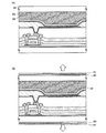
以上のように作製した表示装置の構成の1例を図7参照しながら説明する。なお、形が異なっていても同様の機能を示す部分には同じ符号を付し、その説明を省略する部分もある。本実施の形態では、LDD構造を有する薄膜トランジスタ70が接続部61aを介して発光素子93に接続している。
One example of the structure of the display device manufactured as described above will be described with reference to FIG. In addition, even if the shapes are different, parts showing similar functions are denoted by the same reference numerals, and explanations thereof are omitted. In this embodiment mode, the
図7(A)は陽極101が透光性を有する導電膜により形成されており、基板50側に発光積層体66より発せられた光が取り出される構造である。なお94は対向基板であり、発光素子93が形成された後、シール材などを用い、基板50に固着される。対向基板94と素子との間に透光性を有する樹脂88等を充填し、封止することによって発光素子93が水分により劣化することを防ぐ事ができる。また、樹脂88が吸湿性を有していることが望ましい。さらに樹脂88中に透光性の高い乾燥剤89を分散させるとさらに水分の影響を抑えることが可能になるためさらに望ましい形態である。
7A illustrates a structure in which the
図7(B)は陽極101と陰極106両方が透光性を有する導電膜により形成されており、基板50及び対向基板94の両方に光を取り出すことが可能な構成となっている。また、この構成では基板50と対向基板94の外側に偏光板90を設けることによって画面が透けてしまうことを防ぐことができ、視認性が向上する。偏光板90の外側には保護フィルム91を設けると良い。
In FIG. 7B, both the
なお、表示機能を有する本発明の表示装置には、アナログのビデオ信号、デジタルのビデオ信号のどちらを用いてもよい。デジタルのビデオ信号を用いる場合はそのビデオ信号が電圧を用いているものと、電流を用いているものとに分けられる。発光素子の発光時において、画素に入力されるビデオ信号は、定電圧のものと、定電流のものがあり、ビデオ信号が定電圧のものには、発光素子に印加される電圧が一定のものと、発光素子に流れる電流が一定のものとがある。またビデオ信号が定電流のものには、発光素子に印加される電圧が一定のものと、発光素子に流れる電流が一定のものとがある。この発光素子に印加される電圧が一定のものは定電圧駆動であり、発光素子に流れる電流が一定のものは定電流駆動である。定電流駆動は、発光素子の抵抗変化によらず、一定の電流が流れる。本発明の発光表示装置及びその駆動方法は、上記したいずれの方法を用いても良い。 Note that either an analog video signal or a digital video signal may be used for the display device of the present invention having a display function. When a digital video signal is used, the video signal is classified into one using a voltage and one using a current. When the light emitting element emits light, the video signal input to the pixel has a constant voltage and a constant current. When the video signal has a constant voltage, the voltage applied to the light emitting element is constant. And the current flowing through the light emitting element is constant. In addition, a video signal having a constant current includes a constant voltage applied to the light emitting element and a constant current flowing in the light emitting element. A constant voltage applied to the light emitting element is constant voltage driving, and a constant current flowing through the light emitting element is constant current driving. In constant current driving, a constant current flows regardless of the resistance change of the light emitting element. Any of the above-described methods may be used for the light emitting display device and the driving method thereof of the present invention.
本実施の形態のような方法で形成された本発明の表示装置は駆動電圧が小さく、駆動電圧の経時上昇も小さい表示装置である。 The display device of the present invention which is formed by the method of this embodiment mode is a display device which has a low driving voltage and a small increase in the driving voltage with time.
(実施の形態4)
本実施の形態では、本発明の一形態に相当する発光装置のパネルの外観について図8を用いて説明する。図8(A)は基板上に形成されたトランジスタおよび発光素子を基板と対向基板4006との間に形成したシール材によって封止したパネルの上面図であり、図8(B)は図8(A)の断面図に相応する。また、このパネルに搭載されている発光素子の有する構造は、電極に接する層が正孔を発生する層であり、発光層が正孔を発生する層で挟まれた構造となっている。さらに、発光素子における陰極側の正孔を発生する層と発光層との間には電子を発生する層が設けられている。
(Embodiment 4)
In this embodiment, the appearance of a panel of a light-emitting device that corresponds to one embodiment of the present invention will be described with reference to FIGS. FIG. 8A is a top view of a panel in which a transistor and a light-emitting element formed over a substrate are sealed with a sealant formed between the substrate and a
基板4001上に設けられた画素部4002と信号線駆動回路4003と走査線駆動回路4004とを囲むようにして、シール材4005が設けられている。また、画素部4002と信号線駆動回路4003と、走査線駆動回路4004の上に対向基板4006が設けられている。よって画素部4002と信号線駆動回路4003と、走査線駆動回路4004とは基板4001とシール材4005と対向基板4006とによって充填材4007と共に密封されている。
A
また、基板4001上に設けられた画素部4002と信号線駆動回路4003と走査線駆動回路4004とは薄膜トランジスタを複数有しており、図8(B)では信号線駆動回路4003に含まれる薄膜トランジスタ4008と、画素部4002に含まれる薄膜トランジスタ4010とを示す。
The
また、発光素子4011は、薄膜トランジスタ4010と電気的に接続されている。
The
また、引き回し配線4014は画素部4002と信号線駆動回路4003と、走査線駆動回路4004とに、信号、または電源電圧を層供給する為の配線に相当する。引き回し配線4014は、引き回し配線4015a及び引き回し配線4015bを介して接続端子4016と接続されている。接続端子4016はフレキシブルプリントサーキット(FPC)4018が有する端子と異方性導電膜4019を介して電気的に接続されている。
The lead wiring 4014 corresponds to a wiring for supplying a signal or a power supply voltage to the
なお、充填材4007としては窒素やアルゴンなどの不活性な気体の他に、紫外線硬化樹脂または熱硬化樹脂を用いることができ、ポリビニルクロライド、アクリル、ポリイミド、エポキシ樹脂、シリコン樹脂、ポリビニルブチラル、またはエチレンビニレンアセテートを用いる事ができる。
Note that as the
なお、本発明の表示装置は発光素子を有する画素部が形成されたパネルと、該パネルにICが実装されたモジュールとをその範疇に含む。 Note that the display device of the present invention includes in its category a panel in which a pixel portion having a light-emitting element is formed and a module in which an IC is mounted on the panel.
本実施の形態のような構成のパネル及びモジュールは、駆動電圧が小さく、駆動電圧の経時上昇も小さいパネル及びモジュールである。 The panel and module configured as in the present embodiment are panels and modules that have a small driving voltage and a small increase in the driving voltage with time.
(実施の形態5)
実施の形態4にその一例を示したようなモジュールを搭載した本発明の電子機器として、ビデオカメラ、デジタルカメラ、ゴーグル型ディスプレイ(ヘッドマウントディスプレイ)、ナビゲーションシステム、音響再生装置(カーオーディオコンポ等)、コンピュータ、ゲーム機器、携帯情報端末(モバイルコンピュータ、携帯電話、携帯型ゲーム機または電子書籍等)、記録媒体を備えた画像再生装置(具体的にはDigital Versatile Disc(DVD)等の記録媒体を再生し、その画像を表示しうるディスプレイを備えた装置)などが挙げられる。それらの電子機器の具体例を図9に示す。
(Embodiment 5)
As an electronic device of the present invention on which a module whose example is shown in
図9(A)は発光表示装置でありテレビ受像器やパーソナルコンピュータのモニターなどがこれに当たる。筐体2001、表示部2003、スピーカー部2004等を含む。本発明の発光表示装置は表示部2003の駆動電圧が小さく、駆動電圧の経時上昇も小さい発光表示装置である。画素部にはコントランスを高めるため、偏光板、又は円偏光板を備えるとよい。例えば、封止基板へ1/4λ板、1/2λ板、偏光板の順にフィルムを設けるとよい。さらに偏光板上に反射防止膜を設けてもよい。 FIG. 9A illustrates a light-emitting display device, such as a television receiver or a personal computer monitor. A housing 2001, a display portion 2003, a speaker portion 2004, and the like are included. The light-emitting display device of the present invention is a light-emitting display device in which the driving voltage of the display portion 2003 is small and the increase in driving voltage with time is small. In order to increase the contrast in the pixel portion, a polarizing plate or a circular polarizing plate may be provided. For example, a film may be provided on the sealing substrate in the order of a 1 / 4λ plate, a 1 / 2λ plate, and a polarizing plate. Further, an antireflection film may be provided on the polarizing plate.
図9(B)は携帯電話であり、本体2101、筐体2102、表示部2103、音声入力部2104、音声出力部2105、操作キー2106、アンテナ2108等を含む。本発明の携帯電話は表示部2103の駆動電圧が小さく、駆動電圧の経時上昇も小さい携帯電話である。 FIG. 9B illustrates a mobile phone, which includes a main body 2101, a housing 2102, a display portion 2103, an audio input portion 2104, an audio output portion 2105, operation keys 2106, an antenna 2108, and the like. The cellular phone of the present invention is a cellular phone in which the drive voltage of the display portion 2103 is small and the increase in drive voltage with time is small.
図9(C)はコンピュータであり、本体2201、筐体2202、表示部2203、キーボード2204、外部接続ポート2205、ポインティングマウス2206等を含む。本発明のコンピュータは表示部2203の駆動電圧が小さく、駆動電圧の経時上昇も小さいコンピュータである。図9(C)ではノート型のコンピュータを例示したが、ハードディスクと表示部が一体化したデスクトップ型のコンピュータなどにも適用することが可能である。 FIG. 9C illustrates a computer, which includes a main body 2201, a housing 2202, a display portion 2203, a keyboard 2204, an external connection port 2205, a pointing mouse 2206, and the like. The computer of the present invention is a computer in which the drive voltage of the display portion 2203 is small and the drive voltage rises with time. Although a notebook computer is illustrated in FIG. 9C, the present invention can also be applied to a desktop computer in which a hard disk and a display portion are integrated.
図9(D)はモバイルコンピュータであり、本体2301、表示部2302、スイッチ2303、操作キー2304、赤外線ポート2305等を含む。本発明のモバイルコンピュータは表示部2302の駆動電圧が小さく、駆動電圧の経時上昇も小さいモバイルコンピュータである。 FIG. 9D illustrates a mobile computer, which includes a main body 2301, a display portion 2302, a switch 2303, operation keys 2304, an infrared port 2305, and the like. The mobile computer of the present invention is a mobile computer in which the driving voltage of the display portion 2302 is small and the increase in driving voltage with time is small.
図9(E)は携帯型のゲーム機であり、筐体2401、表示部2402、スピーカー部2403、操作キー2404、記録媒体挿入部2405等を含む。本発明の携帯型ゲーム機は表示部2402の駆動電圧が小さく、駆動電圧の経時上昇も小さい携帯型ゲーム機である。 FIG. 9E illustrates a portable game machine including a housing 2401, a display portion 2402, speaker portions 2403, operation keys 2404, a recording medium insertion portion 2405, and the like. The portable game machine of the present invention is a portable game machine in which the drive voltage of the display portion 2402 is small and the drive voltage rises with time.
以上の様に、本発明の適用範囲は極めて広く、あらゆる分野の電子機器に用いることが可能である。
(実施の形態6)
As described above, the applicable range of the present invention is so wide that it can be used for electronic devices in various fields.
(Embodiment 6)
図10には下面発光、両面発光、上面発光の例を示した。実施の形態2に作成工程を記載した構造は図10(C)の構造に相当する。図10(A)、(B)は図10(C)における第1の層間絶縁層900を自己平坦性を有する材料で形成し、薄膜トランジスタ901に接続する配線と発光素子の陽極101を同じ層間絶縁層上に形成した場合の構成である。図10(A)は発光素子の陽極101のみを透光性を有する材料で形成し、発光装置の下部に向かって光が射出する下面発光の構成、図10(B)はITOやITSO、IZOなど透光性を有する材料を陰極106として形成することで図10(B)のように両面より光を取り出すことのできる両面発光の発光表示装置を得ることが可能となる。なお、アルミニウムや銀など厚膜で形成すると非透光性であるが、薄膜化すると透光性を有するようになるため、アルミニウムや銀の透光性を有する程度の薄膜で陰極106を形成しても両面発光とすることができる。
FIG. 10 shows an example of bottom emission, double side emission, and top emission. The structure in which the creation process is described in
(実施の形態7) (Embodiment 7)
本実施の形態では、実施の形態4で示したパネル、モジュールが有する画素回路、保護回路及びそれらの動作について説明する。なお、図5、図6に示してきた断面図は駆動用TFT1403と発光素子1405の断面図となっている。
In this embodiment, pixel circuits and protection circuits included in the panel and module described in
図11(A)に示す画素は、列方向に信号線1410及び電源線1411、1412、行方向に走査線1414が配置される。また、スイッチング用TFT1401、駆動用TFT1403、電流制御用TFT1404、容量素子1402及び発光素子1405を有する。
In the pixel shown in FIG. 11A, a
図11(C)に示す画素は、駆動用TFT1403のゲート電極が、行方向に配置された電源線1412に接続される点が異なっており、それ以外は図11(A)に示す画素と同じ構成である。つまり、図11(A)(C)に示す両画素は、同じ等価回路図を示す。しかしながら、列方向に電源線1412が配置される場合(図11(A))と、行方向に電源線1412が配置される場合(図11(C))とでは、各電源線は異なるレイヤーの導電膜で形成される。ここでは、駆動用TFT1403のゲート電極が接続される配線に注目し、これらを作製するレイヤーが異なることを表すために、図11(A)(C)として分けて記載する。
The pixel shown in FIG. 11C is different from the pixel shown in FIG. 11A in that the gate electrode of the driving
図11(A)(C)に示す画素の特徴として、画素内に駆動用TFT1403と電流制御用TFT1404が直列に接続されており、駆動用TFT1403のチャネル長L(1403)、チャネル幅W(1403)、電流制御用TFT1404のチャネル長L(1404)、チャネル幅W(1404)は、L(1403)/W(1403):L(1404)/W(1404)=5〜6000:1を満たすように設定するとよい。
As a feature of the pixel shown in FIGS. 11A and 11C, a driving
なお、駆動用TFT1403は、飽和領域で動作し発光素子1405に流れる電流値を制御する役目を有し、電流制御用TFT1404は線形領域で動作し発光素子1405に対する電流の供給を制御する役目を有する。両TFTは同じ導電型を有していると作製工程上好ましく、本実施の形態ではnチャネル型TFTとして形成する。また駆動用TFT1403には、エンハンスメント型だけでなく、ディプリーション型のTFTを用いてもよい。上記構成を有する本発明は、電流制御用TFT1404が線形領域で動作するために、電流制御用TFT1404のVgsの僅かな変動は、発光素子1405の電流値に影響を及ぼさない。つまり、発光素子1405の電流値は、飽和領域で動作する駆動用TFT1403により決定することができる。上記構成により、TFTの特性バラツキに起因した発光素子の輝度ムラを改善して、画質を向上させた表示装置を提供することができる。
Note that the driving
図11(A)〜(D)に示す画素において、スイッチング用TFT1401は、画素に対するビデオ信号の入力を制御するものであり、スイッチング用TFT1401がオンとなると、画素内にビデオ信号が入力される。すると、容量素子1402にそのビデオ信号の電圧が保持される。なお図11(A)(C)には、容量素子1402を設けた構成を示したが、本発明はこれに限定されず、ビデオ信号を保持する容量がゲート容量などでまかなうことが可能な場合には、容量素子1402を設けなくてもよい。
In the pixels shown in FIGS. 11A to 11D, the switching
図11(B)に示す画素は、TFT1406と走査線1414を追加している以外は、図11(A)に示す画素構成と同じである。同様に、図11(D)に示す画素は、TFT1406と走査線1414を追加している以外は、図11(C)に示す画素構成と同じである。
The pixel shown in FIG. 11B has the same pixel structure as that shown in FIG. 11A except that a
TFT1406は、新たに配置された走査線1414によりオン又はオフが制御される。TFT1406がオンとなると、容量素子1402に保持された電荷は放電し、電流制御用TFT1404がオフとなる。つまり、TFT1406の配置により、強制的に発光素子1405に電流が流れない状態を作ることができる。そのためTFT1406を消去用TFTと呼ぶことができる。従って、図11(B)(D)の構成は、全ての画素に対する信号の書き込みを待つことなく、書き込み期間の開始と同時又は直後に点灯期間を開始することができるため、デューティ比を向上することが可能となる。
The
図11(E)に示す画素は、列方向に信号線1410、電源線1411、行方向に走査線1414が配置される。また、スイッチング用TFT1401、駆動用TFT1403、容量素子1402及び発光素子1405を有する。図11(F)に示す画素は、TFT1406と走査線1415を追加している以外は、図7(E)に示す画素構成と同じである。なお、図11(F)の構成も、TFT1406の配置により、デューティ比を向上することが可能となる。
In the pixel shown in FIG. 11E, a
以上のように、多様な画素回路を採用することができる。特に、非晶質半導体膜から薄膜トランジスタを形成する場合、駆動用TFT1403の半導体膜を大きくすると好ましい。そのため、上記画素回路において、電界発光層からの光が封止基板側から射出する上面発光型とすると好ましい。
As described above, various pixel circuits can be employed. In particular, in the case where a thin film transistor is formed from an amorphous semiconductor film, it is preferable to increase the semiconductor film of the driving
このようなアクティブマトリクス型の発光装置は、画素密度が増えた場合、各画素にTFTが設けられているため低電圧駆動でき、有利であると考えられている。 Such an active matrix light-emitting device is considered to be advantageous because it can be driven at a low voltage because a TFT is provided in each pixel when the pixel density is increased.
本実施の形態では、一画素に各TFTが設けられるアクティブマトリクス型の発光装置について説明したが、一列毎にTFTが設けられるパッシブマトリクス型の発光装置を形成することもできる。パッシブマトリクス型の発光装置は、各画素にTFTが設けられていないため、高開口率となる。発光が電界発光層の両側へ射出する発光装置の場合、パッシブマトリクス型の表示装置を用いる透過率が高まる。 In this embodiment mode, an active matrix light-emitting device in which each pixel is provided with each TFT has been described; however, a passive matrix light-emitting device in which a TFT is provided for each column can also be formed. A passive matrix light-emitting device has a high aperture ratio because a TFT is not provided for each pixel. In the case of a light-emitting device in which light emission is emitted to both sides of an electroluminescent layer, transmittance using a passive matrix display device is increased.
これらのような画素回路をさらに有する本発明の表示装置は、駆動電圧が小さく、駆動電圧の経時上昇も小さい上、各々の特徴を有する表示装置とすることができる。 The display device of the present invention further including such a pixel circuit can have a small driving voltage, a small increase in the driving voltage with time, and a display device having each characteristic.
続いて、図11(E)に示す等価回路を用い、走査線及び信号線に保護回路としてダイオードを設ける場合について説明する。 Next, a case where a diode is provided as a protective circuit in the scan line and the signal line is described using the equivalent circuit illustrated in FIG.
図12には、画素部1500にスイッチング用TFT1401、1403、容量素子1402、発光素子1405が設けられている。信号線1410には、ダイオード1561と1562が設けられている。ダイオード1561と1562は、スイッチング用TFT1401又は1403と同様に、上記実施の形態に基づき作製され、ゲート電極、半導体層、ソース電極及びドレイン電極等を有する。ダイオード1561と1562は、ゲート電極と、ドレイン電極又はソース電極とを接続することによりダイオードとして動作させている。
In FIG. 12, switching
ダイオードと接続する共通電位線1554、1555はゲート電極と同じレイヤーで形成している。従って、ダイオードのソース電極又はドレイン電極と接続するには、ゲート絶縁層にコンタクトホールを形成する必要がある。
Common
走査線1414に設けられるダイオードも同様な構成である。
A diode provided in the
このように、本発明によれば、入力段に設けられる保護ダイオードを同時に形成することができる。なお、保護ダイオードを形成する位置は、これに限定されず、駆動回路と画素との間に設けることもできる。 Thus, according to the present invention, the protection diode provided in the input stage can be formed simultaneously. Note that the position where the protective diode is formed is not limited to this, and the protective diode can be provided between the driver circuit and the pixel.
このような保護回路を有する本発明の表示装置は、駆動電圧の経時上昇も小さい上、表示装置としての信頼性も高めることが可能となる。 In the display device of the present invention having such a protection circuit, a rise in drive voltage with time is small, and reliability as a display device can be improved.
本実施例では本発明の発光素子の測定データを示す。 In this example, measurement data of the light-emitting element of the present invention is shown.
まず、本実施例における発光素子の作製方法について説明する。本実施例における発光素子は実施の形態1に示した発光素子の構造に準拠する。本実施例では絶縁物100としてガラス基板を使用した。当該ガラス基板上にケイ素を含有するITOをスパッタリング法により成膜し、陽極101を形成した。陽極101の膜厚は110nmとなるように成膜した。
First, a method for manufacturing a light-emitting element in this example is described. The light-emitting element in this example conforms to the structure of the light-emitting element described in
続いて、陽極101の上にモリブデン酸化物とα−NPDを共蒸着することによって、モリブデン酸化物とα−NPDよりなる第1の正孔を発生する層102を形成した。ここで第1の正孔を発生する層102の膜厚は50nmとなるようにした。
Subsequently, molybdenum oxide and α-NPD were co-evaporated on the
次に第1の正孔を発生する層102の上に発光層104を形成した。発光層104は3層構造とし、第1の正孔を発生する層102側から正孔輸送層、発光物質が分散された層、電子輸送層の順で形成した。正孔輸送層は、α−NPDを真空蒸着法により膜厚10nmとなるように形成し、発光物質が分散された層はAlq3とクマリン6を共蒸着法により成膜することでAlq3とクマリン6を含む層を膜厚35nmとなるように形成し、電子輸送層はAlq3のみを真空蒸着法により膜厚10nmとなるように形成した。尚、発光物質が分散された層はAlq3とクマリン6の割合が、質量比で1:0.005となるように調節した。
Next, the light-emitting
続いて、発光層104上にAlq3とリチウムとを共蒸着することによって、Alq3とリチウムとよりなる電子を発生する層105を膜厚10nmとなるように形成した。なお、Alq3とリチウムとの質量比は1:0.01となるように調節した。
Subsequently, Alq 3 and lithium were co-evaporated on the light-emitting
次に、電子を発生する層105上に、モリブデン酸化物とα−NPDを共蒸着することによって、モリブデン酸化物とα−NPDよりなる第2の正孔を発生する層103を形成した。ここで第1の正孔を発生する層102の膜厚は20nmとなるようにした。また、α−NPDとモリブデン酸化物のモル比は1:1となるようにした。
Next, a
第2の正孔を発生する層105上にはアルミニウムによる陰極106を形成した。膜厚は100nmとした。
A
記構成を有する本発明の発光素子は、電圧をかけると、第2の正孔を発生する層103より第2の電極に正孔が注入される。また、電子を発生する層105より電子が発光層104に注入される。さらに、第1の正孔を発生する層102より発光層104に正孔が注入され、発光層において注入された電子と正孔が再結合し、クマリン6から発光が得られる。
When a voltage is applied to the light-emitting element of the present invention having the above structure, holes are injected into the second electrode from the
このように作製した本実施例の発光素子の電圧−輝度特性を図13に、電圧−電流特性を図14に示す。図13おいて横軸は電圧(V)、縦軸は輝度(cd/m2)を表す。また、図14において横軸は電圧(V)、縦軸は電流(mA)を表す。 FIG. 13 shows voltage-luminance characteristics and FIG. 14 shows voltage-current characteristics of the light-emitting element manufactured in this manner. In FIG. 13, the horizontal axis represents voltage (V), and the vertical axis represents luminance (cd / m 2 ). In FIG. 14, the horizontal axis represents voltage (V) and the vertical axis represents current (mA).
このように、本実施例における発光素子は、良好な特性を示す。 As described above, the light-emitting element in this example exhibits favorable characteristics.
なお、本実施例において正孔を発生する層として用いたα―NPDとモリブデン酸化物よりなる複合材料の吸収スペクトルを図22(A)に示す。なお、図22(B)はα―NPDのみの吸収スペクトル、図22(C)はモリブデン酸化物のみの吸収スペクトルである。図から分かるように、α―NPDとモリブデン酸化物よりなる複合材料の吸収スペクトルには、α―NPDのみ、及びモリブデン酸化物のみでは現れないピークが現れていることが分かる。これはα―NPDとモリブデン酸化物が相互作用することによって正孔が発生していることを示すものと考えられる。 Note that FIG. 22A shows an absorption spectrum of a composite material of α-NPD and molybdenum oxide which is used as a layer for generating holes in this example. Note that FIG. 22B shows an absorption spectrum of only α-NPD, and FIG. 22C shows an absorption spectrum of only molybdenum oxide. As can be seen from the figure, the absorption spectrum of the composite material composed of α-NPD and molybdenum oxide shows peaks that do not appear only with α-NPD and with molybdenum oxide alone. This is considered to indicate that holes are generated by the interaction between α-NPD and molybdenum oxide.
本実施例では、正孔を発生する層において、正孔輸送性物質と、その物質に対し電子受容性を示す物質との混合割合が異なる四つの発光素子、発光素子(1)、発光素子(2)、発光素子(3)、発光素子(4)の作製方法と、それらの素子の特性について説明する。 In this embodiment, four light-emitting elements, a light-emitting element (1), and a light-emitting element (where the mixing ratio of a hole-transporting substance and a substance that exhibits electron accepting property to the substance in the layer that generates holes are different. 2) A method for manufacturing the light-emitting element (3) and the light-emitting element (4), and characteristics of these elements will be described.
まず、本実施例における発光素子の作製方法について説明する。本実施例における発光素子は実施の形態1に示した発光素子の構造に準拠する。本実施例では絶縁物100としてガラス基板を使用した。当該ガラス基板上にケイ素を含有するITOをスパッタリング法により成膜し、陽極101を形成した。陽極101の膜厚は110nmとなるように成膜した。
First, a method for manufacturing a light-emitting element in this example is described. The light-emitting element in this example conforms to the structure of the light-emitting element described in
続いて、陽極101の上にモリブデン酸化膜を真空蒸着法によって成膜し、モリブデン酸化膜からなる第1の正孔を発生する層102を形成した。ここで膜厚は5nmとなるようにした。
Subsequently, a molybdenum oxide film was formed on the
次に第1の正孔を発生する層102の上に発光層104を形成した。発光層104は3層構造とし、第1の正孔を発生する層102側から正孔輸送層、発光物質が分散された層、電子輸送層の順で形成した。正孔輸送層は、α−NPDを真空蒸着法により膜厚55nmとなるように形成し、発光物質が分散された層はAlq3とクマリン6を共蒸着法により成膜することでAlq3とクマリン6を含む層を膜厚35nmとなるように形成し、電子輸送層はAlq3のみを真空蒸着法により膜厚10nmとなるように形成した。尚、発光物質が分散された層はAlq3とクマリン6の割合が、質量比で1:0.005となるように調節した。
Next, the light-emitting
続いて、発光層104上にAlq3とリチウムとを共蒸着することによって、Alq3とリチウムとよりなる電子を発生する層105を膜厚10nmとなるように形成した。なお、Alq3とリチウムとの質量比は1:0.01となるように調節した。
Subsequently, Alq 3 and lithium were co-evaporated on the light-emitting
次に、電子を発生する層105上に、モリブデン酸化物とα−NPDを共蒸着することによって、モリブデン酸化物とα−NPDよりなる第2の正孔を発生する層103を形成した。ここで、発光素子(1)については、α−NPDとモリブデン酸化物とのモル比は0.5(=α−NPD/モリブデン酸化物)となるように調節した。また、発光素子(2)については、α−NPDとモリブデン酸化物とのモル比は1.0(=α−NPD/モリブデン酸化物)となるように調節した。また、発光素子(3)については、α−NPDとモリブデン酸化物とのモル比は1.5(=α−NPD/モリブデン酸化物)となるように調節した。また、発光素子(4)については、α−NPDとモリブデン酸化物とのモル比は2.0(=α−NPD/モリブデン酸化物)となるように調節した。また、第2の正孔を発生する層102の膜厚は20nmとなるようにした。
Next, a
第2の正孔を発生する層103上にはアルミニウムによる陰極106を形成した。膜厚は100nmとした。
A
記構成を有する本発明の発光素子は、電圧をかけると、第2の正孔を発生する層103より第2の電極に正孔が注入される。また、電子を発生する層105より電子が発光層104に注入される。さらに、第1の正孔を発生する層102より発光層104に正孔が注入され、発光層において注入された電子と正孔が再結合し、クマリン6から発光が得られる。
When a voltage is applied to the light-emitting element of the present invention having the above structure, holes are injected into the second electrode from the
本実施例の発光素子の電圧−輝度特性を図15に、電流密度−輝度特性を図16に、電圧−電流特性を図17に示す。図15において、横軸は電圧(V)、縦軸は輝度(cd/m2)を表す。また、図16において、横軸は電流密度(mA/cm2)、縦軸は輝度(cd/m2)を表す。また、図17において、横軸は電圧(V)、縦軸は電流(mA)を表す。図15〜図17において、▲印は発光素子(1)、●印は発光素子(2)、○印は発光素子(3)、■印は発光素子(4)の特性を表す。 FIG. 15 shows the voltage-luminance characteristics of the light emitting element of this example, FIG. 16 shows the current density-luminance characteristics, and FIG. 17 shows the voltage-current characteristics. In FIG. 15, the horizontal axis represents voltage (V) and the vertical axis represents luminance (cd / m 2 ). In FIG. 16, the horizontal axis represents current density (mA / cm 2 ) and the vertical axis represents luminance (cd / m 2 ). In FIG. 17, the horizontal axis represents voltage (V), and the vertical axis represents current (mA). 15 to 17, the ▲ mark indicates the characteristics of the light emitting element (1), the ● mark indicates the characteristics of the light emitting element (2), the ◯ mark indicates the characteristics of the light emitting element (3), and the ■ mark indicates the characteristics of the light emitting element (4).
図15〜図17、から、いずれの発光素子についても、良好に動作していることが分かる。また、特に、正孔を発生する層におけるα−NPDとモリブデン酸化物とのモル比(=α−NPD/モリブデン酸化物)が1〜2である発光素子(2)〜(4)では、任意の電圧を印加したときに得られる輝度が高く、また電流値も大きいことが分かる。このように、α−NPDとモリブデン酸化物とのモル比(=α−NPD/モリブデン酸化物)が1〜2になるように調節することで、低い駆動電圧で動作する発光素子を得られる。 15 to 17, it can be seen that any of the light-emitting elements operates well. In particular, in the light-emitting elements (2) to (4) in which the molar ratio of α-NPD to molybdenum oxide (= α-NPD / molybdenum oxide) in the hole-generating layer is 1 to 2, it is optional. It can be seen that the luminance obtained when the above voltage is applied is high and the current value is also large. Thus, by adjusting the molar ratio of α-NPD to molybdenum oxide (= α-NPD / molybdenum oxide) to be 1 to 2, a light-emitting element that operates at a low driving voltage can be obtained.
次に、本実施例の発光素子について、連続点灯試験を行った結果について説明する。連続点灯試験は、上記のようにして作製した発光素子を、窒素雰囲気で封止した後、常温下で、次のようにして行った。 Next, the results of performing a continuous lighting test on the light-emitting element of this example will be described. The continuous lighting test was performed as follows at normal temperature after sealing the light-emitting element manufactured as described above in a nitrogen atmosphere.
図16からも分かるように、初期状態の本発明の発光素子において、3000cd/m2の輝度で発光するために必要な電流密度は26.75mA/cm2である。本実施例では、26.75mA/cm2の電流を一定時間を流し続け、26.75mA/cm2の電流を流すのに必要な電圧の経時変化、並びに輝度の経時変化について調べた。測定結果を図18、図19に示す。図18において、横軸は経過した時間(hour)、縦軸は26.75mA/cm2の電流を流すのに必要な電圧(V)を表す。また、図19において、横軸は経過した時間(hour)、縦軸は輝度(任意単位)を表す。なお、輝度(任意単位)は、初期状態の輝度を100として表した、初期輝度に対する相対値(任意時間における輝度を初期輝度で割り、さらに100倍して求めた値。)である。 As can be seen from FIG. 16, in the light-emitting element of the present invention in the initial state, the current density required to emit light with a luminance of 3000 cd / m 2 is 26.75 mA / cm 2 . In this example, the current of 26.75 mA / cm 2 was kept flowing for a certain period of time, and the change with time of the voltage necessary to pass the current of 26.75 mA / cm 2 and the change with time of the luminance were examined. The measurement results are shown in FIGS. In FIG. 18, the horizontal axis represents the elapsed time (hour), and the vertical axis represents the voltage (V) necessary to pass a current of 26.75 mA / cm 2 . In FIG. 19, the horizontal axis represents elapsed time (hour), and the vertical axis represents luminance (arbitrary unit). Note that the luminance (arbitrary unit) is a relative value with respect to the initial luminance (value obtained by dividing the luminance at an arbitrary time by the initial luminance and multiplying by 100) with the initial luminance as 100.
図18より、いずれの発光素子においても26.75mA/cm2の電流密度の電流を流すのに必要な電圧は、100時間経過後において、初期状態よりも約1Vしか高くなっていないことが分かる。このことから、本発明の発光素子が、経時変化に伴った電圧の上昇の少ない良好な素子であることが分かる。 From FIG. 18, it can be seen that the voltage required to pass a current with a current density of 26.75 mA / cm 2 is only about 1 V higher than the initial state after 100 hours. . From this, it can be seen that the light-emitting element of the present invention is a good element with little increase in voltage with time.
なお、実施例1および実施例2のいずれの発光素子についても、発光層として機能する層の他、正孔注入層、正孔輸送層、電子輸送層等として機能する層を形成しているが、必ずしもこれらの層を設けなくてもよい。また、実施例1、実施例2では、共に、発光層として機能する層を形成した後、電子を発生する層を形成し、さらにその後正孔を発生する層を形成しているが、本発明の発光素子の作製方法はこれに限定されるものではない。例えば、正孔を発生する層を形成した後、電子を発生する層を形成し、さらにその後発光層として機能する層を含む層を形成しても構わない。 In each of the light-emitting elements of Example 1 and Example 2, a layer that functions as a hole injection layer, a hole transport layer, an electron transport layer, or the like is formed in addition to a layer that functions as a light-emitting layer. However, these layers are not necessarily provided. Further, in both Example 1 and Example 2, after forming a layer that functions as a light emitting layer, a layer that generates electrons is formed, and then a layer that generates holes is formed. However, the manufacturing method of the light emitting element is not limited to this. For example, after forming a hole generating layer, an electron generating layer may be formed, and then a layer including a layer functioning as a light emitting layer may be formed.
本実施例では実施例1とは異なる材料を用いた本発明の発光素子の測定データを示す。 In this example, measurement data of a light-emitting element of the present invention using a material different from that in Example 1 is shown.
まず、本実施例における発光素子の作製方法について説明する。本実施例における発光素子は実施の形態1に示した発光素子の構造に準拠する。本実施例では絶縁物100としてガラス基板を使用した。当該ガラス基板上にケイ素を含有するITOをスパッタリング法により成膜し、陽極101を形成した。陽極101の膜厚は110nmとなるように成膜した。
First, a method for manufacturing a light-emitting element in this example is described. The light-emitting element in this example conforms to the structure of the light-emitting element described in
続いて、陽極101の上にモリブデン酸化物とDNTPDを共蒸着することによって、モリブデン酸化物とDNTPDよりなる第1の正孔を発生する層102を形成した。ここで第1の正孔を発生する層102の膜厚は50nmとなるようにした。DNTPDとモリブデン酸化物の質量比は4:2となるように蒸着した。
Subsequently, molybdenum oxide and DNTPD were co-evaporated on the
次に第1の正孔を発生する層102の上に発光層104を形成した。発光層104は3層構造とし、第1の正孔を発生する層102側から正孔輸送層、発光物質が分散された層、電子輸送層の順で形成した。正孔輸送層は、α−NPDを真空蒸着法により膜厚10nmとなるように形成し、発光物質が分散された層はAlq3とクマリン6を共蒸着法により成膜することでAlq3とクマリン6を含む層を膜厚35nmとなるように形成し、電子輸送層はAlq3のみを真空蒸着法により膜厚10nmとなるように形成した。尚、発光物質が分散された層はAlq3とクマリン6の割合が、質量比で1:0.005となるように調節した。
Next, the light-emitting
続いて、発光層104上にAlq3とリチウムとを共蒸着することによって、Alq3とリチウムとよりなる電子を発生する層105を膜厚10nmとなるように形成した。なお、Alq3とリチウムとの質量比は1:0.01となるように調節した。
Subsequently, Alq 3 and lithium were co-evaporated on the light-emitting
次に、電子を発生する層105上に、モリブデン酸化物とDNTPDを共蒸着することによって、モリブデン酸化物とDNTPDよりなる第2の正孔を発生する層103を形成した。ここで第1の正孔を発生する層102の膜厚は20nmとなるようにした。また、DNTPDとモリブデン酸化物の質量比は4:2となるようにした。
Next, a
第2の正孔を発生する層103上にはアルミニウムによる陰極106を形成した。膜厚は100nmとした。
A
記構成を有する本発明の発光素子は、電圧をかけると、第2の正孔を発生する層103より第2の電極に正孔が注入される。また、電子を発生する層105より電子が発光層104に注入される。さらに、第1の正孔を発生する層102より発光層104に正孔が注入され、発光層において注入された電子と正孔が再結合し、クマリン6から発光が得られる。
When a voltage is applied to the light-emitting element of the present invention having the above structure, holes are injected into the second electrode from the
このように作製した本実施例の発光素子の電圧−輝度特性を図20に、電圧−電流特性を図21に示す。図20おいて横軸は電圧(V)、縦軸は輝度(cd/m2)を表す。また、図21において横軸は電圧(V)、縦軸は電流(mA)を表す。 FIG. 20 shows the voltage-luminance characteristics and FIG. 21 shows the voltage-current characteristics of the light-emitting element manufactured in this way. In FIG. 20, the horizontal axis represents voltage (V), and the vertical axis represents luminance (cd / m 2 ). In FIG. 21, the horizontal axis represents voltage (V) and the vertical axis represents current (mA).
このように、本実施例における発光素子は、良好な特性を示す。 As described above, the light-emitting element in this example exhibits favorable characteristics.
なお、本実施例において正孔を発生する層として用いたDNTPDとモリブデン酸化物よりなる複合材料の吸収スペクトルを図23(A)に示す。なお、図23(B)はDNTPDのみの吸収スペクトル、図23(C)はモリブデン酸化物のみの吸収スペクトルである。図から分かるように、DNTPDとモリブデン酸化物よりなる複合材料の吸収スペクトルには、DNTPDのみ、及びモリブデン酸化物のみでは現れないピークが現れていることが分かる。これはDNTPDとモリブデン酸化物が相互作用することによって正孔が発生していることを示すものと考えられる。 Note that FIG. 23A illustrates an absorption spectrum of a composite material including DNTPD and molybdenum oxide which is used as a layer for generating holes in this example. Note that FIG. 23B shows an absorption spectrum of only DNTPD, and FIG. 23C shows an absorption spectrum of only molybdenum oxide. As can be seen from the figure, in the absorption spectrum of the composite material composed of DNTPD and molybdenum oxide, it can be seen that peaks that do not appear only with DNTPD and with molybdenum oxide appear. This is considered to indicate that holes are generated by the interaction between DNTPD and molybdenum oxide.
本実施例では、正孔を発生する層の膜厚を変化させることによって、発光の視野角依存性や発光スペクトルを制御する、いわゆる発光素子の光学設計について図24、図25を参照しながら説明する。
In this embodiment, the optical design of a so-called light emitting element that controls the viewing angle dependency of light emission and the light emission spectrum by changing the film thickness of the layer that generates holes will be described with reference to FIGS. To do.
まず、本実施例における発光素子の作製方法について説明する。本実施例における発光素子は実施の形態1に示した発光素子の構造に準拠する。本実施例では絶縁物100としてガラス基板を使用した。当該ガラス基板上にケイ素を含有するITOをスパッタリング法により成膜し、陽極101を形成した。陽極101の膜厚は110nmとなるように成膜した。
First, a method for manufacturing a light-emitting element in this example is described. The light-emitting element in this example conforms to the structure of the light-emitting element described in
続いて、陽極101の上にモリブデン酸化物とα―NPDを共蒸着することによって、モリブデン酸化物とα―NPDよりなる第1の正孔を発生する層102を形成した。ここで第1の正孔を発生する層102の膜厚は50nmとなるようにした。α―NPDとモリブデン酸化物の質量比は4:1となるように蒸着した。
Subsequently, molybdenum oxide and α-NPD were co-evaporated on the
次に第1の正孔を発生する層102の上に発光層104を形成した。発光層104は3層構造とし、第1の正孔を発生する層102側から正孔輸送層、発光物質が分散された層、電子輸送層の順で形成した。正孔輸送層は、α−NPDを真空蒸着法により膜厚10nmとなるように形成し、発光物質が分散された層はAlq3とクマリン6を共蒸着法により成膜することでAlq3とクマリン6を含む層を膜厚40nmとなるように形成し、電子輸送層はAlq3のみを真空蒸着法により膜厚10nmとなるように形成した。尚、発光物質が分散された層はAlq3とクマリン6の割合が、質量比で1:0.01となるように調節した。
Next, the light-emitting
続いて、発光層104上にAlq3とリチウムとを共蒸着することによって、Alq3とリチウムとよりなる電子を発生する層105を膜厚10nmとなるように形成した。なお、Alq3とリチウムとの質量比は1:0.01となるように調節した。
Subsequently, Alq 3 and lithium were co-evaporated on the light-emitting
次に、電子を発生する層105上に、モリブデン酸化物とα―NPDを共蒸着することによって、モリブデン酸化物とα―NPDよりなる第2の正孔を発生する層103を形成した。また、α―NPDとモリブデン酸化物の質量比は4:2となるようにした。
Next, a
第2の正孔を発生する層103上にはアルミニウムによる陰極106を形成した。膜厚は100nmとした。
A
記構成を有する本発明の発光素子は、電圧をかけると、第2の正孔を発生する層103より第2の電極に正孔が注入される。また、電子を発生する層105より電子が発光層104に注入される。さらに、第1の正孔を発生する層102より発光層104に正孔が注入され、発光層において注入された電子と正孔が再結合し、クマリン6から発光が得られる。
When a voltage is applied to the light-emitting element of the present invention having the above structure, holes are injected into the second electrode from the
本実施例では、発光素子を形成したガラス基板側に、発光素子からの発光を取り出す構造とし、陰極106は反射電極として機能する。また、第2の正孔を発生する層103の膜厚を変化させることによって反射電極で反射されて戻ってくる光の光路長を調節した。これにより、反射電極で反射されてからガラス基板方向に射出する光と、発光素子から直接射出する光との干渉状態が変化する。
In this embodiment, light emission from the light emitting element is taken out to the glass substrate side on which the light emitting element is formed, and the
図24は発光物質が分散された層から反射電極までの光学的距離を、第2の正孔を発生する層105の膜厚を変化させることによって変化させた場合の当該光学的距離と電流効率との関係を表すグラフである。このように、発光物質が分散された層から反射電極までの光学的距離が変化することによって発光効率が周期的に変化することが分かり、当該光学的距離を調節することによって発光効率を高めたり、逆に抑えたりすることが可能である。
FIG. 24 shows the optical distance and current efficiency when the optical distance from the layer in which the luminescent material is dispersed to the reflective electrode is changed by changing the thickness of the
図25は、第2の正孔を発生する層105の膜厚を140nmから280nmの間で変化させた場合の発光スペクトルの変化を表したグラフである。なお、第2の正孔を発生する層105の膜厚は素子1が140nm、素子2が160nm、素子3が180nm、素子4が200nm、素子5が220nm、素子6が240nm、素子7が260nm、素子8が280nmである。グラフから、第2の正孔を発生する層105の膜厚を変化させることで発光物質が分散された層から反射電極までの光学的距離を変化させることによって、発光の最大波長も、スペクトル形状も変化することがわかる。このことから、当該光学的距離を調節することによって発光素子から射出する光の色や色純度を都合のよいように制御することができるようになる。
FIG. 25 is a graph showing a change in the emission spectrum when the thickness of the second
100 絶縁物
101 陽極
102 層
103 層
104 発光層
105 層
106 陰極
107 正孔注入層
50 基板
51a 下地絶縁層
51b 下地絶縁層
52 半導体層
53 ゲート絶縁層
54 ゲート電極
59 絶縁膜(水素化膜)
60 層間絶縁層
61a 接続部
61b 配線
63 層間絶縁層
65 隔壁
66 発光積層体
70 薄膜トランジスタ
88 樹脂
89 乾燥剤
90 偏光板
91 保護フィルム
93 発光素子
94 対向基板
900 層間絶縁層
901 薄膜トランジスタ
4001 基板
4002 画素部
4003 信号線駆動回路
4004 走査線駆動回路
4005 シール材
4006 対向基板
4007 充填材
4008 薄膜トランジスタ
4010 薄膜トランジスタ
4011 発光素子
4014 配線
4015a 配線
4015b 配線
4016 接続端子
4018 フレキシブルプリントサーキット(FPC)
4019 異方性導電膜
2001 筐体
2003 表示部
2004 スピーカー部
2101 本体
2102 筐体
2103 表示部
2104 音声入力部
2105 音声出力部
2106 操作キー
2108 アンテナ
2201 本体
2202 筐体
2203 表示部
2204 キーボード
2205 外部接続ポート
2206 ポインティングマウス
2301 本体
2302 表示部
2303 スイッチ
2304 操作キー
2305 赤外線ポート
2401 筐体
2402 表示部
2403 スピーカー部
2404 操作キー
2405 記録媒体挿入部
1401 スイッチング用TFT
1402 容量素子
1403 駆動用TFT
1404 電流制御用TFT
1405 発光素子
1406 TFT
1410 信号線
1411 電源線
1412 電源線
1414 走査線
1415 走査線
1500 画素部
1561 ダイオード
1554 共通電位線
100
60
4019 Anisotropic conductive film 2001 Case 2003 Display unit 2004 Speaker unit 2101 Main body 2102 Case 2103 Display unit 2104 Audio input unit 2105 Audio output unit 2106 Operation key 2108 Antenna 2201 Main body 2202 Case 2203 Display unit 2204 Keyboard 2205 External connection port 2206 Pointing mouse 2301 Main body 2302 Display unit 2303 Switch 2304 Operation key 2305 Infrared port 2401 Case 2402 Display unit 2403 Speaker unit 2404 Operation key 2405 Recording
1402
1404 Current control TFT
1405
1410
Claims (7)
P型半導体を含む第1の層及び第2の層と、
発光物質を含む第3の層と、
N型半導体を含む第4の層と、を有し、
前記第1乃至前記第4の層は、前記陽極と前記陰極の間に設けられ、
前記第2の層は前記陰極に接しており、
前記第3の層は前記第2の層と前記第1の層の間に設けられ、
前記第4の層は前記第2の層と前記第3の層の間に設けられていることを特徴とする発光素子。 An anode and a cathode;
A first layer and a second layer comprising a P-type semiconductor;
A third layer containing a luminescent material;
A fourth layer including N-type semi-conductors, and
The first to fourth layers are provided between the anode and the cathode,
The second layer is in contact with the cathode;
The third layer is provided between the second layer and the first layer;
The light emitting element, wherein the fourth layer is provided between the second layer and the third layer.
Priority Applications (1)
| Application Number | Priority Date | Filing Date | Title |
|---|---|---|---|
| JP2005225832A JP4684042B2 (en) | 2004-08-04 | 2005-08-03 | LIGHT EMITTING ELEMENT, LIGHT EMITTING DEVICE, AND ELECTRONIC DEVICE |
Applications Claiming Priority (2)
| Application Number | Priority Date | Filing Date | Title |
|---|---|---|---|
| JP2004227734 | 2004-08-04 | ||
| JP2005225832A JP4684042B2 (en) | 2004-08-04 | 2005-08-03 | LIGHT EMITTING ELEMENT, LIGHT EMITTING DEVICE, AND ELECTRONIC DEVICE |
Related Child Applications (1)
| Application Number | Title | Priority Date | Filing Date |
|---|---|---|---|
| JP2010234176A Division JP2011014939A (en) | 2004-08-04 | 2010-10-19 | Light-emitting element, light-emitting device, and electronic appliance |
Publications (3)
| Publication Number | Publication Date |
|---|---|
| JP2006074022A JP2006074022A (en) | 2006-03-16 |
| JP2006074022A5 JP2006074022A5 (en) | 2008-06-26 |
| JP4684042B2 true JP4684042B2 (en) | 2011-05-18 |
Family
ID=36154247
Family Applications (1)
| Application Number | Title | Priority Date | Filing Date |
|---|---|---|---|
| JP2005225832A Expired - Fee Related JP4684042B2 (en) | 2004-08-04 | 2005-08-03 | LIGHT EMITTING ELEMENT, LIGHT EMITTING DEVICE, AND ELECTRONIC DEVICE |
Country Status (1)
| Country | Link |
|---|---|
| JP (1) | JP4684042B2 (en) |
Families Citing this family (12)
| Publication number | Priority date | Publication date | Assignee | Title |
|---|---|---|---|---|
| JP4767059B2 (en) * | 2006-03-27 | 2011-09-07 | 三洋電機株式会社 | Organic electroluminescent device |
| US20090128024A1 (en) * | 2006-04-20 | 2009-05-21 | Kenichi Fukuoka | Organic light-emitting device |
| KR100805543B1 (en) | 2006-09-18 | 2008-02-20 | 삼성에스디아이 주식회사 | Organic light emitting display and fabrication method for the same |
| JP5759669B2 (en) * | 2008-12-01 | 2015-08-05 | 株式会社半導体エネルギー研究所 | LIGHT EMITTING ELEMENT, LIGHT EMITTING DEVICE, ELECTRONIC DEVICE, AND LIGHTING DEVICE |
| US8389979B2 (en) * | 2009-05-29 | 2013-03-05 | Semiconductor Energy Laboratory Co., Ltd. | Light-emitting element, light-emitting device, electronic device, and lighting device |
| CN102201541B (en) * | 2010-03-23 | 2015-11-25 | 株式会社半导体能源研究所 | Light-emitting component, light-emitting device, electronic equipment and lighting device |
| TWI506121B (en) | 2010-03-31 | 2015-11-01 | Semiconductor Energy Lab | Light-emitting element, light-emitting device, electronic device, and lighting device |
| WO2012046560A1 (en) | 2010-10-04 | 2012-04-12 | Semiconductor Energy Laboratory Co., Ltd. | Composite material, light-emitting element, light-emitting device, electronic device, and lighting device |
| US8552440B2 (en) * | 2010-12-24 | 2013-10-08 | Semiconductor Energy Laboratory Co., Ltd. | Lighting device |
| KR101872925B1 (en) * | 2010-12-24 | 2018-06-29 | 가부시키가이샤 한도오따이 에네루기 켄큐쇼 | Lighting device |
| US9425411B2 (en) | 2012-02-15 | 2016-08-23 | National University Corporation Yamagata University | Organic electroluminescent element |
| KR20130108026A (en) * | 2012-03-23 | 2013-10-02 | 주식회사 엘지화학 | Organic light emitting device |
Citations (13)
| Publication number | Priority date | Publication date | Assignee | Title |
|---|---|---|---|---|
| JP2000196140A (en) * | 1998-12-28 | 2000-07-14 | Sharp Corp | Organic electroluminescence element and fabrication thereof |
| JP2000315581A (en) * | 1999-04-30 | 2000-11-14 | Idemitsu Kosan Co Ltd | Organic electroluminescence element and manufacture thereof |
| JP2001102175A (en) * | 1999-09-29 | 2001-04-13 | Junji Kido | Organic electroluminescent device, organic electroluminescent device group and method of controlling its emission spectrum |
| JP2001244079A (en) * | 2000-02-29 | 2001-09-07 | Junji Kido | Organic electroluminescent element, organic electroluminescent element group and method for controlling its emission spectrum |
| JP2002231054A (en) * | 2001-02-01 | 2002-08-16 | Stanley Electric Co Ltd | Transparent electrode material and electronic element using the same |
| JP2002249765A (en) * | 2000-09-25 | 2002-09-06 | Konica Corp | Organic electroluminescence element, material for organic electroluminescence element and display device |
| JP2002367784A (en) * | 2001-06-11 | 2002-12-20 | Tdk Corp | Organic el element |
| JP2003243179A (en) * | 2002-02-13 | 2003-08-29 | Univ Toyama | Organic electroluminescent element |
| JP2003264085A (en) * | 2001-12-05 | 2003-09-19 | Semiconductor Energy Lab Co Ltd | Organic semiconductor element, organic electroluminescence element and organic solar cell |
| JP2003272860A (en) * | 2002-03-26 | 2003-09-26 | Junji Kido | Organic electroluminescent element |
| JP2004095546A (en) * | 2002-08-09 | 2004-03-25 | Semiconductor Energy Lab Co Ltd | Organic electroluminescent element |
| JP2004171957A (en) * | 2002-11-20 | 2004-06-17 | Toshiba Corp | Organic el device, and organic el display |
| JP2006024791A (en) * | 2004-07-08 | 2006-01-26 | International Manufacturing & Engineering Services Co Ltd | Organic element, organic electroluminescent element and organic solar cell |
Family Cites Families (3)
| Publication number | Priority date | Publication date | Assignee | Title |
|---|---|---|---|---|
| JPH04297076A (en) * | 1991-01-31 | 1992-10-21 | Toshiba Corp | Organic el element |
| JPH06119973A (en) * | 1992-10-07 | 1994-04-28 | Matsushita Electric Ind Co Ltd | Electroluminescence element |
| JP4110112B2 (en) * | 2004-04-05 | 2008-07-02 | アルゼ株式会社 | Play equipment |
-
2005
- 2005-08-03 JP JP2005225832A patent/JP4684042B2/en not_active Expired - Fee Related
Patent Citations (13)
| Publication number | Priority date | Publication date | Assignee | Title |
|---|---|---|---|---|
| JP2000196140A (en) * | 1998-12-28 | 2000-07-14 | Sharp Corp | Organic electroluminescence element and fabrication thereof |
| JP2000315581A (en) * | 1999-04-30 | 2000-11-14 | Idemitsu Kosan Co Ltd | Organic electroluminescence element and manufacture thereof |
| JP2001102175A (en) * | 1999-09-29 | 2001-04-13 | Junji Kido | Organic electroluminescent device, organic electroluminescent device group and method of controlling its emission spectrum |
| JP2001244079A (en) * | 2000-02-29 | 2001-09-07 | Junji Kido | Organic electroluminescent element, organic electroluminescent element group and method for controlling its emission spectrum |
| JP2002249765A (en) * | 2000-09-25 | 2002-09-06 | Konica Corp | Organic electroluminescence element, material for organic electroluminescence element and display device |
| JP2002231054A (en) * | 2001-02-01 | 2002-08-16 | Stanley Electric Co Ltd | Transparent electrode material and electronic element using the same |
| JP2002367784A (en) * | 2001-06-11 | 2002-12-20 | Tdk Corp | Organic el element |
| JP2003264085A (en) * | 2001-12-05 | 2003-09-19 | Semiconductor Energy Lab Co Ltd | Organic semiconductor element, organic electroluminescence element and organic solar cell |
| JP2003243179A (en) * | 2002-02-13 | 2003-08-29 | Univ Toyama | Organic electroluminescent element |
| JP2003272860A (en) * | 2002-03-26 | 2003-09-26 | Junji Kido | Organic electroluminescent element |
| JP2004095546A (en) * | 2002-08-09 | 2004-03-25 | Semiconductor Energy Lab Co Ltd | Organic electroluminescent element |
| JP2004171957A (en) * | 2002-11-20 | 2004-06-17 | Toshiba Corp | Organic el device, and organic el display |
| JP2006024791A (en) * | 2004-07-08 | 2006-01-26 | International Manufacturing & Engineering Services Co Ltd | Organic element, organic electroluminescent element and organic solar cell |
Also Published As
| Publication number | Publication date |
|---|---|
| JP2006074022A (en) | 2006-03-16 |
Similar Documents
| Publication | Publication Date | Title |
|---|---|---|
| JP5663641B2 (en) | Light emitting element | |
| JP4684042B2 (en) | LIGHT EMITTING ELEMENT, LIGHT EMITTING DEVICE, AND ELECTRONIC DEVICE | |
| KR101251622B1 (en) | Light emitting device | |
| US7737626B2 (en) | Light emitting element | |
| JP5078267B2 (en) | Light emitting device | |
| JP2012074398A (en) | Light-emitting device | |
| JP2011181962A (en) | Light emitting element, and display device | |
| JP5255748B2 (en) | LIGHT EMITTING ELEMENT AND LIGHT EMITTING DEVICE | |
| JP4823566B2 (en) | Light emitting element, display device, and television receiver | |
| JP5648108B2 (en) | Light emitting device | |
| JP5084123B2 (en) | Light emitting device |
Legal Events
| Date | Code | Title | Description |
|---|---|---|---|
| A521 | Request for written amendment filed |
Free format text: JAPANESE INTERMEDIATE CODE: A523 Effective date: 20080509 |
|
| A621 | Written request for application examination |
Free format text: JAPANESE INTERMEDIATE CODE: A621 Effective date: 20080509 |
|
| A977 | Report on retrieval |
Free format text: JAPANESE INTERMEDIATE CODE: A971007 Effective date: 20100812 |
|
| A131 | Notification of reasons for refusal |
Free format text: JAPANESE INTERMEDIATE CODE: A131 Effective date: 20100914 |
|
| A521 | Request for written amendment filed |
Free format text: JAPANESE INTERMEDIATE CODE: A523 Effective date: 20101019 |
|
| TRDD | Decision of grant or rejection written | ||
| A01 | Written decision to grant a patent or to grant a registration (utility model) |
Free format text: JAPANESE INTERMEDIATE CODE: A01 Effective date: 20110201 |
|
| A01 | Written decision to grant a patent or to grant a registration (utility model) |
Free format text: JAPANESE INTERMEDIATE CODE: A01 |
|
| A61 | First payment of annual fees (during grant procedure) |
Free format text: JAPANESE INTERMEDIATE CODE: A61 Effective date: 20110208 |
|
| FPAY | Renewal fee payment (event date is renewal date of database) |
Free format text: PAYMENT UNTIL: 20140218 Year of fee payment: 3 |
|
| R150 | Certificate of patent or registration of utility model |
Ref document number: 4684042 Country of ref document: JP Free format text: JAPANESE INTERMEDIATE CODE: R150 |
|
| FPAY | Renewal fee payment (event date is renewal date of database) |
Free format text: PAYMENT UNTIL: 20140218 Year of fee payment: 3 |
|
| R250 | Receipt of annual fees |
Free format text: JAPANESE INTERMEDIATE CODE: R250 |
|
| R250 | Receipt of annual fees |
Free format text: JAPANESE INTERMEDIATE CODE: R250 |
|
| R250 | Receipt of annual fees |
Free format text: JAPANESE INTERMEDIATE CODE: R250 |
|
| R250 | Receipt of annual fees |
Free format text: JAPANESE INTERMEDIATE CODE: R250 |
|
| R250 | Receipt of annual fees |
Free format text: JAPANESE INTERMEDIATE CODE: R250 |
|
| R250 | Receipt of annual fees |
Free format text: JAPANESE INTERMEDIATE CODE: R250 |
|
| R250 | Receipt of annual fees |
Free format text: JAPANESE INTERMEDIATE CODE: R250 |
|
| R250 | Receipt of annual fees |
Free format text: JAPANESE INTERMEDIATE CODE: R250 |
|
| R250 | Receipt of annual fees |
Free format text: JAPANESE INTERMEDIATE CODE: R250 |
|
| LAPS | Cancellation because of no payment of annual fees |