JP4682910B2 - Linear motion guide device - Google Patents
Linear motion guide device Download PDFInfo
- Publication number
- JP4682910B2 JP4682910B2 JP2006122341A JP2006122341A JP4682910B2 JP 4682910 B2 JP4682910 B2 JP 4682910B2 JP 2006122341 A JP2006122341 A JP 2006122341A JP 2006122341 A JP2006122341 A JP 2006122341A JP 4682910 B2 JP4682910 B2 JP 4682910B2
- Authority
- JP
- Japan
- Prior art keywords
- rolling element
- slider
- rolling
- guide
- slider body
- Prior art date
- Legal status (The legal status is an assumption and is not a legal conclusion. Google has not performed a legal analysis and makes no representation as to the accuracy of the status listed.)
- Active
Links
Images


Description
本発明は、工作機械などの産業機械に用いられる直動案内装置に関する。 The present invention relates to a linear motion guide device used for industrial machines such as machine tools.
工作機械などの産業機械に用いられる直動案内装置としては、従来、樹脂製の循環路構成部をスライダ本体と別体に形成したもの(特許文献1参照)や、樹脂製の転動体保持部材と逃げ通路構成部材および内周案内部構成部材をそれぞれスライダと別体で構成したもの(特許文献2参照)、スライダに樹脂成形体の保持部を一体に成形したもの(特許文献3参照)、あるいはスライダ側軌道溝に向かって膨出するように両端部にモーメントを付与された状態でスライダに転動体保持部材を取り付けたもの(特許文献4参照)などがある。 As a linear motion guide device used for industrial machines such as machine tools, conventionally, a resin circulation path component is formed separately from a slider body (see Patent Document 1), or a resin rolling element holding member. And the escape passage constituting member and the inner peripheral guide portion constituting member are configured separately from the slider (see Patent Document 2), the slider is integrally molded with the holding portion of the resin molded body (see Patent Document 3), Or there exists a thing which attached the rolling element holding member to the slider in the state which gave the moment to both ends so that it may bulge toward the slider side track groove (refer to patent documents 4).
特許文献1記載の直動案内装置は、成形の容易化を図れると共に循環路構成部分同士の接続部の連続性を可及的に確保しつつスライダ本体に対して組み込み可能であるが、転動体保持部材や逃げ通路構成部材および内周案内部構成部材の接続部を一体に成形すると、長尺かつ薄肉の転動体保持部材や逃げ通路構成部材に撓みが生じたり、内周案内部構成部材が開いてしまうという問題がある。また、エンドキャップは内周案内部構成部材で位置決めされており、スライダに直接位置決めされていないので、組付け誤差が累積する分、スライダに対するエンドキャップの位置決め精度が低下する。さらに、エンドキャップと内周案内部構成部材は複数の箇所による位置合せを行っているため、成形による変形によって狙ったポイントでの位置決めが困難となる点や、同時に複数の箇所で位置合せするためには、部品間の高度な位置合せが必要となり、生産性が低下する。さらにまた、細長くなる保持器の保持部の振動によって騒音特性が悪化する可能性もある。
The linear motion guide device described in
特許文献2記載の直動案内装置は、成形時に転動体保持部材や逃げ通路構成部材が撓んだり、内周案内部構成部材が開いてしまうことを防止でき、転動体の円滑な循環を実現することが可能であるが、スライダに位置決めされた内周案内部構成部材を基準に保持器やエンドキャップが組み付けられており、転動体保持器やエンドキャップがスライダに直接的に位置決めされていない。このため、組付け誤差が累積すると、スライダに対する保持器とエンドキャップの位置決め精度が低下するという問題がある。また、転動体保持器が分割されているため、組立が難しくなり、生産性が悪化するという問題もある。さらに、細長くなる転動体保持器の保持部の振動による騒音特性の悪化や、各部品の位置ずれによる作動性への悪影響の可能性がある。 The linear motion guide device described in Patent Document 2 can prevent the rolling element holding member and the escape passage constituting member from being bent or the inner circumference guiding portion constituting member from being opened during molding, and realizes smooth circulation of the rolling element. However, the cage and end cap are assembled with reference to the inner circumferential guide member that is positioned on the slider, and the rolling element cage and end cap are not directly positioned on the slider. . For this reason, when assembly errors accumulate, there is a problem that the positioning accuracy of the cage and the end cap with respect to the slider decreases. Further, since the rolling element cage is divided, there is a problem that assembly becomes difficult and productivity is deteriorated. Furthermore, there is a possibility that the noise characteristics are deteriorated due to the vibration of the holding portion of the elongated rolling element cage, and the operability is adversely affected by the positional shift of each component.
特許文献3記載の直動案内装置は、転動体転走溝に対して転動体循環路を正確に位置決めして転動体の円滑な循環を保障することが可能であるが、金型が複雑になったり、肉厚が異なる樹脂部材間でのひけや変形を抑えるために成形条件が制約され、生産性に悪影響を及ぼす可能性がある。また、循環路を構成する部材による残留応力が大きい場合、樹脂部品のエッジ部に割れが発生する可能性もある。 The linear motion guide device described in Patent Document 3 can accurately position the rolling element circulation path with respect to the rolling element rolling groove to ensure smooth circulation of the rolling element, but the mold is complicated. Or molding conditions are restricted to suppress sink marks and deformation between resin members having different wall thicknesses, which may adversely affect productivity. Moreover, when the residual stress by the member which comprises a circulation path is large, a crack may generate | occur | produce in the edge part of a resin component.
特許文献4記載の直動案内装置は、保持部材の弛みの発生を抑制することが可能であるが、保持部材がスライダ負荷軌道溝に向かって膨出するが如く両端部にモーメントを付与し、かつレールや転動体への保持部材の緩衝を防止するためには、保持部材や保持部材を係止するエンドキャップとの間に高い位置合せ精度が必要となるため、生産性が悪化する。さらに、成形誤差や組付け誤差によって膨出した保持部材と転動体とが接触した場合、作動性や騒音特性の悪化や耐久性の低下の可能性がある。 Although the linear motion guide device described in Patent Document 4 can suppress the occurrence of slack in the holding member, the holding member imparts moments to both ends so that the holding member bulges toward the slider load raceway groove, In addition, in order to prevent the holding member from being buffered to the rail and the rolling element, high alignment accuracy is required between the holding member and the end cap that locks the holding member, so that productivity is deteriorated. Furthermore, when the holding member swelled due to a molding error or an assembly error comes into contact with the rolling element, there is a possibility that the operability and noise characteristics are deteriorated and the durability is lowered.
本発明は上述した問題点に着目してなされたものであり、その目的は、精度よくスライダ本体に対して循環部品の位置合せを行うことや、薄肉長形状の保持器の振動を抑えて作動性や騒音特性の向上を容易にし、生産性の向上やコストダウンを実現できる直動案内装置を提供することにある。 The present invention has been made paying attention to the above-mentioned problems, and its purpose is to accurately position the circulating parts with respect to the slider body and to operate by suppressing the vibration of the thin and long cage. It is an object of the present invention to provide a linear motion guide device that can easily improve productivity and noise characteristics, and can improve productivity and reduce costs.
上記の目的を達成するために、請求項1の発明は、案内レールと、該案内レールの左側面及び右側面に形成されたレール側軌道溝と対向する複数のスライダ側軌道溝を有するスライダ本体と、前記レール側軌道溝と前記スライダ側軌道溝との間に形成された転動体負荷転動路を転動する多数の転動体と、前記スライダ本体に装着された二つのエンドキャップ本体と、前記転動体負荷転動路を転動した転動体を方向転換させるための方向転換路を前記エンドキャップ本体との間に形成する複数のリターンガイドと、前記レール側軌道溝と前記スライダ側軌道溝との間に介在する転動体をスライダ本体側に保持する二つの樹脂製転動体保持器とを備えてなり、前記転動体保持器が前記スライダ本体と前記エンドキャップとの間に介装される二つのプレート部と、前記案内レールに沿って前記プレート部の間に形成された転動体保持部とを有し、かつ前記リターンガイドが前記スライダ本体内に形成された転動体戻り路に嵌合して前記スライダ本体との位置決め用突起を有する直動案内装置において、前記リターンガイドと前記転動体保持器を前記スライダ本体に組み込むことによって、前記リターンガイドと前記転動体保持器が互いに干渉して位置決めされ、前記転動体保持部の少なくとも一部が前記スライダ本体の内側面に弾性的に接触していることを特徴とする。 In order to achieve the above object, a first aspect of the present invention is a slider body having a guide rail and a plurality of slider-side track grooves facing the rail-side track grooves formed on the left side surface and the right side surface of the guide rail. A large number of rolling elements that roll on a rolling element load rolling path formed between the rail-side raceway groove and the slider-side raceway groove, and two end cap bodies attached to the slider body, A plurality of return guides for forming a direction change path for changing the direction of the rolling element rolling the rolling element load rolling path between the end cap body, the rail side raceway groove, and the slider side raceway groove; Two rolling element holders made of resin for holding the rolling element interposed between the slider body and the rolling element holder between the slider body and the end cap. two A rate part and a rolling element holding part formed between the plate parts along the guide rail, and the return guide is fitted to a rolling element return path formed in the slider body. In the linear motion guide device having a positioning projection with the slider body, the return guide and the rolling element holder are positioned by interfering with each other by incorporating the return guide and the rolling element holder into the slider body. Further, at least a part of the rolling element holding portion is in elastic contact with the inner side surface of the slider body .
このような構成によると、リターンガイドがスライダ本体に位置決めされると同時に、スライダ本体に組み付けられた転動体保持器はそのプレート部がリターンガイドと干渉して位置決めされる。転動体循環路を構成する転動体保持器及びリターンガイドのそれぞれを別体で形成したため、特許文献1及び3に記載のものより成形金型は複雑でなく成形も容易となるため、生産性が向上する。また、従来の直動案内装置でも貫通孔として設けていた転動体戻り路をリターンガイドの位置決め部としたため、リターンガイド位置決め部を位置決め用突起とは別にリターンガイドに設ける必要がなく、リターンガイド位置決め部を別途設けた場合と比較して、生産性やコストの面で有利となる。
According to such a configuration, the return guide is positioned on the slider body, and at the same time, the rolling element holder assembled to the slider body is positioned with the plate portion interfering with the return guide. Since each of the rolling element retainer and the return guide constituting the rolling element circulation path is formed as a separate body, the molding die is less complicated and easier to mold than those described in
また、前記転動体保持部の少なくとも一部が前記スライダ本体の内側面に弾性的に接触していることにより、転動体保持器及びリターンガイドの両者がスライダ本体に位置合せされるため、特許文献1及び2に記載のものよりも転動体保持器はスライダ本体に対して高い位置合せ精度を有しており、転動体の円滑な循環により騒音特性及び作動性が向上する。また、転動体保持器がスライダ本体に固定されることにより、転動体保持器のガタツキによる振動、特に断面の面積が小さい転動体保持部の振動が抑えられることにより、特許文献1及び2に記載のものより騒音特性及び作動性が向上する。また、転動体保持器を固定するためのビス止め部の追加等の必要がないため、生産性が悪化することもない。さらにスライダ本体内側面の保持器当接部を軌道溝と同時に加工することにより、転動体保持器の反りを矯正可能になる共に転動体保持器の真直性が保たれるため、転動体の保持性も向上する。 Further, since at least a part of the rolling element holder is elastically in contact with the inner surface of the slider body, both the rolling element holder and the return guide are aligned with the slider body. The rolling element cage has higher alignment accuracy than the one described in 1 and 2, and the noise characteristics and operability are improved by the smooth circulation of the rolling elements. Further, since the rolling element holder is fixed to the slider body, vibrations due to rattling of the rolling element holder, particularly vibrations of the rolling element holding portion having a small cross-sectional area, are suppressed. Noise characteristics and operability are improved compared to the above. In addition, since there is no need to add a screw stopper for fixing the rolling element cage, productivity does not deteriorate. Furthermore, by processing the cage contact portion on the inner surface of the slider body at the same time as the raceway groove, it becomes possible to correct the warpage of the rolling element cage and maintain the straightness of the rolling element cage. Also improves.
請求項2の発明は、請求項1に記載の直動案内装置において、前記位置決め用突起が転動体循環R部案内面と一体に形成されていることを特徴とする。
このような構成によると、スライダ本体に設けたリターンガイド位置決め部と転動体戻り路を構成するスリーブの収容面とを同一面とし、転動体循環路を構成する循環R部案内面とスリーブ内の戻り通路とを高精度に繋ぐことが可能となるため、作動性及び騒音特性をより一層向上させることができる。
The invention of claim 2 is the linear guide apparatus according to
According to such a configuration, the return guide positioning portion provided in the slider body and the accommodation surface of the sleeve constituting the rolling element return path are flush with each other, and the circulation R portion guide surface constituting the rolling element circulation path and the inside of the sleeve Since it becomes possible to connect the return path with high accuracy, the operability and noise characteristics can be further improved.
請求項3の発明は、請求項1または2に記載の直動案内装置において、前記転動体保持部が前記スライダ本体の内側面に対して凸状に湾曲していることを特徴とする。
このような構成によると、特許文献4に記載されたもののように他の部品によってモーメントを付与する必要がないため、他部品との高い位置合せ精度は不要となり、生産性の面で有利となる。また、転動体保持部がスライダ本体の内側面に対して凸状に湾曲するように転動体保持器を樹脂成形したことで、転動体保持器が案内レールと干渉することがなく、さらにまた、成形誤差等により転動体保持部が内側に大きく膨出してもスライダ本体内側面で転動体保持部の変形が抑制され、転動体と転動体保持器との接触を防止することができる。そのため、転動体保持器の生産性が向上する。また、転動体保持部の真直性を保つために設ける転動体保持部への肉ぬすみの量を可及的に減らすことができるため、転動体保持部の強度が向上し、その結果、転動体の保持性も向上する。また、本保持器を使用することにより、前記の仕様に対して生産性や転動体の保持性が向上するとともに、保持部のスライダ本体内側面への押圧が容易となって保持部の振動が抑えられるので、一層の騒音特性及び作動性向上の効果を有する。
According to a third aspect of the present invention, in the linear motion guide device according to the first or second aspect, the rolling element holding portion is convexly curved with respect to the inner surface of the slider body.
According to such a configuration, there is no need to apply a moment by other parts unlike the one described in Patent Document 4, so high alignment accuracy with other parts is unnecessary, which is advantageous in terms of productivity. . Moreover, the rolling element holder is not molded with the guide rail so that the rolling element holder is convexly curved with respect to the inner surface of the slider body, and the rolling element holder does not interfere with the guide rail. Even if the rolling element holding part bulges largely inward due to molding error or the like, deformation of the rolling element holding part is suppressed on the inner surface of the slider body, and contact between the rolling element and the rolling element holder can be prevented. Therefore, the productivity of the rolling element cage is improved. In addition, since the amount of meat thinning to the rolling element holding part provided to maintain the straightness of the rolling element holding part can be reduced as much as possible, the strength of the rolling element holding part is improved, and as a result, the rolling element This also improves the retention. Also, by using this cage, productivity and rolling element retention with respect to the above specifications can be improved, and the holding portion can be easily pressed against the inner surface of the slider body, and the holding portion can be vibrated. Since it can be suppressed, it has the effect of further improving noise characteristics and operability.
本発明に係る直動案内装置では、リターンガイドに設けられた位置決め用突起によって転動体保持器のプレート部に形成された通路接続孔の中心がスライダ本体内に形成された転動体戻り路及びスライダ本体とリターンガイドとの間に形成された方向転換路の中心と一致し、転動体保持器に成形誤差があっても転動体の滑らかな転がり運動を阻害するような段差が転動体循環路に発生することがないので、転動体保持器の成形誤差により騒音特性が悪化したり作動性が低下したりすることを防止することができる。また、特許文献1及び3よりも、成形金型は複雑でなく成形も容易であるため、生産性が向上する。また、従来のスライダ本体でも貫通孔として設けていた転動体戻り路をリターンガイドの位置決め部としたため、リターンガイド位置決め部を別にスライダ本体に加工する特許文献2に対して、生産性やコストの面で有利となる。
In the linear motion guide device according to the present invention, the rolling element return path and the slider in which the center of the passage connection hole formed in the plate portion of the rolling element cage is formed in the slider body by the positioning protrusion provided on the return guide. The rolling element circulation path matches the center of the direction change path formed between the main body and the return guide, and even if there is a molding error in the rolling element cage, it prevents the rolling element from rolling smoothly. Since it does not occur, it is possible to prevent the noise characteristics from being deteriorated or the operability from being lowered due to the molding error of the rolling element cage. Further, as compared with
(実施形態1)
以下、図1〜図7を参照して本発明の第1実施形態について説明する。
図1において符号10は本発明の第1実施形態に係る直動案内装置であって、この直動案内装置10は案内レール11、スライダ12及び転動体としての多数のボール13(図3参照)を備えている。
案内レール11は直線状に形成されており、この案内レール11の左側面と右側面には、それぞれ二つのレール側軌道溝14(図2参照)が案内レール11に沿って形成されている。
(Embodiment 1)
The first embodiment of the present invention will be described below with reference to FIGS.
1,
The
スライダ12は案内レール11の幅方向に沿う断面がほぼ鞍形をなすスライダ本体15と、このスライダ本体15の前端面と後端面に装着された二つのエンドキャップ16とを含んで構成されており、スライダ本体15の左内側面と右内側面には、それぞれ二つのスライダ側軌道溝17(図2参照)が案内レール11に沿って形成されている。これらのスライダ側軌道溝17は前述したレール側軌道溝14と対向しており、レール側軌道溝14とスライダ側軌道溝17との間には、ボール13に予圧力を与えながら転動させるための転動体負荷転動路18(図3参照)が形成されている。
The
エンドキャップ16はエンドキャップ本体161と二つのリターンガイド162(図6参照)とから形成されており、エンドキャップ本体161とリターンガイド162との間には、転動体負荷転動路18を転動したボール13を方向転換させるための方向転換路(「接続路」とも称す)20(図3参照)がそれぞれ形成されている。
方向転換路20は案内レール11に沿ってスライダ本体15内に形成された転動体戻り路19と連通しており、従って、転動体負荷転動路18を転動したボール13は、方向転換路20で方向転換した後、スライダ本体15の転動体戻り路19に導入されるようになっている。なお、スライダ本体15の転動体戻り路19にはスリーブ21(図3参照)が挿入されている。
The
The
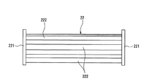
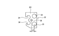
レール側軌道溝14とスライダ側軌道溝17との間に介在するボール13は、スライダ本体15に組み付けられた二つの樹脂製転動体保持器22(図2参照)によってスライダ本体側に保持されている。これらの転動体保持器22はスライダ本体15とエンドキャップ16との間に介装される二つのプレート部221(図4参照)を有しており、各プレート部221には、前述した転動体戻り路19と方向転換路20とを接続するための通路接続孔23(図5参照)が二つずつ形成されているとともに、前述した転動体負荷転動路18と方向転換路20とを接続するための通路接続孔24(図5参照)が二つずつ形成されている。なお、転動体保持器22の二つのプレート部221の間には、レール側軌道溝14とスライダ側軌道溝17との間に介在するボール13をスライダ側に保持する転動体保持部222(図4参照)が案内レール11に沿って樹脂成形されている。
The
リターンガイド162は転動体保持器22のプレート部221に当接する平面部162a(図6参照)を有しており、この平面部162aには、転動体保持器22のプレート部221に形成された位置決め用貫通孔25(図5参照)に嵌合して通路接続孔23の中心を転動体戻り路19及び方向転換路20の中心に一致させるための円柱状の位置決め用突起26が設けられているとともに、転動体保持器22のプレート部221に形成された通路接続孔24及びスライダ本体15に形成された転動体戻り路19に嵌合する半円筒状の位置決め用突起27がそれぞれ二個ずつ設けられている。
The
位置決め用突起26は転動体保持器22のプレート部221に形成された通路接続孔23と位置決め用貫通孔25との中心間距離L2(図7参照)とすると、位置決め用突起26と方向転換路20との中心間距離をL1(図6参照)がL1>L2となるようにリターンガイド162に設けられている。なお、上述した中心間距離L1とL2との差分量は0.2mm以下とすることが望ましい。
If the
このような構成において、スライダ本体15に転動体保持器22を組み付けた後、リターンガイド162に設けられた位置決め用突起26を転動体保持器22のプレート部221に形成された位置決め用貫通孔25に嵌め入れると共にリターンガイド162に設けられた位置決め用突起27を転動体保持器22のプレート部221に形成された通路接続孔24及びスライダ本体15の転動体戻り路19に嵌め入れると、転動体保持器22のプレート部221に形成された通路接続孔23の中心がスライダ本体15に形成された転動体戻り路19及びエンドキャップ本体161とリターンガイド162との間に形成された方向転換路20の中心と一致する。これにより、転動体保持器22に成形誤差があってもボール13の滑らかな転がり運動を阻害するような段差がスライダ12の転動体循環路に発生することがないので、転動体保持器22の成形誤差により騒音特性が悪化したり作動性が低下したりすることを防止することができる。
In such a configuration, after the rolling
また、リターンガイド162に設けた位置決め用突起26と方向転換路20との中心間距離L1を転動体保持器22のプレート部221に設けた位置決め用貫通孔25とスライダ本体15に形成された転動体戻り路19との中心間距離L2より小さい値とすることで、転動体保持器22の転動体保持部222がエンドキャップ16によってスライダ本体15の内側面側に押圧される。これにより、転動体保持器22がスライダ本体15に強固に固定される。また、L1とL2との寸法差を適宜設定することにより、スライダ本体15への転動体保持器22の押圧力を変化させることができるが、過大な押圧力は押圧部での部品の変形や破損の可能性があり、組付け性も考慮すると、L1とL2との寸法差は0.2mm以下とすることが好ましい。
Further, the center-to-center distance L1 between the positioning
また、リターンガイド162に設けた位置決め用突起26は、外周面をスライダ本体の係止部とし、内周面を転動体循環R部案内面20a(図6参照)としており、さらにスライダ本体15の転動体戻り路19にはスリーブ21が挿入されており、スリーブ21の外周面を同一の周面としてスリーブ21とエンドキャップ16とを繋いでいる。これにより同一面を使って、転動体循環路を構成するエンドキャップ16とスリーブ21を位置決めするので、転動体循環R部案内面20aとスリーブ21内の転動体戻り路とを高精度に接続することができ、作動性及び騒音特性をより一層向上させることができる。
(実施形態2)
次に、図8〜図10を参照して本発明の第2実施形態について説明する。なお、図1〜図7に示したものと同一部分には同一符号を付し、その詳細な説明は省略する。
Further, the
(Embodiment 2)
Next, a second embodiment of the present invention will be described with reference to FIGS. In addition, the same code | symbol is attached | subjected to the same part as what was shown in FIGS. 1-7, and the detailed description is abbreviate | omitted.
図8に示すように、リターンガイド162は転動体保持器22のプレート部221(図9参照)に当接する平面部162aを有しており、この平面部162aには、通路接続孔23及び転動体戻り路19に嵌合して通路接続孔23の中心を転動体戻り路19及び方向転換路20の中心に一致させるための半円筒状の位置決め用突起27がそれぞれ二個ずつ設けられているとともに、通路接続孔24及び転動体負荷転動路18に嵌合して通路接続孔24の中心を転動体負荷転動路18及び方向転換路20の中心に一致させるための円弧状の位置決め用突起28がそれぞれ二個ずつ設けられている。
As shown in FIG. 8, the
転動体戻り路19はスライダ本体15に形成された貫通孔15a(図10参照)に樹脂製スリーブ21を挿入して形成されている。
通路接続孔23及び通路接続孔24は、リターンガイド162の幅をL3(図8参照)とすると、通路接続孔23と通路接続孔24との中心間距離L4(図9参照)がL3>L4となるように転動体保持器22のプレート部221に形成されている。また、位置決め用突起27はスライダ本体15に形成された貫通孔15aの半径をR2とすると、R2より小さい曲率半径R1(図8参照)で半円筒状に形成されている。
The rolling
When the width of the
このような構成において、スライダ本体15に転動体保持器22を組み付けた後、リターンガイド162に設けられた位置決め用突起27を転動体保持器22のプレート部221に形成された通路接続孔23及びスライダ本体15内に形成された転動体戻り路19に嵌め入れるとともに、リターンガイド162に設けられた位置決め用突起28を転動体保持器22のプレート部221に形成された通路接続孔24及び転動体負荷転動路18に嵌め入れると、転動体保持器22のプレート部221に形成された通路接続孔23の中心がスライダ本体15内に形成された転動体戻り路19及びエンドキャップ本体161とリターンガイド162との間に形成された方向転換路20の中心に一致するとともに、転動体保持器22のプレート部221に形成された通路接続孔24の中心が転動体負荷転動路18及び方向転換路20の中心に一致する。これにより、転動体保持器22に成形誤差があってもボール13の滑らかな転がり運動を阻害するような段差がスライダ12の転動体循環路に発生することがないので、転動体保持器22の成形誤差により騒音特性が悪化したり作動性が低下したりすることを防止することができる。
In such a configuration, after the rolling
また、リターンガイド162の幅L3を転動体保持器22の通路接続孔23と通路接続孔24との中心間距離L4より小さい値としたことで、転動体保持器22の転動体保持部222がエンドキャップ16によってスライダ本体15の内側面側に押圧される。これにより、転動体保持器22が強固にスライダ本体15に固定される。また、リターンガイド162に設けた位置決め用突起27,28を案内レールの軌道溝側に設け、レール側軌道溝でスライダ本体端面とリターンガイド端面とが直接接合されている。そのため、前述した第1実施形態に対して、転動体保持器22に転動体循環路が構成されないため、段差の発生を抑制するように高い位置合せ精度が要求される部品の継ぎ部が減り、生産性、作動性及び騒音特性に有利となる。
Further, the width L3 of the
また、転動体保持器22をリターンガイド162で押圧する際に、転動体戻り路での転動体保持器22とリターンガイド162との接触による押圧不足を回避するため、位置決め突起27の曲率半径R1を貫通孔15aの半径R2よりも小さい値となっている。ここで、位置決め突起27は、本実施形態のように、半円筒状に限られるものではなく、円弧部をDカット形状に切り欠いた直線部で位置合せを行ってもよい。なお、本実施形態では転動体保持器22の転動体保持部とスライダ本体内側面とが接触しているが、スライダ本体貫通孔15aおよび/または転動体保持器22および/またはリターンガイド162によって位置決めされるエンドキャップ16が押圧による位置合せ部の変形の影響を回避するために、転動体保持器22の転動体保持部とスライダ本体内側面とが接触せずに、転動体保持器22がリターンガイド162との干渉によってスライダ本体15に位置決めされてもよい。
Further, when pressing the
(実施形態3)
次に、本発明の第3実施形態を図11〜図13に示す。本発明の第3実施形態における転動体保持器22は、転動体保持部222がスライダ本体の内側面に対して凸状に湾曲するように樹脂成形されている。このような転動体保持器を使用することで、前述した第1及び第2実施形態のように、各部品の位置決め間寸法に寸法差を与えなくても転動体保持器22の転動体保持部222をスライダ本体の内側面に押圧することが可能となり、第1及び第2実施形態よりも簡易な設計で容易に押圧可能となり、各部品の位置合せ部の寸法誤差も緩和できるため、生産性の面で一層有利となる。また、本実施形態の転動体保持器22は、転動体保持部222のスライダ本体内側面への成形による変形をスライダ本体内側面によって矯正できるため、生産性の面でも有利となる。なお、転動体保持部222の変形方向は図示しない例に限られるものではなく、転動体保持部とスライダ本体内側面との接触位置を例えば図13に示すような位置とし、転動体保持部222が矢印方向の変形の設定としてもよい。スライダ本体内側面によって、転動体保持部の変形を矯正可能となることが重要である。さらに、軌道溝側縁に設けた転動体保持部は全てがスライダ本体内側面に接してもよいし、その一部が接していてもよい。さらに、長手方向全域にわたって保持部とベアリング内側面は接触してもよいし、その一部が接していてもよい。
(Embodiment 3)
Next, a third embodiment of the present invention is shown in FIGS. The rolling
11 案内レール
12 スライダ
13 ボール(転動体)
14 レール側軌道溝
15 スライダ本体
16 エンドキャップ
161 エンドキャップ本体
162 リターンガイド
17 スライダ側軌道溝
18 転動体負荷転動路
19 転動体戻り路
20 方向転換路
22 転動体保持器
221 プレート部
222 転動体保持部
23,24 通路接続孔
26,27,28 位置決め用突起
25 位置決め用貫通孔
11
14 Rail-
Claims (3)
前記リターンガイドと前記転動体保持器を前記スライダ本体に組み込むことによって、前記リターンガイドと前記転動体保持器が互いに干渉して位置決めされ、前記転動体保持部の少なくとも一部が前記スライダ本体の内側面に弾性的に接触していることを特徴とする直動案内装置。 A guide rail, a slider body having a plurality of slider-side track grooves facing the rail-side track grooves formed on the left side surface and the right side surface of the guide rail, and between the rail-side track groove and the slider-side track groove The direction of the rolling elements loaded on the rolling element load rolling path, the two end cap bodies mounted on the slider body, and the rolling elements rolling on the rolling element load rolling path are changed. A plurality of return guides that form a direction changing path between the rail-side raceway groove and the slider-side raceway groove on the slider body side. Two rolling element holders made of resin, two plate portions interposed between the slider main body and the end cap, and the plate along the guide rail. And a rolling element holding portion formed between the portions, and the return guide is fitted in a rolling element return path formed in the slider body and has a positioning projection with the slider body. In the guidance device,
By incorporating the return guide and the rolling element holder into the slider main body, the return guide and the rolling element holder are positioned to interfere with each other, and at least a part of the rolling element holding portion is located inside the slider main body. A linear motion guide device characterized by elastically contacting a side surface.
Priority Applications (5)
| Application Number | Priority Date | Filing Date | Title |
|---|---|---|---|
| JP2006122341A JP4682910B2 (en) | 2006-04-26 | 2006-04-26 | Linear motion guide device |
| PCT/JP2006/309604 WO2006121167A1 (en) | 2005-05-12 | 2006-05-12 | Linear guide device |
| US11/793,455 US7862235B2 (en) | 2005-05-12 | 2006-05-12 | Linear guide device |
| CN2006800013414A CN101069025B (en) | 2005-05-12 | 2006-05-12 | Linear guide device |
| EP06746351A EP1881214A1 (en) | 2005-05-12 | 2006-05-12 | Linear guide device |
Applications Claiming Priority (1)
| Application Number | Priority Date | Filing Date | Title |
|---|---|---|---|
| JP2006122341A JP4682910B2 (en) | 2006-04-26 | 2006-04-26 | Linear motion guide device |
Publications (3)
| Publication Number | Publication Date |
|---|---|
| JP2007292240A JP2007292240A (en) | 2007-11-08 |
| JP2007292240A5 JP2007292240A5 (en) | 2009-01-22 |
| JP4682910B2 true JP4682910B2 (en) | 2011-05-11 |
Family
ID=38763039
Family Applications (1)
| Application Number | Title | Priority Date | Filing Date |
|---|---|---|---|
| JP2006122341A Active JP4682910B2 (en) | 2005-05-12 | 2006-04-26 | Linear motion guide device |
Country Status (1)
| Country | Link |
|---|---|
| JP (1) | JP4682910B2 (en) |
Families Citing this family (2)
| Publication number | Priority date | Publication date | Assignee | Title |
|---|---|---|---|---|
| JP5373462B2 (en) * | 2009-04-15 | 2013-12-18 | Thk株式会社 | Exercise guidance device |
| JP2014145457A (en) * | 2013-01-30 | 2014-08-14 | Nsk Ltd | Linear guide device |
Family Cites Families (4)
| Publication number | Priority date | Publication date | Assignee | Title |
|---|---|---|---|---|
| JPS58182928A (en) * | 1982-04-20 | 1983-10-26 | Nec Corp | Radio repeating system |
| JPS59181331U (en) * | 1983-05-23 | 1984-12-04 | 株式会社 椿本精工 | Ball cage for linear motion ball bearings |
| JPS6215623U (en) * | 1985-07-12 | 1987-01-30 | ||
| JP3571911B2 (en) * | 1997-06-16 | 2004-09-29 | Thk株式会社 | Linear motion guide device |
-
2006
- 2006-04-26 JP JP2006122341A patent/JP4682910B2/en active Active
Also Published As
| Publication number | Publication date |
|---|---|
| JP2007292240A (en) | 2007-11-08 |
Similar Documents
| Publication | Publication Date | Title |
|---|---|---|
| US20130055839A1 (en) | Ball screw with sectional circulating assemblies | |
| US7862235B2 (en) | Linear guide device | |
| JP5316700B2 (en) | Linear guide device | |
| JP4682910B2 (en) | Linear motion guide device | |
| JP5672895B2 (en) | Attachment for temporary shaft of linear motion guide device | |
| US6371648B1 (en) | Linear guide device | |
| JP4682911B2 (en) | Linear motion guide device | |
| JP2008057698A (en) | Sleeve for return passage of linear guide device, circulation passage forming member and linear guide device | |
| KR100742908B1 (en) | Sliding apparatus | |
| JP2006002842A (en) | Straight motion guide bearing device | |
| JP5984266B2 (en) | Chain guide | |
| CN111043158A (en) | Tapered roller bearing | |
| JP2006234032A (en) | Linear guide bearing device | |
| JP2018138816A (en) | Linear motion device | |
| JP2009287701A (en) | Roller type ball screw | |
| JP2008223878A (en) | Linear motion guide | |
| JP4770261B2 (en) | Linear motion guide device | |
| US20080134225A1 (en) | Disc guide of disc carrying device | |
| US20200191246A1 (en) | Ball Screw | |
| JP6922703B2 (en) | Linear guidance device and its assembly method | |
| JP2014211214A (en) | Linear guide device | |
| JP6131530B2 (en) | Linear guide device | |
| JP4185187B2 (en) | Slide device for linear sliding | |
| JP2005256997A (en) | Structure of slide block of linear guide way | |
| JP5272350B2 (en) | Linear motion guide device |
Legal Events
| Date | Code | Title | Description |
|---|---|---|---|
| A521 | Written amendment |
Free format text: JAPANESE INTERMEDIATE CODE: A523 Effective date: 20081202 |
|
| A621 | Written request for application examination |
Free format text: JAPANESE INTERMEDIATE CODE: A621 Effective date: 20081202 |
|
| A131 | Notification of reasons for refusal |
Free format text: JAPANESE INTERMEDIATE CODE: A131 Effective date: 20100914 |
|
| A521 | Written amendment |
Free format text: JAPANESE INTERMEDIATE CODE: A523 Effective date: 20101111 |
|
| TRDD | Decision of grant or rejection written | ||
| A01 | Written decision to grant a patent or to grant a registration (utility model) |
Free format text: JAPANESE INTERMEDIATE CODE: A01 Effective date: 20110111 |
|
| A01 | Written decision to grant a patent or to grant a registration (utility model) |
Free format text: JAPANESE INTERMEDIATE CODE: A01 |
|
| A61 | First payment of annual fees (during grant procedure) |
Free format text: JAPANESE INTERMEDIATE CODE: A61 Effective date: 20110124 |
|
| FPAY | Renewal fee payment (event date is renewal date of database) |
Free format text: PAYMENT UNTIL: 20140218 Year of fee payment: 3 |
|
| R150 | Certificate of patent or registration of utility model |
Ref document number: 4682910 Country of ref document: JP Free format text: JAPANESE INTERMEDIATE CODE: R150 Free format text: JAPANESE INTERMEDIATE CODE: R150 |