JP4680190B2 - Injection device - Google Patents
Injection device Download PDFInfo
- Publication number
- JP4680190B2 JP4680190B2 JP2006521759A JP2006521759A JP4680190B2 JP 4680190 B2 JP4680190 B2 JP 4680190B2 JP 2006521759 A JP2006521759 A JP 2006521759A JP 2006521759 A JP2006521759 A JP 2006521759A JP 4680190 B2 JP4680190 B2 JP 4680190B2
- Authority
- JP
- Japan
- Prior art keywords
- housing
- shield
- driver
- injector
- needle
- Prior art date
- Legal status (The legal status is an assumption and is not a legal conclusion. Google has not performed a legal analysis and makes no representation as to the accuracy of the status listed.)
- Active
Links
- 238000002347 injection Methods 0.000 title claims description 68
- 239000007924 injection Substances 0.000 title claims description 68
- 230000007246 mechanism Effects 0.000 claims description 41
- 230000033001 locomotion Effects 0.000 claims description 29
- 238000007906 compression Methods 0.000 claims description 9
- 230000006835 compression Effects 0.000 claims description 9
- 229940079593 drug Drugs 0.000 description 41
- 239000003814 drug Substances 0.000 description 41
- 238000006073 displacement reaction Methods 0.000 description 35
- 238000004448 titration Methods 0.000 description 34
- 210000001519 tissue Anatomy 0.000 description 16
- 238000003780 insertion Methods 0.000 description 15
- 230000037431 insertion Effects 0.000 description 15
- 238000000034 method Methods 0.000 description 15
- 230000001681 protective effect Effects 0.000 description 14
- 238000010586 diagram Methods 0.000 description 13
- 239000012530 fluid Substances 0.000 description 12
- 230000006870 function Effects 0.000 description 12
- 230000008569 process Effects 0.000 description 12
- 238000012377 drug delivery Methods 0.000 description 9
- 239000002699 waste material Substances 0.000 description 9
- 238000000418 atomic force spectrum Methods 0.000 description 8
- 230000009471 action Effects 0.000 description 6
- 229940090047 auto-injector Drugs 0.000 description 6
- 230000006378 damage Effects 0.000 description 5
- 239000011521 glass Substances 0.000 description 5
- 208000014674 injury Diseases 0.000 description 5
- 239000004033 plastic Substances 0.000 description 5
- 239000000243 solution Substances 0.000 description 5
- 208000027418 Wounds and injury Diseases 0.000 description 4
- 238000005452 bending Methods 0.000 description 4
- 230000003993 interaction Effects 0.000 description 4
- 239000007788 liquid Substances 0.000 description 4
- 230000014759 maintenance of location Effects 0.000 description 4
- 108090000623 proteins and genes Proteins 0.000 description 4
- 102000004169 proteins and genes Human genes 0.000 description 4
- 230000001960 triggered effect Effects 0.000 description 4
- 206010034912 Phobia Diseases 0.000 description 3
- 239000003146 anticoagulant agent Substances 0.000 description 3
- 229940127219 anticoagulant drug Drugs 0.000 description 3
- 239000002246 antineoplastic agent Substances 0.000 description 3
- 230000008901 benefit Effects 0.000 description 3
- -1 bushings Substances 0.000 description 3
- 210000000078 claw Anatomy 0.000 description 3
- 239000000203 mixture Substances 0.000 description 3
- 238000004806 packaging method and process Methods 0.000 description 3
- 208000019899 phobic disease Diseases 0.000 description 3
- 239000000047 product Substances 0.000 description 3
- 108060001064 Calcitonin Proteins 0.000 description 2
- 108090000394 Erythropoietin Proteins 0.000 description 2
- 102000003951 Erythropoietin Human genes 0.000 description 2
- 102000018997 Growth Hormone Human genes 0.000 description 2
- 108010051696 Growth Hormone Proteins 0.000 description 2
- 102000038461 Growth Hormone-Releasing Hormone Human genes 0.000 description 2
- 239000000095 Growth Hormone-Releasing Hormone Substances 0.000 description 2
- 206010069803 Injury associated with device Diseases 0.000 description 2
- 108090000723 Insulin-Like Growth Factor I Proteins 0.000 description 2
- RJKFOVLPORLFTN-LEKSSAKUSA-N Progesterone Chemical compound C1CC2=CC(=O)CC[C@]2(C)[C@@H]2[C@@H]1[C@@H]1CC[C@H](C(=O)C)[C@@]1(C)CC2 RJKFOVLPORLFTN-LEKSSAKUSA-N 0.000 description 2
- 101710142969 Somatoliberin Proteins 0.000 description 2
- 102000013275 Somatomedins Human genes 0.000 description 2
- 102000003978 Tissue Plasminogen Activator Human genes 0.000 description 2
- 108090000373 Tissue Plasminogen Activator Proteins 0.000 description 2
- 230000004913 activation Effects 0.000 description 2
- 229940035676 analgesics Drugs 0.000 description 2
- 239000000730 antalgic agent Substances 0.000 description 2
- 230000002686 anti-diuretic effect Effects 0.000 description 2
- 229940124538 antidiuretic agent Drugs 0.000 description 2
- 238000013459 approach Methods 0.000 description 2
- 239000002738 chelating agent Substances 0.000 description 2
- 238000013016 damping Methods 0.000 description 2
- 230000007423 decrease Effects 0.000 description 2
- 238000013461 design Methods 0.000 description 2
- 238000001514 detection method Methods 0.000 description 2
- 230000000694 effects Effects 0.000 description 2
- 229940105423 erythropoietin Drugs 0.000 description 2
- 238000009472 formulation Methods 0.000 description 2
- 229940088597 hormone Drugs 0.000 description 2
- 239000005556 hormone Substances 0.000 description 2
- NOESYZHRGYRDHS-UHFFFAOYSA-N insulin Chemical compound N1C(=O)C(NC(=O)C(CCC(N)=O)NC(=O)C(CCC(O)=O)NC(=O)C(C(C)C)NC(=O)C(NC(=O)CN)C(C)CC)CSSCC(C(NC(CO)C(=O)NC(CC(C)C)C(=O)NC(CC=2C=CC(O)=CC=2)C(=O)NC(CCC(N)=O)C(=O)NC(CC(C)C)C(=O)NC(CCC(O)=O)C(=O)NC(CC(N)=O)C(=O)NC(CC=2C=CC(O)=CC=2)C(=O)NC(CSSCC(NC(=O)C(C(C)C)NC(=O)C(CC(C)C)NC(=O)C(CC=2C=CC(O)=CC=2)NC(=O)C(CC(C)C)NC(=O)C(C)NC(=O)C(CCC(O)=O)NC(=O)C(C(C)C)NC(=O)C(CC(C)C)NC(=O)C(CC=2NC=NC=2)NC(=O)C(CO)NC(=O)CNC2=O)C(=O)NCC(=O)NC(CCC(O)=O)C(=O)NC(CCCNC(N)=N)C(=O)NCC(=O)NC(CC=3C=CC=CC=3)C(=O)NC(CC=3C=CC=CC=3)C(=O)NC(CC=3C=CC(O)=CC=3)C(=O)NC(C(C)O)C(=O)N3C(CCC3)C(=O)NC(CCCCN)C(=O)NC(C)C(O)=O)C(=O)NC(CC(N)=O)C(O)=O)=O)NC(=O)C(C(C)CC)NC(=O)C(CO)NC(=O)C(C(C)O)NC(=O)C1CSSCC2NC(=O)C(CC(C)C)NC(=O)C(NC(=O)C(CCC(N)=O)NC(=O)C(CC(N)=O)NC(=O)C(NC(=O)C(N)CC=1C=CC=CC=1)C(C)C)CC1=CN=CN1 NOESYZHRGYRDHS-UHFFFAOYSA-N 0.000 description 2
- 230000007257 malfunction Effects 0.000 description 2
- 239000000463 material Substances 0.000 description 2
- BQJCRHHNABKAKU-KBQPJGBKSA-N morphine Chemical compound O([C@H]1[C@H](C=C[C@H]23)O)C4=C5[C@@]12CCN(C)[C@@H]3CC5=CC=C4O BQJCRHHNABKAKU-KBQPJGBKSA-N 0.000 description 2
- 229940094443 oxytocics prostaglandins Drugs 0.000 description 2
- 206010033675 panniculitis Diseases 0.000 description 2
- 230000035515 penetration Effects 0.000 description 2
- 230000000704 physical effect Effects 0.000 description 2
- OXCMYAYHXIHQOA-UHFFFAOYSA-N potassium;[2-butyl-5-chloro-3-[[4-[2-(1,2,4-triaza-3-azanidacyclopenta-1,4-dien-5-yl)phenyl]phenyl]methyl]imidazol-4-yl]methanol Chemical compound [K+].CCCCC1=NC(Cl)=C(CO)N1CC1=CC=C(C=2C(=CC=CC=2)C2=N[N-]N=N2)C=C1 OXCMYAYHXIHQOA-UHFFFAOYSA-N 0.000 description 2
- 230000036316 preload Effects 0.000 description 2
- 230000002028 premature Effects 0.000 description 2
- 238000002360 preparation method Methods 0.000 description 2
- 102000004196 processed proteins & peptides Human genes 0.000 description 2
- 108090000765 processed proteins & peptides Proteins 0.000 description 2
- 150000003180 prostaglandins Chemical class 0.000 description 2
- 230000009467 reduction Effects 0.000 description 2
- 230000004044 response Effects 0.000 description 2
- 239000000932 sedative agent Substances 0.000 description 2
- 229940125723 sedative agent Drugs 0.000 description 2
- 230000003068 static effect Effects 0.000 description 2
- 238000007920 subcutaneous administration Methods 0.000 description 2
- 210000004304 subcutaneous tissue Anatomy 0.000 description 2
- 229960000187 tissue plasminogen activator Drugs 0.000 description 2
- 238000012546 transfer Methods 0.000 description 2
- FELGMEQIXOGIFQ-CYBMUJFWSA-N (3r)-9-methyl-3-[(2-methylimidazol-1-yl)methyl]-2,3-dihydro-1h-carbazol-4-one Chemical compound CC1=NC=CN1C[C@@H]1C(=O)C(C=2C(=CC=CC=2)N2C)=C2CC1 FELGMEQIXOGIFQ-CYBMUJFWSA-N 0.000 description 1
- LEBVLXFERQHONN-UHFFFAOYSA-N 1-butyl-N-(2,6-dimethylphenyl)piperidine-2-carboxamide Chemical compound CCCCN1CCCCC1C(=O)NC1=C(C)C=CC=C1C LEBVLXFERQHONN-UHFFFAOYSA-N 0.000 description 1
- WJFKNYWRSNBZNX-UHFFFAOYSA-N 10H-phenothiazine Chemical compound C1=CC=C2NC3=CC=CC=C3SC2=C1 WJFKNYWRSNBZNX-UHFFFAOYSA-N 0.000 description 1
- VOXZDWNPVJITMN-ZBRFXRBCSA-N 17β-estradiol Chemical compound OC1=CC=C2[C@H]3CC[C@](C)([C@H](CC4)O)[C@@H]4[C@@H]3CCC2=C1 VOXZDWNPVJITMN-ZBRFXRBCSA-N 0.000 description 1
- SGTNSNPWRIOYBX-UHFFFAOYSA-N 2-(3,4-dimethoxyphenyl)-5-{[2-(3,4-dimethoxyphenyl)ethyl](methyl)amino}-2-(propan-2-yl)pentanenitrile Chemical compound C1=C(OC)C(OC)=CC=C1CCN(C)CCCC(C#N)(C(C)C)C1=CC=C(OC)C(OC)=C1 SGTNSNPWRIOYBX-UHFFFAOYSA-N 0.000 description 1
- USSIQXCVUWKGNF-UHFFFAOYSA-N 6-(dimethylamino)-4,4-diphenylheptan-3-one Chemical compound C=1C=CC=CC=1C(CC(C)N(C)C)(C(=O)CC)C1=CC=CC=C1 USSIQXCVUWKGNF-UHFFFAOYSA-N 0.000 description 1
- 229930000680 A04AD01 - Scopolamine Natural products 0.000 description 1
- 208000030507 AIDS Diseases 0.000 description 1
- 208000012260 Accidental injury Diseases 0.000 description 1
- 208000019901 Anxiety disease Diseases 0.000 description 1
- 208000006096 Attention Deficit Disorder with Hyperactivity Diseases 0.000 description 1
- 208000036864 Attention deficit/hyperactivity disease Diseases 0.000 description 1
- 108010006654 Bleomycin Proteins 0.000 description 1
- 102000055006 Calcitonin Human genes 0.000 description 1
- 229940123150 Chelating agent Drugs 0.000 description 1
- 108010071942 Colony-Stimulating Factors Proteins 0.000 description 1
- 102000007644 Colony-Stimulating Factors Human genes 0.000 description 1
- PMATZTZNYRCHOR-CGLBZJNRSA-N Cyclosporin A Chemical compound CC[C@@H]1NC(=O)[C@H]([C@H](O)[C@H](C)C\C=C\C)N(C)C(=O)[C@H](C(C)C)N(C)C(=O)[C@H](CC(C)C)N(C)C(=O)[C@H](CC(C)C)N(C)C(=O)[C@@H](C)NC(=O)[C@H](C)NC(=O)[C@H](CC(C)C)N(C)C(=O)[C@H](C(C)C)NC(=O)[C@H](CC(C)C)N(C)C(=O)CN(C)C1=O PMATZTZNYRCHOR-CGLBZJNRSA-N 0.000 description 1
- 229930105110 Cyclosporin A Natural products 0.000 description 1
- 108010036949 Cyclosporine Proteins 0.000 description 1
- 108010041986 DNA Vaccines Proteins 0.000 description 1
- 229940021995 DNA vaccine Drugs 0.000 description 1
- 108010000437 Deamino Arginine Vasopressin Proteins 0.000 description 1
- 206010073753 Fear of injection Diseases 0.000 description 1
- 239000004606 Fillers/Extenders Substances 0.000 description 1
- GHASVSINZRGABV-UHFFFAOYSA-N Fluorouracil Chemical compound FC1=CNC(=O)NC1=O GHASVSINZRGABV-UHFFFAOYSA-N 0.000 description 1
- WQZGKKKJIJFFOK-GASJEMHNSA-N Glucose Chemical compound OC[C@H]1OC(O)[C@H](O)[C@@H](O)[C@@H]1O WQZGKKKJIJFFOK-GASJEMHNSA-N 0.000 description 1
- HTTJABKRGRZYRN-UHFFFAOYSA-N Heparin Chemical compound OC1C(NC(=O)C)C(O)OC(COS(O)(=O)=O)C1OC1C(OS(O)(=O)=O)C(O)C(OC2C(C(OS(O)(=O)=O)C(OC3C(C(O)C(O)C(O3)C(O)=O)OS(O)(=O)=O)C(CO)O2)NS(O)(=O)=O)C(C(O)=O)O1 HTTJABKRGRZYRN-UHFFFAOYSA-N 0.000 description 1
- 102000007625 Hirudins Human genes 0.000 description 1
- 108010007267 Hirudins Proteins 0.000 description 1
- 101000904173 Homo sapiens Progonadoliberin-1 Proteins 0.000 description 1
- 102000002265 Human Growth Hormone Human genes 0.000 description 1
- 108010000521 Human Growth Hormone Proteins 0.000 description 1
- 239000000854 Human Growth Hormone Substances 0.000 description 1
- STECJAGHUSJQJN-GAUPFVANSA-N Hyoscine Natural products C1([C@H](CO)C(=O)OC2C[C@@H]3N([C@H](C2)[C@@H]2[C@H]3O2)C)=CC=CC=C1 STECJAGHUSJQJN-GAUPFVANSA-N 0.000 description 1
- 108090001061 Insulin Proteins 0.000 description 1
- 102000004877 Insulin Human genes 0.000 description 1
- 108010005714 Interferon beta-1b Proteins 0.000 description 1
- 102000006992 Interferon-alpha Human genes 0.000 description 1
- 108010047761 Interferon-alpha Proteins 0.000 description 1
- 108090000467 Interferon-beta Proteins 0.000 description 1
- 102000003996 Interferon-beta Human genes 0.000 description 1
- 102000008070 Interferon-gamma Human genes 0.000 description 1
- 108010074328 Interferon-gamma Proteins 0.000 description 1
- 108010050904 Interferons Proteins 0.000 description 1
- 102000014150 Interferons Human genes 0.000 description 1
- 102000000588 Interleukin-2 Human genes 0.000 description 1
- 108010002350 Interleukin-2 Proteins 0.000 description 1
- 102000015696 Interleukins Human genes 0.000 description 1
- 108010063738 Interleukins Proteins 0.000 description 1
- 108010000817 Leuprolide Proteins 0.000 description 1
- JAQUASYNZVUNQP-USXIJHARSA-N Levorphanol Chemical compound C1C2=CC=C(O)C=C2[C@]23CCN(C)[C@H]1[C@@H]2CCCC3 JAQUASYNZVUNQP-USXIJHARSA-N 0.000 description 1
- NNJVILVZKWQKPM-UHFFFAOYSA-N Lidocaine Chemical compound CCN(CC)CC(=O)NC1=C(C)C=CC=C1C NNJVILVZKWQKPM-UHFFFAOYSA-N 0.000 description 1
- DUGOZIWVEXMGBE-UHFFFAOYSA-N Methylphenidate Chemical compound C=1C=CC=CC=1C(C(=O)OC)C1CCCCN1 DUGOZIWVEXMGBE-UHFFFAOYSA-N 0.000 description 1
- 208000019695 Migraine disease Diseases 0.000 description 1
- STECJAGHUSJQJN-UHFFFAOYSA-N N-Methyl-scopolamin Natural products C1C(C2C3O2)N(C)C3CC1OC(=O)C(CO)C1=CC=CC=C1 STECJAGHUSJQJN-UHFFFAOYSA-N 0.000 description 1
- CMWTZPSULFXXJA-UHFFFAOYSA-N Naproxen Natural products C1=C(C(C)C(O)=O)C=CC2=CC(OC)=CC=C21 CMWTZPSULFXXJA-UHFFFAOYSA-N 0.000 description 1
- 208000012266 Needlestick injury Diseases 0.000 description 1
- SNIOPGDIGTZGOP-UHFFFAOYSA-N Nitroglycerin Chemical compound [O-][N+](=O)OCC(O[N+]([O-])=O)CO[N+]([O-])=O SNIOPGDIGTZGOP-UHFFFAOYSA-N 0.000 description 1
- 239000000006 Nitroglycerin Substances 0.000 description 1
- UQCNKQCJZOAFTQ-ISWURRPUSA-N Oxymorphone Chemical compound O([C@H]1C(CC[C@]23O)=O)C4=C5[C@@]12CCN(C)[C@@H]3CC5=CC=C4O UQCNKQCJZOAFTQ-ISWURRPUSA-N 0.000 description 1
- 102400000050 Oxytocin Human genes 0.000 description 1
- 101800000989 Oxytocin Proteins 0.000 description 1
- XNOPRXBHLZRZKH-UHFFFAOYSA-N Oxytocin Natural products N1C(=O)C(N)CSSCC(C(=O)N2C(CCC2)C(=O)NC(CC(C)C)C(=O)NCC(N)=O)NC(=O)C(CC(N)=O)NC(=O)C(CCC(N)=O)NC(=O)C(C(C)CC)NC(=O)C1CC1=CC=C(O)C=C1 XNOPRXBHLZRZKH-UHFFFAOYSA-N 0.000 description 1
- 102100024028 Progonadoliberin-1 Human genes 0.000 description 1
- 102000005157 Somatostatin Human genes 0.000 description 1
- 108010056088 Somatostatin Proteins 0.000 description 1
- 101000996723 Sus scrofa Gonadotropin-releasing hormone receptor Proteins 0.000 description 1
- GXBMIBRIOWHPDT-UHFFFAOYSA-N Vasopressin Natural products N1C(=O)C(CC=2C=C(O)C=CC=2)NC(=O)C(N)CSSCC(C(=O)N2C(CCC2)C(=O)NC(CCCN=C(N)N)C(=O)NCC(N)=O)NC(=O)C(CC(N)=O)NC(=O)C(CCC(N)=O)NC(=O)C1CC1=CC=CC=C1 GXBMIBRIOWHPDT-UHFFFAOYSA-N 0.000 description 1
- 108010004977 Vasopressins Proteins 0.000 description 1
- 102000002852 Vasopressins Human genes 0.000 description 1
- 239000002671 adjuvant Substances 0.000 description 1
- 239000005557 antagonist Substances 0.000 description 1
- 239000004004 anti-anginal agent Substances 0.000 description 1
- 230000003257 anti-anginal effect Effects 0.000 description 1
- 230000003474 anti-emetic effect Effects 0.000 description 1
- 229940124345 antianginal agent Drugs 0.000 description 1
- 239000003160 antidiuretic agent Substances 0.000 description 1
- 229940125683 antiemetic agent Drugs 0.000 description 1
- 239000002111 antiemetic agent Substances 0.000 description 1
- 239000000427 antigen Substances 0.000 description 1
- 102000036639 antigens Human genes 0.000 description 1
- 108091007433 antigens Proteins 0.000 description 1
- 239000002220 antihypertensive agent Substances 0.000 description 1
- 229940030600 antihypertensive agent Drugs 0.000 description 1
- 230000036506 anxiety Effects 0.000 description 1
- KBZOIRJILGZLEJ-LGYYRGKSSA-N argipressin Chemical compound C([C@H]1C(=O)N[C@@H](CCC(N)=O)C(=O)N[C@@H](CC(N)=O)C(=O)N[C@@H](CSSC[C@@H](C(N[C@@H](CC=2C=CC(O)=CC=2)C(=O)N1)=O)N)C(=O)N1[C@@H](CCC1)C(=O)N[C@@H](CCCN=C(N)N)C(=O)NCC(N)=O)C1=CC=CC=C1 KBZOIRJILGZLEJ-LGYYRGKSSA-N 0.000 description 1
- 230000001746 atrial effect Effects 0.000 description 1
- 208000015802 attention deficit-hyperactivity disease Diseases 0.000 description 1
- 229940049706 benzodiazepine Drugs 0.000 description 1
- 150000001557 benzodiazepines Chemical class 0.000 description 1
- 229940021459 betaseron Drugs 0.000 description 1
- 229960001561 bleomycin Drugs 0.000 description 1
- OYVAGSVQBOHSSS-UAPAGMARSA-O bleomycin A2 Chemical compound N([C@H](C(=O)N[C@H](C)[C@@H](O)[C@H](C)C(=O)N[C@@H]([C@H](O)C)C(=O)NCCC=1SC=C(N=1)C=1SC=C(N=1)C(=O)NCCC[S+](C)C)[C@@H](O[C@H]1[C@H]([C@@H](O)[C@H](O)[C@H](CO)O1)O[C@@H]1[C@H]([C@@H](OC(N)=O)[C@H](O)[C@@H](CO)O1)O)C=1N=CNC=1)C(=O)C1=NC([C@H](CC(N)=O)NC[C@H](N)C(N)=O)=NC(N)=C1C OYVAGSVQBOHSSS-UAPAGMARSA-O 0.000 description 1
- 239000012267 brine Substances 0.000 description 1
- 229960003150 bupivacaine Drugs 0.000 description 1
- RMRJXGBAOAMLHD-IHFGGWKQSA-N buprenorphine Chemical compound C([C@]12[C@H]3OC=4C(O)=CC=C(C2=4)C[C@@H]2[C@]11CC[C@]3([C@H](C1)[C@](C)(O)C(C)(C)C)OC)CN2CC1CC1 RMRJXGBAOAMLHD-IHFGGWKQSA-N 0.000 description 1
- 229960001736 buprenorphine Drugs 0.000 description 1
- IFKLAQQSCNILHL-QHAWAJNXSA-N butorphanol Chemical compound N1([C@@H]2CC3=CC=C(C=C3[C@@]3([C@]2(CCCC3)O)CC1)O)CC1CCC1 IFKLAQQSCNILHL-QHAWAJNXSA-N 0.000 description 1
- 229960001113 butorphanol Drugs 0.000 description 1
- 239000006227 byproduct Substances 0.000 description 1
- 229960004015 calcitonin Drugs 0.000 description 1
- BBBFJLBPOGFECG-VJVYQDLKSA-N calcitonin Chemical compound N([C@H](C(=O)N[C@@H](CC(C)C)C(=O)NCC(=O)N[C@@H](CCCCN)C(=O)N[C@@H](CC(C)C)C(=O)N[C@@H](CO)C(=O)N[C@@H](CCC(N)=O)C(=O)N[C@@H](CCC(O)=O)C(=O)N[C@@H](CC(C)C)C(=O)N[C@@H](CC=1NC=NC=1)C(=O)N[C@@H](CCCCN)C(=O)N[C@@H](CC(C)C)C(=O)N[C@@H](CCC(N)=O)C(=O)N[C@@H]([C@@H](C)O)C(=O)N[C@@H](CC=1C=CC(O)=CC=1)C(=O)N1[C@@H](CCC1)C(=O)N[C@@H](CCCNC(N)=N)C(=O)N[C@@H]([C@@H](C)O)C(=O)N[C@@H](CC(N)=O)C(=O)N[C@@H]([C@@H](C)O)C(=O)NCC(=O)N[C@@H](CO)C(=O)NCC(=O)N[C@@H]([C@@H](C)O)C(=O)N1[C@@H](CCC1)C(N)=O)C(C)C)C(=O)[C@@H]1CSSC[C@H](N)C(=O)N[C@@H](CO)C(=O)N[C@@H](CC(N)=O)C(=O)N[C@@H](CC(C)C)C(=O)N[C@@H](CO)C(=O)N[C@@H]([C@@H](C)O)C(=O)N1 BBBFJLBPOGFECG-VJVYQDLKSA-N 0.000 description 1
- 239000002327 cardiovascular agent Substances 0.000 description 1
- 229940125692 cardiovascular agent Drugs 0.000 description 1
- 210000003169 central nervous system Anatomy 0.000 description 1
- 230000008859 change Effects 0.000 description 1
- 230000000973 chemotherapeutic effect Effects 0.000 description 1
- 229960001265 ciclosporin Drugs 0.000 description 1
- 238000004891 communication Methods 0.000 description 1
- 239000002131 composite material Substances 0.000 description 1
- 238000011109 contamination Methods 0.000 description 1
- 229930182912 cyclosporin Natural products 0.000 description 1
- 229940127089 cytotoxic agent Drugs 0.000 description 1
- 230000001419 dependent effect Effects 0.000 description 1
- 229960004281 desmopressin Drugs 0.000 description 1
- NFLWUMRGJYTJIN-NXBWRCJVSA-N desmopressin Chemical compound C([C@H]1C(=O)N[C@H](C(N[C@@H](CC(N)=O)C(=O)N[C@@H](CSSCCC(=O)N[C@@H](CC=2C=CC(O)=CC=2)C(=O)N1)C(=O)N1[C@@H](CCC1)C(=O)N[C@@H](CCCNC(N)=N)C(=O)NCC(N)=O)=O)CCC(=O)N)C1=CC=CC=C1 NFLWUMRGJYTJIN-NXBWRCJVSA-N 0.000 description 1
- 229960001259 diclofenac Drugs 0.000 description 1
- DCOPUUMXTXDBNB-UHFFFAOYSA-N diclofenac Chemical compound OC(=O)CC1=CC=CC=C1NC1=C(Cl)C=CC=C1Cl DCOPUUMXTXDBNB-UHFFFAOYSA-N 0.000 description 1
- XYYVYLMBEZUESM-UHFFFAOYSA-N dihydrocodeine Natural products C1C(N(CCC234)C)C2C=CC(=O)C3OC2=C4C1=CC=C2OC XYYVYLMBEZUESM-UHFFFAOYSA-N 0.000 description 1
- 229960004166 diltiazem Drugs 0.000 description 1
- HSUGRBWQSSZJOP-RTWAWAEBSA-N diltiazem Chemical compound C1=CC(OC)=CC=C1[C@H]1[C@@H](OC(C)=O)C(=O)N(CCN(C)C)C2=CC=CC=C2S1 HSUGRBWQSSZJOP-RTWAWAEBSA-N 0.000 description 1
- 239000003085 diluting agent Substances 0.000 description 1
- 201000010099 disease Diseases 0.000 description 1
- 208000037265 diseases, disorders, signs and symptoms Diseases 0.000 description 1
- 239000002934 diuretic Substances 0.000 description 1
- FGXWKSZFVQUSTL-UHFFFAOYSA-N domperidone Chemical compound C12=CC=CC=C2NC(=O)N1CCCN(CC1)CCC1N1C2=CC=C(Cl)C=C2NC1=O FGXWKSZFVQUSTL-UHFFFAOYSA-N 0.000 description 1
- 229960001253 domperidone Drugs 0.000 description 1
- 229960003133 ergot alkaloid Drugs 0.000 description 1
- 229960005309 estradiol Drugs 0.000 description 1
- 229930182833 estradiol Natural products 0.000 description 1
- 229960002428 fentanyl Drugs 0.000 description 1
- PJMPHNIQZUBGLI-UHFFFAOYSA-N fentanyl Chemical compound C=1C=CC=CC=1N(C(=O)CC)C(CC1)CCN1CCC1=CC=CC=C1 PJMPHNIQZUBGLI-UHFFFAOYSA-N 0.000 description 1
- 229960002949 fluorouracil Drugs 0.000 description 1
- 229960001751 fluoxymesterone Drugs 0.000 description 1
- YLRFCQOZQXIBAB-RBZZARIASA-N fluoxymesterone Chemical compound C1CC2=CC(=O)CC[C@]2(C)[C@]2(F)[C@@H]1[C@@H]1CC[C@](C)(O)[C@@]1(C)C[C@@H]2O YLRFCQOZQXIBAB-RBZZARIASA-N 0.000 description 1
- 210000000245 forearm Anatomy 0.000 description 1
- 229940044627 gamma-interferon Drugs 0.000 description 1
- 238000001415 gene therapy Methods 0.000 description 1
- 229960003711 glyceryl trinitrate Drugs 0.000 description 1
- XLXSAKCOAKORKW-UHFFFAOYSA-N gonadorelin Chemical compound C1CCC(C(=O)NCC(N)=O)N1C(=O)C(CCCN=C(N)N)NC(=O)C(CC(C)C)NC(=O)CNC(=O)C(NC(=O)C(CO)NC(=O)C(CC=1C2=CC=CC=C2NC=1)NC(=O)C(CC=1NC=NC=1)NC(=O)C1NC(=O)CC1)CC1=CC=C(O)C=C1 XLXSAKCOAKORKW-UHFFFAOYSA-N 0.000 description 1
- 239000000122 growth hormone Substances 0.000 description 1
- 231100000206 health hazard Toxicity 0.000 description 1
- 208000019622 heart disease Diseases 0.000 description 1
- 229960002897 heparin Drugs 0.000 description 1
- 229920000669 heparin Polymers 0.000 description 1
- WQPDUTSPKFMPDP-OUMQNGNKSA-N hirudin Chemical compound C([C@@H](C(=O)N[C@@H](CCC(O)=O)C(=O)N[C@@H](CCC(O)=O)C(=O)N[C@@H]([C@@H](C)CC)C(=O)N1[C@@H](CCC1)C(=O)N[C@@H](CCC(O)=O)C(=O)N[C@@H](CCC(O)=O)C(=O)N[C@@H](CC=1C=CC(OS(O)(=O)=O)=CC=1)C(=O)N[C@@H](CC(C)C)C(=O)N[C@@H](CCC(N)=O)C(O)=O)NC(=O)[C@H](CC(O)=O)NC(=O)CNC(=O)[C@H](CC(O)=O)NC(=O)[C@H](CC(N)=O)NC(=O)[C@H](CC=1NC=NC=1)NC(=O)[C@H](CO)NC(=O)[C@H](CCC(N)=O)NC(=O)[C@H]1N(CCC1)C(=O)[C@H](CCCCN)NC(=O)[C@H]1N(CCC1)C(=O)[C@@H](NC(=O)CNC(=O)[C@H](CCC(O)=O)NC(=O)CNC(=O)[C@@H](NC(=O)[C@@H](NC(=O)[C@H]1NC(=O)[C@H](CCC(N)=O)NC(=O)[C@H](CC(N)=O)NC(=O)[C@H](CCCCN)NC(=O)[C@H](CCC(O)=O)NC(=O)CNC(=O)[C@H](CC(O)=O)NC(=O)[C@H](CO)NC(=O)CNC(=O)[C@H](CC(C)C)NC(=O)[C@H]([C@@H](C)CC)NC(=O)[C@@H]2CSSC[C@@H](C(=O)N[C@@H](CCC(O)=O)C(=O)NCC(=O)N[C@@H](CO)C(=O)N[C@@H](CC(N)=O)C(=O)N[C@H](C(=O)N[C@H](C(NCC(=O)N[C@@H](CCC(N)=O)C(=O)NCC(=O)N[C@@H](CC(N)=O)C(=O)N[C@@H](CCCCN)C(=O)N2)=O)CSSC1)C(C)C)NC(=O)[C@H](CC(C)C)NC(=O)[C@H]1NC(=O)[C@H](CC(C)C)NC(=O)[C@H](CC(N)=O)NC(=O)[C@H](CCC(N)=O)NC(=O)CNC(=O)[C@H](CO)NC(=O)[C@H](CCC(O)=O)NC(=O)[C@H]([C@@H](C)O)NC(=O)[C@@H](NC(=O)[C@H](CC(O)=O)NC(=O)[C@@H](NC(=O)[C@H](CC=2C=CC(O)=CC=2)NC(=O)[C@@H](NC(=O)[C@@H](N)C(C)C)C(C)C)[C@@H](C)O)CSSC1)C(C)C)[C@@H](C)O)[C@@H](C)O)C1=CC=CC=C1 WQPDUTSPKFMPDP-OUMQNGNKSA-N 0.000 description 1
- 229940006607 hirudin Drugs 0.000 description 1
- LLPOLZWFYMWNKH-CMKMFDCUSA-N hydrocodone Chemical compound C([C@H]1[C@H](N(CC[C@@]112)C)C3)CC(=O)[C@@H]1OC1=C2C3=CC=C1OC LLPOLZWFYMWNKH-CMKMFDCUSA-N 0.000 description 1
- 229960000240 hydrocodone Drugs 0.000 description 1
- OROGSEYTTFOCAN-UHFFFAOYSA-N hydrocodone Natural products C1C(N(CCC234)C)C2C=CC(O)C3OC2=C4C1=CC=C2OC OROGSEYTTFOCAN-UHFFFAOYSA-N 0.000 description 1
- WVLOADHCBXTIJK-YNHQPCIGSA-N hydromorphone Chemical compound O([C@H]1C(CC[C@H]23)=O)C4=C5[C@@]12CCN(C)[C@@H]3CC5=CC=C4O WVLOADHCBXTIJK-YNHQPCIGSA-N 0.000 description 1
- 229960001410 hydromorphone Drugs 0.000 description 1
- 229960003444 immunosuppressant agent Drugs 0.000 description 1
- 239000003018 immunosuppressive agent Substances 0.000 description 1
- 208000035231 inattentive type attention deficit hyperactivity disease Diseases 0.000 description 1
- 230000000977 initiatory effect Effects 0.000 description 1
- 238000007689 inspection Methods 0.000 description 1
- 229940125396 insulin Drugs 0.000 description 1
- 229940047124 interferons Drugs 0.000 description 1
- 102000009634 interleukin-1 receptor antagonist activity proteins Human genes 0.000 description 1
- 108040001669 interleukin-1 receptor antagonist activity proteins Proteins 0.000 description 1
- 229940047122 interleukins Drugs 0.000 description 1
- YWXYYJSYQOXTPL-SLPGGIOYSA-N isosorbide mononitrate Chemical compound [O-][N+](=O)O[C@@H]1CO[C@@H]2[C@@H](O)CO[C@@H]21 YWXYYJSYQOXTPL-SLPGGIOYSA-N 0.000 description 1
- 229960003827 isosorbide mononitrate Drugs 0.000 description 1
- 210000003127 knee Anatomy 0.000 description 1
- GFIJNRVAKGFPGQ-LIJARHBVSA-N leuprolide Chemical compound CCNC(=O)[C@@H]1CCCN1C(=O)[C@H](CCCNC(N)=N)NC(=O)[C@H](CC(C)C)NC(=O)[C@@H](CC(C)C)NC(=O)[C@@H](NC(=O)[C@H](CO)NC(=O)[C@H](CC=1C2=CC=CC=C2NC=1)NC(=O)[C@H](CC=1N=CNC=1)NC(=O)[C@H]1NC(=O)CC1)CC1=CC=C(O)C=C1 GFIJNRVAKGFPGQ-LIJARHBVSA-N 0.000 description 1
- 229960004338 leuprorelin Drugs 0.000 description 1
- 229960003406 levorphanol Drugs 0.000 description 1
- 229960004194 lidocaine Drugs 0.000 description 1
- 238000005259 measurement Methods 0.000 description 1
- 229960001797 methadone Drugs 0.000 description 1
- 229960001344 methylphenidate Drugs 0.000 description 1
- TTWJBBZEZQICBI-UHFFFAOYSA-N metoclopramide Chemical compound CCN(CC)CCNC(=O)C1=CC(Cl)=C(N)C=C1OC TTWJBBZEZQICBI-UHFFFAOYSA-N 0.000 description 1
- 229960004503 metoclopramide Drugs 0.000 description 1
- 206010027599 migraine Diseases 0.000 description 1
- 229960005181 morphine Drugs 0.000 description 1
- 238000000465 moulding Methods 0.000 description 1
- 229960002009 naproxen Drugs 0.000 description 1
- CMWTZPSULFXXJA-VIFPVBQESA-N naproxen Chemical compound C1=C([C@H](C)C(O)=O)C=CC2=CC(OC)=CC=C21 CMWTZPSULFXXJA-VIFPVBQESA-N 0.000 description 1
- 239000003887 narcotic antagonist Substances 0.000 description 1
- 230000001452 natriuretic effect Effects 0.000 description 1
- 229960001597 nifedipine Drugs 0.000 description 1
- HYIMSNHJOBLJNT-UHFFFAOYSA-N nifedipine Chemical compound COC(=O)C1=C(C)NC(C)=C(C(=O)OC)C1C1=CC=CC=C1[N+]([O-])=O HYIMSNHJOBLJNT-UHFFFAOYSA-N 0.000 description 1
- 229960005343 ondansetron Drugs 0.000 description 1
- 229940082615 organic nitrates used in cardiac disease Drugs 0.000 description 1
- 229960005118 oxymorphone Drugs 0.000 description 1
- XNOPRXBHLZRZKH-DSZYJQQASA-N oxytocin Chemical compound C([C@H]1C(=O)N[C@H](C(N[C@@H](CCC(N)=O)C(=O)N[C@@H](CC(N)=O)C(=O)N[C@@H](CSSC[C@H](N)C(=O)N1)C(=O)N1[C@@H](CCC1)C(=O)N[C@@H](CC(C)C)C(=O)NCC(N)=O)=O)[C@@H](C)CC)C1=CC=C(O)C=C1 XNOPRXBHLZRZKH-DSZYJQQASA-N 0.000 description 1
- 229960001723 oxytocin Drugs 0.000 description 1
- 230000037361 pathway Effects 0.000 description 1
- 229950000688 phenothiazine Drugs 0.000 description 1
- 238000003825 pressing Methods 0.000 description 1
- 230000002265 prevention Effects 0.000 description 1
- 230000037452 priming Effects 0.000 description 1
- 239000000186 progesterone Substances 0.000 description 1
- 229960003387 progesterone Drugs 0.000 description 1
- 230000001012 protector Effects 0.000 description 1
- 239000003488 releasing hormone Substances 0.000 description 1
- STECJAGHUSJQJN-FWXGHANASA-N scopolamine Chemical compound C1([C@@H](CO)C(=O)O[C@H]2C[C@@H]3N([C@H](C2)[C@@H]2[C@H]3O2)C)=CC=CC=C1 STECJAGHUSJQJN-FWXGHANASA-N 0.000 description 1
- 229960002646 scopolamine Drugs 0.000 description 1
- HPALAKNZSZLMCH-UHFFFAOYSA-M sodium;chloride;hydrate Chemical compound O.[Na+].[Cl-] HPALAKNZSZLMCH-UHFFFAOYSA-M 0.000 description 1
- NHXLMOGPVYXJNR-ATOGVRKGSA-N somatostatin Chemical compound C([C@H]1C(=O)N[C@H](C(N[C@@H](CO)C(=O)N[C@@H](CSSC[C@@H](C(=O)N[C@@H](CCCCN)C(=O)N[C@@H](CC(N)=O)C(=O)N[C@@H](CC=2C=CC=CC=2)C(=O)N[C@@H](CC=2C=CC=CC=2)C(=O)N[C@@H](CC=2C3=CC=CC=C3NC=2)C(=O)N[C@@H](CCCCN)C(=O)N[C@H](C(=O)N1)[C@@H](C)O)NC(=O)CNC(=O)[C@H](C)N)C(O)=O)=O)[C@H](O)C)C1=CC=CC=C1 NHXLMOGPVYXJNR-ATOGVRKGSA-N 0.000 description 1
- 229960000553 somatostatin Drugs 0.000 description 1
- 229960004532 somatropin Drugs 0.000 description 1
- 239000000126 substance Substances 0.000 description 1
- GGCSSNBKKAUURC-UHFFFAOYSA-N sufentanil Chemical compound C1CN(CCC=2SC=CC=2)CCC1(COC)N(C(=O)CC)C1=CC=CC=C1 GGCSSNBKKAUURC-UHFFFAOYSA-N 0.000 description 1
- 229960004739 sufentanil Drugs 0.000 description 1
- KQKPFRSPSRPDEB-UHFFFAOYSA-N sumatriptan Chemical compound CNS(=O)(=O)CC1=CC=C2NC=C(CCN(C)C)C2=C1 KQKPFRSPSRPDEB-UHFFFAOYSA-N 0.000 description 1
- 229960003708 sumatriptan Drugs 0.000 description 1
- IMCGHZIGRANKHV-AJNGGQMLSA-N tert-butyl (3s,5s)-2-oxo-5-[(2s,4s)-5-oxo-4-propan-2-yloxolan-2-yl]-3-propan-2-ylpyrrolidine-1-carboxylate Chemical compound O1C(=O)[C@H](C(C)C)C[C@H]1[C@H]1N(C(=O)OC(C)(C)C)C(=O)[C@H](C(C)C)C1 IMCGHZIGRANKHV-AJNGGQMLSA-N 0.000 description 1
- LLPOLZWFYMWNKH-UHFFFAOYSA-N trans-dihydrocodeinone Natural products C1C(N(CCC234)C)C2CCC(=O)C3OC2=C4C1=CC=C2OC LLPOLZWFYMWNKH-UHFFFAOYSA-N 0.000 description 1
- 229960005486 vaccine Drugs 0.000 description 1
- 229940124549 vasodilator Drugs 0.000 description 1
- 239000003071 vasodilator agent Substances 0.000 description 1
- 229960003726 vasopressin Drugs 0.000 description 1
- 229960001722 verapamil Drugs 0.000 description 1
- OGWKCGZFUXNPDA-XQKSVPLYSA-N vincristine Chemical compound C([N@]1C[C@@H](C[C@]2(C(=O)OC)C=3C(=CC4=C([C@]56[C@H]([C@@]([C@H](OC(C)=O)[C@]7(CC)C=CCN([C@H]67)CC5)(O)C(=O)OC)N4C=O)C=3)OC)C[C@@](C1)(O)CC)CC1=C2NC2=CC=CC=C12 OGWKCGZFUXNPDA-XQKSVPLYSA-N 0.000 description 1
- 229960004528 vincristine Drugs 0.000 description 1
- OGWKCGZFUXNPDA-UHFFFAOYSA-N vincristine Natural products C1C(CC)(O)CC(CC2(C(=O)OC)C=3C(=CC4=C(C56C(C(C(OC(C)=O)C7(CC)C=CCN(C67)CC5)(O)C(=O)OC)N4C=O)C=3)OC)CN1CCC1=C2NC2=CC=CC=C12 OGWKCGZFUXNPDA-UHFFFAOYSA-N 0.000 description 1
- 230000000007 visual effect Effects 0.000 description 1
- XLYOFNOQVPJJNP-UHFFFAOYSA-N water Substances O XLYOFNOQVPJJNP-UHFFFAOYSA-N 0.000 description 1
Images


Classifications
-
- A—HUMAN NECESSITIES
- A61—MEDICAL OR VETERINARY SCIENCE; HYGIENE
- A61M—DEVICES FOR INTRODUCING MEDIA INTO, OR ONTO, THE BODY; DEVICES FOR TRANSDUCING BODY MEDIA OR FOR TAKING MEDIA FROM THE BODY; DEVICES FOR PRODUCING OR ENDING SLEEP OR STUPOR
- A61M5/00—Devices for bringing media into the body in a subcutaneous, intra-vascular or intramuscular way; Accessories therefor, e.g. filling or cleaning devices, arm-rests
- A61M5/178—Syringes
- A61M5/20—Automatic syringes, e.g. with automatically actuated piston rod, with automatic needle injection, filling automatically
- A61M5/2033—Spring-loaded one-shot injectors with or without automatic needle insertion
-
- A—HUMAN NECESSITIES
- A61—MEDICAL OR VETERINARY SCIENCE; HYGIENE
- A61M—DEVICES FOR INTRODUCING MEDIA INTO, OR ONTO, THE BODY; DEVICES FOR TRANSDUCING BODY MEDIA OR FOR TAKING MEDIA FROM THE BODY; DEVICES FOR PRODUCING OR ENDING SLEEP OR STUPOR
- A61M5/00—Devices for bringing media into the body in a subcutaneous, intra-vascular or intramuscular way; Accessories therefor, e.g. filling or cleaning devices, arm-rests
- A61M5/178—Syringes
- A61M5/31—Details
- A61M5/32—Needles; Details of needles pertaining to their connection with syringe or hub; Accessories for bringing the needle into, or holding the needle on, the body; Devices for protection of needles
- A61M5/3205—Apparatus for removing or disposing of used needles or syringes, e.g. containers; Means for protection against accidental injuries from used needles
- A61M5/321—Means for protection against accidental injuries by used needles
- A61M5/3243—Means for protection against accidental injuries by used needles being axially-extensible, e.g. protective sleeves coaxially slidable on the syringe barrel
- A61M5/326—Fully automatic sleeve extension, i.e. in which triggering of the sleeve does not require a deliberate action by the user
-
- A—HUMAN NECESSITIES
- A61—MEDICAL OR VETERINARY SCIENCE; HYGIENE
- A61M—DEVICES FOR INTRODUCING MEDIA INTO, OR ONTO, THE BODY; DEVICES FOR TRANSDUCING BODY MEDIA OR FOR TAKING MEDIA FROM THE BODY; DEVICES FOR PRODUCING OR ENDING SLEEP OR STUPOR
- A61M5/00—Devices for bringing media into the body in a subcutaneous, intra-vascular or intramuscular way; Accessories therefor, e.g. filling or cleaning devices, arm-rests
- A61M5/178—Syringes
- A61M5/20—Automatic syringes, e.g. with automatically actuated piston rod, with automatic needle injection, filling automatically
- A61M2005/2006—Having specific accessories
- A61M2005/2013—Having specific accessories triggering of discharging means by contact of injector with patient body
-
- A—HUMAN NECESSITIES
- A61—MEDICAL OR VETERINARY SCIENCE; HYGIENE
- A61M—DEVICES FOR INTRODUCING MEDIA INTO, OR ONTO, THE BODY; DEVICES FOR TRANSDUCING BODY MEDIA OR FOR TAKING MEDIA FROM THE BODY; DEVICES FOR PRODUCING OR ENDING SLEEP OR STUPOR
- A61M5/00—Devices for bringing media into the body in a subcutaneous, intra-vascular or intramuscular way; Accessories therefor, e.g. filling or cleaning devices, arm-rests
- A61M5/178—Syringes
- A61M5/20—Automatic syringes, e.g. with automatically actuated piston rod, with automatic needle injection, filling automatically
- A61M2005/206—With automatic needle insertion
-
- A—HUMAN NECESSITIES
- A61—MEDICAL OR VETERINARY SCIENCE; HYGIENE
- A61M—DEVICES FOR INTRODUCING MEDIA INTO, OR ONTO, THE BODY; DEVICES FOR TRANSDUCING BODY MEDIA OR FOR TAKING MEDIA FROM THE BODY; DEVICES FOR PRODUCING OR ENDING SLEEP OR STUPOR
- A61M5/00—Devices for bringing media into the body in a subcutaneous, intra-vascular or intramuscular way; Accessories therefor, e.g. filling or cleaning devices, arm-rests
- A61M5/178—Syringes
- A61M5/20—Automatic syringes, e.g. with automatically actuated piston rod, with automatic needle injection, filling automatically
- A61M2005/2073—Automatic syringes, e.g. with automatically actuated piston rod, with automatic needle injection, filling automatically preventing premature release, e.g. by making use of a safety lock
-
- A—HUMAN NECESSITIES
- A61—MEDICAL OR VETERINARY SCIENCE; HYGIENE
- A61M—DEVICES FOR INTRODUCING MEDIA INTO, OR ONTO, THE BODY; DEVICES FOR TRANSDUCING BODY MEDIA OR FOR TAKING MEDIA FROM THE BODY; DEVICES FOR PRODUCING OR ENDING SLEEP OR STUPOR
- A61M5/00—Devices for bringing media into the body in a subcutaneous, intra-vascular or intramuscular way; Accessories therefor, e.g. filling or cleaning devices, arm-rests
- A61M5/178—Syringes
- A61M5/24—Ampoule syringes, i.e. syringes with needle for use in combination with replaceable ampoules or carpules, e.g. automatic
- A61M2005/2418—Ampoule syringes, i.e. syringes with needle for use in combination with replaceable ampoules or carpules, e.g. automatic comprising means for damping shocks on ampoule
-
- A—HUMAN NECESSITIES
- A61—MEDICAL OR VETERINARY SCIENCE; HYGIENE
- A61M—DEVICES FOR INTRODUCING MEDIA INTO, OR ONTO, THE BODY; DEVICES FOR TRANSDUCING BODY MEDIA OR FOR TAKING MEDIA FROM THE BODY; DEVICES FOR PRODUCING OR ENDING SLEEP OR STUPOR
- A61M5/00—Devices for bringing media into the body in a subcutaneous, intra-vascular or intramuscular way; Accessories therefor, e.g. filling or cleaning devices, arm-rests
- A61M5/178—Syringes
- A61M5/31—Details
- A61M5/32—Needles; Details of needles pertaining to their connection with syringe or hub; Accessories for bringing the needle into, or holding the needle on, the body; Devices for protection of needles
- A61M5/3205—Apparatus for removing or disposing of used needles or syringes, e.g. containers; Means for protection against accidental injuries from used needles
- A61M5/321—Means for protection against accidental injuries by used needles
- A61M5/3243—Means for protection against accidental injuries by used needles being axially-extensible, e.g. protective sleeves coaxially slidable on the syringe barrel
- A61M5/3245—Constructional features thereof, e.g. to improve manipulation or functioning
- A61M2005/3247—Means to impede repositioning of protection sleeve from needle covering to needle uncovering position
-
- A—HUMAN NECESSITIES
- A61—MEDICAL OR VETERINARY SCIENCE; HYGIENE
- A61M—DEVICES FOR INTRODUCING MEDIA INTO, OR ONTO, THE BODY; DEVICES FOR TRANSDUCING BODY MEDIA OR FOR TAKING MEDIA FROM THE BODY; DEVICES FOR PRODUCING OR ENDING SLEEP OR STUPOR
- A61M2205/00—General characteristics of the apparatus
- A61M2205/58—Means for facilitating use, e.g. by people with impaired vision
- A61M2205/581—Means for facilitating use, e.g. by people with impaired vision by audible feedback
-
- A—HUMAN NECESSITIES
- A61—MEDICAL OR VETERINARY SCIENCE; HYGIENE
- A61M—DEVICES FOR INTRODUCING MEDIA INTO, OR ONTO, THE BODY; DEVICES FOR TRANSDUCING BODY MEDIA OR FOR TAKING MEDIA FROM THE BODY; DEVICES FOR PRODUCING OR ENDING SLEEP OR STUPOR
- A61M2205/00—General characteristics of the apparatus
- A61M2205/58—Means for facilitating use, e.g. by people with impaired vision
- A61M2205/582—Means for facilitating use, e.g. by people with impaired vision by tactile feedback
-
- A—HUMAN NECESSITIES
- A61—MEDICAL OR VETERINARY SCIENCE; HYGIENE
- A61M—DEVICES FOR INTRODUCING MEDIA INTO, OR ONTO, THE BODY; DEVICES FOR TRANSDUCING BODY MEDIA OR FOR TAKING MEDIA FROM THE BODY; DEVICES FOR PRODUCING OR ENDING SLEEP OR STUPOR
- A61M5/00—Devices for bringing media into the body in a subcutaneous, intra-vascular or intramuscular way; Accessories therefor, e.g. filling or cleaning devices, arm-rests
- A61M5/178—Syringes
- A61M5/31—Details
- A61M5/315—Pistons; Piston-rods; Guiding, blocking or restricting the movement of the rod or piston; Appliances on the rod for facilitating dosing ; Dosing mechanisms
- A61M5/31565—Administration mechanisms, i.e. constructional features, modes of administering a dose
- A61M5/31566—Means improving security or handling thereof
- A61M5/3157—Means providing feedback signals when administration is completed
-
- A—HUMAN NECESSITIES
- A61—MEDICAL OR VETERINARY SCIENCE; HYGIENE
- A61M—DEVICES FOR INTRODUCING MEDIA INTO, OR ONTO, THE BODY; DEVICES FOR TRANSDUCING BODY MEDIA OR FOR TAKING MEDIA FROM THE BODY; DEVICES FOR PRODUCING OR ENDING SLEEP OR STUPOR
- A61M5/00—Devices for bringing media into the body in a subcutaneous, intra-vascular or intramuscular way; Accessories therefor, e.g. filling or cleaning devices, arm-rests
- A61M5/178—Syringes
- A61M5/31—Details
- A61M5/32—Needles; Details of needles pertaining to their connection with syringe or hub; Accessories for bringing the needle into, or holding the needle on, the body; Devices for protection of needles
- A61M5/3202—Devices for protection of the needle before use, e.g. caps
-
- A—HUMAN NECESSITIES
- A61—MEDICAL OR VETERINARY SCIENCE; HYGIENE
- A61M—DEVICES FOR INTRODUCING MEDIA INTO, OR ONTO, THE BODY; DEVICES FOR TRANSDUCING BODY MEDIA OR FOR TAKING MEDIA FROM THE BODY; DEVICES FOR PRODUCING OR ENDING SLEEP OR STUPOR
- A61M5/00—Devices for bringing media into the body in a subcutaneous, intra-vascular or intramuscular way; Accessories therefor, e.g. filling or cleaning devices, arm-rests
- A61M5/178—Syringes
- A61M5/31—Details
- A61M5/32—Needles; Details of needles pertaining to their connection with syringe or hub; Accessories for bringing the needle into, or holding the needle on, the body; Devices for protection of needles
- A61M5/3205—Apparatus for removing or disposing of used needles or syringes, e.g. containers; Means for protection against accidental injuries from used needles
- A61M5/321—Means for protection against accidental injuries by used needles
- A61M5/3243—Means for protection against accidental injuries by used needles being axially-extensible, e.g. protective sleeves coaxially slidable on the syringe barrel
- A61M5/3271—Means for protection against accidental injuries by used needles being axially-extensible, e.g. protective sleeves coaxially slidable on the syringe barrel with guiding tracks for controlled sliding of needle protective sleeve from needle exposing to needle covering position
Description
技術分野
本発明は、生物(例えば人間の体)への製品の調整および投与に関し、より特定的には製品を自動的にかつ安全に送達するための装置に関する。
TECHNICAL FIELD The present invention relates to the preparation and administration of products to living organisms (eg, the human body), and more particularly to devices for automatically and safely delivering products.
関連技術の説明
以前にはさまざまな装置が、生物の皮膚への、および皮膚を通しての薬物送達のために開発されてきた。これらの装置は、皮膚下に挿入されたシリンジ針を通してシリンジチャンバから薬液を移動させるシリンジプランジャの運動によって、シリンジチャンバからユーザの皮膚を通して液体薬剤溶液が送達されるシリンジを含む。薬液は通常液状であって、薬剤(例えば粉末化され、凍結乾燥され、濃縮された液体)と希釈液(例えばデキストロース溶液、塩水、水)の混合体であり得る。
Prior to the description of the related art, various devices have been developed for drug delivery into and through the skin of living organisms. These devices include a syringe in which a liquid drug solution is delivered from the syringe chamber through the user's skin by movement of a syringe plunger that moves the drug solution from the syringe chamber through a syringe needle inserted under the skin. The drug solution is usually liquid and can be a mixture of drug (eg, powdered, lyophilized, concentrated) and diluent (eg, dextrose solution, brine, water).
多くの人々が針から注射を受けるのを不安に思うことは周知である。この問題は、自分自身の薬物を投与しなければならない人々にはより深刻である。送達中および送達前後に針を隠すことによって、針恐怖症が最小化され得ることは公知である。したがって薬剤を受ける人が、しばしば針の挿入に対する恐怖感の発端となる針を見ないことが好ましい。 It is well known that many people are worried about receiving an injection from a needle. This problem is more serious for people who have to administer their own drugs. It is known that needle phobia can be minimized by hiding the needle during and before and after delivery. Therefore, it is preferred that the person receiving the drug does not see the needle that often triggers fear of needle insertion.
針が薬剤の送達前後において保護されていることもまた好ましい。針が取外し可能なキャップで保護されていれば、針が患者の皮膚を通して挿入される前、および針が遮蔽された後に針が送達装置内で固定されることが好ましい。好ましくは、針は使用後装置に入れられ、注射後に最終位置にロックされる。 It is also preferred that the needle be protected before and after delivery of the drug. If the needle is protected with a removable cap, it is preferred that the needle be secured in the delivery device before the needle is inserted through the patient's skin and after the needle is shielded. Preferably, the needle is placed in the device after use and locked in the final position after injection.
針挿入は、ユーザもしくは介護人により介助されるか、または、その遮蔽が自動である場合は自動的になされ、そのため、ユーザは注射のために針を露出するのを早まることがなく、または、送達がいつ完了されるか推測する必要もない。 Needle insertion is assisted by the user or caregiver, or is done automatically if the shielding is automatic, so that the user does not expedite exposing the needle for injection, or There is no need to guess when delivery will be completed.
このような装置が、自動インジェクタの正しい使用を助ける表示を備えることもまた好ましい。表示は視覚的、聴覚的、または触覚的であり得、システム使用のどの段階においても開始または完了時に与えられる。 It is also preferred that such a device be provided with an indicator that assists in the correct use of the automatic injector. The display can be visual, audible, or tactile and is provided at the beginning or completion of any stage of system use.
注射装置の作動を早まると、ユーザまたは患者が負傷し得る。通常このような装置は、バレルの端部から針を突設し、投与量を噴射する。針が別人に突き刺さるかまたは患者の望ましくない領域(例えば目など)に注射されると、このような作用によって負傷が生じ得る。したがって、偶発的な負傷または汚染を予防するために、針が使用の前後で安全な位置にあると有利である。 Early activation of the injection device can result in injury to the user or patient. Usually such devices project a dose by injecting a needle from the end of the barrel. Such action can cause injury if the needle is pierced by another person or injected into an undesired area of the patient (eg, the eye). It is therefore advantageous if the needle is in a safe position before and after use in order to prevent accidental injury or contamination.
薬剤の安全な調整および送達を容易にする、簡単で信頼性の高いシステムを有することがさらに望ましい。投与量は患者によって異なり得る。投与量が送達前に容易に変えられ、容易に送達され得るような自動注射システムを通じて、患者が投与量の薬剤を自分で投与できるような容易なやり方は、現在はない。さらに、容器またはシステム内の残留薬剤を最小化するためのユーザの能力をさらに向上させる必要がある。また、ユーザが、使用前に薬剤容器に閉じ込められ得るいかなる気泡もなくし得るようにすることも必要である。 It is further desirable to have a simple and reliable system that facilitates safe drug adjustment and delivery. The dosage can vary from patient to patient. There is currently no easy way for the patient to administer the dosage of the drug himself through an automatic injection system in which the dosage can be easily changed before delivery. Furthermore, there is a need to further improve the user's ability to minimize residual medication in the container or system. There is also a need to allow the user to eliminate any bubbles that can be trapped in the drug container prior to use.
また、送達のための投与量が使用の前後に患者から容易に見えるような送達システムを
提供することが望ましい。ユーザは正確な投与量がシステム内にあって送達準備ができていることを確認したいという点で、ユーザが使用前に投与量状態を見ることができないのはユーザの著しい不安感を創出する。さらに重要なことには、ユーザが使用前に投与量状態を見ることができないことは、投与量が誤りではないか、または例えば粒子状の異物が閉じ込められてないか、などについてユーザを不安にし、もしあれば、ユーザの負傷または害となる結果を生じ得る。
It would also be desirable to provide a delivery system in which the dosage for delivery is easily visible to the patient before and after use. The user's inability to see the dosage state before use creates a significant anxiety for the user in that the user wants to verify that the correct dosage is in the system and is ready for delivery. More importantly, the inability of the user to see the dosage state before use makes the user anxious about whether the dosage is correct or, for example, particulate foreign matter is not trapped. , If any, can result in injury or harm to the user.
送達されている投与量および送達の終了をユーザが見ることができないことは、送達される投与量および送達の完了に関して、ユーザにある程度の不透明感を残す。したがって、送達の前後にユーザに投与量を見る場所を提供することは、ユーザの心の平穏にとって極めて重要である。後に詳述されるように、本出願の注射装置はこの機会を提供する。 The inability of the user to see the dose being delivered and the end of delivery leaves some uncertainty to the user regarding the dose delivered and completion of delivery. Therefore, providing the user with a place to see the dose before and after delivery is extremely important for the peace of mind of the user. As will be detailed later, the injection device of the present application provides this opportunity.
さらに、低コストで使いやすい送達システムを提供することが望ましい。さらに、薬剤容器との一体化が容易なシステムを提供することが望ましく、それにより、予め充填されたシリンジ/カートリッジなどのさまざまな薬剤容器の要求を満たすことについての柔軟性をもたらす。例えば、標準カートリッジに、硬質のプラスチック製カバーを含む針カバーを与えることが重要である。さらに、標準充填ラインまで充填されたカートリッジを収容し得るシステムを有することが望ましい。製品原価が低いことを意味する、少数の構成要素によって特徴づけられるシステムを提供することが望ましい。 Furthermore, it is desirable to provide a delivery system that is low cost and easy to use. In addition, it is desirable to provide a system that is easy to integrate with drug containers, thereby providing flexibility in meeting the requirements of various drug containers, such as pre-filled syringes / cartridges. For example, it is important to provide a standard cartridge with a needle cover that includes a hard plastic cover. In addition, it is desirable to have a system that can accommodate cartridges filled to a standard filling line. It would be desirable to provide a system characterized by a small number of components, which means that product costs are low.
下記は例示的な既存の自動インジェクタである。
米国特許番号第5,114,406号(ガブリエル(Gabriel)他)および第6,544,234号(ガブリエル(Gabriel))は、針の突き刺し、薬剤送達および針の固定を生じる管状要素内に伸縮式に受取られるプランジャを開示する。伸縮型機構であること以外に、システムは2つのばねを用い、送達終了の検出は、カートリッジのみによってではなく、包装部品によって制御される。
The following is an exemplary existing automatic injector.
US Pat. Nos. 5,114,406 (Gabriel et al.) And 6,544,234 (Gabriel) expand and contract within a tubular element that results in needle penetration, drug delivery and needle fixation. Disclosed is a plunger received in the formula. Besides being a telescopic mechanism, the system uses two springs, and detection of end of delivery is controlled by the packaging part, not just the cartridge.
米国特許番号第5,599,309号(マーシャル(Marshall)他)は、装置本体に備えられるもどり止めによって後部のプライミング位置に保持される駆動部材を有するインジェクタを開示する。装置が患者の皮膚に当てられ、後端部キャップが前方へ押されると、つまみがスロットの前端部により形成されるもどり止めを離すまで、リブの前端部がつまみを内向きに固定する(または旋回させる)。注射および送達のため、コイルばねがシリンダを前方へ発射する。本発明は、送達終了を検出するための包装部品を含みかつ2つのばねを用いる。1つは突き刺し、送達するためであり、2つめは遮蔽するためである。 U.S. Pat. No. 5,599,309 (Marshall et al.) Discloses an injector having a drive member that is held in a rear priming position by a detent provided on the apparatus body. When the device is applied to the patient's skin and the rear end cap is pushed forward, the front end of the rib secures the tab inward until the tab releases the detent formed by the front end of the slot (or Swirl). A coil spring fires the cylinder forward for injection and delivery. The present invention includes a packaging part for detecting the end of delivery and uses two springs. One is for piercing and delivery and the second is for shielding.
米国特許番号第6,159,181号(クロスマン(Crossman)他)および米国公開番号2003/0093036および2003/0105430(クロスマン(Crossman)他)は、非経口の方法で薬剤を送達し、使用後に突き刺す針を遮蔽する機構である。両方の機構は二重ばねを使用し、送達終了を検出するためにはカートリッジを使用しない。2003/0093036(クロスマン(Crossman)他)においては、ユーザは手動で針シールドをトリガするよう、かつ、いつそうするべきかを決定するよう期待されている。これら2つの出願の間の進歩は、装置をより簡単に、より正確にすることにある。それにもかかわらず、基礎原理は同じである。 US Pat. No. 6,159,181 (Crossman et al.) And US Publication Nos. 2003/0093036 and 2003/0105430 (Crossman et al.) Deliver and use drugs in a parenteral manner. It is a mechanism that shields the needle that is pierced later. Both mechanisms use a double spring and do not use a cartridge to detect the end of delivery. In 2003/0093036 (Crossman et al.), The user is expected to manually trigger the needle shield and decide when to do so. The advance between these two applications is to make the device easier and more accurate. Nevertheless, the basic principle is the same.
下記の例示的特許が言及されるのは、それが針の後退機構に関するからである。いくつかの特許は、軸方向に整列されたばね駆動の針伸長器および後退器を開示する。これらは、米国特許番号第5,779,677号(フレッツァ(Frezza))、第6,210,369号(ウィルモット(Wilmot)他)、第5,391,151号(ウィルモット(Wilmot))、第5,637、094号(スチュワート(Stewart)Jr他)および米国特許公開番号2001/0005781((バージェンズ(Bergens)他)を含む。これらの参照の
全てにおいて、一組の軸方向に位置決めされたばねによって機能が与えられ、いくつかのものでは2つのばねが使用され、例えばスチュワートおよびバージェンズのものなど他の特許においては、3つのばねさえ用いられる。参照のいずれもが、カートリッジ形状検出用機構を含まない。
The following exemplary patent is referred to because it relates to a needle retraction mechanism. Some patents disclose axially aligned spring-driven needle extenders and retractors. These are U.S. Pat. Nos. 5,779,677 (Frezza), 6,210,369 (Wilmot et al.), 5,391,151 (Wilmot). No. 5,637,094 (Stewart Jr et al.) And US Patent Publication No. 2001/0005781 ((Bergens et al.). In all of these references, a set of axially positioned In some patents, even three springs are used, for example, Stewart and Burgens, all of which reference uses a cartridge shape detection mechanism. Not included.
米国特許公開番号20030105430(ラビ(Lavi)他)において、機能は、2つのばねを含む10個の部品の機構により与えられる。機構は摺動および回転運動の組合わせを実行し、送達終了はカートリッジ形状によってではなく、包装部品によって検出される。この設計、高度な複雑性および高いコストにより特徴付けられる。 In U.S. Patent Publication No. 20030105430 (Lavi et al.), The function is provided by a 10 part mechanism including two springs. The mechanism performs a combination of sliding and rotational movement, and the end of delivery is detected by the packaging parts, not by the cartridge shape. Characterized by this design, high complexity and high cost.
米国特許番号第6,743,203号(ピカード(Pickard))は、液体を自動的に噴射するための装置であって、部品が取外し可能に組立てられ得る軸方向に分割されるハウジングを含む装置を開示する。この設計は、別個の針アセンブリを有するカートリッジおよび3つのばねを用い、結果として極めて複雑になる。 U.S. Pat. No. 6,743,203 (Pickard) is an apparatus for automatically injecting liquid, comprising an axially divided housing in which parts can be removably assembled Is disclosed. This design uses a cartridge with a separate needle assembly and three springs, resulting in extremely complex results.
発明の概要
本発明によれば注射装置が提供され、装置は、近端および遠端を有するハウジングを有し、遠端はその中に開口部を有し、ハウジングに前記遠端で摺動可能に結合されるシールドと、ハウジング内のカートリッジバレルとを含み、カートリッジバレルは近端および遠端を有し、さらに、カートリッジバレルの遠端に固定されるか、または針カニューレを遠端に取付けるための取付け手段に固定される針カニューレと、カートリッジバレル内のストッパと、ストッパに結合されたドライバと、ハウジングおよびドライバの間に結合されたばねと、ハウジングに固定されたドライバを保持するためのドライバトリガとを含み、その状態の中でばねは圧縮状態であり、さらに、トリガはハウジングからドライバを解放するために使用において作動可能であり、それによりばねはハウジングを通じてドライバを推し進め、そのためカートリッジバレルを通じてストッパを推し進めることを可能にし、さらに、ドライバがハウジングを通じて動く間のいずれかの地点でドライバからばねを解放するための解放機構とを含み、ばねはシールドを係合してシールドをハウジングから離れるよう推し進め、それにより針カニューレを覆う。
SUMMARY OF THE INVENTION An injection device is provided according to the present invention, the device having a housing having a proximal end and a distal end, the distal end having an opening therein, and slidable in the housing at the distal end. And a cartridge barrel within the housing, the cartridge barrel having a proximal end and a distal end, and further secured to the distal end of the cartridge barrel or for attaching a needle cannula to the distal end A needle cannula fixed to the mounting means of the cartridge, a stopper in the cartridge barrel, a driver coupled to the stopper, a spring coupled between the housing and the driver, and a driver trigger for holding the driver secured to the housing In which the spring is in a compressed state and the trigger is in use to release the driver from the housing. Enabling the spring to push the driver through the housing, thus allowing the stopper to be pushed through the cartridge barrel, and for releasing the spring from the driver at some point while the driver moves through the housing. And a release mechanism, wherein the spring engages the shield and pushes the shield away from the housing, thereby covering the needle cannula.
ある例示的実施例において、流体を送達するための自動インジェクタは5つの構成要素のみを含む。ハウジング、カートリッジ、シールド、ドライバおよびばねである。ハウジングは近端および遠端を有し、インジェクタを作動するため配置される手段を含む。薬剤カートリッジはハウジングおよびシールド内に位置決めされ、バレル、ストッパ、およびハウジングの遠端に向って延在する針を含む。バレルは、針と連絡する流体を含むよう配置される。ストッパは、インジェクタが作動すると針を通じて流体を強制するために、バレル内で摺動するよう配置される。ドライバは、ハウジングおよびシールドと連絡する。ドライバはハウジングから係合解除されるときにストッパに作用するよう配置される。 In one exemplary embodiment, an automatic injector for delivering fluid includes only five components. Housing, cartridge, shield, driver and spring. The housing has a proximal end and a distal end and includes means arranged to actuate the injector. The drug cartridge is positioned within the housing and shield and includes a barrel, a stopper, and a needle extending toward the distal end of the housing. The barrel is arranged to contain fluid in communication with the needle. The stopper is arranged to slide within the barrel to force fluid through the needle when the injector is activated. The driver communicates with the housing and the shield. The driver is arranged to act on the stopper when disengaged from the housing.
本発明が装置のトリガを実行するのは、注射部位を押すこと、ハウジングおよびカートリッジを進めることによる針の挿入、駆動手段を用いた自動送達、カートリッジの形状を用いて検出する送達終了自動感知機構、および同じ駆動手段を用いた針の自動引き抜きおよび遮蔽による。説明された本発明においてこれらの機能を実行する際の単純さが、他の公知の装置と比較した主要な相違である。 The present invention triggers the device to push the injection site, insert the needle by advancing the housing and cartridge, automatic delivery using drive means, and delivery end automatic sensing mechanism that detects using the shape of the cartridge , And by automatic withdrawal and shielding of the needle using the same drive means. The simplicity in performing these functions in the described invention is the main difference compared to other known devices.
インジェクタは、針のあるカートリッジを送達終了時に自動的に遮蔽する機構をさらに含む。加えて、インジェクタのこの例示的な実施例はまた、使用後にハウジング内に針をロックする針ロック装置を含み得る。さらに、この例示的な実施例は、送達前に滴定のた
めストッパを動かすよう配置されるロッドを含み得る。この例示的な実施例は、ユーザが送達および滴定前に投与量を調べることを可能にするウィンドウを含み得る。
The injector further includes a mechanism that automatically shields the cartridge with the needle at the end of delivery. In addition, this exemplary embodiment of an injector may also include a needle locking device that locks the needle within the housing after use. Further, this exemplary embodiment may include a rod arranged to move the stopper for titration prior to delivery. This exemplary embodiment may include a window that allows the user to examine the dose prior to delivery and titration.
この例示的な実施例におけるシールド機構は、針を組織に挿入するために明確に規定された力を必要とし得る。この要求される力は、時間と距離とにつれて応じて継続して加えられ、ユーザが人間の運動の慣性に基づいて組織に針を完全に挿入することを保証するように設計される。 The shield mechanism in this exemplary embodiment may require a well-defined force to insert the needle into the tissue. This required force is applied continuously over time and distance and is designed to ensure that the user fully inserts the needle into the tissue based on the inertia of the human movement.
この例示的な実施例において、針の遮蔽解除および挿入の完了の結果、注射プロセスの自動トリガを生じる。注射は駆動手段のエネルギにより駆動される。この例示的な実施例における注射は、カートリッジの全ての中身が送達されるまで継続される。 In this exemplary embodiment, needle unshielding and completion of insertion result in an automatic trigger of the injection process. The injection is driven by the energy of the drive means. The injection in this exemplary embodiment is continued until the entire contents of the cartridge have been delivered.
送達の完了は、結果としてカートリッジ針の自動遮蔽をもたらす。この例示的な実施例において、ばねはドライバを回避して、針の引き抜きおよび遮蔽を強制する。シールドは、カートリッジ針を遮蔽するロックされた位置まで自動的に動かされる。シールドがロックされた廃棄位置に置かれた後、シールド保持機能を克服するのにさらなる力が必要となる。 Completion of delivery results in automatic shielding of the cartridge needle. In this exemplary embodiment, the spring avoids the driver and forces needle withdrawal and shielding. The shield is automatically moved to a locked position that shields the cartridge needle. After the shield is placed in the locked disposal position, additional force is required to overcome the shield retention function.
本発明のさらなる適用範囲は、この後与えられる説明において明らかになる。しかしながら、本発明の好ましい実施例を示すと共に与えられる詳細な説明および具体例は例示のためのみであると理解されなければならない。なぜなら本発明はこの詳細な説明から当業者にとって明らかになるからである。 Further scope of applicability of the present invention will become apparent in the description given hereinafter. However, it should be understood that the detailed description and specific examples given and shown, while indicating the preferred embodiment of the invention, are for illustration only. This is because the present invention will become apparent to those skilled in the art from this detailed description.
針カニューレの皮膚への自動挿入を容易にする注射装置を提供することが望ましい。これは、前記ドライバトリガの作動に続いて、かつカートリッジバレルを通じたストッパの運動の前に、ドライバがカートリッジバレルをハウジングを通じて駆動することを可能にするための手段を与えることにより達成され得、それにより、針カニューレをハウジングおよびシールドに相対して外向きに推し進める。 It would be desirable to provide an injection device that facilitates automatic insertion of a needle cannula into the skin. This can be accomplished by providing means to allow the driver to drive the cartridge barrel through the housing following actuation of the driver trigger and prior to movement of the stopper through the cartridge barrel, To force the needle cannula outward relative to the housing and shield.
この例示的な実施例のシールド機構は、針の作動および組織への挿入をトリガするために明確に規定された力を必要とし得る。この力は、ユーザが正しく装置を作動することを保証するよう選択される。この例示的な実施例において、作動完了の結果、ドライバがハウジングから係合解除される。これは、カートリッジの自動前進、針挿入および注射プロセスに至る。カートリッジ前進、針挿入および注射は、すべて駆動手段のエネルギにより駆動される。この例示的な実施例において、カートリッジの中身の全てが送達されるまで注射が継続される。 The shield mechanism of this exemplary embodiment may require a well-defined force to trigger needle actuation and tissue insertion. This force is selected to ensure that the user operates the device correctly. In this exemplary embodiment, the driver is disengaged from the housing as a result of actuation completion. This leads to automatic cartridge advancement, needle insertion and injection processes. Cartridge advancement, needle insertion and injection are all driven by the energy of the drive means. In this exemplary embodiment, the injection is continued until all of the contents of the cartridge have been delivered.
発明の詳細な説明
本発明は、自動インジェクタおよび針ロック装置に方向付けられる。インジェクタは自動であり、インジェクタの遠端の針がユーザの助力により遮蔽解除され、針はユーザの助力で注射部位(例えば患者の皮膚)に挿入され、送達は針の挿入時に自動的に開始され、針は送達終了後に自動的に遮蔽される。例示的なインジェクタは、シールドの位置とその変位のために必要な力との間に緊密な関係を含む。さらに、後述するように、例示的なインジェクタは滴定を与えるロッドを含む。
Detailed Description of the Invention The present invention is directed to automatic injectors and needle locking devices. The injector is automatic, the needle at the far end of the injector is unshielded with the help of the user, the needle is inserted into the injection site (eg the patient's skin) with the help of the user, and delivery is automatically started upon insertion of the needle The needle is automatically shielded after delivery is complete. An exemplary injector includes a close relationship between the position of the shield and the force required for its displacement. Further, as will be described below, an exemplary injector includes a rod that provides titration.
遠位という用語は、送達のために注射部位に当てられるインジェクタの端部または方向を指す。近位という用語は、インジェクタの遠端の反対側の端部を指す。例示的な実施例は、各インジェクタが、針がそこから送達のために露出される遠端と、遠端の反対側の近端とを有することを示す。 The term distal refers to the end or direction of the injector that is applied to the injection site for delivery. The term proximal refers to the end opposite the far end of the injector. The illustrative example shows that each injector has a distal end from which the needle is exposed for delivery and a proximal end opposite the distal end.
好ましくは、針は注射中またはその前後にユーザから見えない。注射の前後に、針はシールドにより覆われおよび/または保護されて、それによりユーザまたは介護人へのいかなる潜在的な負傷または健康上の危険をも回避する。 Preferably, the needle is not visible to the user during or before or after injection. Before and after injection, the needle is covered and / or protected by a shield, thereby avoiding any potential injury or health hazard to the user or caregiver.
いかなる特定の理論にも限られずに、針遮蔽機構が、いかなる数のペン型インジェクタまたは他の種類のインジェクタもしくはシリンジにおいても用いられ得る。針遮蔽機構は、針アセンブリが使用前にインジェクタ内で遮蔽され、使用後には遮蔽されてロックされた位置にあることを保証する、位置に依存する制御された遮蔽力を含む。例示の目的のため、針−ロック装置は、インジェクタに挿入された薬剤カートリッジと組合わせて示される。 Without being limited to any particular theory, the needle shielding mechanism can be used in any number of pen injectors or other types of injectors or syringes. The needle shielding mechanism includes a position dependent controlled shielding force that ensures that the needle assembly is shielded in the injector prior to use and in a shielded and locked position after use. For illustrative purposes, the needle-lock device is shown in combination with a drug cartridge inserted into the injector.
いかなる特定の理論にも限られずに、開示された例示的な実施例は以下を含む。(a)予め充填された使い捨てカートリッジを有する使い捨て装置と、(b)薬剤滴定(針はハウジングに同心)のための予め充填された使い捨てインジェクタと、ハウジング上で摺動するシールドを有する自動インジェクタと、ハウジング内部で摺動するシールドを有する自動インジェクタとである。 Without being limited to any particular theory, the disclosed exemplary embodiments include: (a) a disposable device having a pre-filled disposable cartridge; (b) a pre-filled disposable injector for drug titration (needle is concentric to the housing); and an automatic injector having a shield sliding on the housing And an automatic injector having a shield that slides inside the housing.
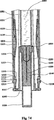
図1−図50を参照すると、10において本発明の例示的な実施例によって作られる自動インジェクタが示される。特に、インジェクタ10は、ハウジング100、シールド200、ドライバ300(図3)、カートリッジ500および駆動ユニット400(図3)を含む。後にさらに詳細に説明されるように、インジェクタ10の例は、好ましくはハウジング100から延在する板ばね131(図3)をも含む。本実施例において、シールド200はハウジング100上で摺動する。
Referring to FIGS. 1-50, at 10 an automatic injector made according to an exemplary embodiment of the present invention is shown. In particular, the
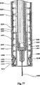
図1−図50を参照すると、30(図2)においてもまた、本発明の例示的な別の実施例によって作られる自動インジェクタが示され、シールド250がハウジング160内部で摺動する。特に、インジェクタ30は、ハウジング160、シールド250、ドライバ350、カートリッジ500および駆動ユニット450を含む。後にさらに詳細に説明されるように、好ましくはインジェクタ30の例も、シールド250から延在する板ばね285(図4)を含む。
Referring to FIGS. 1-50, also at 30 (FIG. 2), an automatic injector made in accordance with another exemplary embodiment of the present invention is shown, with the
図3に示されるように、ハウジング100はシールド200と接続されてカートリッジ500のための外装を形成する。外面的には、自動インジェクタ10は、図1に図示するように、ペン型円筒状構造を表す。インジェクタ10は、針が送達のためにそこから露出される遠端11と、遠端11の反対側の近端12とを有する。特定の理論に限られずに、遠位という用語は、送達のために注射部位に当てられるインジェクタの端部または方向を指し、近位という用語は遠端または遠位方向の反対側の端部または方向を指す。
ハウジング160内で摺動するシールド250を有する例示的な実施例において、ハウジング160は図4に示されるようにシールド250と接続され、カートリッジ500のための外装を形成する。外面的には、自動インジェクタ30は、図2に図示するように、ペン型円筒構造を表す。インジェクタ30は、針が送達のためにそこから露出される遠端31と、遠端31の反対側の近端32とを有する。特定の理論に限られずに、遠位という用語は、送達のために注射部位に当てられるインジェクタの端部または方向を指し、近位という用語は遠端または遠位方向の反対側の端部または方向を指す。両方の実施例10/30は、ハウジング上で摺動するシールドまたはハウジング内部で摺動するシールドのいずれかを用いて、基本機構を保持する。
As shown in FIG. 3, the
In an exemplary embodiment having a
ハウジング100上で摺動するシールド200を有する例示的な実施例10において、ハウジング100はフィンガ状延長部104を備える近位面を有する(図3)。これらの
延長部は、カートリッジ500のバレルのフランジ513を捕らえることを目的とするラッチ105および106を有する(図3参照)。さらに、ハウジング100およびシールド200は、ドライバ300および駆動手段400を収容する外装を形成する。例としてのみ図3および図5に図示したように、駆動手段はばね400を含み得る。ドライバ300は、ハウジング100とかみ合わされる間、その初期位置において維持される。ドライバ300は、圧縮ばね400によって予圧される。
In the
ハウジング160内部で摺動するシールド250を有する例示的な実施例30において、ハウジング160はフィンガ型延長部164(図4)を備える近端面を有する。これらの延長部は、カートリッジ500バレルのフランジ513を捕らえることを目的とするラッチ165および166を有する(図4参照)。さらに、ハウジング160およびシールド250は、ドライバ350および駆動手段450を収容する外装を形成する。好ましくは、図4に図示したように、駆動手段はばね450を含み得る。ドライバ350は、ハウジング160とかみ合わされる間、その初期位置において維持される。ドライバ350は圧縮ばね450によって予圧される。
In the
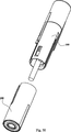
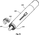
自動インジェクタの使用の最初のステップは、ハウジングの実施例上のシールドについて示された、針512の保護キャップ540(針カバー)の取外しである。キャップは1つの構成要素、例えば弾性保護キャップ541を含み得る。代替的に保護キャップ540は、第2の構成要素、例えば硬質のプラスチック保護キャップ542をさらに含み得る。針512の保護キャップ540は、自動インジェクタの遠端を通って突出する(図1および図2参照)。それは図6に示されるように、流路を開けるため、使用の第1のステップにおいてインジェクタから取外される。保護キャップ540はさらに、シールド200を使用前の偶発的な衝撃から保護する。
The first step in the use of the automatic injector is the removal of the protective cap 540 (needle cover) of the
例示的な実施例の自動インジェクタは、最小数の部品を有する。最小数の構成要素を達成するために、注射部位に向かってインジェクタを押しながら、針配備の初期ステップ(組織への針挿入)がユーザにより実現される。針の挿入は、自動的にドライバの解放をトリガして、注射を開始する。 The automatic injector of the exemplary embodiment has a minimum number of parts. To achieve the minimum number of components, the initial step of needle deployment (needle insertion into tissue) is realized by the user while pushing the injector towards the injection site. The insertion of the needle automatically triggers the release of the driver and starts the injection.
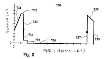
注射部位に向かってインジェクタを押す間のシールドの変位は、ハウジングからのドライバの係合解除を結果としてもたらす。シールド移動の初期部分のシールドの変位は、図7に示すように、短い距離での相当な力を必要とする。シールドを変位するのに必要な力700は、シールドの初期変位711により急増する。それは、移動712の初期セグメントの間高いままであって、次に短距離移動713の間急速に減少する。シールド変位力は、移動714の第2の部分にわたって低いままである。シールドが変位され、715において針が完全に挿入された後、ユーザにより自動インジェクタに与えられた力は0近くにまで低下する。
The displacement of the shield while pushing the injector toward the injection site results in disengagement of the driver from the housing. As shown in FIG. 7, the displacement of the shield at the initial part of the shield movement requires a considerable force at a short distance. The
短距離での大きな初期シールド変位力は、シールドが完全に変位され、針が人間の運動の慣性のために完全に挿入されることを保証する。自動インジェクタは、シールド移動の初期部分におけるシールド変位のために、ユーザに約1kgの力を要求する。 A large initial shield displacement force at short distances ensures that the shield is fully displaced and the needle is fully inserted due to the inertia of human movement. The automatic injector requires a user a force of about 1 kg due to shield displacement in the initial part of shield movement.
時間750の関数としてのシールド変位力のプロファイルが図8で示される。与えられた力731、732、733、734および735は、それぞれ変位711、712、713、714および715に対応する。
A profile of the shield displacement force as a function of
ドライバ300、ハウジング100およびシールド200は、上記に規定される力でハウジングからドライバを係合解除するのを容易にすることを目的とする、一組の特徴部を有する。自動インジェクタの動作は、自動インジェクタ構成要素および構成要素の相互作
用の詳細な説明から明らかになる。
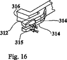
ハウジング上に摺動するシールドを有する本発明の例示的な実施例のドライバは、図9および図10にて示されるように、最初はハウジングに係合される。安定的な係合は、保管中または移送中に潜在的な衝撃によってばねが偶発的に解放されることを防ぐ。ユーザによるシールド変位の作用は、3段階で実行される。最初にシールドレール221は、ドライバフィンガパッド316に接線力を与えてこれらを合わせる。与えられた力の方向は、図15に矢印で示される。さらなる運動の間、シールドレール222は、ラッチフィンガパッド316を径方向に押す(図11参照)。この力の方向も図16に矢印で示される。ラッチフィンガ314は、径方向に曲がり、最後にはハウジング100からドライバ300を係合解除する。
The driver of the exemplary embodiment of the present invention having a shield that slides over the housing is initially engaged with the housing, as shown in FIGS. Stable engagement prevents accidental release of the spring due to potential impact during storage or transfer. The action of the shield displacement by the user is executed in three stages. First, the
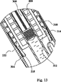
ハウジングに相対するドライバ運動が開始される。図12および図13に示されるように薬剤送達が開始する。この段階において、ラッチフィンガ314に与えられる接線力は実質的に低下する。フィンガ314のバレル511に向う曲がりが送達時間中持続する間、フィンガ314は無負荷の位置にまで広がる(図23)。
A driver movement relative to the housing is initiated. Drug delivery begins as shown in FIGS. At this stage, the tangential force applied to the
ドライバ300はハウジング内で摺動して位置する。ドライバ300がハウジング100から係合解除されるとき、インジェクタ10が作動される。ドライバはばね400によって付勢される。ばね400は、ドライバを自動インジェクタ11の遠端の方へ前方に摺動させる(図21)。ドライバ300は、バレル511を通ってストッパを動かし、バレルの流体を針512を通して注射部位に送達されるよう強制する。ドライバの中間位置は図22に示される。
The
ハウジング上で摺動するシールドを有する本発明の例示的な実施例のドライバ300(図14参照)は、ベース330、ドライバロッド320およびサイドフィンガ310から構成される。サイドフィンガ310は、ベース330に取付けられるコア311を有する。反対の端部では、フィンガ311はバレルを当接する突起312とハウジングに係合されたラッチ313とを有する。ラッチは突起部315を備える2つのラッチフィンガ314から構成される。これらの部分315は、オーバーハング部分316を有する。
The driver 300 (see FIG. 14) of the exemplary embodiment of the present invention having a shield that slides on the housing is comprised of a
ドライバがハウジングから係合解除されたあと、ラッチフィンガは図16に示されるように、径方向に偏向する。ラッチフィンガ314の偏向は、ドライバがハウジング内で摺動することを可能にする。
After the driver is disengaged from the housing, the latch fingers deflect radially as shown in FIG. The deflection of the
ハウジング100(図17および図18参照)は、2つの主要な領域を有する円筒状の部品である。2つの主要な領域とは、円筒状部分101と、シールド200の内周に一致する減じられた外周を有する第2の円筒状部分102とである。ハウジング100もベース103を有する。ベース103は、ラッチ105および106を有する2つフィンガ104を有する。ラッチ105および106は、組立後のカートリッジのバレルを捕らえて保持する。
The housing 100 (see FIGS. 17 and 18) is a cylindrical part having two main areas. The two main regions are a
ハウジング100は、長く狭い部分121および広い開口部122を有する2つの対称のスリット120を有する。広い開口部122は、ドライバをアセンブリのハウジングに係合するためのドライバラッチフィンガ314を受取る。応力を受けない状態のオーバーハング部分316は、ドライバをハウジングにさらに固定する開口部122より広い。
The
ハウジングは、組込式板ばね131を有する2つの対称開口部130を含む。これらの板ばねは、ベース132においてハウジング100に取付けられる。後述されるように、板ばねは送達完了後に遮蔽された位置でシールドを固定するよう機能する。
The housing includes two
自動インジェクタは、観察ウィンドウ800(図9参照)および長さが減じられた観察ウィンドウ820(図12参照)を有する。このウィンドウは、ハウジングの部分102に位置し、シールド200における一致するスロット225とともにハウジングスロット113により形成される。観察ウィンドウはユーザにバレルを露出する。増加した直径を有するハウジング領域111は、延長部112でシールドに延長してそれを囲み、インジェクタの動作中、ユーザに向上した保持能力および支持を与える。
The automatic injector has an observation window 800 (see FIG. 9) and an
ハウジングはさらに2つの平らな領域123を有する。これらの領域は内側シールド面上に突起を収容する。
The housing further has two
シールド200(図19および図20参照)は、円筒状部分201を有する円筒状部品である。その内周は部分102のハウジング100の外周に対応する。シールド200は、2つの外部平坦部202を有する。さらに、シールドはカートリッジ針を受取るために開口部205のあるベース204を有する。ベース204は、皮下部位との接続を向上させるための2つの突き出したリング状特徴部206および207を有する。
The shield 200 (see FIGS. 19 and 20) is a cylindrical part having a
シールドはさらに、内面上に2つの突き出した領域220を有する。これらはドライバのラッチフィンガのオーバーハング部分316を係合する外側フィンガ221を形成し、動作中は突出するラッチフィンガ314を共に押す。突き出した部分も中央フィンガ222を形成し、ハウジングからドライバを係合解除する。シールドラッチ223は装置の分解を防ぎ、カートリッジの遮蔽後の針の二次的な露出を防ぐ。
The shield further has two protruding
注射終了近くには、ドライバフィンガ311の突起312はバレル511から滑ってずれ、フィンガ311がカートリッジ500の直径が減じられたネック部Nの方へ偏向することを可能にする。図24に示されるように、この運動はばね400がラッチ313上を摺動してシールド204のベースを係合することを可能にする。同時にばね400は、図24に示されるように板ばね131を偏向させる。このように、これらの突起312は、ドライバ300のための「バレル直径変化」検出器を形成する。
Near the end of the injection, the
図25に示されるように、シールド204のベースに作用するばねは著しい力をもたらし、結果的にカートリッジ針を皮下組織から引き抜き、シールドをその伸長した位置に戻す。さらに、シールドのベースに影響を与えるばねは、薬剤送達の終了について明確な触覚的および聴覚的な表示を与える。
As shown in FIG. 25, the spring acting on the base of the
ばね400は、ハウジング100に外向きに取付けられる板ばね131を強制する。シールド223のラッチは板ばね131と相互作用し、それによりシールド200の変位が繰り返すのを防ぐ。自動インジェクタのシールド200は、リング状特徴部136によって、ハウジング100からずれることがさらに防止される。自動インジェクタは、ここで遮蔽された針を有し、処分の準備ができている。
The
ハウジング内部にシールドを有する例示的な別の実施例は、さらに図26から図36に記載される。ハウジング内部で摺動するシールドを有する本発明の例示的な実施例のドライバ350(図26参照)は、ベース380、ドライバロッド371およびサイドフィンガ360から構成される。サイドフィンガ360は、ベース380に取り付けられるコア361を有する。フィンガ361は、バレル511に当接する突起362およびハウジングに係合されるラッチ363を反対側の端部に有する。ラッチは、より低い2つのラッチ領域365および突き出した部分364から構成される。
Another exemplary embodiment having a shield inside the housing is further described in FIGS. The driver 350 (see FIG. 26) of the exemplary embodiment of the present invention having a shield that slides inside the housing is comprised of a
ハウジング/ドライバ係合解除機構は、この例示的な実施例では異なる。ラッチ363
は、後述されるようにハウジングおよびドライバの間で固定されるシールド250によって内向きに強制されるラジアル平面においてのみ偏向する。
The housing / driver disengagement mechanism is different in this exemplary embodiment.
Are deflected only in a radial plane that is forced inward by a
ハウジング160(図28および図29参照)は、2つの主要な領域を有する円筒状部品である。刻みのついた部分161および円筒状部分162である。内周181はシールド250の外周と一致する。ハウジング160もまたベース163を有する。ベース163は、ラッチ165および166を有する2つのフィンガ164を有する。ラッチ165および166は、組立後のカートリッジのバレルを捕らえ、保持する。
The housing 160 (see FIGS. 28 and 29) is a cylindrical part having two main regions. A notched
ハウジング160は、一対の対称のラッチ172を有する。これらのラッチは使用後にシールドと相互作用し、遮蔽された位置にロックする。ハウジングラッチ172は、送達後の装置の分解および針の二次的な露出を防ぐ。ラッチ173の他の対は、ドライバ350をハウジング160に解放可能に取付ける。
The
ハウジング160は、さらに一対の対称の開口部171を有する。これらの開口部はシールド250の開口部とともに観察ウィンドウを形成する。
The
シールド250(図30および図31参照)は、円筒状部分251を有する円筒状部品である。その外周はセクション162のハウジング160の内周と一致する。シールドは、組込式板ばね282を有する2つの対称開口部280を含む。これらの板ばねは、ベース282においてシールド250に取り付けられる。後述されるように、板ばねは送達完了後に遮蔽された位置でシールドを固定するよう機能する。さらに、シールドはカートリッジ針を受取るために開口部253のあるベース254を有する。ベース254は、皮下部位との接続を向上させるための2つの突き出したリング状特徴部256および257を有する。
The shield 250 (see FIGS. 30 and 31) is a cylindrical part having a
シールドはさらに、2つの細長い開口部270を有する。これらは、ハウジング開口部171と連関して観察ウィンドウを形成する。シールドはさらに、リブ291を有する。これらのリブはばね450を支持する。
The shield further has two
シールド250は、対称のスリット271を有する。これらのスリットは、広い部分272とその後により狭い部分273とを有する。より狭い部分の正面はテーパ状の274である。図32から図35に示されるように、シールドのこのテーパ274は、作動中ハウジングからドライバを係合解除する。
The
ドライバ350およびハウジング250の係合解除プロセスの始まりは、図32および図33に示される。ドライバラッチ363の延長部364はハウジングピン173に係合される。シールド係合解除テーパ274はラッチ365およびハウジング160の間に押込まれる。最終的に、図34および図35に示されるように、ドライバラッチ364が偏向されてハウジングから係合解除される。
The beginning of the disengagement process for
ハウジング内部にシールドを有する実施例の自動化された遮蔽プロセスの動作は、ハウジング上にシールドを有する場合の動作と同様である。図36に示されるように、シールド254のベースに作用するばね450は著しい力をもたらし、結果的にカートリッジ針を皮下組織から引き抜き、シールドをその伸長された位置に戻す。
The operation of the automated shielding process of the embodiment having a shield inside the housing is similar to the operation with the shield on the housing. As shown in FIG. 36, the
典型的なハイパック(Hypak)(登録商標)カートリッジ500が図37に示される。それは固定された針512を有するガラスのバレル511から構成されるバレル510を有する。ガラスのバレル511はフランジ513を有する。バレルは薬剤530で満たされる。薬剤はバレルと摺動関係にあるストッパ520によって密封される。針は、弾
性構成要素541からできた、針に当接する保護キャップ540により遮蔽される。針保護カバー540はしばしば、キャップの取外しを簡単にする硬質のプラスチック保護カップ542を有する。
A typical
滴定する装置
滴定は、観察ウィンドウによって実現可能となる。カートリッジが観察される場合にのみ、ユーザはカートリッジの中身を滴定し、空気を放出することができる。滴定を実行するための3つの例は、図41、図42および図43において詳述される。
Titration device Titration can be achieved by an observation window. Only when the cartridge is observed can the user titrate the cartridge contents and release air. Three examples for performing titration are detailed in FIGS. 41, 42 and 43.
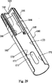
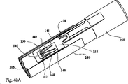
ハウジング上に摺動するシールドを有する本発明の例示的な実施例のインジェクタ20は、図41に示されるように、インジェクタの近端においてハウジングのベースの開口部197を通じて突出するロッド600を含む。ドライバ325は、滴定ロッド600を収容するための内部ロッド通路322を有する。滴定ロッドは、ハウジングの開口部197のハウジングのねじ切り部198と係合されるねじ切り部610を有する。ロッドはまた、ストッパ520に当接するねじ切りのない部分620および手動操作のための刻みのあるノブ630を有する。
The
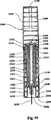
図42のねじ切り部のないロッドは、ねじ切られた滴定ロッドの代替である。ロッド601は、インジェクタ21の近端において後部壁193の開口部199を通って延在する。ロッド601は、滴定中にストッパ520を押すためにストッパに当接する、ねじ切りのない部分621を有する。
The unthreaded rod of FIG. 42 is an alternative to the threaded titration rod. The
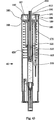
別の代替は、ツメを有する(ratcheted)表面を有する滴定ロッドである。ハウジング上に摺動するシールドを有する本発明の例示的な実施例のインジェクタ40は、図43に示されるように、インジェクタの近端においてハウジングのベースの開口部192を通じて突出するロッド602を含む。ドライバ375は、滴定ロッド602を収容するための内部325が中空のロッド322を有する。滴定ロッドは、ツメ部187とハウジング185のノーバックラッチ(no-back latch)186に係合される鋸歯状部分612を有する。ロッド602も、ストッパ520に作用するツメのない部分622を有する。ツメのある機構はハウジング185の一部として形成される。それはハウジングを係合する歯部189を有するヒンジ191において固定される。ツメ部187の移動は、リミッタ180により制限される。ツメ部を用いる滴定機構は、ロッドのストッパに向っての増分的な推進を可能にする。
Another alternative is a titration rod with a ratcheted surface. The
装置の使用
図6の好ましい実施例に示されるように、インジェクタ10の使用における第1のステップは、安全キャップ540を取外すことである。次に自動インジェクタ10が注射部位に当てられ、ハウジング100上を押すことによって押圧される。この作用は結果的に針512の露出および挿入をもたらす。これはまた、自動的に注射を始めるドライバ300を解放する。
Use of the Device As shown in the preferred embodiment of FIG. 6, the first step in the use of the
注射時間中、保持力は図8の素子736に示すように最小である。注射完了後、ばね400はシールド200の方へ動く。図7および図8においてそれぞれ721および737で示されるように、シールドに作用する力がばね力のレベルにまで増大する。この力が、組織からの針の引き抜き、およびシールド200による針の遮蔽に導く。ばね力は運動中いくらか減少する(変位722および力738参照)。遮蔽終了後、シールドはロックされる。インジェクタは処分の準備ができている。
During the injection time, the holding force is minimal as shown by element 736 in FIG. After the injection is complete, the
特定の理論に限られず、例えばインジェクタに働く作用する力の釣り合いの例としては、通常、シールド200を5mm程度変位するために約1.0kgf(10ニュートン)
を要する。例えば、駆動ユニット400の最初の注射力は約1.5kgf(15ニュートン)であり、遮蔽中の最終の押込力は約1kgfである。例えば、動的摩擦は最大で0.2kgf(2ニュートン)を要する。
Without being limited to a specific theory, for example, as an example of a balance of acting forces acting on an injector, about 1.0 kgf (10 Newtons) is usually used to displace the
Cost. For example, the initial injection force of the
板ばね131は、送達前または送達中にインジェクタ10の動作に影響を及ぼさない。しかしながら、後退中、ばね400は板ばね131を回避し、それを偏向する。シールド200は板ばね131およびラッチ223の間でロックされ、シールドの潜在的な軸方向運動およびその結果としての針512の再露出を防ぐ。換言すれば、シールド200はハウジング100にロックされて動くことができない。
The
滴定を有する装置の使用
このインジェクタ20(または21もしくは40)を使用する第1のステップは、インジェクタの遠端において開口部205から安全キャップ542を取外すことである。次にカートリッジ500のいかなる残気も取除かれ、シリンジ内の液体量は滴定によって必要な投与量に調整され得る。滴定は、針512が直立するようインジェクタ10を垂直に位置決めすることにより、かつ、滴定ロッド600(または601もしくは602)をストッパの方へ動かし、したがって針を通してインジェクタから不要な空気および薬剤を出すことにより、達成される。
Using a device with titration The first step in using this injector 20 (or 21 or 40) is to remove the
滴定は、充填技術の副産物である、予め充填されたシリンジに一般に含まれる残気を取り除くという課題を解決する。滴定はまた、長期間にわたる不動性(例えば保管)によってストッパ520とバレル511との間に生じる、潜在的な高い静止摩擦を解放する。
Titration solves the problem of removing residual air typically contained in pre-filled syringes, a by-product of the filling technique. Titration also releases potential high static friction that occurs between
滴定中にインジェクタ内部で集められる薬剤の量を最小にするために、残気が除去されたあと、ウィンドウで観察される間にインジェクタは針を下に向けることができる。 In order to minimize the amount of drug collected inside the injector during titration, the injector can point the needle down while it is observed in the window after residual air is removed.
ハウジング上で摺動するシールドを有する本発明の例示的な実施例のハウジング100およびシールド200は、好ましくは、ユーザが送達前後および送達中に、カートリッジ500の中身および投与量を見ることを可能にするウィンドウを含む。このウィンドウはまた、滴定に不可欠である。図9および図12はインジェクタ10の等角図である。図9は、注射前および滴定中の段階におけるインジェクタ10に対応する。注射準備の間、バレルの中身を観察するために完全なウィンドウを有することが重要である。図12は、観察ウィンドウのサイズがかなり低下した場合の注射中のインジェクタ10を示す。この段階で薬剤は観察されない。送達後、インジェクタ10の観察ウィンドウ800は再び元の長さになり、検査のため、空のカートリッジおよびばねがウィンドウを通して見える。
The
要するに、インジェクタ10のウィンドウ800を通して見ているユーザは、カートリッジ500の投与量を観察することができる。保管中、カートリッジ500は薬液で満たされる。滴定中、余分の溶液および気泡はバレル500から押し出される。
In short, a user looking through the
ハウジング内部で摺動するシールドを有する本発明の例示的な実施例のインジェクタ30は、図4に示されるように、注射中も完全なサイズの観察ウィンドウを有する。ハウジング160の開口部171は、活性なカートリッジ領域の長さと一致する。シールド250の開口部270は著しく長いので、注射前後および注射中に、一定したカートリッジの可視性をもたらす。
The
例示的な実施例によって構成されるインジェクタは、患者に薬剤を送達するのに安全で有効な処理法を提供する。インジェクタは使い捨て装置として用いられ、本願明細書において記載される特徴のさまざまな結合を組み入れることができる。 An injector constructed according to an exemplary embodiment provides a safe and effective treatment method for delivering medication to a patient. The injector is used as a disposable device and can incorporate various combinations of the features described herein.
代替的実施例
本発明の代替的実施例は、ハウジングに摺動するシールドを有する本発明の例示的な実施例の図40A、図40Bおよび図40Cに示されるように、異なるラッチ機構を有し得る。ハウジングの切欠部はパターンを形成し、パターンは処分のためシールドのロックをもたらし、かつ第2のシールド変位を防ぐ。
Alternative Embodiments An alternative embodiment of the present invention has a different latching mechanism as shown in FIGS. 40A, 40B and 40C of an exemplary embodiment of the present invention having a shield that slides into the housing. obtain. The notch in the housing forms a pattern, which provides a shield lock for disposal and prevents a second shield displacement.
シールド240は、スロット付きハウジング150と相互作用する2つのピン233を有する。ハウジングの切欠部は図40Aに示され、140から147までの番号により定義される。ハウジング150は、2つの切欠部140を含む。切欠部140は成形されたラッチ141を生成する。ラッチ141は、ベース144においてハウジング部152に取り付けられる。ラッチ141は、143により接続される2つの部分142および147から形成される。ラッチ141はギャップ145によって分離される。
The
図40Aは、この代替的ラッチ機構の動作を示す。明確にするため、ハウジング150およびシールド240のみが示される。さらに、シールド240の部分およびハウジング150は取除かれる。図40Aは変位前のアセンブリを示す。図40Bは変位されたシールドを示す。図40Cは廃棄位置を示す。注射部位に対してシールド240を押し付けることは、ラッチ142の曲がりおよび空気ギャップ145の閉鎖を引き起こす。シールド240の端部において変位ラッチ142が解放され、図40Bに示されるようにその元来の形状に戻る。一旦送達が完了すると、ばね400の作用がシールド240を強制して後退させる。ピン233は、ラッチ142間のギャップの中に動いて、曲がるラッチ要素142および147によって、空気ギャップ145を拡張する。図40Cに示されるように、ピン233はその最終位置に到達する。これらのピン233は針の再露出を防ぐ。ラッチ121の突起146は、ハウジング150およびシールド240によって与えられた保持力をさらに増加させる。
FIG. 40A illustrates the operation of this alternative latch mechanism. For clarity, only
要するに、シールド240の変位前に、ピン233はハウジング内の切欠部により形成されるフック142内部に位置する(図40A参照)。シールド240の変位中、フックは偏向し、ピン233がハウジング切欠部140内部で軸方向に図40Bにおいて示される位置まで動くことを可能にする。シールド240が戻る間、ピン233はフック142を偏向し、フックのベースで終了する。フック突出部146は、フックおよびピンのロック機能をさらに助ける。
In short, before the
本発明の代替的実施例は、図44に示されるように、異なるカートリッジを有し得る。カートリッジのバレル510はフランジを欠いている。フランジ514がカートリッジアセンブリに加えられる。
Alternative embodiments of the invention may have different cartridges, as shown in FIG. The
本発明の別の代替的実施例は、図45に示されるように、異なるカートリッジを有し得る。カートリッジのバレル510はフランジを欠いている。フランジ514がカートリッジアセンブリに加えられる。さらに針が作動される(滴定および薬剤送達のためにストッパ522を突き刺すよう押される)。
Another alternative embodiment of the present invention may have a different cartridge, as shown in FIG. The
例示的な実施例は、針が露出される遠端および遠端の反対側の近端を有する各インジェクタを示す。例示的な実施例において、インジェクタはユーザの助けをもって針を配備し、カートリッジに薬剤を送達し、針を遮蔽する。好ましくは、インジェクタは明確な送達終了表示(例えば「クリックタイプ」の効果および関連付けられる触覚的フィードバック)を与える。インジェクタはカートリッジのまわりで組立てられ得る。いくつかの典型的な実施例のさらなる特徴として、カートリッジはストッパを含み、ストッパは滴定のために、ロッド、ねじ切りバックロッドまたはツメを有するロッドによってシリンジバレル内で動かされ得る。ロッドは滴定のために一方向にのみ動かされ得る。ロッドはストッパま
たはドライバに接続しておらず、妨げられずに送達を可能にする。
The illustrative example shows each injector having a far end where the needle is exposed and a proximal end opposite the far end. In an exemplary embodiment, the injector deploys the needle with the help of the user, delivers the drug to the cartridge, and shields the needle. Preferably, the injector provides a clear end-of-delivery indication (eg, “click type” effect and associated haptic feedback). The injector can be assembled around the cartridge. As a further feature of some exemplary embodiments, the cartridge includes a stopper that can be moved within the syringe barrel by a rod, a threaded back rod or a rod with a claw for titration. The rod can only be moved in one direction for titration. The rod is not connected to a stopper or driver and allows unobstructed delivery.
インジェクタは、針の潜在的な露出を最小にするためにさまざまな安全機能を与える。これらの機能は誤動作防止機構を含む。特に、安全リング900が図46および図47において示され、この機能を与える。リング900は、自動インジェクタの作動を防ぐ。リングが取外された後にのみ作動が可能である。
The injector provides various safety features to minimize the potential exposure of the needle. These functions include a malfunction prevention mechanism. In particular, a
代替的には、使用の最初にシールドを動かすための大きな力は、シールドの変位が早まるのを防ぐ。さらに、針−ロック機構が使用後の針をロックする。インジェクタは、衝撃および騒音の低減のために任意で制振材料(例えばブシュ、緩衝タブ)を含む。インジェクタは、好ましくは拡張ばねの形で、低弾性定数ばねを用いて線形の速度制御を提供する。拡張ばねは長くすることができ、そのためカートリッジストッパがばねの長さと比較して小さい縦方向範囲にわたって動き、それによりその小さい範囲を通じてばねの力を一定にすることができる。 Alternatively, the large force to move the shield at the beginning of use prevents premature displacement of the shield. Furthermore, the needle-lock mechanism locks the used needle. The injector optionally includes damping material (e.g. bushings, buffer tabs) for impact and noise reduction. The injector provides linear speed control using a low elastic constant spring, preferably in the form of an expansion spring. The expansion spring can be lengthened so that the cartridge stopper can move over a small longitudinal range compared to the length of the spring, thereby keeping the spring force constant throughout the small range.
例示的な実施例の送達装置は、噴射される複合物量の正確な滴定および測定を可能にする。さらに、送達終了が明らかなので、送達終了の表示のためのアイコンタクトの必要はなく、したがって、ユーザが観察ウィンドウを見ることができない場合の送達が容易になる。 The delivery device of the exemplary embodiment allows for accurate titration and measurement of the amount of composite ejected. Furthermore, since the end of delivery is obvious, there is no need for eye contact to indicate the end of delivery, thus facilitating delivery when the user cannot see the observation window.
当業者が容易に理解するように、流体の薬剤の送達は、駆動ユニットまたはばねのみによっては決定されない。それはさらに、流体の物性および流体の経路配置に依存する。したがって、送達曲線は、ばねの反応曲線と同一ではない。流体は液圧ダンパとして作用し、流れに対するその抵抗は流れに与えられる力に関連する。 As one skilled in the art will readily appreciate, delivery of fluid medication is not determined solely by the drive unit or spring. It further depends on the physical properties of the fluid and the fluid path arrangement. Thus, the delivery curve is not identical to the spring response curve. The fluid acts as a hydraulic damper and its resistance to flow is related to the force applied to the flow.
例示的な実施例の駆動ユニットは、ばねであり得る。好ましくは圧縮ばねは、実質的に対称なハウジング断面を有する実施例において用いられる。コイルに必要とされる運動範囲および重なり合った厚さは、この初期圧縮を制限する。 The drive unit of the exemplary embodiment can be a spring. Preferably, the compression spring is used in embodiments having a substantially symmetrical housing cross section. The range of motion required for the coil and the overlapping thickness limit this initial compression.
駆動ばねは最も入手しやすい送達制御要素である。ばねがもたらす主要な特徴は低弾性定数である。低定数は、より一様な送達プロファイル、送達継続時間の制御におけるより高い柔軟性、および保管期間中のばね荷重の低減をもたらし、注射サイクル終了時に十分な力を与える。長いばねを使用することは、ばねの弾性定数を変えることおよび予圧を可能にすることによって、送達時間制御およびプロファイルを向上させる利点をもたらす。 The drive spring is the most accessible delivery control element. The main feature provided by the spring is the low elastic constant. A low constant results in a more uniform delivery profile, greater flexibility in controlling delivery duration, and reduced spring loading during storage, providing sufficient force at the end of the injection cycle. Using a long spring provides the advantage of improving delivery time control and profile by changing the spring's elastic constant and allowing preload.
さらに本発明は、従来技術に関する他の課題を解決する。例えば、ドライバおよびばねは、針恐怖症および針での負傷の課題を解決する。加えてインジェクタは、患者が自動注射システムを介して投与量を測定し自己投与することを可能にする滴定の利点を与えるロッドを含み、ロッドは送達前に自動的にストッパから分離する。ロッドを有するインジェクタによってさらに、ユーザがシステム内の残留薬剤を最小にすること、および、他の場合には使用前に自動システムに封じ込められ得る気泡をなくすことが可能になる。さらにウィンドウは、使用前にユーザが投与量の調合を見、使用後には薬剤が送達されたことを知ることを可能にする。 Furthermore, the present invention solves other problems related to the prior art. For example, drivers and springs solve the problem of needle phobia and needle injury. In addition, the injector includes a rod that provides a titration advantage that allows the patient to measure and self-administer dose via an automatic injection system, the rod automatically separating from the stopper prior to delivery. Injectors with rods further allow the user to minimize residual medication in the system and eliminate air bubbles that could otherwise be trapped in the automated system prior to use. In addition, the window allows the user to see the dosage formulation before use and know that the drug has been delivered after use.
本出願の概念が、本願明細書に開示される例示的な実施例を含む種々の好ましい実施例に容易に適用され得ることは、上述の説明および添付の図面から明らかであろう。例えば、当業者が容易に理解するように、弾性「O」リングまたは圧縮ガスなどの他の駆動ユニットおよび後退ユニットが、本願明細書に開示される圧縮ばねの代わりに、ドライバを付勢するために用いられ得る。 It will be apparent from the foregoing description and accompanying drawings that the concepts of the present application may be readily applied to various preferred embodiments, including the exemplary embodiments disclosed herein. For example, as those skilled in the art will readily appreciate, other drive units and retraction units such as elastic “O” rings or compressed gas may bias the driver in place of the compression springs disclosed herein. Can be used.
例示的な実施例のための組立プロセスは、図48から図50に示される。最初のステップはドライバ300を有するカートリッジ500の組立を含む。ばね400はハウジング100に組立てられる。ドライバ/カートリッジサブアセンブリは、ハウジング/ばねサブアセンブリに併合される。シールドを加えることで自動インジェクタが完成する。構成要素が少数なので、組立プロセスは簡単である。
The assembly process for the exemplary embodiment is shown in FIGS. The first step involves assembling the
ここで図51−図81に関連して、本発明のさらなる例示的な実施例に従って構成される自動インジェクタが1001に示される。特に、インジェクタ1001はハウジング1100、シールド1200、ドライバ1300、カートリッジ1500および駆動ユニット1400を含む。図52に示されるように、ハウジング1100はシールド1200と接続され、カートリッジ1500のための格納外装を形成する。図51に示されるように、外面的には自動インジェクタはペン型の円筒状構造を示す。インジェクタ1001は、針が送達のためにそこから露出される遠端1206と遠端1206の反対側の近端1101とを有する。
51-81, an automatic injector configured in accordance with a further exemplary embodiment of the present invention is shown at 1001. In particular, the injector 1001 includes a
格納位置におけるアセンブリが図52および図53に示される。ハウジング1100およびシールド1200は、ドライバ1300および駆動手段1400を収容する外装を形成する。駆動手段は、図52および図53に示されるように、従来はばね400である。ドライバは、ハウジングとのかみ合いを介して初期位置に維持される。ドライバは圧縮ばね1400によって予圧される。
The assembly in the retracted position is shown in FIGS. The
カートリッジ1500はハウジング内部に位置決めされる。それは、インジェクタの遠端に向う運動から径方向および軸方向にずれないように、ドライバ1300によって支持される。内部ハウジングアーム1130の縁部1132は、近端方向におけるカートリッジの軸上の運動を防ぐ。カートリッジは、バレルフランジ1520とカートリッジ従動子1330との接続を介してドライバ1300により保持され、従動子はバレルの外側およびバレルフランジ1520に接触する。
The
自動インジェクタの使用における第1のステップは、実施例で示される針1530の針カバーアセンブリ1570の取外しである。針カバーアセンブリ1570は1つの構成要素、弾性保護カップ1540から構成され得る。代替的には、保護カバーアセンブリはまた、第2の構成要素である硬質プラスチック保護部1550を含み得る。針1530の針カバーアセンブリ1570は、自動インジェクタの遠端を通じて突出する(図51、図52および図53参照)。それは使用前にインジェクタから取外される。保護針カバーアセンブリ1570はさらに、誤動作を予防するため、自動インジェクタ使用前のシールド1200の偶発的な衝撃を防ぐ。
The first step in the use of the automatic injector is removal of the
ドライバ1300、ハウジング1100およびシールド1200は、格納中は係合を容易にするよう、かつ作動中は下記に規定される力でハウジングからのドライバの係合解除を容易にするよう意図された、一組の特徴部を有する。自動インジェクタの動作は、自動インジェクタ構成要素および構成要素の相互作用の下記の詳細な説明から明らかになる。
The
本発明の例示的な実施例のドライバは、図53に示されるように、最初はハウジングに係合される。固定的な係合は、保管中または移送中の駆動ばねの偶発的な解放を防ぐ。 The driver of the exemplary embodiment of the present invention is initially engaged with the housing, as shown in FIG. The fixed engagement prevents accidental release of the drive spring during storage or transfer.
ユーザによるシールド変位作用は、2つのステージにおいて実行される。ユーザは最初、最小の変位で著しい力を与える。しきい値力は、シールド1200およびハウジング1100の間の2つの相互作用領域により制御される。第1の相互作用は図52および図54に示され、図74および図75にさらに詳細に示される。シールド1200はロックフック1210を有する。フック1210は狭い断面1211において曲がることができる
。シールド1205のベースが注射部位に押しつけられると、シールドフック1214の前部傾斜部は、格納スリット1111の内縁部1114によって定位置に保たれる。最初に軸方向の力が最小の変位を伴って生成される。シールドフック1210が1211で曲がり始めると初めて、表面1214が1114上で摺動する。
The shield displacement action by the user is performed in two stages. The user initially applies a significant force with minimal displacement. The threshold force is controlled by two interaction areas between the
ユーザによって与えられる力がそれ以上増加すると第2のステージに至る。
第2のステージにおいて、図53および図55に示され、図70、図71、図72および図73においてさらに詳細に説明されるように、ドライバはシールドによってハウジングから係合解除される。力が増加すると、ハウジングに対するシールド変位の増加を生じる。格納中、前縁部1341はハウジングラッチ1107の縁部に乗る。シールド1200の前縁1242は、ハウジング格納ラッチ1105を偏向してドライバ1300を解放する。格納ラッチ1105は、観察ウィンドウ1110の機能の継続をもたらすスリット1106をも含む。
If the force applied by the user further increases, the second stage is reached.
In the second stage, as shown in FIGS. 53 and 55 and described in further detail in FIGS. 70, 71, 72 and 73, the driver is disengaged from the housing by the shield. Increasing the force results in an increase in shield displacement relative to the housing. During storage, the leading
シールド1200は、ドライバカム1340を案内するためにさらに長手方向スリット1241を有する。シールド1200の前縁1242は、スリット1241の両側に位置決めされる。したがって、格納ラッチ1105の径方向の偏向は、ドライバ突起1343およびドライバ1300の遠位への運動にいかなる干渉もなく、ドライバ機能1342を解放する。1105が偏向され、ドライバが解放された後、保持フック1210が送達スロット1112を係合するので、装置を送達位置に維持するのに力を必要としない。
The
図70は、格納中のハウジングおよびドライバかみ合いの部分的断面図を示す。図72は図70のラッチを通じた断面を示す。図71および図73は、インジェクタがトリガされた後の図70および図72に対応する。格納中、格納ラッチ1105は軸上のばね力を保持するが、トリガを可能にするよう軟質かつ可撓性である。ラッチ1105は、装置が注射部位から取除かれるまで、図55および図73に示されるように偏向された位置に留まる。
FIG. 70 shows a partial cross-sectional view of the housing and driver engagement during storage. 72 shows a cross section through the latch of FIG. 71 and 73 correspond to FIGS. 70 and 72 after the injector has been triggered. During storage, the
一旦ドライバ1300の突起1343がラッチ1105によって支持されなくなると、駆動機構1400はドライバ1300を前方に動かす。ドライバ1300の駆動板1312は、カートリッジ1500のストッパ1510を押す。カートリッジ1500は干渉なく前方へ動き、針1530を組織に突き刺す。
Once the
カートリッジ1500は3つの力成分を受ける。組織への針挿入、カートリッジからハウジングへの摩擦およびストッパからバレルへの摩擦である。注射カニューレ1530の挿入力は低く、数十grf(重量グラム)の範囲である。ストッパ1510およびガラスバレル1501の間の静止摩擦は可変であるが、ほとんどの場合、針の突き刺しへの抵抗より実質的に高い。カートリッジからハウジングへの摩擦は低い。別の要因は、カニューレ1530を通じた薬剤経路の液圧インピーダンスである。注射のため駆動機構1400により与えられる典型的な力は、100grfを超える。針挿入およびハウジング力に対するカートリッジ摩擦のために必要とされる力は比較的低く、薬剤送達開始前に完全な針の突き刺しを確実にする。
The
図56および図57は完全に突き刺した針を示す。カートリッジフランジ1520の遠位フランジ側1522が中央シールド突起1230の縁部1231に届くと、組織への針の突き刺しは停止する。駆動機構により与えられる力はストッパ1510上のドライバ1300に作用して薬剤を組織に押し込む。ドライバは、カートリッジが空になるまで、薬剤送達をしながらストッパと共に動いている。
56 and 57 show a fully pierced needle. When the
図58および図59は送達終了後の装置を示す。カートリッジ従動子1340はバレル
1503の端部から滑ってずれる。アーム1322の前部部分は内向きに偏向してばね1400を解放する。一旦ばね1400が解放されると、それはドライバ1300を回避する。この位置においてドライバは、それ以上のドライバ移動を遮断するハウジングアーム1130の送達支持部1134によって止められる。ドライバはカートリッジを保持する。ばね1400はドライバを回避し、ニーポイント1222の廃棄ラッチ1220上に径方向に外向きの力を与える。一旦1220が押しのけられると、縁部1221がハウジング1100の内径に触れるまで、僅かに拡張する。
58 and 59 show the device after delivery is complete.
ドライバ突起1343を回避した後、ドライバばね1400は、シールドロックフック1210の外面1212にぶつかる。フック1212上のばね1400の衝撃ポイントからフックラッチの回転軸ポイント1211までの径方向距離は、ロックフック1210を内向きに曲げる回転モーメントを生成する。フック1210の曲がりは、送達スリット1112からフック1210のラッチを外す。シールド1200はばねの力の下で遠位方向に自由に摺動する。フック1210上のばねの圧力の結果、注射部位でインジェクタを保持するユーザが感知する力が急増する。シールドに作用する増加した力は、送達終了時にユーザに対して触覚的な表示を与え、シールドを動かして遮蔽を完了し、シールドのロック機構を作動する。
After avoiding the
図60および図61は廃棄位置にある装置を示す。装置がシールドに与えられるばねの力に援助されながら注射部位から取り除かれた後、廃棄位置に達する。注射部位からの除去は、組織からの針の引き抜き、および、図62に示されるように、シールド1200による針の完全な遮蔽に至る。廃棄ロックは、廃棄ラッチ1220に接触する突起1220によって与えられる。針の再露出は突起1120により防がれる。ばね1400はラッチ1220が突起1120を回避するために後方に曲がることを可能にする一方で、ラッチ1220上に径方向の力を与える。ラッチプロファイルは、径方向において可撓性を保ちつつ、ラッチを硬質にして軸方向の力を保持することができるようにする。
60 and 61 show the device in the disposal position. The disposal position is reached after the device has been removed from the injection site with the help of the spring force applied to the shield. Removal from the injection site leads to withdrawal of the needle from the tissue and complete shielding of the needle by
システムに作用する力は、図62および図63に詳細に説明される。注射部位に向って自動インジェクタを押す間のシールドの変位は、ハウジングからのドライバの係合解除を結果としてもたらす。シールドの変位は、図62に示されるように、短距離において著しい力を必要とする。シールドの変位を開始するのに必要な力は、1710によって示されるように、事実上全く変位なく急増する。力のさらなる増加によりシールドの最初の変位1711に至る。近位方向におけるシールドの最大変位は、1712において達せられる。この位置は図54に示される。この時点で、シールドがスリット1112を係合するフック1210とハウジングを新たな位置において係合する一方で、ドライバはハウジングから係合解除する。インジェクタを注射部位に維持するのに必要な力は、短い移動距離1713の間事実上ゼロにまで下がる。送達終了が達成されるまで、シールド力は注射中ゼロ近くに留まる。
The forces acting on the system are described in detail in FIGS. 62 and 63. The displacement of the shield while pushing the autoinjector towards the injection site results in disengagement of the driver from the housing. Shield displacement requires significant force at short distances, as shown in FIG. The force required to initiate the displacement of the shield increases rapidly with virtually no displacement, as indicated by 1710. A further increase in force leads to the
短距離での最初のシールド変位力は高く、シールドが完全に変位されるることを保証し、装置は人間の運動の慣性によって有効にトリガされる。自動インジェクタは偶発的なトリガを防ぎ、装置の有効なトリガを確実にするために、シールド変位に十分な力をユーザに要求する。 The initial shield displacement force at short distances is high, ensuring that the shield is fully displaced and the device is effectively triggered by the inertia of human movement. The automatic injector requires the user sufficient force for shield displacement to prevent accidental triggering and ensure effective triggering of the device.
送達終了が達成された後、1722で示されるように、ユーザは、シールド遠位運動による針の引き抜きおよび遮蔽が生じる原因となる、突然の力の増加1721を経験する。廃棄されるときの装置の全長は格納時より長い。これは、トリガ位置を超える遠位のシールド伸長による。シールドが伸長されて廃棄のためにハウジングにロックされた後、シールド力は図62の1723に示されるように0にまで下がる。
After the end of delivery is achieved, as shown at 1722, the user experiences a
時間1750の関数としてのシールド変位力のプロファイルは図63に示される。作動および遮蔽は比較的短時間しかかからない。注射時間は1734に示されるように比較的長い。素子1730、1731、1732、1733、1736、1737および1738は、それぞれ図62の1711、1712、1713、1714、1721、1722および1723に対応する。
The shield displacement force profile as a function of
例示的な実施例の自動インジェクタは、最小限の部品の個数を有する。ハウジング1100は図64に詳述するインジェクタの主要な構造部品である。ハウジング1100は、ベース1109に取付けられる円筒状部分1108を有する。内部アーム1130はハウジングベース1109に取付けられる。円筒状部分1108は、格納ラッチ1105および観察ウィンドウ1110を含む。円筒状部分1108は、シールド1200との接続に用いられるロックスリット1111、1112、および廃棄ロックのために用いられるロック突起1120を含む。円筒ハウジング部分1108およびベース1109は、成形に際して助けとなるよう開口部1136を有する。さらにベースは、格納中ドライバ1300を支持するために、中央開口部1138を有する。
The automatic injector of the exemplary embodiment has a minimum number of parts. The
図65および図66に示されるように、シールド1200は、ベース1201によって接続される2つの同心の円筒状構造1240および1230から構成される。ベース1201は、内側1204および外側1205を有する。インジェクタベース1205の外面は、装置の使用中、注射部位に対して押付けられる。ベース表面1205は、注射部位との接続を向上させるための2つの突き出したリング状部分1207および1208を有する。
As shown in FIGS. 65 and 66, the
内部シリンダ1230の内径1234は、動作中、カートリッジ1500を案内する。内部シリンダ1230の縁部1231は、針1530が組織に突き刺している間、インジェクタ動作の開始中に前方へ進みながらカートリッジフランジに接触している。シールドの外部シリンダ1230はハウジング1100内部で摺動する。シールド1200は、廃棄ラッチ1220およびロックフック1210を含む。外側シリンダ1202のスリット1241は、ドライバ1300のためのガイドトラックとして作用する。内部シリンダ1230は一致するスリット1232を有する。スリット1241および1232は、ハウジング1110の開口部とともに、使用前に薬剤を観察することを可能にする。内部シリンダのスリット1223は、廃棄ラッチのスリット1223およびハウジングのスリット1113とともに、装置が廃棄位置にあるとき、送達終了時にピストンの状態を観察することを可能にする。
The
ドライバ1300は図67および図68に詳細に説明される。ドライバ1300は、ベース1350により接続される2つのサイドアーム1320を有するドライバロッド1305を有する。アーム1320は、前部部分1322および後部部分1321を有する。アームは、突起1343およびカートリッジ1500の外面に寄るカートリッジ従動子1330および1340を有する。さらに、突起1343は駆動手段と相互作用する傾斜面1342および前面1341を有する。サイドアームはアームの曲がりの助けになるようアンダカット1335をさらに有する。ドライバロッド1305は、チャネル状構造1310および前板1312を有する。チャネル1310は近端1311を有する。突起1352の外面はハウジング開口部と接続する。支持点1330に対して傾斜面1342に与えられる力のために、駆動手段により回転モーメントが生成される。アンダカット1335は軸として用いられる狭い部分を与え、カム1340がカートリッジによってもはや支持されなくなると前アームが曲がることを可能にする。ストッパ1510が送達終了に近づくとカム1340は曲がることができ、駆動機械1400がドライバを回避することを可能にする。
The
典型的なカートリッジ1500が図69に示される。それは固定された針1530を伴うガラスバレル1501を有する。ガラスバレル1501はフランジ1520を有する。バレルは薬剤1560で満たされる。薬剤は、バレルと摺動関係にあるストッパ1510によって密封される。針は、針に当接している弾性針無菌カバーからできた保護カバー1540により遮蔽される。針保護カバー1540は、カバーの取外しを単純化し得る針カバーアセンブリ1570を形成する1540と共に、しばしば硬質のプラスチック保護部1550を有する。代替的に、カートリッジは(カープジェクト(Carpuject)(登録商標)におけるような)二面針を有し得る。針は、カートリッジを作動し、薬剤送達のためにゴムのストッパを通じた針の近端の突き刺しを生じるよう、動作の初めに軸方向の力を必要とする。
A
ここで装置の使用が説明される。
好ましい実施例の図52に示すように、インジェクタの使用における第1のステップは、針カバーアセンブリ1570を取外すことである。次に、自動インジェクタは、ハウジング1100に与えられる圧力を伴って注射部位に当てられる。この動作は、針1530の組織への自動挿入および注射の自動開始をトリガする結果となる。注射時間中、インジェクタの保持力は、図63の素子1734に示されるように、ゼロに近い。注射完了後、ばね1400は力をシールド1200に与えるために前進する。シールドに作用する力は、図62および図63においてそれぞれ1721および1736で示されるように、ばねの力のレベルにまで増加する。この力は、針を組織から引き抜くことと、シールド1200による針の遮蔽とを導く。ばね力は、運動(1722および1737参照)により減少する。遮蔽プロセス終了時にシールドはロックされる。インジェクタは、処分の準備ができている。
The use of the device will now be described.
As shown in FIG. 52 of the preferred embodiment, the first step in the use of the injector is to remove the
特定の理論に限られずに、例えばインジェクタにおいて作用する力の釣り合いの例としては、ドライバを解放しながらシールド1200を4mm程度変位するためには、通常約1.0kgfを要する。例えば、駆動ユニット400の最初の注射力は約2kgfであり、遮蔽中の最終の押す力は約1kgfである。例えば、動的摩擦力は最大で0.2kgfを要する。
Without being limited to a specific theory, for example, as an example of the balance of forces acting on an injector, approximately 1.0 kgf is normally required to displace the
例示的な実施例は、針がそこから露出される遠端および遠端の反対側の近端を有するインジェクタを示す。本実施例においては、インジェクタは自動的にその針を配備し、カートリッジの薬剤を送達し、自動的に針を遮蔽する。好ましくは、インジェクタは明確な送達終了表示(例えば「クリックタイプ」の効果および関連付けられる触覚的フィードバック)を与える。インジェクタはカートリッジのまわりで組立てられ得る。 The illustrative example shows an injector having a far end from which the needle is exposed and a proximal end opposite the far end. In this embodiment, the injector automatically deploys the needle, delivers the cartridge medication, and automatically shields the needle. Preferably, the injector provides a clear end-of-delivery indication (eg, “click type” effect and associated haptic feedback). The injector can be assembled around the cartridge.
使用の最初にシールドを動かすための大きな力は、シールドの変位が早まるのを防ぐ。さらに、廃棄およびロック機構は、使用後のシールドをロックする。インジェクタは、衝撃および騒音の低減のために任意で制振材料(例えばブシュ、緩衝タブ)を含む。インジェクタは、好ましくは拡張ばねの形で、低弾性定数ばねを用いて線形の速度制御を提供する。拡張ばねは長くすることができ、そのためカートリッジストッパがばねの長さと比較して小さい縦方向範囲にわたって動き、それによりその小さい範囲を通じてばねの力を一定にすることができる。 The great force to move the shield at the beginning of use prevents premature displacement of the shield. Furthermore, the disposal and locking mechanism locks the shield after use. The injector optionally includes damping material (e.g. bushings, buffer tabs) for impact and noise reduction. The injector provides linear speed control using a low elastic constant spring, preferably in the form of an expansion spring. The expansion spring can be lengthened so that the cartridge stopper can move over a small longitudinal range compared to the length of the spring, thereby keeping the spring force constant throughout the small range.
当業者が容易に理解するように、流体の薬剤の送達は、駆動ユニットまたはばねのみによっては決定されない。それはさらに、流体の物性および流体の経路配置に依存する。したがって、送達曲線は、ばねの反応曲線と同一ではない。流体は液圧ダンパとして作用し、流れに対するその抵抗は流れに与えられる力に関連する。 As one skilled in the art will readily appreciate, delivery of fluid medication is not determined solely by the drive unit or spring. It further depends on the physical properties of the fluid and the fluid path arrangement. Thus, the delivery curve is not identical to the spring response curve. The fluid acts as a hydraulic damper and its resistance to flow is related to the force applied to the flow.
例示的な実施例の駆動ユニットはばねであり得る。好ましくは圧縮ばねは、実質的に対
称なハウジング断面を有する実施例において用いられる。コイルに必要とされる運動範囲および重なり合った厚さは、この初期圧縮を制限する。
The drive unit of the exemplary embodiment can be a spring. Preferably, the compression spring is used in embodiments having a substantially symmetrical housing cross section. The range of motion required for the coil and the overlapping thickness limit this initial compression.
駆動ばねは最も入手しやすい送達制御要素である。ばねがもたらす主要な特徴は低弾性定数である。低定数は、より一様な送達プロファイル、送達継続時間の制御におけるより高い柔軟性、および保管期間中のばね荷重の低減をもたらし、注射サイクル終了時に十分な力を与える。長いばねを使用することは、ばねの弾性定数を変えることおよび予圧を可能にすることによって、送達時間制御およびプロファイルを向上させる利点をもたらす。 The drive spring is the most accessible delivery control element. The main feature provided by the spring is the low elastic constant. A low constant results in a more uniform delivery profile, greater flexibility in controlling delivery duration, and reduced spring loading during storage, providing sufficient force at the end of the injection cycle. Using a long spring provides the advantage of improving delivery time control and profile by changing the spring's elastic constant and allowing preload.
さらに本発明は、従来技術に関する他の課題を解決する。例えばドライバおよびばねは、針恐怖症および針での負傷の課題を解決する。加えてウィンドウ1110は、スリット1113を通して見ることによって、使用前にユーザが投与量の調合を見ることと、使用後には薬剤が送達されたことを視覚的に確認することとを可能にする。
Furthermore, the present invention solves other problems related to the prior art. For example, drivers and springs solve the problem of needle phobia and needle injury. In addition, the
本出願の概念が、本願明細書に開示される例示的な実施例を含む種々の好ましい実施例に容易に適用され得ることは、上述の説明および添付の図面から明らかであろう。例えば、当業者が容易に理解するように、弾性「O」リングまたは圧縮ガスなどの、「ばね」の定義に含まれる他の駆動ユニットおよび後退ユニットが、本願明細書に開示されるコイルばねの代わりにドライバを付勢するために用いられ得る。 It will be apparent from the foregoing description and accompanying drawings that the concepts of the present application may be readily applied to various preferred embodiments, including the exemplary embodiments disclosed herein. For example, as those skilled in the art will readily appreciate, other drive units and retracting units included in the definition of “spring”, such as an elastic “O” ring or compressed gas, are included in the coil springs disclosed herein. Alternatively, it can be used to energize the driver.
例示的な実施例のための組立プロセスは、図79に示される。最初のステップはドライバ1300を有するカートリッジ1500の組立を含む。ばね1400はハウジング1100内に位置される。ドライバ/カートリッジサブアセンブリは、ハウジング/ばねサブアセンブリに併合される。シールド1200を加えることで自動インジェクタが完成する。ロックフック1210が、シールド1200のハウジング1100への係合を維持する格納スロット111を係合する。構成要素が少数であって「単軸」プロセスなので、組立プロセスは簡単である。
The assembly process for the exemplary embodiment is shown in FIG. The first step involves assembling the
自動インジェクタは、図80および図81に示されるように、安全タブ1600を備え得る。シールドの近位の変位は安全タブの取外しを必要とし、インジェクタの安全な動作に追加ステップをもたらす。代替的には、自動インジェクタは、針カバーアセンブリ1570に留め付けられるカップを備えることができ、インジェクタ1001の遠端と係合する。シールドの近位の変位を通じたインジェクタのトリガは、針カバーアセンブリと共にカップの取外しを必要とする。
The automatic injector may include a
本発明が多くの薬剤を送達するために用いられ得ることがさらに認められる。「薬剤」という用語は本願明細書において、下記を含むがこれに限定されるものではない。ペプチドまたはプロテイン(およびその擬態)、抗原、DNAワクチンを含むワクチン、ホルモン、鎮痛剤、片頭痛用助剤、抗血液凝固剤、中枢神経系の疾患および状態の治療向けの薬剤、麻薬拮抗薬、免疫抑制剤、AIDS治療に用いられる助剤、キレート剤、抗狭心症剤、化学療法剤、鎮静剤、抗腫瘍剤、プロスタグランジン、抗利尿剤および遺伝子治療をサポートするためのDNAまたはDNA/RNA分子である。 It is further appreciated that the present invention can be used to deliver a number of drugs. The term “drug” as used herein includes, but is not limited to: Peptides or proteins (and mimetics thereof), antigens, vaccines including DNA vaccines, hormones, analgesics, migraine aids, anticoagulants, drugs for the treatment of diseases and conditions of the central nervous system, narcotic antagonists, DNA or DNA to support immunosuppressants, adjuvants used in AIDS treatment, chelating agents, antianginal agents, chemotherapeutic agents, sedatives, antitumor agents, prostaglandins, antidiuretics and gene therapy / RNA molecule.
典型的な薬剤は、ペプチド、プロテインまたはホルモン(またはそのあらゆる擬態またはそのあらゆる同類)、例えばインシュリン、カルシトニン、カルシトニン遺伝子を調整するプロテイン、心房性ナトリウム利尿プロテイン、コロニー刺激因子、ベタセロン(betaseron)、エリスロポエチン(EPO)、例えばアルファ、ベータ、またはガンマインターフェロンなどのインターフェロン、ソマトロピン、ソマトトロピン、ソマトスタチン(somastostatin)、インスリン様増殖因子(ソマトメジン)、黄体ホルモン放出ホルモン(LHRH)、組織プラスミノゲン活性化因子(TPA)、成長
ホルモン放出ホルモン(GHRH)、オキシトシン、エストラジオール、成長ホルモン、酢酸ロイプロリド、第VIII因子、インターロイキン−2などのインターロイキンおよびIL―1raなどのその同類または拮抗物質、例えばフェンタニール、スフェンタニル、ブトルファノール、ブプレノルフィン(bup renorphine)、レボルファン、モルヒネ、ヒドロモルホン、ヒドロコドン、オキシモルホン、メタドン、リドカイン、ブピバカイン、ジクロフェナク、ナプロキセン、パヴェリン(paverin)およびその同類などの鎮痛剤、例えばスマトリプタン、麦角アルカロイドおよびその同類などの抗反片頭助剤、例えばヘパリン、ヒルジンおよびその同類などの抗血液凝固剤、例えばスコポラミン、オンダンセトロン、ドンペリドン、メトクロプラミドおよびその同類などの制吐剤、心血管作動薬、降圧薬および例えばジルチアゼム、クロニジン、ニフェジピン、ベラパミル(verapamnil)、イソソルビド‐5‐モノニトレート、有機硝酸塩、心臓障害治療において使用する助剤およびその同類などの血管拡張物質、例えばベンゾジアゼピン、フェノチアジン(phenotiozine)およびその同類などの鎮静剤、例えばデスフェロキサミンおよびその同類などのキレート剤、例えばデスモプレシン、バソプレシンおよびその同類などの抗利尿助剤、例えばニトログリセリンおよびその同類などの抗狭心症性助剤、例えばフルオロウラシル、ブレオマイシンおよびその同類などの抗腫瘍剤、プロスタグランジンおよびその同類、例えばビンクリスチンおよびその同類などの化学療法助剤、注意欠陥障害治療薬、メチルフェニデート、フルオキシメステロン、ビソルペロル(Bisolperol)、タクトリムルス(tactolimuls)、サクロリムス(sacrolimus)、およびサイクロスポリンを含む。
Typical drugs are peptides, proteins or hormones (or any mimics thereof or any similar), such as insulin, calcitonin, proteins that modulate the calcitonin gene, atrial natriuretic protein, colony stimulating factor, betaseron, erythropoietin (EPO), eg, interferons such as alpha, beta, or gamma interferon, somatropin, somatotropin, somatostatin, insulin-like growth factor (somatomedin), progesterone-releasing hormone (LHRH), tissue plasminogen activator (TPA), Growth hormone releasing hormone (GHRH), oxytocin, estradiol, growth hormone, leuprolide acetate, VIII Children, interleukins such as interleukin-2 and the like or antagonists such as IL-1ra, such as fentanyl, sufentanil, butorphanol, bup renorphine, levorphan, morphine, hydromorphone, hydrocodone, oxymorphone, methadone, lidocaine Analgesics such as bupivacaine, diclofenac, naproxen, paverin and the like, anti-anticoagulant aids such as sumatriptan, ergot alkaloids and the like, anticoagulants such as heparin, hirudin and the like, Antiemetics such as scopolamine, ondansetron, domperidone, metoclopramide and the like, cardiovascular agents, antihypertensives and eg diltiazem, Vasodilators such as nidin, nifedipine, verapamil, isosorbide-5-mononitrate, organic nitrates, auxiliaries used in the treatment of heart disorders and the like, eg benzodiazepines, sedatives such as phenothiazine and the like, Chelating agents such as desferoxamine and the like, antidiuretic aids such as desmopressin, vasopressin and the like, antianginal aids such as nitroglycerin and the like, such as fluorouracil, bleomycin and the like Anti-tumor agents such as prostaglandins and the like, such as chemotherapeutic aids such as vincristine and the like, attention deficit disorder treatment drugs, methylphenidate, fluoxymesterone, bi Ruperoru (Bisolperol), Takutorimurusu (tactolimuls), Sakurorimusu (sacrolimus), and cyclosporin.
Claims (6)
近端および遠端を有するハウジングを含み、遠端はその中に開口部を有し、さらに、
前記遠端において摺動可能にハウジングに結合されるシールドと、
ハウジング内部のカートリッジバレルとを含み、カートリッジバレルは近端および遠端を有し、さらに、
カートリッジバレルの遠端または針カニューレを遠端に固定するための取付手段に固定される針カニューレと、
カートリッジバレル内のストッパと、
ストッパに結合されるドライバと、
ハウジングおよびドライバの間に結合されるばねと、
ハウジングに固定されたドライバを保持するためであってその状態でばねが圧縮状態にあるドライバトリガとを含み、トリガはハウジングからドライバを解放するために使用において作動可能であり、それによりばねはハウジングを通じてドライバを推し進め、そのためカートリッジバレルを通じてストッパを推し進めることを可能にし、さらに、
ドライバがハウジングを通じて動く間のいずれかの地点でドライバからばねを解放するための解放機構を含み、そこでばねはシールドを係合し、針カニューレを覆うためにシールドをハウジングから離れるよう推し進める、注射装置。An injection device,
Including a housing having a proximal end and a distal end, the distal end having an opening therein, and
A shield slidably coupled to the housing at the far end;
A cartridge barrel within the housing, the cartridge barrel having a proximal end and a distal end;
A needle cannula secured to the distal end of the cartridge barrel or an attachment means for securing the needle cannula to the distal end;
A stopper in the cartridge barrel;
A driver coupled to the stopper;
A spring coupled between the housing and the driver;
A driver trigger for holding a driver secured to the housing, wherein the spring is in compression, the trigger being operable in use to release the driver from the housing, whereby the spring is Allows the driver to be pushed through, thus allowing the stopper to be pushed through the cartridge barrel,
An injection device including a release mechanism for releasing the spring from the driver at some point while the driver moves through the housing, where the spring engages the shield and pushes the shield away from the housing to cover the needle cannula .
Applications Claiming Priority (3)
| Application Number | Priority Date | Filing Date | Title |
|---|---|---|---|
| US49119603P | 2003-07-31 | 2003-07-31 | |
| US51893603P | 2003-11-12 | 2003-11-12 | |
| PCT/IB2004/051318 WO2005009515A1 (en) | 2003-07-31 | 2004-07-28 | Injecting apparatus |
Publications (3)
| Publication Number | Publication Date |
|---|---|
| JP2007500530A JP2007500530A (en) | 2007-01-18 |
| JP2007500530A5 JP2007500530A5 (en) | 2007-09-13 |
| JP4680190B2 true JP4680190B2 (en) | 2011-05-11 |
Family
ID=34107966
Family Applications (1)
| Application Number | Title | Priority Date | Filing Date |
|---|---|---|---|
| JP2006521759A Active JP4680190B2 (en) | 2003-07-31 | 2004-07-28 | Injection device |
Country Status (5)
| Country | Link |
|---|---|
| US (2) | US20050027255A1 (en) |
| EP (1) | EP1654020B1 (en) |
| JP (1) | JP4680190B2 (en) |
| DE (1) | DE602004026197D1 (en) |
| WO (1) | WO2005009515A1 (en) |
Families Citing this family (255)
| Publication number | Priority date | Publication date | Assignee | Title |
|---|---|---|---|---|
| EP1476210B1 (en) | 2002-02-11 | 2008-09-24 | Antares Pharma, Inc. | Intradermal injector |
| US9486581B2 (en) * | 2002-09-11 | 2016-11-08 | Becton, Dickinson And Company | Injector device with force lock-out and injection rate limiting mechanisms |
| US20050027255A1 (en) * | 2003-07-31 | 2005-02-03 | Sid Technologies, Llc | Automatic injector |
| IL157981A (en) | 2003-09-17 | 2014-01-30 | Elcam Medical Agricultural Cooperative Ass Ltd | Auto-injector |
| GB2410188B (en) * | 2004-01-23 | 2006-01-25 | Medical House Plc | Injection device |
| DE102004019325A1 (en) * | 2004-04-21 | 2005-11-24 | Tecpharma Licensing Ag | Administration device with priming function |
| GB2414404B (en) | 2004-05-28 | 2009-06-03 | Cilag Ag Int | Injection device |
| GB2414400B (en) * | 2004-05-28 | 2009-01-14 | Cilag Ag Int | Injection device |
| GB2414406B (en) | 2004-05-28 | 2009-03-18 | Cilag Ag Int | Injection device |
| GB2414405B (en) * | 2004-05-28 | 2009-01-14 | Cilag Ag Int | Injection device |
| GB2414409B (en) * | 2004-05-28 | 2009-11-18 | Cilag Ag Int | Injection device |
| GB2414401B (en) | 2004-05-28 | 2009-06-17 | Cilag Ag Int | Injection device |
| GB2414402B (en) * | 2004-05-28 | 2009-04-22 | Cilag Ag Int | Injection device |
| GB2414775B (en) * | 2004-05-28 | 2008-05-21 | Cilag Ag Int | Releasable coupling and injection device |
| GB2414399B (en) * | 2004-05-28 | 2008-12-31 | Cilag Ag Int | Injection device |
| GB2414403B (en) * | 2004-05-28 | 2009-01-07 | Cilag Ag Int | Injection device |
| GB0414054D0 (en) | 2004-06-23 | 2004-07-28 | Owen Mumford Ltd | Improvements relating to automatic injection devices |
| US11590286B2 (en) | 2004-11-22 | 2023-02-28 | Kaleo, Inc. | Devices, systems and methods for medicament delivery |
| US10737028B2 (en) | 2004-11-22 | 2020-08-11 | Kaleo, Inc. | Devices, systems and methods for medicament delivery |
| AU2004325202B2 (en) * | 2004-11-22 | 2009-02-19 | Kaleo, Inc. | Devices, systems, and methods for medicament delivery |
| US7947017B2 (en) | 2004-11-22 | 2011-05-24 | Intelliject, Inc. | Devices, systems and methods for medicament delivery |
| US7648483B2 (en) | 2004-11-22 | 2010-01-19 | Intelliject, Inc. | Devices, systems and methods for medicament delivery |
| JP5216328B2 (en) | 2005-01-24 | 2013-06-19 | アンタレス ファーマ インコーポレイテッド | Pre-filled needle assist syringe jet injector |
| US8231573B2 (en) | 2005-02-01 | 2012-07-31 | Intelliject, Inc. | Medicament delivery device having an electronic circuit system |
| US9022980B2 (en) | 2005-02-01 | 2015-05-05 | Kaleo, Inc. | Medical injector simulation device |
| US8206360B2 (en) | 2005-02-01 | 2012-06-26 | Intelliject, Inc. | Devices, systems and methods for medicament delivery |
| US8361026B2 (en) | 2005-02-01 | 2013-01-29 | Intelliject, Inc. | Apparatus and methods for self-administration of vaccines and other medicaments |
| PL2058020T3 (en) | 2005-02-01 | 2013-03-29 | Kaleo Inc | Devices for medicament delivery |
| US8062252B2 (en) * | 2005-02-18 | 2011-11-22 | Becton, Dickinson And Company | Safety shield system for a syringe |
| GB2424835B (en) * | 2005-04-06 | 2010-06-09 | Cilag Ag Int | Injection device (modified trigger) |
| GB2425062B (en) * | 2005-04-06 | 2010-07-21 | Cilag Ag Int | Injection device |
| GB2424838B (en) * | 2005-04-06 | 2011-02-23 | Cilag Ag Int | Injection device (adaptable drive) |
| GB2424837B (en) * | 2005-04-06 | 2010-10-06 | Cilag Ag Int | Injection device |
| GB2427826B (en) | 2005-04-06 | 2010-08-25 | Cilag Ag Int | Injection device comprising a locking mechanism associated with integrally formed biasing means |
| GB2424836B (en) * | 2005-04-06 | 2010-09-22 | Cilag Ag Int | Injection device (bayonet cap removal) |
| JP5222722B2 (en) * | 2005-04-20 | 2013-06-26 | ベクトン・ディキンソン・フランス・エス.エー.エス. | Infusion set and infusion aid |
| FR2884722A1 (en) * | 2005-04-20 | 2006-10-27 | Becton Dickinson France Soc Pa | INJECTION ASSEMBLY AND ASSISTANCE DEVICE |
| FR2884721A1 (en) * | 2005-04-20 | 2006-10-27 | Becton Dickinson France Soc Pa | Assistance device for device of injection of a product, comprises hollow body for receiving the product, hollow injection needle for penetrating into injection site, piston placed in the body, hollow sleeve with bearing surface |
| US7609567B2 (en) * | 2005-06-24 | 2009-10-27 | Metaram, Inc. | System and method for simulating an aspect of a memory circuit |
| DE602006017709D1 (en) * | 2005-07-14 | 2010-12-02 | Bayer Healthcare Llc | LANZET DEVICE FOR ONE SKIN POINT |
| EP1759729B1 (en) * | 2005-08-30 | 2009-12-23 | Cilag GmbH International | Needle assembly for a prefilled syringe system |
| US20110098656A1 (en) * | 2005-09-27 | 2011-04-28 | Burnell Rosie L | Auto-injection device with needle protecting cap having outer and inner sleeves |
| GB2433032A (en) | 2005-12-08 | 2007-06-13 | Owen Mumford Ltd | Syringe with dose adjustment means |
| US20070173770A1 (en) | 2006-01-23 | 2007-07-26 | The Medical House Plc | Injection device |
| GB0601309D0 (en) * | 2006-01-23 | 2006-03-01 | Medical House The Plc | Injection device |
| US8033978B2 (en) * | 2006-04-05 | 2011-10-11 | Mick Radio-Nuclear Instruments, Inc. | Radio-nuclear material delivery system |
| FR2899482A1 (en) * | 2006-04-11 | 2007-10-12 | Becton Dickinson France Soc Pa | Automatic medicament/product injection device for patient, has safety shield coupled to housing, and provided in active state at end of needle insertion step before which product/medicament injection step is not started |
| US9144648B2 (en) | 2006-05-03 | 2015-09-29 | Antares Pharma, Inc. | Injector with adjustable dosing |
| US8251947B2 (en) | 2006-05-03 | 2012-08-28 | Antares Pharma, Inc. | Two-stage reconstituting injector |
| KR100770829B1 (en) | 2006-05-08 | 2007-10-26 | 삼성전자주식회사 | Sliding type mobile phone with self-cradling, sliding guide module thereof and mounting apparatus of sliding guide module |
| GB2465919B (en) | 2006-05-10 | 2010-12-08 | Owen Mumford Ltd | Injection device with cap that can be re-fitted post injection |
| GB2438591B (en) * | 2006-06-01 | 2011-07-13 | Cilag Gmbh Int | Injection device |
| GB2438593B (en) | 2006-06-01 | 2011-03-30 | Cilag Gmbh Int | Injection device (cap removal feature) |
| GB2438590B (en) | 2006-06-01 | 2011-02-09 | Cilag Gmbh Int | Injection device |
| EP2043711A4 (en) | 2006-06-30 | 2017-08-30 | AbbVie Biotechnology Ltd | Automatic injection device |
| EP2037999B1 (en) | 2006-07-07 | 2016-12-28 | Proteus Digital Health, Inc. | Smart parenteral administration system |
| JP4131001B2 (en) * | 2006-07-28 | 2008-08-13 | 大成化工株式会社 | Metering device |
| SG140491A1 (en) * | 2006-08-29 | 2008-03-28 | Nanyang Polytechnic | An injection device |
| US9345831B2 (en) | 2006-10-19 | 2016-05-24 | E3D Agricultural Cooperative Association Ltd | Automatic injection device |
| ES2365931T3 (en) * | 2006-12-13 | 2011-10-13 | Shl Group Ab | AUTOMATIC INJECTOR |
| GB0625169D0 (en) | 2006-12-18 | 2007-01-24 | Medical House Plc The | Improved autoinjector |
| DE102007002096A1 (en) * | 2007-01-09 | 2008-07-10 | B. Braun Melsungen Ag | Device for injecting liquids |
| EP2125075A2 (en) | 2007-01-22 | 2009-12-02 | Intelliject, Inc. | Medical injector with compliance tracking and monitoring |
| GB0704351D0 (en) * | 2007-03-07 | 2007-04-11 | Medical House Plc The | Improved autoinjector |
| US20080228147A1 (en) * | 2007-03-15 | 2008-09-18 | Bristol-Myers Squibb Company | Injector for use with pre-filled syringes and method of assembly |
| AU2008232717A1 (en) * | 2007-03-30 | 2008-10-09 | Vita Special Purpose Corp Ii | Device for the delivery of viscous compositions |
| DK2170435T3 (en) * | 2007-07-19 | 2018-02-12 | Shl Group Ab | AUTOMATIC DEVICE FOR THE DELIVERY OF A MEDICINE |
| GB2452030A (en) * | 2007-08-10 | 2009-02-25 | Owen Mumford Ltd | Injection devices |
| AU2007357859B2 (en) * | 2007-08-21 | 2014-05-29 | Safety Medical Products Limited | Lockable shield assembly for a syringe |
| WO2009044401A2 (en) | 2007-10-02 | 2009-04-09 | Yossi Gross | External drug pump |
| JP5243548B2 (en) | 2007-10-25 | 2013-07-24 | プロテウス デジタル ヘルス, インコーポレイテッド | Fluid communication port for information systems |
| ES2688900T3 (en) | 2007-11-12 | 2018-11-07 | Medicom Innovation Partner A/S | Auto-injector with changing anchor locations for a mechanical actuator |
| US8419638B2 (en) | 2007-11-19 | 2013-04-16 | Proteus Digital Health, Inc. | Body-associated fluid transport structure evaluation devices |
| ES2589322T3 (en) * | 2008-02-11 | 2016-11-11 | Safety Syringes, Inc. | Syringe with needle and clip safety guard to prevent the release of the protector during a reconstitution process |
| EP3636301A1 (en) | 2008-03-10 | 2020-04-15 | Antares Pharma, Inc. | Injector safety device |
| US7749191B2 (en) * | 2008-03-20 | 2010-07-06 | Beutlich Lp, Pharmaceuticals | Device and method for drug delivery |
| GB0806814D0 (en) * | 2008-04-15 | 2008-05-14 | Medical House Plc The | Improved autoinjector |
| USD994111S1 (en) | 2008-05-12 | 2023-08-01 | Kaleo, Inc. | Medicament delivery device cover |
| US8021344B2 (en) | 2008-07-28 | 2011-09-20 | Intelliject, Inc. | Medicament delivery device configured to produce an audible output |
| GB2460398A (en) * | 2008-05-20 | 2009-12-02 | Owen Mumford Ltd | Auto-injector having a magnetic injection indicator and a needle sheath retainer |
| US8177749B2 (en) | 2008-05-20 | 2012-05-15 | Avant Medical Corp. | Cassette for a hidden injection needle |
| US8052645B2 (en) | 2008-07-23 | 2011-11-08 | Avant Medical Corp. | System and method for an injection using a syringe needle |
| CA3070644C (en) | 2008-05-20 | 2022-09-13 | Avant Medical Corp. | Autoinjector system |
| GB2461086B (en) * | 2008-06-19 | 2012-12-05 | Cilag Gmbh Int | Injection device |
| GB2461087B (en) * | 2008-06-19 | 2012-09-26 | Cilag Gmbh Int | Injection device |
| GB2461084B (en) * | 2008-06-19 | 2012-09-26 | Cilag Gmbh Int | Fluid transfer assembly |
| GB2461085B (en) | 2008-06-19 | 2012-08-29 | Cilag Gmbh Int | Injection device |
| GB2461088B (en) * | 2008-06-19 | 2012-09-26 | Cilag Gmbh Int | Injection device |
| GB2461089B (en) * | 2008-06-19 | 2012-09-19 | Cilag Gmbh Int | Injection device |
| JP5611208B2 (en) | 2008-08-05 | 2014-10-22 | アンタレス・ファーマ・インコーポレーテッド | Multiple dose injection device |
| DE102008037310B4 (en) * | 2008-08-11 | 2023-11-16 | Ypsomed Ag | Automatic injection device for administering a fixed dose |
| GB2463071A (en) * | 2008-09-02 | 2010-03-03 | Owen Mumford Ltd | Auto-injector syringe with safety shield |
| WO2010033882A2 (en) * | 2008-09-18 | 2010-03-25 | Becton, Dickinson And Company | Medical injector with slidable sleeve activation |
| WO2010108116A1 (en) | 2009-03-20 | 2010-09-23 | Antares Pharma, Inc. | Hazardous agent injection system |
| GB2469672B (en) | 2009-04-23 | 2013-09-25 | Medical House Ltd | Improved autoinjector |
| BRPI1012162A2 (en) | 2009-04-29 | 2016-01-12 | Abbott Biotech Ltd | automatic injection device |
| GB0907534D0 (en) * | 2009-05-01 | 2009-06-10 | Owen Mumford Ltd | Injection devices |
| EP2424611A4 (en) | 2009-05-01 | 2012-10-24 | Nanbu Plastics Co Ltd | Transdermal administration device |
| NZ596182A (en) * | 2009-05-07 | 2014-03-28 | Medical Injection Devices Inc | Medicament dispensing device |
| US9265892B2 (en) | 2009-05-07 | 2016-02-23 | Eric Segal | Medicament dispensing device |
| DK2255842T4 (en) | 2009-05-26 | 2023-07-24 | Shl Medical Ag | Needle cap assembly |
| PL2954914T3 (en) | 2009-05-29 | 2019-05-31 | Tecpharma Licensing Ag | Injection device, especially auto-injector, comprising an anti-pricking mechanism and/or overload protection for a product container |
| US9526846B2 (en) | 2009-08-19 | 2016-12-27 | Safety Syringes, Inc. | Patient-contact activated needle stick safety device |
| US8414533B2 (en) * | 2009-10-08 | 2013-04-09 | Shl Group Ab | Medicament delivery device |
| WO2011047298A2 (en) | 2009-10-16 | 2011-04-21 | Centocor Ortho Biotech Inc. | Palm activated drug delivery device |
| US9233213B2 (en) | 2009-10-16 | 2016-01-12 | Janssen Biotech, Inc. | Palm activated drug delivery device |
| US20110105990A1 (en) * | 2009-11-04 | 2011-05-05 | Silvestrini Thomas A | Zonal drug delivery device and method |
| BR112012014710A2 (en) * | 2009-12-15 | 2017-07-25 | Abbott Biotech Ltd | optimized ignition button for automatic injection device |
| US8529492B2 (en) | 2009-12-23 | 2013-09-10 | Trascend Medical, Inc. | Drug delivery devices and methods |
| JP5598903B2 (en) * | 2010-01-29 | 2014-10-01 | 富士電機エフテック株式会社 | Electric syringe for chemicals |
| SG189763A1 (en) | 2010-02-01 | 2013-05-31 | Proteus Digital Health Inc | Two-wrist data gathering system |
| JP5841951B2 (en) | 2010-02-01 | 2016-01-13 | プロテウス デジタル ヘルス, インコーポレイテッド | Data collection system |
| WO2011101380A1 (en) * | 2010-02-18 | 2011-08-25 | Sanofi-Aventis Deutschland Gmbh | Auto-injector |
| EP2361648A1 (en) * | 2010-02-18 | 2011-08-31 | Sanofi-Aventis Deutschland GmbH | Remover for a protective needle shield |
| WO2011101379A1 (en) | 2010-02-18 | 2011-08-25 | Sanofi-Aventis Deutschland Gmbh | Auto-injector |
| IT1398501B1 (en) * | 2010-03-10 | 2013-03-01 | Menarini Int Operations Lu Sa | AUTOINECTOR DEVICE FOR TWO DRUG DOSES |
| AU2011231330A1 (en) | 2010-03-25 | 2012-09-20 | New Injection Systems Ltd | Injector |
| DK2583711T3 (en) | 2010-03-31 | 2023-08-28 | Shl Medical Ag | DRUG DELIVERY DEVICE COMPRISING FEEDBACK SIGNALING MEANS |
| JP5809242B2 (en) | 2010-04-21 | 2015-11-10 | アッヴィ バイオテクノロジー リミテッド | Wearable automatic infusion device for controlled delivery of therapeutic agents |
| DE102010018529A1 (en) * | 2010-04-27 | 2011-10-27 | Lts Lohmann Therapie-Systeme Ag | Disposable injector with flexurally elastic piston actuating punch |
| US20110306933A1 (en) * | 2010-06-11 | 2011-12-15 | Ilija Djordjevic | Safety cannula with automatic retractable needle |
| EP2399632A1 (en) * | 2010-06-28 | 2011-12-28 | Sanofi-Aventis Deutschland GmbH | Auto injector with a single compression spring and a laterraly trigger button |
| JP6165055B2 (en) * | 2010-06-28 | 2017-07-19 | サノフィ−アベンティス・ドイチュラント・ゲゼルシャフト・ミット・ベシュレンクテル・ハフツング | Automatic syringe |
| EP2399627A1 (en) * | 2010-06-28 | 2011-12-28 | Sanofi-Aventis Deutschland GmbH | Auto-injector |
| EP2399629A1 (en) * | 2010-06-28 | 2011-12-28 | Sanofi-Aventis Deutschland GmbH | Auto-injector |
| EP2399628A1 (en) * | 2010-06-28 | 2011-12-28 | Sanofi-Aventis Deutschland GmbH | Auto-injector |
| EP2399635A1 (en) | 2010-06-28 | 2011-12-28 | Sanofi-Aventis Deutschland GmbH | Auto-injector |
| EP2399634A1 (en) * | 2010-06-28 | 2011-12-28 | Sanofi-Aventis Deutschland GmbH | Needle safety arrangement and method for operating it |
| US9427531B2 (en) | 2010-06-28 | 2016-08-30 | Sanofi-Aventis Deutschland Gmbh | Auto-injector |
| EP2399630A1 (en) * | 2010-06-28 | 2011-12-28 | Sanofi-Aventis Deutschland GmbH | Auto-injector |
| CN103079611B (en) * | 2010-07-02 | 2016-06-15 | 赛诺菲-安万特德国有限公司 | For the needle housings of safety device, safety device and injection device |
| JP6173210B2 (en) * | 2010-08-19 | 2017-08-02 | ノボ・ノルデイスク・エー/エス | Medical automatic injection device for manual needle insertion with needle shield, damping mechanism and auditory and tactile feedback |
| EP2608825B1 (en) | 2010-08-27 | 2014-08-13 | Novo Nordisk A/S | Medical injection device |
| EP2438952A1 (en) * | 2010-10-08 | 2012-04-11 | Sanofi-Aventis Deutschland GmbH | Finger guard for an injection device |
| EP2438947A1 (en) | 2010-10-08 | 2012-04-11 | Sanofi-Aventis Deutschland GmbH | Auto-injector |
| EP2438944A1 (en) * | 2010-10-08 | 2012-04-11 | Sanofi-Aventis Deutschland GmbH | Auto-injector |
| EP2438939A1 (en) * | 2010-10-08 | 2012-04-11 | Sanofi-Aventis Deutschland GmbH | Arrangement for coupling a plunger to either a syringe or a stopper |
| CN103269740A (en) | 2010-11-22 | 2013-08-28 | B.布劳恩梅尔松根股份公司 | Hinged shield assemblies and related methods |
| EP2468331A1 (en) | 2010-12-21 | 2012-06-27 | Sanofi-Aventis Deutschland GmbH | Auto-injector |
| EP2468333A1 (en) | 2010-12-21 | 2012-06-27 | Sanofi-Aventis Deutschland GmbH | Auto-injector |
| EP2468330A1 (en) | 2010-12-21 | 2012-06-27 | Sanofi-Aventis Deutschland GmbH | Auto-injector |
| USRE48593E1 (en) | 2010-12-21 | 2021-06-15 | Sanofi-Aventis Deutschland Gmbh | Auto-injector |
| EP2468336A1 (en) * | 2010-12-21 | 2012-06-27 | Sanofi-Aventis Deutschland GmbH | Auto-injector |
| EP2468335A1 (en) * | 2010-12-21 | 2012-06-27 | Sanofi-Aventis Deutschland GmbH | Auto-injector |
| GB2486681B (en) | 2010-12-22 | 2017-02-01 | Owen Mumford Ltd | Autoinjectors |
| PE20141436A1 (en) | 2011-01-24 | 2014-11-15 | Abbvie Biotechnology Ltd | AUTOMATIC INJECTION DEVICES WITH OVERMOLDED GRIPPING SURFACES |
| SG10201600575WA (en) | 2011-01-24 | 2016-02-26 | Abbvie Biotechnology Ltd | Removal of needle shields from syringes and automatic injection devices |
| MX336571B (en) | 2011-01-24 | 2016-01-25 | Elcam Medical Agricultural Cooperative Ass Ltd | Injector. |
| US8939943B2 (en) | 2011-01-26 | 2015-01-27 | Kaleo, Inc. | Medicament delivery device for administration of opioid antagonists including formulations for naloxone |
| US8627816B2 (en) | 2011-02-28 | 2014-01-14 | Intelliject, Inc. | Medicament delivery device for administration of opioid antagonists including formulations for naloxone |
| US9173999B2 (en) | 2011-01-26 | 2015-11-03 | Kaleo, Inc. | Devices and methods for delivering medicaments from a multi-chamber container |
| EP2489383A1 (en) * | 2011-02-18 | 2012-08-22 | Sanofi-Aventis Deutschland GmbH | Auto-injector |
| EP2489386A1 (en) | 2011-02-18 | 2012-08-22 | Sanofi-Aventis Deutschland GmbH | Auto-injector |
| EP2489382A1 (en) | 2011-02-18 | 2012-08-22 | Sanofi-Aventis Deutschland GmbH | Auto-injector |
| EP2489384A1 (en) | 2011-02-18 | 2012-08-22 | Sanofi-Aventis Deutschland GmbH | Auto-injector |
| EP2489390A1 (en) | 2011-02-18 | 2012-08-22 | Sanofi-Aventis Deutschland GmbH | Detent mechanism |
| EP2489385A1 (en) | 2011-02-18 | 2012-08-22 | Sanofi-Aventis Deutschland GmbH | Auto-injector |
| EP2489388A1 (en) | 2011-02-18 | 2012-08-22 | Sanofi-Aventis Deutschland GmbH | Auto-injector |
| EP2489381A1 (en) | 2011-02-18 | 2012-08-22 | Sanofi-Aventis Deutschland GmbH | Auto-injector |
| EP2489380A1 (en) | 2011-02-18 | 2012-08-22 | Sanofi-Aventis Deutschland GmbH | Injection device |
| EP2489387A1 (en) | 2011-02-18 | 2012-08-22 | Sanofi-Aventis Deutschland GmbH | Auto-injector |
| EP2489389A1 (en) | 2011-02-18 | 2012-08-22 | Sanofi-Aventis Deutschland GmbH | Detent mechanism |
| GB2488579A (en) * | 2011-03-02 | 2012-09-05 | Owen Mumford Ltd | Autoinjector with "injection complete" indicator |
| GB2488578B (en) * | 2011-03-02 | 2017-05-24 | Owen Mumford Ltd | Injection device |
| CA2831563A1 (en) | 2011-03-29 | 2012-10-04 | Abbvie Inc. | Improved shroud deployment in automatic injection devices |
| EP4074355A1 (en) | 2011-04-20 | 2022-10-19 | Amgen Inc. | Autoinjector apparatus |
| EP2707064A1 (en) * | 2011-05-13 | 2014-03-19 | Sanofi-Aventis Deutschland GmbH | Drug delivery device comprising safety lock member |
| US8806952B1 (en) * | 2011-07-14 | 2014-08-19 | David Ewing Glass | Measuring sports net tension |
| US9220660B2 (en) | 2011-07-15 | 2015-12-29 | Antares Pharma, Inc. | Liquid-transfer adapter beveled spike |
| US8496619B2 (en) | 2011-07-15 | 2013-07-30 | Antares Pharma, Inc. | Injection device with cammed ram assembly |
| CH705345A2 (en) * | 2011-08-04 | 2013-02-15 | Tecpharma Licensing Ag | Injector with needle protection device. |
| ITFI20110194A1 (en) | 2011-09-08 | 2013-03-09 | Menarini Int Operations Lu Sa | MEDICINE DOSES SELF-INJECTION DEVICE |
| EP3406280A1 (en) | 2011-09-22 | 2018-11-28 | AbbVie Inc. | Automatic injection device |
| EP2583705A1 (en) * | 2011-10-21 | 2013-04-24 | Sanofi-Aventis Deutschland GmbH | Indicator arrangement for an auto-injector |
| EP2583706A1 (en) * | 2011-10-21 | 2013-04-24 | Sanofi-Aventis Deutschland GmbH | Auto-injector |
| CA2854003C (en) | 2011-11-07 | 2020-07-14 | Safety Syringes, Inc. | Contact trigger release needle guard |
| EP2601992A1 (en) | 2011-12-08 | 2013-06-12 | Sanofi-Aventis Deutschland GmbH | Syringe carrier |
| PT2822618T (en) * | 2012-03-06 | 2024-03-04 | Antares Pharma Inc | Prefilled syringe with breakaway force feature |
| WO2013146011A1 (en) * | 2012-03-30 | 2013-10-03 | テルモ株式会社 | Liquid administration device |
| KR20150011346A (en) | 2012-04-06 | 2015-01-30 | 안타레스 팔마, 인코퍼레이티드 | Needle assisted jet injection administration of testosterone compositions |
| USD898908S1 (en) | 2012-04-20 | 2020-10-13 | Amgen Inc. | Pharmaceutical product cassette for an injection device |
| USD808010S1 (en) | 2012-04-20 | 2018-01-16 | Amgen Inc. | Injection device |
| EP2662104A1 (en) * | 2012-05-07 | 2013-11-13 | Sanofi-Aventis Deutschland GmbH | Detent mechanism for a medicament delivery device |
| US9364610B2 (en) | 2012-05-07 | 2016-06-14 | Antares Pharma, Inc. | Injection device with cammed ram assembly |
| US9522235B2 (en) | 2012-05-22 | 2016-12-20 | Kaleo, Inc. | Devices and methods for delivering medicaments from a multi-chamber container |
| EP2698179A1 (en) * | 2012-08-14 | 2014-02-19 | Sanofi-Aventis Deutschland GmbH | Injection device |
| US9795740B2 (en) * | 2012-10-12 | 2017-10-24 | Eli Lilly And Company | Chemical engines and methods for their use, especially in the injection of highly viscous fluids |
| EP2727617A1 (en) | 2012-11-06 | 2014-05-07 | Sanofi-Aventis Deutschland GmbH | Autoinjector |
| BR112015010607A2 (en) | 2012-11-09 | 2017-12-05 | Iinjec Tech Inc | fluid delivery injector, retractable needle assembly, and method for injecting at least one dose of a transcutaneously fluid medication into the body. |
| WO2014080020A1 (en) | 2012-11-23 | 2014-05-30 | New Injection Systems Ltd | Auto-injector assembly |
| CA2896708A1 (en) | 2012-12-27 | 2014-07-03 | Kaleo, Inc. | Devices, systems and methods for locating and interacting with medicament delivery systems |
| WO2014115241A1 (en) * | 2013-01-22 | 2014-07-31 | テルモ株式会社 | Liquid dispenser |
| EP4349383A2 (en) | 2013-02-11 | 2024-04-10 | Antares Pharma, Inc. | Needle assisted jet injection device having reduced trigger force |
| EP2968792B1 (en) | 2013-03-11 | 2019-05-15 | Antares Pharma, Inc. | Dosage injector with pinion system |
| WO2014165136A1 (en) | 2013-03-12 | 2014-10-09 | Antares Pharma, Inc. | Constant volume prefilled syringes and kits thereof |
| JP6445514B2 (en) * | 2013-03-15 | 2018-12-26 | ヤンセン バイオテツク,インコーポレーテツド | Palm-operated drug delivery device |
| WO2014144096A1 (en) | 2013-03-15 | 2014-09-18 | Amgen Inc. | Drug cassette, autoinjector, and autoinjector system |
| TWI639449B (en) | 2013-03-15 | 2018-11-01 | 美商安美基公司 | Cassette for an injector |
| EP2781230B1 (en) | 2013-03-22 | 2019-08-21 | TecPharma Licensing AG | Substance dispensing device with a signaling device |
| GB2515032A (en) | 2013-06-11 | 2014-12-17 | Cilag Gmbh Int | Guide for an injection device |
| GB2515039B (en) | 2013-06-11 | 2015-05-27 | Cilag Gmbh Int | Injection Device |
| GB2515038A (en) | 2013-06-11 | 2014-12-17 | Cilag Gmbh Int | Injection device |
| GB2517896B (en) | 2013-06-11 | 2015-07-08 | Cilag Gmbh Int | Injection device |
| EP2823841A1 (en) | 2013-07-09 | 2015-01-14 | Sanofi-Aventis Deutschland GmbH | Autoinjector |
| US10751470B2 (en) | 2014-02-10 | 2020-08-25 | E3D A.C.A.L Ltd | Semi disposable auto injector |
| EP2923714A1 (en) | 2014-03-28 | 2015-09-30 | Sanofi-Aventis Deutschland GmbH | Autoinjector triggered by skin contact |
| US10406291B2 (en) | 2014-04-04 | 2019-09-10 | Novo Nordisk A/S | Autoinjector having needle shield triggering |
| AU2015257935B2 (en) | 2014-05-06 | 2017-05-04 | Carebay Europe Ltd | Medicament delivery device with rotator retaining the plunger rod |
| EP3160546A1 (en) * | 2014-06-27 | 2017-05-03 | Novo Nordisk A/S | Autoinjector having needle shield triggering |
| WO2015197867A1 (en) * | 2014-06-27 | 2015-12-30 | Novo Nordisk A/S | Injection device having needle shield locking |
| US9517307B2 (en) | 2014-07-18 | 2016-12-13 | Kaleo, Inc. | Devices and methods for delivering opioid antagonists including formulations for naloxone |
| US20160078189A1 (en) * | 2014-09-16 | 2016-03-17 | Scott Laboratories, Inc. | Sedation system and method providing enhanced safety |
| JP6720167B2 (en) | 2014-11-12 | 2020-07-08 | ノボ・ノルデイスク・エー/エス | Method of manufacturing one of a range of auto-injectors |
| US9415176B1 (en) | 2015-01-22 | 2016-08-16 | West Pharmaceutical Services, Inc. | Autoinjector having an end-of-dose visual indicator |
| US10029049B2 (en) | 2015-03-19 | 2018-07-24 | B. Braun Melsungen Ag | Hinged shield assemblies and related methods |
| CA2980004C (en) | 2015-03-24 | 2023-10-10 | Kaleo, Inc. | Devices and methods for delivering a lyophilized medicament |
| TW201700117A (en) | 2015-06-03 | 2017-01-01 | 賽諾菲阿凡提斯德意志有限公司 | Syringe carrier for an autoinjector and method of assembling |
| TW201705994A (en) | 2015-06-03 | 2017-02-16 | 賽諾菲阿凡提斯德意志有限公司 | Autoinjector and method of assembling |
| TW201707741A (en) | 2015-06-03 | 2017-03-01 | 賽諾菲阿凡提斯德意志有限公司 | Grasper for a needle sheath, cap, autoinjector and method of producing a grasper |
| CA2990950A1 (en) | 2015-06-30 | 2017-01-05 | Kaleo, Inc. | Auto-injectors for administration of a medicament within a prefilled syringe |
| EP3341054B1 (en) | 2015-08-27 | 2021-04-14 | E3D Agricultural Cooperative Association Ltd. | Reusable automatic injection device |
| US10576207B2 (en) | 2015-10-09 | 2020-03-03 | West Pharma. Services IL, Ltd. | Angled syringe patch injector |
| CN113648488B (en) | 2015-10-09 | 2024-03-29 | 西医药服务以色列分公司 | Curved fluid path attachment to prefilled fluid reservoir |
| WO2017114934A1 (en) | 2015-12-30 | 2017-07-06 | Novo Nordisk A/S | Autoinjector having needle shield triggering |
| WO2017127215A1 (en) | 2016-01-21 | 2017-07-27 | Medimop Medical Projects Ltd. | Needle insertion and retraction mechanism |
| EP3405227B1 (en) | 2016-01-21 | 2020-06-17 | West Pharma. Services Il, Ltd. | Force containment in an automatic injector |
| WO2018070978A1 (en) * | 2016-10-10 | 2018-04-19 | West Pharma. Services IL, Ltd. | Needle insertion and retraction mechanism |
| CN113041432B (en) | 2016-01-21 | 2023-04-07 | 西医药服务以色列有限公司 | Medicament delivery device comprising a visual indicator |
| US20170246395A1 (en) * | 2016-02-29 | 2017-08-31 | Shl Group Ab | Delivery Device |
| US11065390B2 (en) * | 2016-02-29 | 2021-07-20 | Shl Medical Ag | Automatic delivery device with end of injection indication device |
| US11389597B2 (en) | 2016-03-16 | 2022-07-19 | West Pharma. Services IL, Ltd. | Staged telescopic screw assembly having different visual indicators |
| KR102381775B1 (en) * | 2016-03-16 | 2022-04-04 | 옥슬러 리미티드 | Ophthalmic delivery device and ophthalmic drug composition |
| CN109562229B (en) | 2016-08-01 | 2021-07-13 | 西医药服务以色列有限公司 | Anti-rotation medicine barrel pin |
| US20180140783A1 (en) * | 2016-11-22 | 2018-05-24 | E3D Agricultural Cooperative Association Ltd | Actuated needle shielding and shething device |
| WO2018119218A1 (en) | 2016-12-23 | 2018-06-28 | Kaleo, Inc. | Medicament delivery device and methods for delivering drugs to infants and children |
| US10232117B2 (en) | 2016-12-27 | 2019-03-19 | Action Medical Technologies, Llc | Apparatuses and method for injecting medicaments |
| WO2018136413A2 (en) | 2017-01-17 | 2018-07-26 | Kaleo, Inc. | Medicament delivery devices with wireless connectivity and event detection |
| AU2018220724A1 (en) | 2017-02-17 | 2019-07-11 | Eli Lilly And Company | Processes and devices for delivery of fluid by chemical reaction |
| EP3630226A1 (en) | 2017-05-30 | 2020-04-08 | West Pharma. Services Il, Ltd. | Modular drive train for wearable injector |
| CA3007875C (en) | 2017-06-13 | 2020-08-11 | Difinity Solutions Inc. | Protected needle assembly for a hypodermic needle |
| EP3703789B1 (en) * | 2017-11-03 | 2023-11-08 | Sanofi | Subassembly for a drug delivery device and drug delivery device |
| EP3703796A1 (en) | 2017-11-03 | 2020-09-09 | Sanofi | Plunger and drug delivery device |
| EP3703783A1 (en) * | 2017-11-03 | 2020-09-09 | Sanofi | Drug delivery device |
| US11224696B2 (en) | 2018-07-10 | 2022-01-18 | Action Medical Technologies, Llc | Apparatuses and method for injecting medicaments |
| US11929160B2 (en) | 2018-07-16 | 2024-03-12 | Kaleo, Inc. | Medicament delivery devices with wireless connectivity and compliance detection |
| US20210260302A1 (en) * | 2018-08-17 | 2021-08-26 | Amgen Inc. | Activation mechanism for drug delivery device |
| CN108939215A (en) * | 2018-08-31 | 2018-12-07 | 浙江康德莱医疗器械股份有限公司 | A kind of safety injector |
| USD893712S1 (en) | 2019-02-15 | 2020-08-18 | Action Medical Technologies, Llc | Grip for autoinjectors |
| US11759570B2 (en) | 2019-02-25 | 2023-09-19 | Difinity Solutions Inc. | Medicament injector and interchangeable cartridges therefor |
| WO2021030210A1 (en) | 2019-08-09 | 2021-02-18 | Kaleo, Inc. | Devices and methods for delivery of substances within a prefilled syringe |
| WO2021195310A1 (en) | 2020-03-25 | 2021-09-30 | Action Medical Technolgies, Llc | Apparatuses and methods for injecting medicaments |
| CN111558109B (en) * | 2020-04-30 | 2022-02-22 | 宁波睿爱产品设计有限公司 | Two-section type automatic injector with injection prompt sound |
| US11759576B2 (en) | 2020-06-05 | 2023-09-19 | Action Medical Technologies, Llc | Parenteral injection apparatus |
| CN112972835B (en) * | 2021-02-25 | 2022-08-23 | 中国人民解放军陆军军医大学第一附属医院 | Intramuscular injection positioning device for trauma patient |
| US11369789B2 (en) | 2021-04-05 | 2022-06-28 | Ishaan Jain | Transdermal drug delivery system |
Citations (2)
| Publication number | Priority date | Publication date | Assignee | Title |
|---|---|---|---|---|
| US4902279A (en) * | 1988-10-05 | 1990-02-20 | Autoject Systems Inc. | Liquid medicament safety injector |
| US20030105430A1 (en) * | 2001-11-30 | 2003-06-05 | Elan Pharma International Limited Wil House | Automatic injector |
Family Cites Families (143)
| Publication number | Priority date | Publication date | Assignee | Title |
|---|---|---|---|---|
| US2398544A (en) * | 1945-01-06 | 1946-04-16 | Marshall L Lockhart | Hypodermic injector |
| BE488980A (en) | 1948-05-15 | |||
| FR1078911A (en) * | 1949-08-17 | 1954-11-24 | Automatic hypodermic syringe and its ampoule | |
| US2701566A (en) * | 1950-02-07 | 1955-02-08 | Becton Dickinson Co | Injection apparatus |
| US2876770A (en) * | 1955-10-10 | 1959-03-10 | Raymond A White | Shielded hypodermic syringe |
| NL106573C (en) * | 1957-05-31 | |||
| CH400462A (en) * | 1961-10-07 | 1965-10-15 | Penicillin Ges Dauelsberg & Co | Injection syringe |
| US3542023A (en) * | 1968-03-06 | 1970-11-24 | Min I Mix Corp | Minimix |
| DE1957833A1 (en) * | 1968-11-21 | 1970-07-02 | Maurice Steiner | Injection syringe, especially injection syringe handled by the patient himself |
| BE755224A (en) * | 1969-08-25 | 1971-02-24 | Philips Nv | INJECTION SYRINGE |
| US3811441A (en) * | 1972-02-10 | 1974-05-21 | Survival Technology | Cartridge syringe |
| US3867938A (en) * | 1973-08-01 | 1975-02-25 | Schick Inc | Hygienic syringe |
| US3895633A (en) * | 1973-09-27 | 1975-07-22 | Survival Technology | Large capacity syringe |
| US3880163A (en) * | 1973-10-26 | 1975-04-29 | Jack H Ritterskamp | Medicinal syringe actuating device |
| US3889673A (en) * | 1974-01-02 | 1975-06-17 | Survival Technology | Tip assembly for syringes |
| US4031890A (en) * | 1976-01-14 | 1977-06-28 | Survival Technology, Inc. | Safety I. V. injector |
| US4031893A (en) * | 1976-05-14 | 1977-06-28 | Survival Technology, Inc. | Hypodermic injection device having means for varying the medicament capacity thereof |
| US4254768A (en) * | 1979-09-14 | 1981-03-10 | Ty Perla J | Hypodermic syringe |
| US4328802A (en) * | 1980-05-14 | 1982-05-11 | Survival Technology, Inc. | Wet dry syringe package |
| US4316463A (en) * | 1981-01-26 | 1982-02-23 | Vac-O-Cast, Inc. | Corrosive protected hypodermic module |
| FR2506151B1 (en) | 1981-05-20 | 1985-12-27 | Joulia Antoine | FLEXIBLE CERVICAL HOLDING, CORRECTING AND HEATING DEVICE |
| US4624393A (en) * | 1981-07-02 | 1986-11-25 | Survival Technology, Inc. | Split hub assembly for a necked down cartridge tube |
| US4427039A (en) * | 1981-12-14 | 1984-01-24 | Brooks William R | Mechanical delivery system for a catalyst or the like |
| US4378015A (en) * | 1981-12-21 | 1983-03-29 | Wardlaw Stephen C | Automatic injecting syringe |
| US4468220A (en) * | 1982-04-05 | 1984-08-28 | Milliken Research Corporation | Low flow constant rate pump |
| US4445510A (en) * | 1982-09-13 | 1984-05-01 | Rigby Ronald F | Automatic injector for hypodermic syringes or the like and lancet holder for use in conjunction with an automatic injector |
| FR2539302B1 (en) * | 1983-01-17 | 1986-03-14 | Brunet Jean Louis | SYRINGE FOR MEDICAL USE |
| DE3417757C2 (en) * | 1984-05-12 | 1994-11-10 | Lucas Dieter Dr | Hypodermic syringe |
| US4624660A (en) | 1984-11-02 | 1986-11-25 | Duphar International Research B.V. | Automatic injection device |
| US4645073A (en) * | 1985-04-02 | 1987-02-24 | Survival Technology, Inc. | Anti-contamination hazardous material package |
| US4689042A (en) * | 1985-05-20 | 1987-08-25 | Survival Technology, Inc. | Automatic medicament ingredient mixing and injecting apparatus |
| US4723937A (en) * | 1985-05-20 | 1988-02-09 | Survival Technology, Inc. | Plural dosage automatic injector with a by-pass fitment |
| US4838857A (en) * | 1985-05-29 | 1989-06-13 | Becton, Dickinson And Company | Medical infusion device |
| US4861335A (en) * | 1985-07-26 | 1989-08-29 | Duoject Medical Systems Inc. | Syringe |
| US4713061A (en) * | 1986-07-14 | 1987-12-15 | Survival Technology, Inc. | Cartridge with universal plastic hub |
| DE3715337C2 (en) | 1986-11-14 | 1994-04-14 | Haselmeier Wilhelm Fa | Injection device |
| DE3638984C3 (en) * | 1986-11-14 | 1993-11-18 | Haselmeier Wilhelm Fa | Injection device |
| US4747839A (en) * | 1986-12-17 | 1988-05-31 | Survival Technology, Inc. | Disposable hypodermic syringe with plastic snap-on needle hub and heat shrink seal therefor |
| US4886495A (en) * | 1987-07-08 | 1989-12-12 | Duoject Medical Systems Inc. | Vial-based prefilled syringe system for one or two component medicaments |
| US4900307A (en) * | 1987-04-29 | 1990-02-13 | Kulli John C | Safety retracting needle for use with syringe |
| US4927414A (en) * | 1987-04-29 | 1990-05-22 | Kulli John C | Syringe with safety retracting needle |
| US4904242A (en) * | 1987-04-29 | 1990-02-27 | Kulli John C | Phlebotomy set with safety retracting needle |
| DE3715258C2 (en) * | 1987-05-08 | 1996-10-31 | Haselmeier Wilhelm Fa | Injection device |
| WO1988009187A1 (en) * | 1987-05-18 | 1988-12-01 | Disetronic Ag | Infusion apparatus |
| FR2616221A1 (en) | 1987-06-02 | 1988-12-09 | Archambeaud Philippe | Device for automatic injection of products and in particular medicinal products contained in a syringe or other injection system |
| US4941880A (en) * | 1987-06-19 | 1990-07-17 | Bioject, Inc. | Pre-filled ampule and non-invasive hypodermic injection device assembly |
| IL86799A (en) * | 1987-07-02 | 1993-03-15 | Kabi Pharmacia Ab | Method and device for injection |
| US4938742A (en) * | 1988-02-04 | 1990-07-03 | Smits Johannes G | Piezoelectric micropump with microvalves |
| US5156599A (en) * | 1988-06-28 | 1992-10-20 | Sherwood Medical Company | Syringe and sliding locking needle shield |
| US4929241A (en) * | 1988-08-05 | 1990-05-29 | Kulli John C | Medical needle puncture guard |
| US5024656A (en) * | 1988-08-30 | 1991-06-18 | Injet Medical Products, Inc. | Gas-pressure-regulated needleless injection system |
| US5244465A (en) * | 1988-10-19 | 1993-09-14 | Byk Gulden Lomberg Chemische Fabrik Gmbh | Reusable injection device for distributing a preselected dose |
| US5013303A (en) * | 1988-11-03 | 1991-05-07 | Yehuda Tamari | Constant pressure infusion device |
| US4923447A (en) * | 1989-02-17 | 1990-05-08 | Morgan Michael W | Syringe assembly |
| US5407431A (en) * | 1989-07-11 | 1995-04-18 | Med-Design Inc. | Intravenous catheter insertion device with retractable needle |
| US5188599A (en) * | 1989-07-11 | 1993-02-23 | Med-Design, Inc. | Retractable needle system |
| US5106374A (en) * | 1990-05-08 | 1992-04-21 | Abbott Laboratories | Ambulatory infusion device |
| US5279581A (en) * | 1990-05-09 | 1994-01-18 | Firth John R | Disposable self-shielding hypodermic syringe |
| US5169388A (en) * | 1990-06-07 | 1992-12-08 | Gensia Pharmaceuticals, Inc. | Pressure-activated medication dispenser |
| GB9100819D0 (en) * | 1991-01-15 | 1991-02-27 | Medimech Int Ltd | Subcutaneous injector |
| US5709668A (en) * | 1991-01-16 | 1998-01-20 | Senetek Plc | Automatic medicament injector employing non-coring needle |
| US5360410A (en) * | 1991-01-16 | 1994-11-01 | Senetek Plc | Safety syringe for mixing two-component medicaments |
| US5163909A (en) * | 1991-01-28 | 1992-11-17 | Alan E. Jordan | Medical fluid delivery system |
| GB9107647D0 (en) * | 1991-04-11 | 1991-05-29 | Jeffrey Peter | Syringe construction providing needle point protection |
| DE4112259A1 (en) * | 1991-04-15 | 1992-10-22 | Medico Dev Investment Co | INJECTION DEVICE |
| GB9111600D0 (en) * | 1991-05-30 | 1991-07-24 | Owen Mumford Ltd | Improvements relating to injection devices |
| EP0518416A1 (en) | 1991-06-13 | 1992-12-16 | Duphar International Research B.V | Injection device |
| DE4120267A1 (en) | 1991-06-19 | 1992-12-24 | Bader & Partner Medizintechnik | METHOD FOR OPERATING A DEVICE FOR DELIVERING A LIQUID MEDICAL TREATMENT SUBSTANCE TO A BODY TO BE TREATED, AND DEVICE FOR IMPLEMENTING THE METHOD |
| US5207645A (en) | 1991-06-25 | 1993-05-04 | Medication Delivery Devices | Infusion pump, treatment fluid bag therefor, and method for the use thereof |
| ES2074771T3 (en) * | 1991-07-24 | 1995-09-16 | Medico Dev Investment Co | INJECTOR. |
| DE4127650C1 (en) * | 1991-08-21 | 1993-02-25 | Arzneimittel Gmbh Apotheker Vetter & Co Ravensburg, 7980 Ravensburg, De | |
| GB9200219D0 (en) * | 1992-01-07 | 1992-02-26 | Medimech Int Ltd | Automatic injectors |
| US5201708A (en) * | 1992-02-03 | 1993-04-13 | Timothy A. Kershenstine | Self-locking safety syringe |
| US5281198A (en) | 1992-05-04 | 1994-01-25 | Habley Medical Technology Corporation | Pharmaceutical component-mixing delivery assembly |
| US5180370A (en) * | 1992-05-18 | 1993-01-19 | Gillespie Elgene R | Safety hypodermic syringe with retractable needle |
| US5531683A (en) * | 1992-08-13 | 1996-07-02 | Science Incorporated | Mixing and delivery syringe assembly |
| US5267963A (en) * | 1992-08-21 | 1993-12-07 | Nicholas Bachynsky | Medication injection device |
| US5304128A (en) | 1992-09-22 | 1994-04-19 | Habley Medical Technology Corporation | Gas powered self contained syringe |
| US5545147A (en) * | 1992-10-20 | 1996-08-13 | Eli Lilly And Company | Anti-backup improvement for hypodermic syringes |
| WO1994011041A1 (en) * | 1992-11-19 | 1994-05-26 | R G S.A.S. Di Rosaria Galli & C. | Disposable auto-injector for prefilled syringes |
| US5320609A (en) * | 1992-12-07 | 1994-06-14 | Habley Medical Technology Corporation | Automatic pharmaceutical dispensing syringe |
| US5342320A (en) | 1993-01-15 | 1994-08-30 | Cameron Robert W | Hypodermic syringe having shielding to prevent accidental injury following use |
| US5545143A (en) | 1993-01-21 | 1996-08-13 | T. S. I. Medical | Device for subcutaneous medication delivery |
| US5334162A (en) * | 1993-03-15 | 1994-08-02 | Eli Lilly And Company | Cartridge assembly for a lyophilized compound forming a disposable portion of an injector pen and method for same |
| US5599309A (en) * | 1993-03-24 | 1997-02-04 | Owen Mumford Limited | Injection devices |
| US5746714A (en) | 1993-04-05 | 1998-05-05 | P.A.T.H. | Air powered needleless hypodermic injector |
| GB9310163D0 (en) * | 1993-05-18 | 1993-06-30 | Owen Mumford Ltd | Improvements relating to injection devices |
| WO1995031235A1 (en) * | 1994-05-16 | 1995-11-23 | Washington Biotech Corporation | Modular automatic or manual emergency medicine injection system |
| US5342319A (en) | 1993-08-17 | 1994-08-30 | Watson Robert L | Transdermal injection appliance |
| US5472430A (en) | 1993-08-18 | 1995-12-05 | Vlv Associates | Protected needle assembly |
| FR2715071B1 (en) * | 1994-01-17 | 1996-03-01 | Aguettant Lab | Automatic drug injector. |
| US5489266A (en) * | 1994-01-25 | 1996-02-06 | Becton, Dickinson And Company | Syringe assembly and method for lyophilizing and reconstituting injectable medication |
| US5540665A (en) | 1994-01-31 | 1996-07-30 | Alza Corporation | Gas driven dispensing device and gas generating engine therefor |
| US5478316A (en) | 1994-02-02 | 1995-12-26 | Becton, Dickinson And Company | Automatic self-injection device |
| US5514097A (en) * | 1994-02-14 | 1996-05-07 | Genentech, Inc. | Self administered injection pen apparatus and method |
| JPH07227424A (en) | 1994-02-17 | 1995-08-29 | Japan Storage Battery Co Ltd | Fluid transporting device |
| US5411489A (en) | 1994-05-06 | 1995-05-02 | Sterling Winthrop Inc. | Pre-filled syringe and pre-filled cartridge having actuating cylinder/plunger rod combination for reducing syringing force |
| US5713872A (en) | 1994-06-09 | 1998-02-03 | Feuerborn; Arthur Mark | Flexing safety shield for hypodermic needles |
| US5462525A (en) | 1994-06-14 | 1995-10-31 | Minimed, Inc., A Delaware Corporation | Flow sensor for an infusion pump |
| US5460611A (en) | 1994-09-06 | 1995-10-24 | Medisys Technologies, Inc. | Safety syringe |
| US5637094A (en) * | 1994-11-04 | 1997-06-10 | Pos-T-Vac, Inc. | Multiple dosage syringe |
| AU696439B2 (en) * | 1995-03-07 | 1998-09-10 | Eli Lilly And Company | Recyclable medication dispensing device |
| US5785682A (en) * | 1995-03-22 | 1998-07-28 | Abbott Laboratories | Pre-filled syringe drug delivery system |
| GB9506087D0 (en) * | 1995-03-24 | 1995-05-10 | Owen Mumford Ltd | Improvements relating to medical injection devices |
| US5779668A (en) * | 1995-03-29 | 1998-07-14 | Abbott Laboratories | Syringe barrel for lyophilization, reconstitution and administration |
| US5566729A (en) * | 1995-04-06 | 1996-10-22 | Abbott Laboratories | Drug reconstitution and administration system |
| FR2733155B1 (en) * | 1995-04-18 | 1997-09-19 | Tebro | RECHARGEABLE SELF-INJECTOR |
| EP0902694B1 (en) * | 1995-08-22 | 2003-05-07 | MDC Investment Holdings, Inc. | Pre-filled retractable needle injection ampoules |
| US6123688A (en) * | 1995-08-22 | 2000-09-26 | Mdc Investment Holdings, Inc. | Pre-filled retractable needle injection devices |
| US5688251A (en) * | 1995-09-19 | 1997-11-18 | Becton Dickinson And Company | Cartridge loading and priming mechanism for a pen injector |
| US5658259A (en) * | 1995-10-19 | 1997-08-19 | Meridian Medical Technologies, Inc. | Dental cartridge assembly auto-injector with protective needle cover |
| US6146361A (en) * | 1996-09-26 | 2000-11-14 | Becton Dickinson And Company | Medication delivery pen having a 31 gauge needle |
| US5738665A (en) * | 1996-09-26 | 1998-04-14 | Becton, Dickinson And Company | Shield and actuator for needles |
| US5681292A (en) * | 1996-10-29 | 1997-10-28 | Retrax Safety Systems, Inc. | Retractable needle and syringe combination |
| US5746215A (en) | 1996-11-01 | 1998-05-05 | U.S. Medical Instruments, Inc. | IV infusion or collection device with extendable and retractable needle |
| US6319234B1 (en) * | 1997-02-12 | 2001-11-20 | Sergio Restelli | Disposable safety syringe |
| DE29703820U1 (en) * | 1997-03-03 | 1998-07-02 | Medico Dev Investment Co | Injection device |
| US5882342A (en) * | 1997-04-11 | 1999-03-16 | Safety Medical Manufacturing, Inc | Safety medical syringe with retractable needle |
| GB9714948D0 (en) * | 1997-07-16 | 1997-09-17 | Owen Mumford Ltd | Improvements relating to injection devices |
| US6149626A (en) * | 1997-10-03 | 2000-11-21 | Bachynsky; Nicholas | Automatic injecting syringe apparatus |
| IE970782A1 (en) * | 1997-10-22 | 1999-05-05 | Elan Corp | An improved automatic syringe |
| FR2770404B1 (en) | 1997-11-05 | 2000-01-28 | Sedat | AUTOMATIC INJECTOR WITH NEEDLE RETRACTION AT THE END OF INJECTION |
| IL136714A0 (en) * | 1997-12-16 | 2001-06-14 | Meridian Medical Technologies | Automatic injector for administrating a medicament |
| IT1304761B1 (en) * | 1998-01-20 | 2001-03-29 | Nardino Righi | DISPOSABLE SAFETY SYRINGE. |
| DE29801168U1 (en) * | 1998-01-24 | 1999-08-12 | Medico Dev Investment Co | Injection device |
| US6616639B2 (en) * | 1998-04-17 | 2003-09-09 | Becton, Dickinson And Company | Safety shield system for syringes |
| US6319233B1 (en) * | 1998-04-17 | 2001-11-20 | Becton, Dickinson And Company | Safety shield system for prefilled syringes |
| GB9808408D0 (en) * | 1998-04-18 | 1998-06-17 | Owen Mumford Ltd | Improvements relating to injection devices |
| DE19822031C2 (en) * | 1998-05-15 | 2000-03-23 | Disetronic Licensing Ag | Auto injection device |
| FR2778852B1 (en) | 1998-05-19 | 2000-12-22 | Sedat | RETRACTABLE NEEDLE INJECTION SYRINGE |
| SE9803662D0 (en) * | 1998-10-26 | 1998-10-26 | Pharmacia & Upjohn Ab | autoinjector |
| AU6414400A (en) * | 1999-07-27 | 2001-02-13 | Pharma Consult Ges.M.B.H. | Device for automatically injecting injection liquids |
| FR2801795B1 (en) * | 1999-12-07 | 2002-07-05 | Plastef Investissements | SAFETY SUPPORT DEVICE FOR A SYRINGE AND ASSEMBLY OF SUCH A DEVICE AND A SYRINGE |
| GB0003790D0 (en) * | 2000-02-18 | 2000-04-05 | Astrazeneca Uk Ltd | Medical device |
| DE10009815B4 (en) * | 2000-03-01 | 2009-07-16 | Tecpharma Licensing Ag | Injection device with a needle cover |
| US6387078B1 (en) * | 2000-12-21 | 2002-05-14 | Gillespie, Iii Richard D. | Automatic mixing and injecting apparatus |
| US6899699B2 (en) * | 2001-01-05 | 2005-05-31 | Novo Nordisk A/S | Automatic injection device with reset feature |
| CA2440888A1 (en) * | 2001-03-13 | 2002-09-19 | Mdc Investment Holdings, Inc. | Pre-filled safety vial injector |
| US7004929B2 (en) * | 2002-03-29 | 2006-02-28 | Mdc Investment Holdings, Inc. | Safety pre-filled cartridge injector |
| MY139059A (en) * | 2002-06-24 | 2009-08-28 | Alza Corp | Reusable, spring driven autoinjector |
| WO2004011065A1 (en) * | 2002-07-31 | 2004-02-05 | Alza Corporation | Injection device providing automatic needle retraction |
| US6805686B1 (en) * | 2003-05-06 | 2004-10-19 | Abbott Laboratories | Autoinjector with extendable needle protector shroud |
| US20050027255A1 (en) * | 2003-07-31 | 2005-02-03 | Sid Technologies, Llc | Automatic injector |
-
2004
- 2004-07-27 US US10/899,923 patent/US20050027255A1/en not_active Abandoned
- 2004-07-28 EP EP04744671A patent/EP1654020B1/en active Active
- 2004-07-28 US US10/566,333 patent/US7717877B2/en active Active
- 2004-07-28 DE DE602004026197T patent/DE602004026197D1/en active Active
- 2004-07-28 WO PCT/IB2004/051318 patent/WO2005009515A1/en active Search and Examination
- 2004-07-28 JP JP2006521759A patent/JP4680190B2/en active Active
Patent Citations (2)
| Publication number | Priority date | Publication date | Assignee | Title |
|---|---|---|---|---|
| US4902279A (en) * | 1988-10-05 | 1990-02-20 | Autoject Systems Inc. | Liquid medicament safety injector |
| US20030105430A1 (en) * | 2001-11-30 | 2003-06-05 | Elan Pharma International Limited Wil House | Automatic injector |
Also Published As
| Publication number | Publication date |
|---|---|
| WO2005009515A1 (en) | 2005-02-03 |
| DE602004026197D1 (en) | 2010-05-06 |
| US20070112310A1 (en) | 2007-05-17 |
| JP2007500530A (en) | 2007-01-18 |
| US20050027255A1 (en) | 2005-02-03 |
| EP1654020B1 (en) | 2010-03-24 |
| EP1654020A1 (en) | 2006-05-10 |
| US7717877B2 (en) | 2010-05-18 |
Similar Documents
| Publication | Publication Date | Title |
|---|---|---|
| JP4680190B2 (en) | Injection device | |
| US20070265568A1 (en) | Automatic Injector | |
| EP1660158B1 (en) | Syringe with automatically triggered safety sleeve | |
| JP6100840B2 (en) | Injection device | |
| JP4864863B2 (en) | Automatic syringe | |
| EP2654844B1 (en) | Auto-injector | |
| EP3104909B1 (en) | Automatic injection device | |
| EP3256196B1 (en) | Safe auto-needle device | |
| US20030105430A1 (en) | Automatic injector | |
| EP3103494B1 (en) | Safety shield system for a syringe | |
| EP2624885B1 (en) | Auto-injector | |
| EP3160547B1 (en) | Injection device having needle shield locking | |
| EP2654830B1 (en) | Back-end device for an auto-injector and auto-injector | |
| EA023390B1 (en) | Palm activated drug delivery device | |
| CN107073199B (en) | Automatic injection device for variable dose of medication | |
| US20210106757A1 (en) | Autoinjection device having a memory element |
Legal Events
| Date | Code | Title | Description |
|---|---|---|---|
| A521 | Request for written amendment filed |
Free format text: JAPANESE INTERMEDIATE CODE: A523 Effective date: 20070724 |
|
| A621 | Written request for application examination |
Free format text: JAPANESE INTERMEDIATE CODE: A621 Effective date: 20070724 |
|
| A131 | Notification of reasons for refusal |
Free format text: JAPANESE INTERMEDIATE CODE: A131 Effective date: 20100309 |
|
| A601 | Written request for extension of time |
Free format text: JAPANESE INTERMEDIATE CODE: A601 Effective date: 20100608 |
|
| A602 | Written permission of extension of time |
Free format text: JAPANESE INTERMEDIATE CODE: A602 Effective date: 20100615 |
|
| A521 | Request for written amendment filed |
Free format text: JAPANESE INTERMEDIATE CODE: A523 Effective date: 20100702 |
|
| TRDD | Decision of grant or rejection written | ||
| A01 | Written decision to grant a patent or to grant a registration (utility model) |
Free format text: JAPANESE INTERMEDIATE CODE: A01 Effective date: 20110105 |
|
| A01 | Written decision to grant a patent or to grant a registration (utility model) |
Free format text: JAPANESE INTERMEDIATE CODE: A01 |
|
| A61 | First payment of annual fees (during grant procedure) |
Free format text: JAPANESE INTERMEDIATE CODE: A61 Effective date: 20110202 |
|
| R150 | Certificate of patent or registration of utility model |
Ref document number: 4680190 Country of ref document: JP Free format text: JAPANESE INTERMEDIATE CODE: R150 Free format text: JAPANESE INTERMEDIATE CODE: R150 |
|
| FPAY | Renewal fee payment (event date is renewal date of database) |
Free format text: PAYMENT UNTIL: 20140210 Year of fee payment: 3 |
|
| R250 | Receipt of annual fees |
Free format text: JAPANESE INTERMEDIATE CODE: R250 |
|
| R250 | Receipt of annual fees |
Free format text: JAPANESE INTERMEDIATE CODE: R250 |
|
| R250 | Receipt of annual fees |
Free format text: JAPANESE INTERMEDIATE CODE: R250 |
|
| R250 | Receipt of annual fees |
Free format text: JAPANESE INTERMEDIATE CODE: R250 |
|
| R250 | Receipt of annual fees |
Free format text: JAPANESE INTERMEDIATE CODE: R250 |
|
| R250 | Receipt of annual fees |
Free format text: JAPANESE INTERMEDIATE CODE: R250 |
|
| R250 | Receipt of annual fees |
Free format text: JAPANESE INTERMEDIATE CODE: R250 |
|
| R250 | Receipt of annual fees |
Free format text: JAPANESE INTERMEDIATE CODE: R250 |
|
| R250 | Receipt of annual fees |
Free format text: JAPANESE INTERMEDIATE CODE: R250 |
|
| R250 | Receipt of annual fees |
Free format text: JAPANESE INTERMEDIATE CODE: R250 |
|
| R250 | Receipt of annual fees |
Free format text: JAPANESE INTERMEDIATE CODE: R250 |