JP4677876B2 - Vehicle diagnostic device - Google Patents
Vehicle diagnostic device Download PDFInfo
- Publication number
- JP4677876B2 JP4677876B2 JP2005296620A JP2005296620A JP4677876B2 JP 4677876 B2 JP4677876 B2 JP 4677876B2 JP 2005296620 A JP2005296620 A JP 2005296620A JP 2005296620 A JP2005296620 A JP 2005296620A JP 4677876 B2 JP4677876 B2 JP 4677876B2
- Authority
- JP
- Japan
- Prior art keywords
- data
- vehicle
- freeze frame
- frame data
- memory
- Prior art date
- Legal status (The legal status is an assumption and is not a legal conclusion. Google has not performed a legal analysis and makes no representation as to the accuracy of the status listed.)
- Expired - Fee Related
Links
- 238000004891 communication Methods 0.000 claims description 157
- 238000003745 diagnosis Methods 0.000 claims description 62
- 230000005856 abnormality Effects 0.000 claims description 25
- 230000006870 function Effects 0.000 claims description 14
- 238000005070 sampling Methods 0.000 claims description 10
- 238000001514 detection method Methods 0.000 claims description 6
- 230000035945 sensitivity Effects 0.000 claims description 4
- 230000008859 change Effects 0.000 claims description 2
- 238000000034 method Methods 0.000 description 93
- 230000008569 process Effects 0.000 description 66
- 238000012545 processing Methods 0.000 description 30
- 238000004458 analytical method Methods 0.000 description 17
- 230000005540 biological transmission Effects 0.000 description 10
- QVGXLLKOCUKJST-UHFFFAOYSA-N atomic oxygen Chemical compound [O] QVGXLLKOCUKJST-UHFFFAOYSA-N 0.000 description 9
- 239000000446 fuel Substances 0.000 description 9
- 239000001301 oxygen Substances 0.000 description 9
- 229910052760 oxygen Inorganic materials 0.000 description 9
- 230000002159 abnormal effect Effects 0.000 description 8
- 238000002347 injection Methods 0.000 description 7
- 239000007924 injection Substances 0.000 description 7
- 238000012986 modification Methods 0.000 description 7
- 230000004048 modification Effects 0.000 description 7
- 238000010586 diagram Methods 0.000 description 6
- 230000000694 effects Effects 0.000 description 6
- 238000012423 maintenance Methods 0.000 description 4
- 238000007726 management method Methods 0.000 description 4
- 230000008439 repair process Effects 0.000 description 4
- 230000000717 retained effect Effects 0.000 description 4
- 238000012546 transfer Methods 0.000 description 4
- 230000007704 transition Effects 0.000 description 4
- 238000004364 calculation method Methods 0.000 description 3
- 230000015556 catabolic process Effects 0.000 description 3
- 238000013500 data storage Methods 0.000 description 3
- 238000011161 development Methods 0.000 description 3
- 230000018109 developmental process Effects 0.000 description 3
- 238000004519 manufacturing process Methods 0.000 description 3
- 238000012217 deletion Methods 0.000 description 2
- 230000037430 deletion Effects 0.000 description 2
- 230000006866 deterioration Effects 0.000 description 2
- 239000007789 gas Substances 0.000 description 2
- 230000004044 response Effects 0.000 description 2
- 239000000126 substance Substances 0.000 description 2
- XLYOFNOQVPJJNP-UHFFFAOYSA-N water Substances O XLYOFNOQVPJJNP-UHFFFAOYSA-N 0.000 description 2
- 235000000208 Solanum incanum Nutrition 0.000 description 1
- 244000302301 Solanum incanum Species 0.000 description 1
- 230000002411 adverse Effects 0.000 description 1
- 230000032683 aging Effects 0.000 description 1
- 238000002485 combustion reaction Methods 0.000 description 1
- 230000008030 elimination Effects 0.000 description 1
- 238000003379 elimination reaction Methods 0.000 description 1
- 230000007613 environmental effect Effects 0.000 description 1
- 239000000203 mixture Substances 0.000 description 1
Images


Classifications
-
- G—PHYSICS
- G07—CHECKING-DEVICES
- G07C—TIME OR ATTENDANCE REGISTERS; REGISTERING OR INDICATING THE WORKING OF MACHINES; GENERATING RANDOM NUMBERS; VOTING OR LOTTERY APPARATUS; ARRANGEMENTS, SYSTEMS OR APPARATUS FOR CHECKING NOT PROVIDED FOR ELSEWHERE
- G07C5/00—Registering or indicating the working of vehicles
- G07C5/008—Registering or indicating the working of vehicles communicating information to a remotely located station
-
- G—PHYSICS
- G05—CONTROLLING; REGULATING
- G05B—CONTROL OR REGULATING SYSTEMS IN GENERAL; FUNCTIONAL ELEMENTS OF SUCH SYSTEMS; MONITORING OR TESTING ARRANGEMENTS FOR SUCH SYSTEMS OR ELEMENTS
- G05B23/00—Testing or monitoring of control systems or parts thereof
- G05B23/02—Electric testing or monitoring
- G05B23/0205—Electric testing or monitoring by means of a monitoring system capable of detecting and responding to faults
- G05B23/0259—Electric testing or monitoring by means of a monitoring system capable of detecting and responding to faults characterized by the response to fault detection
- G05B23/0264—Control of logging system, e.g. decision on which data to store; time-stamping measurements
-
- G—PHYSICS
- G07—CHECKING-DEVICES
- G07C—TIME OR ATTENDANCE REGISTERS; REGISTERING OR INDICATING THE WORKING OF MACHINES; GENERATING RANDOM NUMBERS; VOTING OR LOTTERY APPARATUS; ARRANGEMENTS, SYSTEMS OR APPARATUS FOR CHECKING NOT PROVIDED FOR ELSEWHERE
- G07C5/00—Registering or indicating the working of vehicles
- G07C5/08—Registering or indicating performance data other than driving, working, idle, or waiting time, with or without registering driving, working, idle or waiting time
- G07C5/0816—Indicating performance data, e.g. occurrence of a malfunction
Description
この発明は、車載機器の故障診断を行うとともに、該車載機器の故障が検出された時点での同車載機器の稼働状況を示すデータであるフリーズフレームデータをデータメモリに格納して記憶保持する車両診断装置に関する。 The present invention is a vehicle that performs failure diagnosis of an in-vehicle device and stores freeze frame data, which is data indicating an operation status of the in-vehicle device at the time when a failure of the in-vehicle device is detected, in a data memory. The present invention relates to a diagnostic device.
周知のように、車両では、例えば車載エンジンの燃料噴射等の制御など、各種の車載機器に関する制御が行われる。ちなみに、この車載エンジンの燃料噴射等の制御では通常、排気管内の酸素濃度を検出する酸素センサによる出力信号に基づいて燃焼に供された混合気の空燃比がその都度認識され、その認識(リッチまたはリーン)に応じた燃料噴射量制御を行うことによって排気ガスに含まれる有害物質の低減を図っている。しかしながら、このような制御では、例えば上記酸素センサの故障などによって、上記燃料噴射量等に関する適正な制御が行われなくなると、エンジン出力に悪影響を及ぼすことはもとより、排気ガスに含まれる有害物質が逆に増加しかねない。 As is well known, in a vehicle, for example, control related to various in-vehicle devices such as control of fuel injection of an in-vehicle engine is performed. Incidentally, in the control of the fuel injection of the in-vehicle engine, the air-fuel ratio of the air-fuel mixture provided for combustion is usually recognized each time based on the output signal from the oxygen sensor that detects the oxygen concentration in the exhaust pipe. Or, the amount of harmful substances contained in the exhaust gas is reduced by controlling the fuel injection amount according to the lean). However, in such control, if proper control regarding the fuel injection amount or the like is not performed due to, for example, a failure of the oxygen sensor, the engine output is adversely affected, and harmful substances contained in the exhaust gas are not affected. Conversely, it may increase.
そこで従来は、車載エンジンを含めた車載機器の故障診断を実行する車両診断装置を車両に搭載することが提案されている。すなわち、このような車両診断装置では、例えば車載機器の稼働状況に応じて変化する物理量を検出するセンサからの出力信号に基づいてその故障診断を行う。そして、同車両診断装置は、上記センサやその他の車載機器の故障が検出された場合には、その該当する異常コードや、該故障が検出された時点での該車載機器の稼働状況を示すデータであるフリーズフレームデータなどの診断データをデータメモリに格納してこれを記憶保持する。また併せて、該記憶保持された異常コードに応じて予め設定されているフェールセーフを実行し、さらには他の制御装置に対し同フェールセーフの実行を指示する。こうした処理を通じて上述の懸念を解消するようにしている。なお、上記データメモリに格納されたデータのうち、上記フリーズフレームデータは通常、例えば上記車載機器の修理や点検に際して有線通信により上記データメモリから外部ツールに出力され、上記車載機器の故障発生の原因の解析に供されることとなる。 Therefore, conventionally, it has been proposed to mount a vehicle diagnostic apparatus for performing a failure diagnosis of an in-vehicle device including an in-vehicle engine on the vehicle. That is, in such a vehicle diagnostic apparatus, for example, the failure diagnosis is performed based on an output signal from a sensor that detects a physical quantity that changes in accordance with the operating status of the in-vehicle device. And when the failure of the said sensor and other vehicle equipment is detected, the vehicle diagnostic apparatus is the data which shows the operation | movement condition of the said vehicle equipment at the time when the said abnormal code | cord | chord is detected. Diagnostic data such as freeze frame data is stored in a data memory and stored. At the same time, the fail-safe that is set in advance according to the stored and retained abnormal code is executed, and further, the execution of the fail-safe is instructed to another control device. Through such processing, the above-mentioned concerns are solved. Of the data stored in the data memory, the freeze frame data is normally output from the data memory to an external tool by wired communication, for example, when repairing or inspecting the in-vehicle device, and causes the occurrence of a failure in the in-vehicle device. It will be used for analysis.
ただし近年、車両では、環境保全や車両の安全性などへの要求に対応すべく、例えば上述の車載エンジンの燃料噴射等の制御や車両のブレーキ制御等のように、変動する物理特性に対してこれを補償するための制御が頻繁に行われている。そして、こうした制御を実現するための車載機器としても、排気管内の酸素濃度を検出する酸素センサや車両の走行速度を検出する車速センサなど、その種類や量が年々増加する傾向にある。すなわち、このような車両診断装置にあっては、上記データメモリに格納される上記診断データの種類や量が増加しつつあり、該データメモリの容量によってはそれら診断データを適切に記憶保持することが困難ともなりかねない。 However, in recent years, in response to demands for environmental conservation, vehicle safety, and the like, for example, the above-described control of fuel injection of an in-vehicle engine, brake control of the vehicle, etc. Control for compensating for this is frequently performed. And as the in-vehicle devices for realizing such control, the types and amounts of oxygen sensors for detecting the oxygen concentration in the exhaust pipe and vehicle speed sensors for detecting the traveling speed of the vehicle tend to increase year by year. That is, in such a vehicle diagnostic apparatus, the types and amounts of the diagnostic data stored in the data memory are increasing, and depending on the capacity of the data memory, the diagnostic data can be appropriately stored and held. Can be difficult.
そのため従来は、例えば特許文献1に見られるように、上記データメモリに格納される診断データのうち、上記フリーズフレームデータを、車両の外部に設けられて当該車両診断装置との間で無線通信による情報授受を行う管理センター内のデータ格納部に退避(転送)させるようにした車両診断装置なども提案されている。
Therefore, conventionally, as seen in
すなわち上述の通り、上記フリーズフレームデータは上記車載機器の故障発生の原因の解析に役立てるために記憶保持されるものであり、その意味では、こうしたデータが必ずしも当該車両診断装置内のデータメモリに記憶保持されている必要はない。この点、上記特許文献1に記載の車両診断装置によれば、該フリーズフレームデータが上記管理センター内のデータ格納部にて記憶保持されるため、上記データメモリ内の該当するデータについてはこれを消去することもできるようになる。
このように、上記従来の車両診断装置では、上記転送を完了したフリーズフレームデータについてはそのデータメモリからの消去が可能となるため、より多くの診断データを同データメモリに記憶保持(蓄積)させることができるようになる。 As described above, in the conventional vehicle diagnostic apparatus, the freeze frame data for which the transfer has been completed can be erased from the data memory, so that more diagnostic data is stored and retained (accumulated) in the data memory. Will be able to.
しかし、上記従来の車両診断装置では、上記データメモリに格納されているフリーズフレームデータの上記管理センターへの無線通信による送信(転送)に際して該フリーズフレームデータの転送エラー等も生じかねず、ひいてはこうしたエラーデータが上記管理センター内のデータ格納部に格納されることにもなりかねない。そして、このような状況下で上記データメモリに記憶保持されているフリーズフレームデータが消去されるようなことがあれば、フリーズフレームデータとしての信頼性そのものも大きく低下することともなる。 However, the conventional vehicle diagnostic apparatus may cause a freeze frame data transfer error or the like when the freeze frame data stored in the data memory is transmitted (transferred) to the management center by wireless communication. Error data may be stored in the data storage unit in the management center. If the freeze frame data stored and held in the data memory is erased under such circumstances, the reliability itself as the freeze frame data is also greatly reduced.
この発明は、こうした実情に鑑みてなされたものであり、その目的は、内蔵するデータメモリに容量的な制約があろうとも、より高い信頼性の下でより多くの診断データを記憶保持させることのできる車両診断装置を提供することにある。 The present invention has been made in view of such circumstances, and its purpose is to store and retain more diagnostic data with higher reliability even if the built-in data memory is limited in capacity. An object of the present invention is to provide a vehicle diagnostic apparatus that can perform the above-described operation.
こうした目的を達成するため、車載機器の稼働状況に応じて変化する物理量を検出するセンサのセンサ出力に基づき実行される車載機器の故障診断に際し、該故障診断により車載機器の故障が検出されたときの当該車載機器の稼働状況を示すフリーズフレームデータを内部のデータメモリに格納するとともに、このデータメモリに格納されているフリーズフレームデータを別途設けられた記憶装置に対し通信にて待避させつつ、この通信の適正性を判断して、同通信が適正になされたとの判断の下に、該当するフリーズフレームデータを前記データメモリから消去するメモリ操作を行うメモリ操作手段を備える車両診断装置として、請求項1に記載の車両診断装置では、前記記憶装置は、車両の外部にて前記フリーズフレームデータを管理する管理センターに設けられてなり、前記車両と前記管理センターとの間では、無線通信により前記フリーズフレームデータの待避が行われるとともに、前記フリーズフレームデータに関するデータ以外のデータについての情報授受も併せて行われ、前記メモリ操作手段は、前記管理センターからフリーズフレームデータの受信が適正に行われた旨を示す情報が通知されることに基づいて前記通信が適正になされたことを判断するものであって、前記フリーズフレームデータに関するデータ以外のデータについての情報授受にかかる感度の状況に基づき前記無線通信を行い得る位置に前記車両があるか否かを判断し、該位置に車両があると判断したとき前記車両と前記管理センターとの間での通信環境が整っているとして前記フリーズフレームデータを送信するようにした。
また、請求項2に記載の車両診断装置では、当該車両診断装置は、通信線を介して外部ツールと接続可能とされるものであり、前記記憶装置は、車両の外部にて前記フリーズフレームデータを管理する管理センターに設けられてなるとともに、前記通信による前記フリーズフレームデータの待避はこの管理センターとの間での無線通信により行われ、前記メモリ操作手段は、前記管理センターからフリーズフレームデータの受信が適正に行われた旨を示す情報が通知されることに基づいて前記通信が適正になされたことを判断するとともに、前記外部ツールから前記フリーズフレームデータについての出力要求があったとき、前記管理センターに対して前記フリーズフレームデータの返送要求を通知し、該管理
センターから返送されるフリーズフレームデータを前記外部ツールに出力するようにした。
In order to achieve such an object, when a failure of the in-vehicle device is detected by the failure diagnosis, when the failure diagnosis of the in-vehicle device is executed based on the sensor output of the sensor that detects the physical quantity that changes according to the operation status of the in-vehicle device. The freeze frame data indicating the operating status of the in-vehicle device is stored in the internal data memory, and the freeze frame data stored in the data memory is saved by communication with a separately provided storage device. A vehicle diagnostic apparatus comprising a memory operation means for performing a memory operation for determining the appropriateness of communication and erasing the corresponding freeze frame data from the data memory under the determination that the communication is properly performed. the vehicle diagnostic apparatus according to 1, wherein the storage device, to manage the freeze frame data at outside of the vehicle Provided in a management center, the freeze frame data is saved between the vehicle and the management center by wireless communication, and information other than data related to the freeze frame data is also exchanged. The memory operation means determines that the communication has been properly performed based on notification from the management center indicating that the freeze frame data has been properly received. When it is determined whether there is the vehicle at a position where the wireless communication can be performed based on the sensitivity situation regarding data exchange other than the data related to the freeze frame data, and when it is determined that there is a vehicle at the position The freeze frame assuming that a communication environment between the vehicle and the management center is in place It was to send over data.
Further, in the vehicle diagnostic apparatus according to
The freeze frame data returned from the center is output to the external tool.
このような構成では、内蔵するデータメモリに格納されているフリーズフレームデータのその外部への退避が適正になされたと判断されることを条件に、該当するフリーズフレームデータを前記データメモリから消去するため、より高い信頼性の下でより多くの診断データを記憶保持させることができるようになる。 In such a configuration, in order to erase the corresponding freeze frame data from the data memory on the condition that the freeze frame data stored in the built-in data memory is properly saved to the outside. Thus, more diagnostic data can be stored and held under higher reliability.
また、上記請求項1または2に記載の車両診断装置によれば、フリーズフレームデータの待避が外部の管理センターとの間での無線通信によって行われ、同管理センターからフリーズフレームデータの受信が適正に行われた旨を示す情報が通知されることに基づいて前記通信が適正になされたことを判断するようにしているため、車両内の記憶媒体の容量を好適に抑制することができるようになる。また、上記管理センターが、上記フリーズフレームデータを複数の車両から受信して統括管理するものである場合には、
・車両のユーザ(ドライバ)に対して上記車載機器の故障が検出された旨の通知を行う。・車載機器の故障を例えば車種や生産ロット毎に統計し、その統計の結果を車両開発(安全対策など)に役立てる。
等々、上記フリーズフレームデータの有効利用がより容易なものとなり、特に車両メンテナンスの面で適切なサービスの実現が可能となる。
Further, according to the vehicle diagnostic apparatus according to
Notifying the vehicle user (driver) that a failure of the in-vehicle device has been detected.・ Statistics of breakdowns of in-vehicle devices, for example, for each vehicle type and production lot, and use the results of the statistics for vehicle development (safety measures, etc.).
The freeze frame data can be effectively used more easily, and an appropriate service can be realized particularly in terms of vehicle maintenance.
さらに、上記請求項1に記載の車両診断装置によれば、ナビゲーションシステムの車両への搭載いかんにかかわらず、該車両の位置に基づいて同車両と上記管理センターとの間での通信環境を的確に判断することができるようになる。
Further, according to the vehicle diagnostic apparatus according to
また、当該車両診断装置が通信線を介して外部ツールと接続可能とされるものであるときには、例えばディーラーや修理工場などにおいて、該外部ツールから上記フリーズフレームデータについての出力要求が通知されることもある。ただしこの際、上記フリーズフレームデータが上記データメモリから消去されているとすれば、上記ディーラーや修理工場などにおいて適宜のサービスが適切に提供されなくなるなどといった懸念が生ずる。この点、上記請求項2に記載の車両診断装置によれば、上述の懸念を解消することができるようになる。 In addition , when the vehicle diagnostic apparatus can be connected to an external tool via a communication line, an output request for the freeze frame data is notified from the external tool at, for example, a dealer or a repair shop. There is also. However, at this time, if the freeze frame data is erased from the data memory, there is a concern that an appropriate service is not properly provided at the dealer or repair shop. In this regard, according to the vehicle diagnostic apparatus of the second aspect, the above- mentioned concerns can be solved.
また、この場合には特に、請求項3に記載の車両診断装置によるように、前記メモリ操作手段が、前記フリーズフレームデータの返送要求を通知した後、所定期間内に前記管理センターから同フリーズフレームデータが返送されないことに基づいて当該フリーズフレームデータが前記管理センターにて記憶保持されている旨を示す情報を前記外部ツールに出力する機能をさらに備えるようにすることが、上述の懸念を解消する上でより望ましい。 Further, particularly in this case, as in the vehicle diagnostic apparatus according to claim 3 , after the memory operation means notifies the request for returning the freeze frame data, the freeze frame is sent from the management center within a predetermined period. Further providing the function of outputting the information indicating that the freeze frame data is stored and held in the management center to the external tool based on the fact that the data is not returned eliminates the above-mentioned concern. More desirable above.
また、請求項1〜3のいずれか一項に記載の車両診断装置において、請求項4に記載の車両診断装置によるように、前記メモリ操作手段が、前記管理センターとの間での無線通信を行う通信手段を備えて構成されるものであれば、上記フリーズフレームデータの外部への退避に際し、車内に構築される車載ネットワークなどの通信線にかかる負荷を好適に抑制することができるようになる。
Further, in the vehicle diagnostic apparatus according to any one of
また、請求項1〜4のいずれか一項に記載の車両診断装置において、請求項5に記載の車両診断装置によるように、前記データメモリが揮発性メモリ及び不揮発性メモリからなるとき、前記メモリ操作手段が、前記故障診断により車載機器の故障が検出されることに基づきその時点での当該車載機器の稼働状況を示すデータを前記揮発性メモリに格納し、この揮発性メモリに格納されたデータを前記フリーズフレームデータとして前記不揮発性メモリに一時的に退避させるようにすれば、該フリーズフレームデータが外部の管理センターへ退避されるまでの間、同フリーズフレームデータを上記データメモリにて適切に記憶保持することができるようになる。 The vehicle diagnostic apparatus according to any one of
一方、請求項1〜4のいずれか一項に記載の車両診断装置において、請求項6に記載の車両診断装置では、上記フリーズフレームデータとして、前記車載機器の故障が検出された時点及びその前後での前記車載機器の稼働状況を示すデータである時系列フリーズフレームデータを採用するようにしている。 On the other hand, in the vehicle diagnostic apparatus according to any one of
このとき、請求項6に記載の車両診断装置において、請求項7に記載の車両診断装置によるように、前記データメモリが揮発性メモリ及び不揮発性メモリからなるとき、前記メモリ操作手段が、前記車載機器の稼働状況を示すデータを前記揮発性メモリに時系列的に格納するとともに、前記故障診断により車載機器の故障が検出されたときには、その時点での当該車載機器の稼働状況を示すデータと同車載機器のその前後の稼働状況を示すデータとを関連付けし、該関連付けしたデータを前記時系列フリーズフレームデータとして前記不揮発性メモリに一時的に退避させるようにすれば、該時系列フリーズフレームデータが外部の管理センターへ退避されるまでの間、同時系列フリーズフレームデータを上記データメモリにて適切に記憶保持することができるようになる。 At this time, in the vehicle diagnostic apparatus according to claim 6, when the data memory is composed of a volatile memory and a nonvolatile memory as in the vehicle diagnostic apparatus according to claim 7, the memory operating means is Data indicating the operation status of the device is stored in the volatile memory in time series, and when a failure of the in-vehicle device is detected by the failure diagnosis, the data indicates the operation status of the in-vehicle device at that time. By associating data indicating the operation status before and after the in-vehicle device and temporarily saving the associated data as the time-series freeze frame data in the nonvolatile memory, the time-series freeze frame data is The simultaneous freeze frame data is properly stored and retained in the data memory until it is saved to an external management center. So that it is Rukoto.
そして具体的には、請求項8に記載の車両診断装置によるように、前記揮発性メモリに時系列的に格納されるデータが、所定時間毎にサンプリングされる少なくとも3つのデータからなるとともに、それら時系列的に格納されるデータの同揮発性メモリへの格納が、(イ)前記所定時間毎にサンプリングされるデータとそれらデータのサンプリング順に対応したアドレスとの関係が維持されること。 Specifically, as in the vehicle diagnostic apparatus according to claim 8, the data stored in time series in the volatile memory is composed of at least three data sampled every predetermined time, and these The storage of data stored in time series in the volatile memory is as follows: (a) The relationship between the data sampled at the predetermined time and the addresses corresponding to the sampling order of the data is maintained.
及び、as well as,
(ロ)順次先入れ先出しにてシフトされるかたち、すなわちFIFO(First In(B) Sequentially shifted in first-in first-out, that is, FIFO (First In
First Out)の方式にて行われること。 First Out).
の論理積条件の下で行われるときに、前記メモリ操作手段が、前記故障診断により車載機器の故障が検出されたことに基づいてその時点での当該車載機器の稼働状況を示すデータと、前記シフトされるデータのうちの当該時点から1つ後のデータと、シフトされるデータのうちの当該時点から少なくとも2つ前までのデータとを前記時系列フリーズフレームデータとして関連付けするようにすることが、該関連付けを容易に実行する上で実用上望ましい。When the memory operation means is performed under the AND condition, the data indicating the operation status of the in-vehicle device at that time based on the fact that the in-vehicle device failure is detected by the failure diagnosis, and The data immediately after the time point among the data to be shifted and the data from the time point to at least two before the time point among the data to be shifted may be associated as the time-series freeze frame data. It is practically desirable to perform the association easily.
また、請求項9に記載の車両診断装置では、前記データメモリは揮発性メモリ及び不揮発性メモリからなり、前記メモリ操作手段は、前記故障診断により車載機器の故障が検出されることに基づきその時点での当該車載機器の稼働状況を示す複数項目のデータを前記揮発性メモリに格納し、この揮発性メモリに格納された複数項目のデータの一部を前記フリーズフレームデータとして前記不揮発性メモリに一時的に退避させるとともに、前記フ
リーズフレームデータの通信に際して、前記故障診断により車載機器の故障が検出されて以降、車載バッテリから当該車両診断装置への給電状態が継続されているか否かを判断し、この給電状態が継続されているとの判断の下に、前記揮発性メモリに格納されている前記車載機器の稼働状況を示す複数項目のデータのうちの前記フリーズフレームデータとして採用されないデータを前記記憶装置に対し併せて待避させるようにした。
また、請求項10に記載の車両診断装置では、前記データメモリは揮発性メモリ及び不揮発性メモリからなり、該揮発性メモリには、前記車載機器の稼働状況を示す複数項目のデータが格納され、前記メモリ操作手段は、前記複数項目のデータのうち前記フリーズフレームデータとして採用するデータを前記揮発性メモリに時系列的に格納するとともに、前記故障診断により車載機器の故障が検出されたときには、その時点での当該車載機器の稼働状況を示すデータと同車載機器のその前後の稼働状況を示すデータとを関連付けし、該関連付けしたデータを時系列フリーズフレームデータとして前記不揮発性メモリに一時的に退避させ、前記時系列フリーズフレームデータの通信に際しては、前記故障診断により車載機器の故障が検出されて以降、車載バッテリから当該車両診断装置への給電状態が継続されているか否かを判断し、この給電状態が継続されているとの判断の下に、前記揮発性メモリに格納されている前記車載機器の稼働状況を示す複数項目のデータのうちの前記時系列フリーズフレームデータとして採用されないデータを前記記憶装置に対し併せて待避させるようにした。
このような構成によっても、内蔵するデータメモリに格納されているフリーズフレームデータのその外部への退避が適正になされたと判断されることを条件に、該当するフリーズフレームデータを前記データメモリから消去するため、より高い信頼性の下でより多くの診断データを記憶保持させることができるようになる。
また、上記請求項9に記載の車両診断装置によれば、フリーズフレームデータが外部の記憶装置へ退避されるまでの間、同フリーズフレームデータを上記データメモリにて適切に記憶保持することができるようになる。さらに、上記フリーズフレームデータとして採用されるデータはもとより、それ以外のデータが当該車載機器の故障発生の原因についての解析に供されることとなり、こうしたデータに基づくより詳細な解析が可能になる。
In the vehicle diagnostic apparatus according to claim 9, the data memory includes a volatile memory and a non-volatile memory, and the memory operating means is based on the fact that a failure of the in-vehicle device is detected by the failure diagnosis. A plurality of items of data indicating the operation status of the in-vehicle device in the storage are stored in the volatile memory, and a part of the plurality of items of data stored in the volatile memory is temporarily stored in the nonvolatile memory as the freeze frame data. And evacuate the
During communication of the Leeds frame data, it is determined whether or not the power supply state from the in-vehicle battery to the vehicle diagnostic device is continued after the failure diagnosis is detected by the failure diagnosis, and this power supply state is continued. Under the determination that the data is not stored in the volatile memory, the data that is not adopted as the freeze frame data among the data of the plurality of items indicating the operation status of the in-vehicle device is also saved in the storage device. I did it.
In the vehicle diagnostic apparatus according to claim 10, the data memory includes a volatile memory and a nonvolatile memory, and the volatile memory stores a plurality of items of data indicating an operation status of the in-vehicle device, The memory operation means stores the data adopted as the freeze frame data among the data of the plurality of items in the volatile memory in time series, and when a failure of the in-vehicle device is detected by the failure diagnosis, The data indicating the operation status of the in-vehicle device at the time point is associated with the data indicating the operation status before and after the in-vehicle device, and the associated data is temporarily saved in the nonvolatile memory as time-series freeze frame data When the time series freeze frame data is communicated, a failure of the in-vehicle device is detected by the failure diagnosis. It is determined whether or not the power supply state from the in-vehicle battery to the vehicle diagnostic device is continued, and the vehicle is stored in the volatile memory under the determination that the power supply state is continued. Data that is not adopted as the time-series freeze frame data out of a plurality of items of data indicating the operation status of the device is saved together with the storage device.
Even with such a configuration, the corresponding freeze frame data is erased from the data memory on the condition that the freeze frame data stored in the built-in data memory is properly saved to the outside. Therefore, more diagnostic data can be stored and held with higher reliability.
In addition, according to the vehicle diagnostic apparatus of the ninth aspect , the freeze frame data can be appropriately stored and held in the data memory until the freeze frame data is saved to an external storage device . It becomes like this. Furthermore, not only the data adopted as the freeze frame data, but also other data are used for analysis of the cause of the failure of the in-vehicle device, and more detailed analysis based on such data becomes possible.
一方、上記請求項10に記載の車両診断装置では、上記フリーズフレームデータとして、前記車載機器の故障が検出された時点及びその前後での前記車載機器の稼働状況を示すデータである時系列フリーズフレームデータを採用するようにしている。 On the other hand, in the vehicle diagnostic apparatus according to claim 10, the freeze frame data is a time series freeze frame which is data indicating an operation status of the in-vehicle device at the time when the failure of the in-vehicle device is detected and before and after the failure is detected. The data is adopted.
すなわち、このような時系列フリーズフレームデータは、上記車載機器が故障に至る前からその後までの当該車載機器の稼働状況の推移を示しており、その故障発生の原因についてのより詳細な解析を可能とするものである。ただし、このような時系列フリーズフレームデータは、そのデータ構造上、上記車載機器が故障した時点での上記車載機器の稼働状況を示すデータのみからなるフリーズフレームデータよりも該データに含まれる情報量が多く、上記データメモリの空き容量への影響が避けられないものでもある。この点、上記構成では、内蔵するデータメモリに格納されているフリーズフレームデータのその外部の記憶装置への退避が適正になされたと判断されることを条件に、該当するフリーズフレ
ームデータが上記データメモリから消去される車両診断装置にあって、このような時系列フリーズフレームデータを採用することとしたため、内蔵するデータメモリに容量的な制約があろうとも、より高い信頼性の下で時系列フリーズフレームデータを記憶保持させることができるようになり、ひいてはこうした時系列フリーズフレームデータに基づいて当該車載機器の故障発生の原因についてのより詳細な解析を行うことも可能となる。
In other words, such time-series freeze frame data indicates the transition of the operating status of the in-vehicle device from before the in-vehicle device has failed until after that, and enables more detailed analysis of the cause of the failure. It is what. However, such time-series freeze frame data includes, in its data structure, the amount of information contained in the data rather than freeze frame data consisting only of data indicating the operating status of the in-vehicle device when the in-vehicle device fails. In many cases, the influence on the free space of the data memory is inevitable. In this regard, in the above configuration, the corresponding freeze frame data is stored in the data memory on the condition that it is determined that the freeze frame data stored in the built-in data memory is properly saved to the external storage device. in the car both diagnostic device that will be erased from, due to the adoption of such a time-sequential freeze frame data, even it would be capacity constraints in the data memory built, time series under higher reliability Freeze frame data can be stored and held, and as a result, more detailed analysis of the cause of the failure of the in-vehicle device can be performed based on such time-series freeze frame data.
また、車載機器の稼働状況を示すデータを揮発性メモリに時系列的に格納するとともに、故障診断により車載機器の故障が検出されたときには、その時点での当該車載機器の稼働状況を示すデータと同車載機器のその前後の稼働状況を示すデータとを関連付けし、該関連付けしたデータを時系列フリーズフレームデータとして不揮発性メモリに一時的に退避させるようにすることにより、該時系列フリーズフレームデータが外部の記憶装置へ退避されるまでの間、同時系列フリーズフレームデータを上記データメモリにて適切に記憶保持することができるようになる。さらに、上記フリーズフレームデータとして採用されるデータはもとより、それ以外のデータが当該車載機器の故障発生の原因についての解析に供されることとなり、こうしたデータに基づくより詳細な解析が可能になる。 The stores time series data indicating the operating status of the vehicle mounting device to the volatile memory, when the abnormality of the vehicle equipment is detected by the fault diagnosis, the operating status of the vehicle equipment at the time by be Rukoto as to associate the data indicating the front and rear of the operational status of the data and the vehicle device, is temporarily saved the associated the data in the time-sequential freeze frame data in the nonvolatile memory shown, the Until the time series freeze frame data is saved to an external storage device , the simultaneous series freeze frame data can be appropriately stored and held in the data memory. Furthermore, not only the data adopted as the freeze frame data, but also other data are used for analysis of the cause of the failure of the in-vehicle device, and more detailed analysis based on such data becomes possible.
そして具体的には、請求項11に記載の車両診断装置によるように、前記揮発性メモリに時系列的に格納されるデータが、所定時間毎にサンプリングされる少なくとも3つのデータからなるとともに、それら時系列的に格納されるデータの同揮発性メモリへの格納が、
(イ)前記所定時間毎にサンプリングされるデータとそれらデータのサンプリング順に対応したアドレスとの関係が維持されること。
及び、
(ロ)順次先入れ先出しにてシフトされるかたち、すなわちFIFO(First In
First Out)の方式にて行われること。
の論理積条件の下で行われるときに、前記メモリ操作手段が、前記故障診断により車載機器の故障が検出されたことに基づいてその時点での当該車載機器の稼働状況を示すデータと、前記シフトされるデータのうちの当該時点から1つ後のデータと、シフトされるデータのうちの当該時点から少なくとも2つ前までのデータとを前記時系列フリーズフレームデータとして関連付けするようにすることが、該関連付けを容易に実行する上で実用上望ましい。
Specifically, as in the vehicle diagnostic apparatus according to
(A) The relationship between the data sampled every predetermined time and the addresses corresponding to the sampling order of the data is maintained.
as well as,
(B) Sequentially shifted in first-in first-out, that is, FIFO (First In
First Out).
When the memory operation means is performed under the AND condition, the data indicating the operation status of the in-vehicle device at that time based on the fact that the in-vehicle device failure is detected by the failure diagnosis, and The data immediately after the time point among the data to be shifted and the data from the time point to at least two before the time point among the data to be shifted may be associated as the time-series freeze frame data. It is practically desirable to perform the association easily.
また、請求項9〜11のいずれか一項に記載の車両診断装置において、請求項12に記載の車両診断装置によるように、前記記憶装置が車両の外部にて前記フリーズフレームデータを管理する管理センターに設けられてなり、前記通信による前記フリーズフレームデ The vehicle diagnostic apparatus according to any one of claims 9 to 11, wherein the storage device manages the freeze frame data outside the vehicle as in the vehicle diagnostic apparatus according to claim 12. Provided in the center, and the freeze frame
ータの待避がこの管理センターとの間での無線通信によって行われるとき、前記メモリ操作手段が、同管理センターからフリーズフレームデータの受信が適正に行われた旨を示す情報が通知されることに基づいて前記通信が適正になされたことを判断するようにするとよい。When the data is saved by wireless communication with the management center, the memory operating means is notified of information indicating that the freeze frame data has been properly received from the management center. It may be determined that the communication is properly performed based on the above.
また、請求項12に記載の車両診断装置において、請求項13に記載の車両診断装置によるように、前記メモリ操作手段が、前記フリーズフレームデータを送信した後、所定期間内に前記管理センターから同フリーズフレームデータの受信が適正に行われた旨を示す情報が通知されないことに基づいて当該フリーズフレームデータを前記管理センターに再送信する機能をさらに備えるようにすれば、上記車両及び上記管理センター間での無線通信による情報授受をより確実に行うことができるようになる。 Further, in the vehicle diagnostic apparatus according to claim 12, as in the vehicle diagnostic apparatus according to claim 13, the memory operating unit transmits the freeze frame data from the management center within a predetermined period after transmitting the freeze frame data. By further providing a function of retransmitting the freeze frame data to the management center based on the fact that the information indicating that the freeze frame data has been properly received is not notified, between the vehicle and the management center. It is possible to more reliably perform information exchange by wireless communication.
ただし、請求項13に記載の車両診断装置においては、上記車両や上記管理センターの通信機能自体が故障している場合もあるため、請求項14に記載の車両診断装置によるように、前記メモリ操作手段が、前記フリーズフレームデータの再送信の連続実行回数を計数し、該計数した連続実行回数が所定回数に達しても前記管理センターからフリーズフレームデータの受信が適正に行われた旨を示す情報が通知されないとき、前記車両と前記管理センターとの間での通信に異常が生じたとして前記フリーズフレームデータの再送信を中止する機能をさらに備えるようにすることが実用上望ましい。また併せて、請求項15に記載の車両診断装置によるように、前記メモリ操作手段が、前記フリーズフレームデータの再送信の連続実行回数を計数し、該計数した連続実行回数が所定回数に達しても前記管理センターからフリーズフレームデータの受信が適正に行われた旨を示す情報が通知されないとき、前記車両と前記管理センターとの間での通信に異常が生じた旨を示す情報をユーザに通知する機能をさらに備えるようにすることがより望ましい。 However, in the vehicle diagnostic device according to claim 13, since the communication function itself of the vehicle or the management center may be out of order, the memory operation is performed as in the vehicle diagnostic device according to claim 14. Means for counting the number of continuous executions of retransmission of the freeze frame data, and indicating that the freeze frame data has been properly received from the management center even if the counted number of continuous executions reaches a predetermined number It is practically desirable to further provide a function of canceling the re-transmission of the freeze frame data when there is an abnormality in communication between the vehicle and the management center. In addition, as in the vehicle diagnostic apparatus according to claim 15, the memory operation means counts the number of continuous executions of the retransmission of the freeze frame data, and the counted number of continuous executions reaches a predetermined number. When the information indicating that the freeze frame data has been properly received is not notified from the management center, the user is notified of information indicating that an abnormality has occurred in communication between the vehicle and the management center. It is more desirable to further provide the function to perform.
また、請求項12〜15のいずれか一項に記載の車両診断装置においては、請求項16に記載の車両診断装置によるように、前記メモリ操作手段が、前記フリーズフレームデータの送信に際して前記管理センターとの間での通信環境が整っているか否かを判断し、該通信環境が整っているとの判断の下に当該フリーズフレームデータを送信するようにすることが、上記車両と上記管理センターとの間での通信を適切に行う上でより望ましい。 Further, in the vehicle diagnostic apparatus according to any one of claims 12 to 15, as in the vehicle diagnostic apparatus according to claim 16, the memory operation unit is configured to transmit the freeze frame data at the management center. Determining whether or not a communication environment between the vehicle and the management center is established, and transmitting the freeze frame data based on the determination that the communication environment is prepared. It is more desirable for proper communication between the two.
また、この場合には特に、請求項17に記載の車両診断装置によるように、前記メモリ操作手段が、前記管理センターとの間での無線通信を行い得る位置に前記車両があるか否かを判断し、該位置に車両があることに基づいて前記通信環境が整っていることを判断するようにすれば、該判断を的確且つ容易に行うことができるようになる。 Further, in this case, in particular, as in the vehicle diagnostic apparatus according to claim 17, whether or not the vehicle is in a position where the memory operation means can perform wireless communication with the management center. If the determination is made and it is determined that the communication environment is prepared based on the presence of the vehicle at the position, the determination can be made accurately and easily.
他方、請求項9〜11のいずれか一項に記載の車両診断装置において、請求項18に記載の車両診断装置では、前記記憶装置が車両の内部にて前記フリーズフレームデータを管理する車載制御装置に設けられてなり、前記通信による前記フリーズフレームデータの待避がこの車載制御装置との間での有線通信により行われるシステムにあって、前記メモリ操作手段が、同車載制御装置からフリーズフレームデータの受信が適正に行われた旨を示す情報が通知されることに基づいて前記通信が適正になされたことを判断するようにしている。このような構成であれ、当該車両診断装置が内蔵する上記データメモリの容量を好適に抑制することができるようになる。 On the other hand, in the vehicle diagnostic apparatus according to any one of claims 9 to 11, the vehicle diagnostic apparatus according to claim 18, wherein the storage device manages the freeze frame data inside a vehicle. The freeze frame data is saved by the wired communication with the in-vehicle control device, and the memory operation means receives the freeze frame data from the in-vehicle control device. It is determined that the communication has been properly performed based on notification of information indicating that the reception has been properly performed. Even if it is such a structure, the capacity | capacitance of the said data memory incorporated in the said vehicle diagnostic apparatus can be suppressed suitably.
また、請求項1〜18のいずれか一項に記載の車両診断装置において、請求項19に記載の車両診断装置では、前記フリーズフレームデータに、前記故障診断により車載機器の故障が検出された時刻を示す時刻情報を付与するようにしている。また、請求項1〜19のいずれか一項に記載の車両診断装置において、請求項20に記載の車両診断装置では、前記フリーズフレームデータに、前記故障診断により車載機器の故障が検出された時刻か
ら、前記データメモリに前記フリーズフレームデータが格納されるだけの空き容量がなく、且つ、車両のキースイッチがオン状態にあった総時間を示す時間情報を付与するようにしている。
Moreover, in the vehicle diagnostic apparatus according to any one of
これらいずれの構成であれ、上記車載機器の故障が検出された時刻から上記フリーズフレームデータが外部の記憶装置に退避されるまでの時間、すなわち該当するフリーズフレームデータが上記データメモリに登録されてから消去されるまでの時間をその外部の記憶装置側にて認識することができるようになる。ただし、こうした情報に基づいて故障解析を行う場合には、
・データメモリにフリーズフレームデータが格納されるだけの空き容量がないにもかかわらず、該データメモリからフリーズフレームデータが消去されなかった時間、すなわちデータメモリへの新たなフリーズフレームデータの登録が不可能であった時間。
・車両のキースイッチがオン状態にあるにもかかわらず、上記データメモリからフリーズフレームデータが消去されなかった時間。
等々、より詳細な時間情報が必要とされることが多く、この意味では、請求項19に記載の車両診断装置よりも、請求項20に記載の車両診断装置を採用するようにすることがより望ましい。
また、請求項1〜20のいずれか一項に記載の車両診断装置において、請求項21に記載の車両診断装置によるように、前記メモリ操作手段が、前記フリーズフレームデータの待避中に車両のキースイッチがオフ操作されることに基づいて車載バッテリから当該車両診断装置への給電状態をその退避に要する時間だけ保持する機能をさらに備えるようにすることが、上記フリーズフレームデータを上記記憶装置に対して適切に退避させる上でより望ましい。
また、請求項22に記載の車両診断装置では、前記フリーズフレームデータには、前記故障診断により車載機器の故障が検出された時刻から、前記データメモリに前記フリーズフレームデータが格納されるだけの空き容量がなく、且つ、車両のキースイッチがオン状態にあった総時間を示す時間情報が付与されるようにしている。このような構成によれば、内蔵するデータメモリに格納されているフリーズフレームデータのその外部への退避が適正になされたと判断されることを条件に、該当するフリーズフレームデータを前記データメモリから消去するため、より高い信頼性の下でより多くの診断データを記憶保持させることができるようになるとともに、上記車載機器の故障が検出された時刻から上記フリーズフレームデータが外部の記憶装置に退避されるまでの時間、すなわち該当するフリーズフレームデータが上記データメモリに登録されてから消去されるまでの時間をその外部の記憶装置側にて認識することができるようになる。
In any of these configurations, the time from when the on-vehicle device failure is detected until the freeze frame data is saved to an external storage device, that is, after the corresponding freeze frame data is registered in the data memory. The time until erasure can be recognized on the external storage device side. However, when performing failure analysis based on this information,
The time when the freeze frame data is not erased from the data memory even though there is not enough free space to store the freeze frame data in the data memory, that is, no new freeze frame data is registered in the data memory. The time that was possible.
The time when the freeze frame data is not erased from the data memory even though the vehicle key switch is on.
In many cases, more detailed time information is required. In this sense, the vehicle diagnostic device according to claim 20 is more preferably adopted than the vehicle diagnostic device according to claim 19. desirable.
Furthermore, in the vehicle diagnostic apparatus according to any one of
Furthermore, in the vehicle diagnostic apparatus according to claim 22, the freeze frame data includes a free space for storing the freeze frame data in the data memory from a time when a failure of the in-vehicle device is detected by the failure diagnosis. There is no capacity, and time information indicating the total time when the key switch of the vehicle is in the ON state is given. According to such a configuration, on the condition that the freeze frame data stored in the built-in data memory is properly saved to the outside, the corresponding freeze frame data is erased from the data memory. Therefore, more diagnostic data can be stored and held with higher reliability, and the freeze frame data is saved to an external storage device from the time when the failure of the in-vehicle device is detected. The external storage device can recognize the time until the data is deleted, that is, the time from when the corresponding freeze frame data is registered in the data memory until it is erased.
(第1の実施の形態)
以下、この発明にかかる車両診断装置の第1の実施の形態について、図1〜図8を参照して詳細に説明する。図1は、この実施の形態にかかる車両診断装置が採用されるシステムの概要をブロック図として示したものである。
(First embodiment)
Hereinafter, a first embodiment of a vehicle diagnostic apparatus according to the present invention will be described in detail with reference to FIGS. FIG. 1 is a block diagram showing an outline of a system in which the vehicle diagnostic apparatus according to this embodiment is employed.
同図1に示されるように、この実施の形態にかかる車両診断装置は、複数の車両と管理センター200との間で無線通信による情報授受を行うシステムに採用されている。
ここで、このシステムにあって、管理センター200は、上記車両側の稼働状況や診断データなどの車両情報を無線通信により取得して統括管理するものであり、例えば周知の演算処理装置(図示略)や通信装置(図示略)やハードディスクなどの不揮発性メモリからなる記憶装置201、等々を備えて構成される。
As shown in FIG. 1, the vehicle diagnosis apparatus according to this embodiment is adopted in a system that exchanges information by wireless communication between a plurality of vehicles and a
Here, in this system, the
また、車両側では通常、各種の車載機器を分散制御する複数の電子制御装置から構成される車載ネットワーク、例えばCAN(Controller Area Network)などのバス型のネットワークシステムを有している。例えば、車両100では、同図1に示されるように、
・車載エンジンの燃料噴射等の制御を行うエンジン制御装置110。
・トランスミッションの変速比の自動切替制御を行うトランスミッション制御装置120。
・車両のブレーキ制御を行うブレーキ制御装置130。
・車両100も含めて複数の車両についての各種情報を統括管理する外部の管理センター200との間で無線通信による情報授受を行う通信制御装置140。
等々、の電子制御装置から構成される車載ネットワークを有している。
In addition, the vehicle side usually has an in-vehicle network composed of a plurality of electronic control devices that perform distributed control of various in-vehicle devices, for example, a bus-type network system such as a CAN (Controller Area Network). For example, in the
An
A
A
A
And so on, and has an in-vehicle network composed of electronic control devices.
ちなみに、これら各電子制御装置110〜140の間では、それら電子制御装置が電気的に接続される通信バスBSを通じて各々の制御状態や制御結果等の授受が行われる。そして通常は、こうして授受される情報や予め保持されている制御データに基づき、当該電子制御装置110〜140自身がそれぞれ内蔵する読み出し専用のメモリに格納されている制御プログラムが実行され、これによって上述の各制御が協調して行われるようになる。例えば、上記トランスミッション制御装置120では、トランスミッションの出力軸等に設けられている車速センサによる検出信号(2値化信号)が取り込まれると、この検出信号に基づいて車速情報を示すデータを作成してこれを上記通信バス101上に例えばシリアルデータとして送出する。そしてこのシリアルデータが、例えば上記ブレーキ制御装置130に取り込まれ、該ブレーキ制御装置130において上述の車両のブレーキ制御に供されることとなる。なお、上記各電子制御装置は、上記読み出し専用メモリのほか、該メモリに格納されているプログラムデータを読み出して実行する演算部、及び該演算部による演算結果などが格納されるデータメモリ、及び他の電子制御装置との間での情報授受を行う通信部等々、その内部に周知の構成を有してなる。
Incidentally, between each of these electronic control devices 110-140, each control state, control result, etc. are exchanged through a communication bus BS to which these electronic control devices are electrically connected. Usually, on the basis of the information exchanged in this way and control data held in advance, a control program stored in a read-only memory included in each of the
ところで、このような車載ネットワークでは、上記通信バスBSを通じて授受される情報に基づき車載エンジンを含めた車載機器の故障診断が行われる。例えば、上記エンジン制御装置(車両診断装置)110では、酸素センサやその他の車載機器についての稼働状況を示すデータに基づいてそれらの故障診断を行う。そしてその結果、それら車載機器の故障が検出された場合には、その該当する異常コードや、該故障が検出されたときの該車載機器の稼働状況を示すデータであるフリーズフレームデータなどの診断データを当該エンジン制御装置110自身が内蔵するデータメモリ111に格納してこれを記憶保持する。また併せて、このデータメモリ111に記憶保持された異常コードに応じて予め設定されているフェールセーフを実行し、さらには他の制御装置に対し同フェールセーフの実行を指示する。こうした処理を通じて、例えば上記酸素センサが故障したような場合であれ、上記車載エンジンの燃料噴射量等に関する適正な制御を継続して実行するようにしている。
By the way, in such an in-vehicle network, failure diagnosis of in-vehicle devices including an in-vehicle engine is performed based on information exchanged through the communication bus BS. For example, the engine control device (vehicle diagnostic device) 110 performs failure diagnosis on the basis of data indicating the operating status of the oxygen sensor and other in-vehicle devices. As a result, when a failure of the in-vehicle device is detected, diagnostic data such as the corresponding abnormal code and freeze frame data which is data indicating the operation status of the in-vehicle device when the failure is detected. Is stored in the
ただし前述の通り、上記データメモリ111に格納される診断データのうち、上記フリーズフレームデータは上記車載機器の故障発生の原因の解析に役立てるために記憶保持されるものであり、その意味では、こうしたデータが必ずしも当該エンジン制御装置110内のデータメモリ111に記憶保持されている必要はない。そこで、この実施の形態にかかるエンジン制御装置110では、このデータメモリ111に格納されたフリーズフレームデータについてはこれを上記管理センター200内の記憶装置201に対し通信にて待避させるようにしている。またこの際、該通信の適正性を判断し、同通信が適正になされたとの判断の下に、該当するフリーズフレームデータを上記データメモリ111から消去するメモリ操作を行うようにしている。このような構成では、車両内の記憶媒体の容量を好適に抑制しつつ、より高い信頼性の下でより多くの診断データを記憶保持させることができるようになる。しかも、この実施の形態にかかる管理センター200は上述の通り、車両側の情報、ここでは特に上記フリーズフレームデータを無線通信により取得して統括管理するため、
・車両外部の管理センター200が、該当する車両のユーザ(ドライバ)に対して上記車載機器の故障が検出された旨の通知を行う。
・車載機器の故障を例えば車種や生産ロット毎に統計し、その統計の結果を車両開発(安全対策など)に役立てる。
等々、上記フリーズフレームデータの有効利用がより容易なものとなり、特に車両メンテナンスの面で適切なサービスの実現が可能ともなる。
However, as described above, among the diagnostic data stored in the
The
・ Statistics of breakdowns of in-vehicle devices, for example, for each vehicle type and production lot, and use the results of the statistics for vehicle development (safety measures, etc.).
The freeze frame data can be effectively used more easily, and an appropriate service can be realized particularly in terms of vehicle maintenance.
なお、この実施の形態にかかるエンジン制御装置110は、上記データメモリ111として、そのメモリ領域の一部が車載バッテリによってバックアップされたランダムアクセスメモリ(RAM)を採用している。そして、いま、上記故障診断により上記車載機器の故障が検出されたとすると、該エンジン制御装置110はまず、該当する車載機器の稼働状況を示すデータを、上記データメモリ111のうちの上記バックアップされない作業領域(揮発性メモリ)111aに格納する。そしてその後に、同作業領域111aに格納されたデータを、上記フリーズフレームデータとして上記データメモリ111のうちの上記バックアップされるバックアップ領域(不揮発性メモリ)111bに一時的に退避させる。このような構成では、上記フリーズフレームデータが上記管理センター200内の記憶装置201に退避されるまでの間、該フリーズフレームデータを上記バックアップ領域111bにて適切に記憶保持することができるようになる。ただし上述の通り、このバックアップ領域111bに格納されたフリーズフレームデータが上記管理センター200内の記憶装置201に退避された後は、上記エンジン制御装置110が、該当するフリーズフレームデータを同バックアップ領域111bから消去するメモリ操作を行うこととなる。
The
また、この実施の形態にかかるエンジン制御装置110は、上記フリーズフレームデータとして、車載機器の故障が検出された時点及びその前後での上記車載機器の稼働状況を示すデータである時系列フリーズフレームデータを採用することとしている。
Further, the
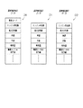
図2は、このような時系列フリーズフレームデータの概要を示している。
同図2に示されるように、時系列フリーズフレームデータは、車載機器の故障が検出された時点での該車載機器の稼働状況を示すデータ及びその該当する異常コードからなるデータD0、及び同故障が検出される前の車載機器の稼働状況を示すデータD1、及び同故障が検出されて後の車載機器の稼働状況を示すデータD2を有して構成される。なお、車載機器の稼働状況は通常、
・エンジンのクランク軸の回転態様を検出するクランクセンサによる出力値(エンジン回転数)。
・エンジンに吸入される空気量を検出するエアフローセンサによる出力値(吸入空気量)。
・トランスミッションの出力軸等に設けられている車速センサによる出力値(車速)。
・水温センサからの出力値(水温)。
・エンジンに吸入される空気の温度を検出する吸気温センサによる出力値(吸気温)。
・排気管内の酸素濃度を検出する酸素センサによる出力値。
等々、といった車載センサによる出力値によって示される。
FIG. 2 shows an outline of such time-series freeze frame data.
As shown in FIG. 2, the time-series freeze frame data includes data indicating the operating status of the in-vehicle device at the time when the in-vehicle device failure is detected, data D0 including the corresponding abnormal code, and the failure Data D1 indicating the operation status of the in-vehicle device before the detection of the failure, and data D2 indicating the operation status of the in-vehicle device after the failure is detected. The operating status of in-vehicle devices is usually
An output value (engine speed) by a crank sensor that detects the rotation mode of the crankshaft of the engine.
-Output value (intake air amount) by an air flow sensor that detects the amount of air taken into the engine.
-Output value (vehicle speed) by a vehicle speed sensor provided on the output shaft of the transmission.
-Output value from the water temperature sensor (water temperature).
-Output value (intake air temperature) by an intake air temperature sensor that detects the temperature of air taken into the engine.
-The output value from the oxygen sensor that detects the oxygen concentration in the exhaust pipe.
It is indicated by the output value from the in-vehicle sensor such as and so on.
このように、時系列フリーズフレームデータは、上記車載機器が故障に至る前からその後までの当該車載機器の稼働状況の推移を示しており、その故障発生の原因についてのより詳細な解析を可能とするものである。ただし、このような時系列フリーズフレームデータは、そのデータ構造上、上記車載機器が故障した時点での上記車載機器の稼働状況を示すデータD0のみからなるフリーズフレームデータよりも該データに含まれる情報量が多く、上記データメモリ111の空き容量への影響が避けられないものでもある。この点、この実施の形態にかかるエンジン制御装置110では上述の通り、フリーズフレームデータのその外部への退避が適正になされたと判断されることを条件に、該当するフリーズフレームデータを上記データメモリのバックアップ領域111bから積極的に消去するようにしている。このため、このような時系列フリーズフレームデータが採用される場合であれ、より高い信頼性の下でより多くの診断データを記憶保持させることができるようになり、ひいてはこうした時系列フリーズフレームデータに基づいて当該車載機器の故障発生の原因についてのより詳細な解析を行うことも可能となる。
In this way, the time-series freeze frame data shows the transition of the operating status of the in-vehicle device from before the on-vehicle device has failed until after that, and enables more detailed analysis of the cause of the failure. To do. However, such time-series freeze frame data includes, in its data structure, information included in the data rather than freeze frame data including only data D0 indicating the operation status of the in-vehicle device at the time when the in-vehicle device fails. The amount is large, and the influence on the free capacity of the
次に、このような時系列フリーズフレームデータを上記データメモリ111のバックアップ領域111bに格納する際に上記エンジン制御装置110によって行われるメモリ操作について、図3に基づいて説明する。なお、同図3中に示されるDATA(i,j)は、該当するデータのサンプリング順(i)及び種類(j)を示している。ただし、同図3中、サンプリング順が「0」に設定されているデータは、異常時にサンプリングされたデータである。
Next, a memory operation performed by the
この処理に際しては、まず、同図3(a)に示されるように、上記データメモリ111の作業領域111aに対し、上記車載機器の稼働状況を示すデータが時系列的に格納される。
In this process, first, as shown in FIG. 3A, data indicating the operation status of the in-vehicle device is stored in time series in the
具体的には、上記データメモリ111の作業領域111aに対し、所定時間(例えば「500ms」)毎にサンプリングされる4つのデータFD1〜FD4を、
(イ)データFD1〜FD4とそれらデータFD1〜FD4のサンプリング順に対応したアドレスとの関係が維持される。
及び、
(ロ)データFD1〜FD4が順次先入れ先出しにてシフトされる。
の論理積条件の下でその都度格納(更新)する。そして、例えば図3(b)に示されるタイミングにて上記車載機器の故障が検出されたときには、その時点での当該車載機器の稼働状況を示す上記データD0に対し、上記データFD1〜FD3を、上記故障が検出される前の車載機器の稼働状況を示すデータD1として設定する。また併せて、上記データFD4を、上記故障が検出されて後の車載機器の稼働状況を示すデータD2として設定する。そして、このように設定されたデータD0〜D2を上記時系列フリーズフレームデータとして関連付けした上で、該関連付けしたデータを、上記時系列フリーズフレームデータとして上記バックアップ領域111bに一時的に退避させる。これにより、時系列フリーズフレームデータが上記データメモリ111のバックアップ領域111bに格納されるようになる。
Specifically, for the
(A) The relationship between the data FD1 to FD4 and the addresses corresponding to the sampling order of the data FD1 to FD4 is maintained.
as well as,
(B) The data FD1 to FD4 are sequentially shifted in first-in first-out.
It is stored (updated) each time under the logical product condition. And, for example, when a failure of the in-vehicle device is detected at the timing shown in FIG. 3B, the data FD1 to FD3 for the data D0 indicating the operation status of the in-vehicle device at that time, It is set as data D1 indicating the operating status of the in-vehicle device before the failure is detected. In addition, the data FD4 is set as data D2 indicating the operating status of the in-vehicle device after the failure is detected. Then, after the data D0 to D2 set in this way are associated as the time series freeze frame data, the associated data is temporarily saved in the
図4及び図5は、このようなメモリ操作についてそのメモリ操作手順を示すフローチャートであり、次に、これら図4及び図5を参照して同メモリ操作手順についてさらに説明する。なお、図4は、所定時間(例えば「500ms」)毎に繰り返し行われる処理を示している。また、図5は、上記故障診断により上記車載機器の故障が検出されることに基づいて行われる処理を示している。 4 and 5 are flowcharts showing the memory operation procedure for such a memory operation. Next, the memory operation procedure will be further described with reference to FIGS. 4 and 5. FIG. 4 shows a process that is repeatedly performed every predetermined time (for example, “500 ms”). FIG. 5 shows processing performed based on the fact that a failure of the in-vehicle device is detected by the failure diagnosis.
同処理に際しては、上記エンジン制御装置110がまず、同図4に示されるように、ステップS111及びS112の処理として、上記データメモリ111の作業領域111aに対し、上記4つのデータFD1〜FD4(図3(a)参照)を、上記(イ)及び(ロ)の論理積条件の下に格納(更新)する。すなわち、上記ステップS111の処理では、上記データメモリ111の作業領域111aに既に格納されているデータFD1〜FD4(図3(a))のうちのデータFD2〜FD4をデータFD1〜FD3に各々シフトさせる。そして、次のステップS112の処理にて、その時点での上記車載機器の稼働状況を示すデータを同作業領域111aの上記サンプリング順に対応づけられたアドレスに新たに格納し、これをデータFD4とする。
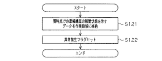
In this processing, the
そして次に、ステップS113の処理として、上記故障診断により上記車載機器の故障が検出された旨を示す異常発生フラグがセット状態にあるか否かを判断する。なお、この異常発生フラグは、例えば上記データメモリ111に格納され、当該エンジン制御装置110によってそのフラグ状態が操作されるものである。具体的には、図5に示されるように、この異常発生フラグは、上記故障診断により上記車載機器の故障が検出されたとき、上記データD0(図3(b)参照)が上記データメモリ111の作業領域111aに格納されたことを条件に(ステップS121)、そのフラグ状態がセット状態に操作される(ステップS122)。
Then, as a process of step S113, it is determined whether or not an abnormality occurrence flag indicating that a failure of the in-vehicle device is detected by the failure diagnosis is set. The abnormality occurrence flag is stored in, for example, the
したがって、このステップS113の処理において、上記異常発生フラグがセット状態にある場合には、上記ステップS112の処理にてシフトされたデータFD3と、上記ステップS113の処理にて新たに格納されたデータFD4との間で上記車載機器の故障が検出されており、先の図3(b)に示したような状況にあることとなる。そこでこの場合、上記エンジン制御装置110は、上記時系列フリーズフレームデータが格納されるだけの空き容量が上記バックアップ領域111bにあることを条件に(ステップS114)、上記作業領域111a内のデータD0及びデータFD1〜FD4を関連付けする(ステップS115)。次いで、この関連付けしたデータを、上記時系列フリーズフレームデータとして上記バックアップ領域111bに一時的に退避させる(ステップS115)。そして次に、ステップS116の処理として、上記異常発生フラグをリセット状態に操作した時点で、この制御を終了する。
Accordingly, in the process of step S113, when the abnormality occurrence flag is set, the data FD3 shifted in the process of step S112 and the data FD4 newly stored in the process of step S113 are displayed. The failure of the in-vehicle device is detected between the two and the situation is as shown in FIG. Therefore, in this case, the
ただし、上記ステップS114の処理において、上記時系列フリーズフレームデータを一時的に退避させるだけの空き容量が上記バックアップ領域111bにない場合には、上記ステップS115の処理を行うことなく、上記ステップS116の処理を実行した時点で、この制御を終了することとなる。
However, in the process of step S114, if the
一方、上記ステップS113の処理において、上記異常発生フラグがセット状態にない場合には、先の図3(a)に示したような状況にあることとなる。したがってこの場合、該異常発生フラグがセット状態にあると判断されるようになるまで、上記ステップS111及びS112の処理を所定時間毎に繰り返し行うこととなる。 On the other hand, if the abnormality occurrence flag is not set in the process of step S113, the situation is as shown in FIG. Therefore, in this case, the processes in steps S111 and S112 are repeated every predetermined time until it is determined that the abnormality occurrence flag is set.
次に、こうして上記バックアップ領域111bに格納された時系列フリーズフレームデータの該バックアップ領域111bからの消去についてそのメモリ操作手順を図6に基づいて説明する。なお、図6は、同メモリ操作手順をフローチャートとして示したものである。また、このメモリ操作において、エンジン制御装置110と管理センター200との間での無線通信は、上記通信制御装置140の仲介によって行われる。
Next, a memory operation procedure for erasing the time-series freeze frame data stored in the
すなわち、いま、上記バックアップ領域111bに上記時系列フリーズフレームデータが格納されたとすると(ステップS131)、上記エンジン制御装置110はまず、該当する時系列フリーズフレームデータを上記管理センター200に無線通信により送信(転送)する(ステップS132)。次いで、この通信の適正性を判断し、該通信が適正になされたとの判断の下に(ステップS133)、該当する時系列フリーズフレームデータを上記バックアップ領域111bから消去する(ステップS134)。すなわち、この実施の形態では、上記バックアップ領域111bに上記時系列フリーズフレームデータが格納される都度、上記エンジン制御装置110が、こうした処理(ステップS132〜S134)を行うことによって、上記バックアップ領域111b内の空き容量を好適に確保するようにしている。
That is, when the time-series freeze frame data is stored in the
なお、この実施の形態では、上記通信が適正になされたとの判断(ステップS133)を、上記時系列フリーズフレームデータが送信されて後、所定期間内に上記管理センター200から同時系列フリーズフレームデータの受信が適正に行われた旨を示す情報の通知(受信完了通知)があったことに基づいて行うようにしている。ただしこの際、該受信完了通知が受信されなかった場合には、同エンジン制御装置110は次に、該当するフリーズフレームデータを上記管理センター200に再送信するための処理(ステップS135〜S137)を行うこととなる。すなわち、まず、ステップS135の処理として、上記時系列フリーズフレームデータの再送信の連続実行回数を計数し、該計数した連続実行回数が、上記車両100や上記管理センター200の通信機能自体の故障が懸念される回数である上限値を超えたか否かを判断する。そして後述するが、該計数した連続実行回数が同上限値以下である場合には、次にステップS136及びS137の処理として、上記管理センター200との間での通信環境が整っていると判断されるようになるまで待機する。そしてこの結果、上記管理センター200との間での通信環境が整っていると判断されるようになれば、同エンジン制御装置110は次に、上記ステップS132の処理に再度移行し、このステップS132の処理にて、上記時系列フリーズフレームデータを再送信する。すなわちこの場合、基本的には、上記管理センター200から上記受信完了通知が送信されるようになるまで、上記ステップS135〜S137、及びステップS132の処理が繰り返し実行されることとなる。
In this embodiment, it is determined that the communication has been properly performed (step S133). After the time-series freeze frame data is transmitted, the
ただし、こうした再送信処理が繰り返し行われた結果、上記ステップS135の処理において、上記計数した連続実行回数が上記上限値を超えた場合には、上記車両100や上記管理センター200の通信機能自体に異常が生じている懸念があるとして、この再送信処理を中止する。そして、MILランプを通じてその異常状況をドライバに通知する(ステップS138)。なお、このMILランプを点灯した時点で、当該メモリ操作(図6)これ自体の処理の実行を禁止するようにしてもよい。
However, as a result of the repeated re-transmission process, if the counted number of continuous executions exceeds the upper limit in the process of step S135, the communication function itself of the
図7は、上記エンジン制御装置110により行われる上記通信環境判定(ステップS137)についてその処理手順を示したフローチャートであり、次に、この図7を参照して同処理について説明する。
FIG. 7 is a flowchart showing a processing procedure for the communication environment determination (step S137) performed by the
ちなみに、上記車両100及び管理センター200の間では、上記時系列フリーズフレームデータに関するデータ以外のデータについての情報授受も併せて行われている。この点、この実施の形態にかかるエンジン制御装置110では、該情報授受にかかる感度の状況に基づいて上記無線通信を行い得る位置に上記車両100があるか否かを判断し、この判断を通じて当該通信環境判定を行うようにしている。
Incidentally, between the
すなわち、当該通信環境判定に際しては、同図7に示されるように、上記エンジン制御装置110がまず、ステップS141の処理として、受信履歴フラグをリセット状態に操作する。そして、上記管理センター200から上記時系列フリーズフレームデータに関するデータ以外のデータが送信された場合には(ステップS142)、同受信履歴フラグをセット状態に操作した時点で(ステップS143)、この制御を終了する。これにより、次のステップS137の処理(図6参照)では、この受信履歴フラグがセット状態にあることに基づいて上記通信環境が良好であると判断されるようになる。
That is, when determining the communication environment, as shown in FIG. 7, the
一方、上記ステップS142の処理において、上記管理センター200から上記時系列フリーズフレームデータに関するデータ以外のデータが送信されなかった場合には、上記ステップS143の処理を行うことなく、その時点でこの制御を終了する。すなわちこの場合、次のステップS137の処理(図6参照)では、この受信履歴フラグがリセット状態にあることに基づいて上記通信環境が良好でないと判断され、このステップS137の処理において上記通信環境が良好であると判断されるようになるまで、上記ステップS136の処理を繰り返し行うこととなる。
On the other hand, if no data other than the data related to the time-series freeze frame data is transmitted from the
ところで、上記時系列フリーズフレームデータの退避処理中に上記車両100のIGスイッチがオフ操作されることも考えられる。そしてこの際、車載バッテリから当該エンジン制御装置110への給電状態が解除されるようなことがあれば、上記時系列フリーズフレームデータとしての信頼性が低下することにもなりかねない。そこで、この実施の形態にかかるエンジン制御装置110では、上記時系列フリーズフレームデータの退避中に上記車両100のIGスイッチがオフ操作されるときには、車載バッテリから当該エンジン制御装置110への給電状態をその退避処理に要する時間だけ保持するようにしている。
Incidentally, it is conceivable that the IG switch of the
図8は、IGスイッチがオフ操作される際に上記エンジン制御装置110によって行われる処理についてその処理手順をフローチャートとして示したものである。
すなわち、いま、IGスイッチがオフ操作されたとすると、上記エンジン制御装置110はまず、ステップS151の処理として、メインリレー制御に基づき車載バッテリからの給電状態を保持する。そして次に、ステップS152の処理として、上記時系列フリーズフレームデータが退避中にあるか否かを判断する。なお、ここでの退避中とは、上記作業領域111aから上記バックアップ領域111bへの退避中と、上記バックアップ領域111bから上記管理センター200内の記憶装置201への退避中とがあり、それらいずれかの退避処理が行われているときには、該退避処理が終了するまで待機する。そしてその結果、上記時系列フリーズフレームデータの退避処理が終了すれば、上記メインリレー制御に基づく車載バッテリからの給電状態の保持を解除した時点で(ステップS153)、この制御を終了する。
FIG. 8 is a flowchart showing a processing procedure of processing performed by the
That is, now, assuming that the IG switch is turned off, the
以上説明したように、この実施の形態にかかる車両診断装置によれば、以下に記載するような優れた効果が得られるようになる。
(1)内蔵するデータメモリ111に格納されているフリーズフレームデータの外部への退避が適正になされたと判断されることを条件に、該当するフリーズフレームデータを上記データメモリ111から消去するようにしたため、より高い信頼性の下でより多くの診断データを記憶保持させることができるようになる。
As described above, according to the vehicle diagnostic apparatus according to this embodiment, the following excellent effects can be obtained.
(1) Since the freeze frame data stored in the built-in
(2)上記フリーズフレームデータを、上記管理センター200内の記憶装置201に無線通信にて退避させることとしたため、車両100内の記憶媒体の容量を好適に抑制することができるようになる。また、車両メンテナンスの面で適切なサービスの実現が可能となる。
(2) Since the freeze frame data is saved in the
(3)上記フリーズフレームデータを送信した後、所定期間内に上記管理センター200から上記受信完了通知が送信されないことに基づいて当該フリーズフレームデータを上記管理センター200に再送信することとした。このため、上記車両100及び上記管理センター200間での無線通信による情報授受をより確実に行うことができるようになる。
(3) After transmitting the freeze frame data, the freeze frame data is retransmitted to the
(4)上記時系列フリーズフレームデータの連続送信回数が上記上限値を超えたことに基づいてMILランプを点灯することとしたため、上記車両100や上記管理センター200の通信機能自体の異常状況をドライバに通知することができるようになる。
(4) Since the MIL lamp is turned on when the number of continuous transmissions of the time-series freeze frame data exceeds the upper limit value, the driver detects the abnormal state of the communication function itself of the
(5)上記時系列フリーズフレームデータの送信に際して上記管理センター200との間での通信環境が整っているか否かを判断し(ステップS136及びS137)、該通信環境が整っているとの判断の下に当該時系列フリーズフレームデータを送信するようにした。このため、上記車両100と上記管理センター200との間での通信を適切に行うことができるようになる。
(5) When transmitting the time-series freeze frame data, it is determined whether or not a communication environment with the
(6)車両100と管理センター200との間では、上記時系列フリーズフレームデータに関するデータ以外のデータについての情報授受も併せて行われ、該情報授受にかかる感度の状況に基づいて上記無線通信を行い得る位置に当該車両100があるか否かを判断するようにした。すなわち、上記無線通信を行い得る位置に車両100があることに基づいて上記通信環境が整っていることを判断するようにしたため、該判断を的確且つ容易に行うことができるようになる。
(6) Information other than data related to the time-series freeze frame data is also exchanged between the
(7)上記フリーズフレームデータとして、車載機器の故障が検出された時点及びその前後での当該車載機器の稼働状況を示すデータである時系列フリーズフレームデータを採用するようにした。このため、こうした時系列フリーズフレームデータに基づいて当該車載機器の故障発生の原因についてのより詳細な解析を行うことが可能となる。 (7) As the freeze frame data, time-series freeze frame data, which is data indicating the operation status of the in-vehicle device before and after the failure of the in-vehicle device is detected, is adopted. For this reason, it becomes possible to perform a more detailed analysis about the cause of failure occurrence of the in-vehicle device based on such time-series freeze frame data.
(8)上記データメモリ111として、作業領域111a及びバックアップ領域111bからなるランダムアクセスメモリ(RAM)を採用することとした。そして、上記車載機器の稼働状況を示すデータを作業領域111aに時系列的に格納するとともに、上記故障診断により車載機器の故障が検出されたときには、その時点での当該車載機器の稼働状況を示すデータと同車載機器のその前後の稼働状況を示すデータとを関連付けすることとした。そして、該関連付けしたデータを上記時系列フリーズフレームデータとして上記バックアップ領域111bに一時的に退避させるようにしたため、該時系列フリーズフレームデータが外部の管理センター200へ退避されるまでの間、同時系列フリーズフレームデータを上記データメモリ111にて適切に記憶保持することができるようになる。
(8) As the
(9)上記時系列フリーズフレームデータの退避中に上記車両100のIGスイッチがオフ操作されることに基づいて車載バッテリから当該エンジン制御装置110への給電状態をその退避に要する時間だけ保持するようにしたため、上記時系列フリーズフレームデータとしての信頼性を好適に維持することができるようになる。
(9) Based on the fact that the IG switch of the
(第2の実施の形態)
次に、この発明にかかる車両診断装置についてその第2の実施の形態を示す。なお、この実施の形態の車両診断装置も、車載エンジンを含めた車載機器の稼働状況に応じて変化する物理量を検出するセンサからの出力信号に基づいてそれらの故障診断を行うものとなっており、具体的には、例えば各種の車載機器を分散制御する複数の電子制御装置のうちの1つであるエンジン制御装置110からなる。また、該エンジン制御装置110が内蔵するデータメモリ111も、先の第1の実施の形態(図1)とほぼ同様のメモリ構造となっており、上記故障診断により車載機器の故障が検出されたときには、同エンジン制御装置110が、このデータメモリ111に対し、
・同故障が検出された時点での当該車載機器の稼働状況を示すデータと同車載機器のその前後の稼働状況を示すデータとを上記データメモリ111の作業領域111aにて関連付けし、該関連付けしたデータを上記時系列フリーズフレームデータとして上記バックアップ領域111bに一時的に退避させる。
・上記データメモリ111のバックアップ領域111bに格納された時系列フリーズフレームデータを別途設けられた記憶装置に対し通信にて待避させつつ、この通信の適正性を判断して、同通信が適正になされたとの判断の下に、該当する時系列フリーズフレームデータを上記バックアップ領域111bから消去する。
等々、といったメモリ操作を行う点についても、先の第1の実施の形態とほぼ同様である。またこれも同様、この実施の形態のエンジン制御装置110も、上記時系列フリーズフレームデータの退避中に車両のIGスイッチがオフ操作されることに基づいて車載バッテリから当該エンジン制御装置110への給電状態をその退避処理に要する時間だけ保持する。
(Second Embodiment)
Next, a second embodiment of the vehicle diagnostic apparatus according to the present invention will be described. In addition, the vehicle diagnosis apparatus of this embodiment also performs failure diagnosis based on an output signal from a sensor that detects a physical quantity that changes in accordance with the operating status of in-vehicle devices including an in-vehicle engine. Specifically, for example, the
The data indicating the operating status of the in-vehicle device at the time when the failure is detected and the data indicating the operating status before and after the in-vehicle device are associated in the
・ The time series freeze frame data stored in the
The point of performing the memory operation such as, etc. is almost the same as that of the first embodiment. Similarly, the
ただし、この実施の形態にかかる車載ネットワークでは、上記各種の車載機器を分散制御する複数の電子制御装置のうちの1つとして、図9に示されるように、ナビゲーションシステムを構成するナビゲーション制御装置(車載制御装置)150が接続されている。このナビゲーション制御装置150は、例えばハードディスクなどからなる大規模容量の記憶装置151を内蔵しており、この実施の形態にかかるエンジン制御装置110では、該記憶装置151に対して上記時系列フリーズフレームデータを通信バスBSを介して退避させる。そして、この退避が適切になされたことを条件に、該当する時系列フリーズフレームデータを上記バックアップ領域111bから消去するようにしている。このような構成であれ、当該エンジン制御装置110が内蔵する上記データメモリ111の容量を好適に抑制することができるようになる。
However, in the vehicle-mounted network according to this embodiment, as one of a plurality of electronic control devices that perform distributed control of the various vehicle-mounted devices, as shown in FIG. 9, a navigation control device ( In-
図10は、この実施の形態にかかるメモリ操作についてそのメモリ操作手順を示したものであり、次にこの図10を参照して同メモリ操作手順を説明する。
すなわち、いま、上記バックアップ領域111bに上記時系列フリーズフレームデータが格納されたとすると(ステップS231)、上記エンジン制御装置110はまず、該当する時系列フリーズフレームデータを上記ナビゲーション制御装置150に通信バスBSを介して送信(転送)する(ステップS232)。次いで、この通信の適正性を判断し、該通信が適正になされたとの判断の下に(ステップS233)、該当する時系列フリーズフレームデータを上記バックアップ領域111bから消去する(ステップS234)。すなわち、この実施の形態においても、上記バックアップ領域111bに上記時系列フリーズフレームデータが格納される都度、上記エンジン制御装置110が、こうした処理(ステップS232〜S234)を行うことで、上記バックアップ領域111b内の空き容量を好適に確保するようにしている。
FIG. 10 shows the memory operation procedure for the memory operation according to this embodiment. Next, the memory operation procedure will be described with reference to FIG.
That is, when the time-series freeze frame data is stored in the
なお、この実施の形態では、上記通信が適正になされたか否かの判断(ステップS233)を、上記車載ネットワークの通信プロトコルに基づいて行うようにしている。また、このステップS233の処理において、上記通信の適正性が確認されない場合の処理(再送信の処理など)についても同様、上記車載ネットワークの通信プロトコルに基づいて行うようにしている。 In this embodiment, the determination as to whether or not the communication has been performed properly (step S233) is made based on the communication protocol of the in-vehicle network. Further, in the process of step S233, the process when the appropriateness of the communication is not confirmed (retransmission process or the like) is similarly performed based on the communication protocol of the in-vehicle network.
以上説明したように、この第2の実施の形態にかかる車両診断装置によっても、基本的には先の第1の実施の形態の前記(1)及び(7)〜(9)の効果と同等、あるいはそれに準じた効果を得ることができるようになる。 As described above, the vehicle diagnostic apparatus according to the second embodiment is basically equivalent to the effects (1) and (7) to (9) of the first embodiment. Or, an effect equivalent to that can be obtained.
なお、この発明にかかる車両診断装置は、上記ナビゲーション制御装置が車載されるシステムにあっては、上記第2の実施の形態として示した処理態様に限らず、これを適宜に変形した、例えば以下に例示する態様にて実施することもできる。 The vehicle diagnosis apparatus according to the present invention is not limited to the processing mode shown as the second embodiment in the system in which the navigation control apparatus is mounted on a vehicle. It can also be implemented in the embodiment exemplified in.
(変形例)
上記実施の形態では、上記ナビゲーション制御装置150内の記憶装置151を上記時系列フリーズフレームデータの最終退避先として用いることとした。ただし、上記車載ネットワークが、図11に示されるように、先の図1に示した管理センター200との間での情報授受を行うものである場合には、例えば図12に示される処理手順に基づき、上記記憶装置151に退避された時系列フリーズフレームデータを上記管理センター200に無線通信にてさらに退避させるようにすることもできる。このような処理態様を採用するようにすることで、
・車両外部の管理センター200が、該当する車両のユーザ(ドライバ)に対して上記車載機器の故障が検出された旨の通知を行う。
・車載機器の故障を例えば車種や生産ロット毎に統計し、その統計の結果を車両開発(安全対策など)に役立てる。
等々、上記時系列フリーズフレームデータの有効利用がより容易なものとなり、特に車両メンテナンスの面で適切なサービスの実現が可能となる。
(Modification)
In the above embodiment, the
The
・ Statistics of breakdowns of in-vehicle devices, for example, for each vehicle type and production lot, and use the results of the statistics for vehicle development (safety measures, etc.).
The time-series freeze frame data can be effectively used more easily, and an appropriate service can be realized particularly in terms of vehicle maintenance.
以下、この変形例において上記ナビゲーション制御装置150によって行われるメモリ操作について図12を参照して説明する。なお、図12は、こうしたメモリ操作についてそのメモリ操作手順をフローチャートとして示したものである。また、同処理は、所定期間毎に繰り返し行われる。
Hereinafter, a memory operation performed by the
同処理に際しては、上記ナビゲーション制御装置150がまず、ステップS241の処理として、上記エンジン制御装置110から上記時系列フリーズフレームデータが送信されたか否かを判断する。そしてその結果、該送信があると判断された場合には、この時系列フリーズフレームデータを上記記憶装置151に格納するとともに(ステップS242)、同時系列フリーズフレームデータを上記管理センター200に無線通信にて送信する(ステップS243及びS244)。そして次に、この通信の適正性を判断し、該通信が適正になされたとの判断の下に(ステップS245)、該当する時系列フリーズフレームデータを上記記憶装置151から消去する(ステップS246)。
In this process, the
一方、上記ステップS241の処理において、上記エンジン制御装置110からの送信がなかった場合には、上記ステップS242の処理を行うことなく、上記ステップS243〜S246の処理を通じて上記時系列フリーズフレームデータを上記記憶装置151から消去することとなる。ただしこの際、上記ステップS243の処理では、上記記憶装置151内に上記時系列フリーズフレームデータが格納されていないと判断されることもあり、この場合には、その時点で同制御を終了することとなる。
On the other hand, if there is no transmission from the
なお、この変形例においても、上記通信が適正になされたとの判断(ステップS245)を、上記時系列フリーズフレームデータが送信されて後、所定期間内に上記管理センター200から同時系列フリーズフレームデータの受信が適正に行われた旨を示す情報の通知(受信完了通知)があったことに基づいて行うようにしている。
In this modification as well, it is determined that the communication has been properly performed (step S245). After the time series freeze frame data is transmitted, the
以上説明したように、このような変形例によっても、上記(1)及び(7)〜(9)と同様の効果が得られるようになる。また、先の第1の実施の形態の前記(2)の効果と同等、あるいはそれに準じた効果を得ることもできるようになる。
(他の実施の形態)
なお、上記各実施の形態は、以下のように変更して実施することもできる。
As described above, the same effects as in the above (1) and (7) to (9) can be obtained by such a modification. In addition, an effect equivalent to or equivalent to the effect (2) of the first embodiment can be obtained.
(Other embodiments)
The above-described embodiments can be implemented with the following modifications.
・上記各実施の形態の場合も含めて、上記データメモリ111の作業領域111aには通常、上記車載機器の稼働状況を示す複数項目のデータが格納され、これら複数項目のデータの一部(エンジン回転数や吸入空気量など)が上記時系列フリーズフレームデータとして採用される。そして、上記各実施の形態では、このような時系列フリーズフレームデータを外部の記憶装置に通信にて退避させつつ、この通信の適正性を判断して、同通信が適正になされたとの判断の下に、該当する時系列フリーズフレームデータを上記バックアップ領域111bから消去するようにしている。ただし、上記作業領域111aに格納されている上記複数項目のデータのうちの上記時系列フリーズフレームデータとして採用されないデータについても、上記外部の記憶装置に対し併せて待避させるようにすれば、このようなデータに基づくより詳細な解析が可能になる。図13は、このようなデータの退避処理についてその退避処理手順を示すフローチャートであり、次にこの図13を参照して同退避処理手順を説明する。なおここでは、上記データの退避先として、上記管理センター200内の記憶装置201を採用することとする。すなわち、いま、上記バックアップ領域111bに上記時系列フリーズフレームデータが格納されたとすると(ステップS331)、上記エンジン制御装置110はまず、車載バッテリから当該エンジン制御装置110への給電状態が継続されているか否かをトリップ判定フラグのフラグ状態に基づいて判断する(ステップS332)。なお、このトリップ判定フラグは、上記故障診断により上記車載機器の異常が検出されることに基づきセット状態に操作されるとともに、車両のIGスイッチがオン操作されることに基づきリセット状態に操作されるものである。したがって、このステップS332の処理において、上記トリップ判定フラグがセット状態にある場合には、当該エンジン制御装置110への給電状態が継続されているとして、上記エンジン制御装置110は次に、ステップS333の処理に移行する。そしてこのステップS333の処理において、上記バックアップ領域111bに格納されている時系列フリーズフレームデータのほか、上記作業領域111aに格納されているデータのうちの上記故障解析に有益なデータ(例えば各種センサの出力値や入出力ポートの状態など)を送信する。ただし、上記ステップS332の処理において、上記トリップ判定フラグがリセット状態にある場合には、当該エンジン制御装置110への給電状態が一度遮断されており、作業領域111a内のデータは既に失われている。したがってこの場合、同エンジン制御装置110は、上記バックアップ領域111bに退避された時系列フリーズフレームデータのみを上記管理センター200に送信することとなる(ステップS334)。そしていずれにしろ、上記データメモリ111の記憶内容が上記管理センター200に無線通信により送信されて後は、この通信の適正性を判断し、該通信が適正になされたとの判断の下に(ステップS335)、該当する時系列フリーズフレームデータを上記バックアップ領域111bから消去する(ステップS336)。
Including the case of each of the above embodiments, the
・先の図12や図13に示した処理手順においては、上記受信完了通知が受信されなかったことに基づき(ステップS245、S335)、該当するデータを上記管理センター200に再送信するようにしてもよい。例えば、上記第1の実施の形態のステップS135〜S137の処理を実行して後に、上記ステップS244やステップS332の処理を再度行うようにすれば、上記管理センター200に対して該当するデータを適切に送信することができるようになる。なお、この場合には特に、上記第1の実施の形態のステップS138の処理(MILランプの点灯)も併せて行うようにすることが実用上望ましい。
In the processing procedure shown in FIG. 12 or FIG. 13, based on the fact that the reception completion notification has not been received (steps S245 and S335), the corresponding data is retransmitted to the
・ナビゲーション制御装置150が車載されるシステムにあって、上記エンジン制御装置110は、上記通信環境判定(ステップS136)を、同ナビゲーション制御装置150を通じて得られる位置情報に基づいて行うようにしてもよい。すなわちこの場合、この通信環境判定に際しては、図14に示されるように、まず、ステップS311の処理として、通信フラグをリセット状態に操作する。そしてこの上で、上記ナビゲーション制御装置150からの位置情報に基づき、
(ハ)車両が通信可能地域にある(ステップS312)。
及び、
(ニ)車両がトンネル内や地下などの特殊な条件下にない(ステップS313)。
の論理積条件が満たされているか否かの判断を行う。そしてその結果、この論理積条件が満たされている場合には、上記通信フラグをセット状態に操作した時点で(ステップS314)、この制御を終了する。これにより、次のステップS137の処理(図6参照)において、この通信フラグがセット状態にあることに基づいて上記管理センター200との間の通信環境が良好であると判断されるようになる。ただし、上記(ハ)及び(ニ)の論理積条件が満たされていなかった場合には(ステップS312及びS313)、上記ステップS314の処理を行うことなく、その時点でこの制御を終了する。すなわちこの場合、上記ステップS137の処理(図6参照)では、上記管理センター200との間の通信環境が良好でないと判断され、このステップS137の処理において該通信環境が良好であると判断されるようになるまで、この図14に例示した処理が繰り返し行われることとなる。
In the system in which the
(C) The vehicle is in a communicable area (step S312).
as well as,
(D) The vehicle is not in a special condition such as in a tunnel or underground (step S313).
It is determined whether or not the logical product condition of is satisfied. As a result, if the logical product condition is satisfied, the control is terminated when the communication flag is set to the set state (step S314). Thereby, in the process of the next step S137 (see FIG. 6), it is determined that the communication environment with the
・上記時系列フリーズフレームデータに、上記故障診断により車載機器の故障が検出された時刻を示す時刻情報を付与するようにしてもよい。このような構成では、上記管理センター200側にて、その受信時刻との対比に基づき、該時系列フリーズフレームデータが当該管理センター200に送信されなかった期間、すなわち同時系列フリーズフレームデータが上記バックアップ領域111bから消去されなかった期間を認識することができるようになる。
-You may make it give the time information which shows the time when the failure of the vehicle equipment was detected by the said failure diagnosis to the said time series freeze frame data. In such a configuration, on the
・上記時系列フリーズフレームデータに、上記故障診断により車載機器の故障が検出された時刻から、バックアップ領域111bに上記時系列フリーズフレームデータが格納されるだけの空き容量がなく、且つ、車両のIGスイッチがオン状態にあった総時間を示す時間データ(時間情報)を付与するようにしてもよい。このような構成では、上記故障診断が実行されているにもかかわらず上記時系列フリーズフレームデータが上記バックアップ領域111bから消去されなかった時間を容易に認識することができるようになる。図15は、このような時間データを上記時系列フリーズフレームデータに付与する場合に上記エンジン制御装置110によって行われるメモリ操作についてそのメモリ操作手順を示すフローチャートであり、次にこの図15を参照して同メモリ操作手順を説明する。なおこの処理は、例えば1秒毎に繰り返し実行される。またここでは、上記バックアップ領域111bが、図16に示されるように、上記時系列フリーズフレームデータを3つまで格納可能な容量に設定されている場合を想定している。また、同図16中に示されるDATA(r,s,t)は、該当するデータのフレーム番号(r)及びサンプリング順(i)及び種類(j)を示している。ただし、同図16中、サンプリング順が「0」に設定されているデータは、異常時にサンプリングされたデータである。また、上記時間データは、この異常時にサンプリングされたデータに各々付与されるものとする。すなわち、この処理に際しては、上記エンジン制御装置110がまず、図15に示されるように、
(ホ)上記バックアップ領域111bに新たな時系列フリーズフレームデータが格納されるだけの空き容量がない(ステップS321)。
(ヘ)車両のIGスイッチがオン状態にある(ステップS322)。
の論理積条件が満たされているか否かの判断を行う。そしてその結果、この(ホ)及び(ヘ)の論理積条件が満たされた場合には、上記バックアップ領域111bに格納されている3つの時系列フリーズフレームデータFFD1〜FFD3の上記時間データに対し、「1」を各々加算する。一方、上記(ホ)及び(ヘ)の論理積条件が満たされなかった場合には、上記ステップS323の処理を行うことなく、その時点で同制御を一旦終了する。こうした処理が1秒毎に繰り返し実行されることで、上記時系列フリーズフレームデータに付与された上記時間データが、上記故障診断が実行されているにもかかわらず上記時系列フリーズフレームデータが上記バックアップ領域111bから消去されなかった総時間を示すようになる。
The time series freeze frame data does not have enough free space to store the time series freeze frame data in the
(E) There is not enough free space in the
(F) The IG switch of the vehicle is in an on state (step S322).
It is determined whether or not the logical product condition of is satisfied. As a result, when the logical product condition of (e) and (f) is satisfied, the time data of the three time-series freeze frame data FFD1 to FFD3 stored in the
・上記エンジン制御装置(車両診断装置)110が通信線を介して外部ツールと接続可能とされるものであるときには、例えばディーラーや修理工場などにおいて、該外部ツールから上記時系列フリーズフレームデータについての出力要求が通知されることもある。ただしこの際、上記時系列フリーズフレームデータが車両外部の記憶装置に退避済みであり、同データが上記データメモリ111から既に消去されているとすれば、上記ディーラーや修理工場などにおいて適宜のサービスが適切に提供されなくなるなどといった懸念が生ずる。この点、当該エンジン制御装置110が、図17に示される手順に従って、上記外部ツールからの出力要求に応答するようにすれば、こうした懸念も好適に解消されるようになる。なおこの処理は、所定期間毎に繰り返し行われる。すなわち、いま、上記外部ツールから上記時系列フリーズフレームデータについての出力要求が通知されたとすると(ステップS341)、上記エンジン制御装置110がまず、同図17に示されるように、上記管理センター200に対して上記時系列フリーズフレームデータの返送要求を通知する(ステップS342)。そして次に、上記返送要求の通知の後、所定期間内に上記管理センター200からのデータ返送があったか否かを判断する(ステップS343)。そしてその結果、上記時系列フリーズフレームデータが返送された場合には、この返送されたデータを上記外部ツールに出力する(ステップS344)。ただし、上記ステップS343の処理において、上記時系列フリーズフレームデータが返送されなかった場合には、上記時系列フリーズフレームデータが上記管理センター200にて記憶保持されている旨を示す情報を外部ツールに出力する(ステップS345)。
When the engine control device (vehicle diagnostic device) 110 can be connected to an external tool via a communication line, for example, at a dealer or a repair shop, the time series freeze frame data from the external tool An output request may be notified. However, at this time, if the time-series freeze frame data has been saved in the storage device outside the vehicle and the data has already been deleted from the
・上記第1の実施の形態のステップS135〜S137の処理は、上記時系列フリーズフレームデータを再送信する際に限らず、該時系列フリーズフレームデータを送信する都度行うようにしてもよい。 -The process of step S135-S137 of the said 1st Embodiment is not restricted to retransmitting the said time series freeze frame data, You may make it perform whenever it transmits this time series freeze frame data.
・エンジン制御装置(車両診断装置)110が、上記管理センター200との間での無線通信を行う通信手段を内蔵するものであれば、上記時系列フリーズフレームデータの外部の記憶装置への退避に際し、車内に構築される車載ネットワークなどの通信線にかかる負荷を好適に抑制することができるようになる。
If the engine control device (vehicle diagnosis device) 110 includes a communication means for performing wireless communication with the
・上記時系列フリーズフレームデータの上記バックアップ領域111bへの格納手順は任意である。
・時系列フリーズフレームデータは、上記車載機器が故障(異常)に至る前からその後までの当該車載機器の稼働状況の推移を示すものであればよく、そのサンプリングされるデータ数などは任意である。
The procedure for storing the time-series freeze frame data in the
-Time-series freeze frame data may be any data as long as it shows the transition of the operating status of the in-vehicle device from before the on-vehicle device has failed (abnormal) until after that, and the number of sampled data is arbitrary. .
・フリーズフレームデータとして時系列フリーズフレームデータを必ずしも採用してなくてもよい。要は、故障診断により車載機器の故障が検出されたときの当該車載機器の稼働状況を示すデータであればよい。 -Time series freeze frame data may not necessarily be adopted as freeze frame data. In short, any data may be used as long as it indicates the operation status of the in-vehicle device when a failure of the in-vehicle device is detected by the failure diagnosis.
・上記通信環境判定(ステップS136)にかかる判定手法は任意であり、上記管理センター200との間での情報授受が適切に行い得る状況にあるか否かを認識することができる手法であればよい。
The determination method according to the communication environment determination (step S136) is arbitrary, as long as it is a method that can recognize whether or not information can be appropriately exchanged with the
・車両と管理センターとの間での通信に異常が生じた旨を示す情報のユーザ通知(ステップS138)については、Eメールを利用した通知手法なども含めて、その手法は任意である。 -About the user notification (step S138) of the information which shows that abnormality has arisen in communication between a vehicle and a management center, the method including the notification method using E-mail etc. is arbitrary.
・車両と管理センターとの間での通信に異常が生じた旨を示す情報のユーザ通知(ステップS138)は必ずしも行わなくてもよい。またこれも同様、上記フリーズフレームデータの再送信についても必ずしも実行しなくてもよい。 -The user notification (step S138) of information indicating that an abnormality has occurred in communication between the vehicle and the management center may not necessarily be performed. Similarly, the freeze frame data need not be retransmitted.
・上記データメモリ111は、任意の揮発性メモリ及び任意の不揮発性メモリ(ハードディスクも含む)からなるメモリであってもよい。
・データメモリ111を、揮発性メモリ及び不揮発性メモリのいずれかのみから設けてもよい。ただし、データメモリ111が揮発性メモリのみからなる場合には、車載バッテリから当該エンジン制御装置110への給電が継続されている期間中に、同データメモリ111内の全てのフリーズフレームデータを外部の記憶装置に通信にて退避させることとなる。またこの場合、同通信が適正になされたと判断された際の消去対象は、揮発性メモリに格納されているフリーズフレームデータとなる。
The
The
・上記フリーズフレームデータの送信中に上記車両のIGスイッチがオフ操作されることに基づいて車載バッテリから当該エンジン制御装置110への給電状態をその通信に要する時間だけ必ずしも保持しなくてもよい。
The power supply state from the in-vehicle battery to the
・車両診断装置は、エンジン制御装置110に限らず、任意の制御装置であればよい。
・上記データメモリ111からの退避及び消去の対象となるデータとしては、フリーズフレームデータに限らず、車両の異常解析に用いられるデータ(異常解析用のデータ)であればよい。なお、異常解析用のデータとは、例えばセンサ類やアクチュエータ類、あるいはエンジン制御装置等にて異常が発生した状況に関連するデータであって、その異常を解析する上で参考となる情報である。例えば、アクチュエータの劣化を検出をするために、車両販売後の所定時間毎又は所定走行距離毎にアクチュエータの機差学習値(経年変化により変化するもの)を定期的に記憶しておき、その機差学習値の変化に基づきアクチュエータの劣化を検出するような場合がある。異常解析用のデータには、このような履歴情報となるような機差学習値も含まれる。
The vehicle diagnostic device is not limited to the
The data to be saved and erased from the
100…車両、101…通信バス、110…エンジン制御装置、120…トランスミッション制御装置、130…ブレーキ制御装置、140…通信制御装置、150…ナビゲーション制御装置、151、201…記憶装置、200…管理センター、BS…通信バス。
DESCRIPTION OF
Claims (22)
前記記憶装置は、車両の外部にて前記フリーズフレームデータを管理する管理センターに設けられてなり、
前記車両と前記管理センターとの間では、無線通信により前記フリーズフレームデータの待避が行われるとともに、前記フリーズフレームデータに関するデータ以外のデータについての情報授受も併せて行われ、
前記メモリ操作手段は、前記管理センターからフリーズフレームデータの受信が適正に行われた旨を示す情報が通知されることに基づいて前記通信が適正になされたことを判断するものであって、前記フリーズフレームデータに関するデータ以外のデータについての情報授受にかかる感度の状況に基づき前記無線通信を行い得る位置に前記車両があるか否かを判断し、該位置に車両があると判断したとき前記車両と前記管理センターとの間での通信環境が整っているとして前記フリーズフレームデータを送信する
ことを特徴とする車両診断装置。 When a failure diagnosis of an in-vehicle device is performed based on the sensor output of a sensor that detects a physical quantity that changes according to the operation status of the in-vehicle device, the operation status of the in-vehicle device when a failure of the in-vehicle device is detected by the failure diagnosis stores the freeze frame data to the internal data memory indicating the while is retracted by the communication to a separately provided storage freeze frame data stored in the data memory, to determine the appropriateness of the communication Under the judgment that the communication has been made properly, a vehicle diagnostic apparatus comprising memory operation means for performing a memory operation for deleting the corresponding freeze frame data from the data memory ,
The storage device is provided in a management center that manages the freeze frame data outside the vehicle,
Between the vehicle and the management center, the freeze frame data is saved by wireless communication, and information exchange about data other than the data related to the freeze frame data is also performed.
The memory operation means determines that the communication is properly performed based on notification of information indicating that the freeze frame data has been properly received from the management center. It is determined whether there is the vehicle at a position where the wireless communication can be performed based on a sensitivity state related to information exchange regarding data other than the data related to freeze frame data. A vehicle diagnosis apparatus that transmits the freeze frame data on the assumption that a communication environment between the control center and the management center is in place .
当該車両診断装置は、通信線を介して外部ツールと接続可能とされるものであり、
前記記憶装置は、車両の外部にて前記フリーズフレームデータを管理する管理センター
に設けられてなるとともに、前記通信による前記フリーズフレームデータの待避はこの管理センターとの間での無線通信により行われ、
前記メモリ操作手段は、前記管理センターからフリーズフレームデータの受信が適正に行われた旨を示す情報が通知されることに基づいて前記通信が適正になされたことを判断するとともに、前記外部ツールから前記フリーズフレームデータについての出力要求があったとき、前記管理センターに対して前記フリーズフレームデータの返送要求を通知し、該管理センターから返送されるフリーズフレームデータを前記外部ツールに出力する
ことを特徴とする車両診断装置。 When a failure diagnosis of an in-vehicle device is performed based on the sensor output of a sensor that detects a physical quantity that changes according to the operation status of the in-vehicle device, the operation status of the in-vehicle device when a failure of the in-vehicle device is detected by the failure diagnosis stores the freeze frame data to the internal data memory indicating the while is retracted by the communication to a separately provided storage freeze frame data stored in the data memory, to determine the appropriateness of the communication Under the judgment that the communication has been made properly, a vehicle diagnostic apparatus comprising memory operation means for performing a memory operation for deleting the corresponding freeze frame data from the data memory ,
The vehicle diagnostic apparatus can be connected to an external tool via a communication line,
The storage device is a management center that manages the freeze frame data outside a vehicle.
And the saving of the freeze frame data by the communication is performed by wireless communication with the management center,
The memory operation means determines that the communication has been properly performed based on the notification indicating that the freeze frame data has been properly received from the management center, and from the external tool. When there is an output request for the freeze frame data, the management center is notified of a return request for the freeze frame data, and the freeze frame data returned from the management center is output to the external tool. A vehicle diagnostic device.
請求項2に記載の車両診断装置。 The memory operating means stores and holds the freeze frame data in the management center based on the fact that the freeze frame data is not returned from the management center within a predetermined period after notifying the return request of the freeze frame data. The vehicle diagnostic apparatus according to claim 2 , further comprising a function of outputting information indicating that the information is present to the external tool.
請求項1〜3のいずれか一項に記載の車両診断装置。 The vehicle diagnostic apparatus according to any one of claims 1 to 3 , wherein the memory operation unit includes a communication unit that performs wireless communication with the management center.
請求項1〜4のいずれか一項に記載の車両診断装置。 The data memory includes a volatile memory and a non-volatile memory, and the memory operation means stores data indicating an operation status of the in-vehicle device at that time based on a failure detected in the in-vehicle device by the failure diagnosis. The vehicle diagnostic apparatus according to any one of claims 1 to 4 , wherein the vehicle diagnosis apparatus stores the data in a volatile memory and temporarily saves the data stored in the volatile memory as the freeze frame data in the nonvolatile memory.
請求項1〜4のいずれか一項に記載の車両診断装置。 As the freeze frame data, any one of claims 1 to 4, failure of the vehicle equipment to adopt time-sequential freeze frame data is data indicating the operating status of the vehicle equipment at the time points and before and after detection The vehicle diagnostic apparatus described in 1.
請求項6に記載の車両診断装置。 The data memory includes a volatile memory and a non-volatile memory, and the memory operation unit stores data indicating an operation status of the in-vehicle device in the volatile memory in time series, and the in-vehicle device of the in-vehicle device by the failure diagnosis. When a failure is detected, the data indicating the operation status of the in-vehicle device at that time is associated with the data indicating the operation status before and after the in-vehicle device, and the associated data is used as the time-series freeze frame data. The vehicle diagnostic apparatus according to claim 6 , wherein the vehicle diagnostic apparatus is temporarily saved in the nonvolatile memory.
請求項7に記載の車両診断装置。 The data stored in time series in the volatile memory consists of at least three data sampled every predetermined time, and the data stored in time series in the volatile memory is stored in the predetermined time The data is sequentially shifted in a first-in first-out manner so that the relationship between the data sampled every time and the addresses corresponding to the sampling order of the data is maintained. When a failure of the device is detected, data indicating the operation status of the vehicle-mounted device at that time, data after the time of the shifted data, and data of the shifted data The time series freeze frame data is associated with at least two data before the point in time. Item 8. The vehicle diagnostic device according to Item 7 .
される車載機器の故障診断に際し、該故障診断により車載機器の故障が検出されたときの当該車載機器の稼働状況を示すフリーズフレームデータを内部のデータメモリに格納するとともに、このデータメモリに格納されているフリーズフレームデータを別途設けられた記憶装置に対し通信にて待避させつつ、この通信の適正性を判断して、同通信が適正になされたとの判断の下に、該当するフリーズフレームデータを前記データメモリから消去するメモリ操作を行うメモリ操作手段を備える車両診断装置であって、
前記データメモリは揮発性メモリ及び不揮発性メモリからなり、
前記メモリ操作手段は、前記故障診断により車載機器の故障が検出されることに基づきその時点での当該車載機器の稼働状況を示す複数項目のデータを前記揮発性メモリに格納し、この揮発性メモリに格納された複数項目のデータの一部を前記フリーズフレームデータとして前記不揮発性メモリに一時的に退避させるとともに、前記フリーズフレームデータの通信に際して、前記故障診断により車載機器の故障が検出されて以降、車載バッテリから当該車両診断装置への給電状態が継続されているか否かを判断し、この給電状態が継続されているとの判断の下に、前記揮発性メモリに格納されている前記車載機器の稼働状況を示す複数項目のデータのうちの前記フリーズフレームデータとして採用されないデータを前記記憶装置に対し併せて待避させる
ことを特徴とする車両診断装置。 Executed based on the sensor output of a sensor that detects physical quantities that change according to the operating status of in-vehicle devices
When a failure diagnosis of an in-vehicle device is performed, freeze frame data indicating the operation status of the in-vehicle device when a failure of the in-vehicle device is detected by the failure diagnosis is stored in the internal data memory and stored in this data memory. while retracted at communication to a separately provided storage freeze frame data is, to determine the properness of the communication, based on the determination that the same communication has been properly performed, the corresponding freeze frame data A vehicle diagnostic apparatus comprising a memory operation means for performing a memory operation for erasing from the data memory ,
The data memory comprises a volatile memory and a nonvolatile memory,
The memory operation means stores, in the volatile memory, a plurality of items of data indicating the operation status of the in-vehicle device at that time based on the detection of the in-vehicle device failure by the failure diagnosis. A part of the data of a plurality of items stored in the memory is temporarily saved in the nonvolatile memory as the freeze frame data, and after communication of the freeze frame data, a failure of the in-vehicle device is detected by the failure diagnosis. Determining whether or not the power supply state from the in-vehicle battery to the vehicle diagnostic device is continued, and determining that the power supply state is continued, the vehicle-mounted device stored in the volatile memory Data that is not adopted as the freeze frame data among the data of a plurality of items indicating the operation status of the Vehicle diagnostic device, characterized in that to avoid.
前記データメモリは揮発性メモリ及び不揮発性メモリからなり、該揮発性メモリには、前記車載機器の稼働状況を示す複数項目のデータが格納され、
前記メモリ操作手段は、前記複数項目のデータのうち前記フリーズフレームデータとして採用するデータを前記揮発性メモリに時系列的に格納するとともに、前記故障診断により車載機器の故障が検出されたときには、その時点での当該車載機器の稼働状況を示すデータと同車載機器のその前後の稼働状況を示すデータとを関連付けし、該関連付けしたデータを時系列フリーズフレームデータとして前記不揮発性メモリに一時的に退避させ、前記時系列フリーズフレームデータの通信に際しては、前記故障診断により車載機器の故障が検出されて以降、車載バッテリから当該車両診断装置への給電状態が継続されているか否かを判断し、この給電状態が継続されているとの判断の下に、前記揮発性メモリに格納されている前記車載機器の稼働状況を示す複数項目のデータのうちの前記時系列フリーズフレームデータとして採用されないデータを前記記憶装置に対し併せて待避させる
ことを特徴とする車両診断装置。 When a failure diagnosis of an in-vehicle device is performed based on the sensor output of a sensor that detects a physical quantity that changes according to the operation status of the in-vehicle device, the operation status of the in-vehicle device when a failure of the in-vehicle device is detected by the failure diagnosis stores the freeze frame data to the internal data memory indicating the while is retracted by the communication to a separately provided storage freeze frame data stored in the data memory, to determine the appropriateness of the communication Under the judgment that the communication has been made properly, a vehicle diagnostic apparatus comprising memory operation means for performing a memory operation for deleting the corresponding freeze frame data from the data memory ,
The data memory is composed of a volatile memory and a nonvolatile memory, and the volatile memory stores a plurality of items of data indicating the operating status of the in-vehicle device,
The memory operation means stores the data adopted as the freeze frame data among the data of the plurality of items in the volatile memory in time series, and when a failure of the in-vehicle device is detected by the failure diagnosis, The data indicating the operation status of the in-vehicle device at the time point is associated with the data indicating the operation status before and after the in-vehicle device, and the associated data is temporarily saved in the nonvolatile memory as time-series freeze frame data In the communication of the time series freeze frame data, it is determined whether or not the power supply state from the in-vehicle battery to the vehicle diagnosis device is continued after the failure diagnosis of the in-vehicle device is detected by the failure diagnosis. Operation of the in-vehicle device stored in the volatile memory under the judgment that the power supply state is continued Vehicle diagnostic device for causing the data that is not used as the time-sequential freeze frame data among the data of a plurality of items indicating the status is retracted together with respect to the storage device.
請求項10に記載の車両診断装置。 The data stored in time series in the volatile memory consists of at least three data sampled every predetermined time, and the data stored in time series in the volatile memory is stored in the predetermined time The data is sequentially shifted in a first-in first-out manner so that the relationship between the data sampled every time and the addresses corresponding to the sampling order of the data is maintained. When a failure of the device is detected, data indicating the operation status of the vehicle-mounted device at that time, data after the time of the shifted data, and data of the shifted data The time series freeze frame data is associated with at least two data before the point in time. Item 15. The vehicle diagnostic apparatus according to Item 10 .
請求項9〜11のいずれか一項に記載の車両診断装置。 The storage device is provided in a management center that manages the freeze frame data outside the vehicle, and the storage of the freeze frame data by the communication is performed by wireless communication with the management center, and the memory The operation means determines that the communication has been properly performed based on notification from the management center that information indicating that the freeze frame data has been properly received has been received . The vehicle diagnostic apparatus according to one item .
請求項12に記載の車両診断装置。 The memory operating means, after transmitting the freeze frame data, the freeze frame data based on the fact that information indicating that the freeze frame data has been properly received is not notified from the management center within a predetermined period. The vehicle diagnostic apparatus according to claim 12 , further comprising a function of retransmitting the information to the management center.
請求項13に記載の車両診断装置。 The memory operation means counts the number of continuous executions of the retransmission of the freeze frame data, and indicates that the freeze frame data has been properly received from the management center even when the counted number of continuous executions reaches a predetermined number. The vehicle diagnostic apparatus according to claim 13 , further comprising a function of canceling retransmission of the freeze frame data when an abnormality has occurred in communication between the vehicle and the management center when no information indicating the status is notified.
請求項13または14に記載の車両診断装置。 The memory operation means counts the number of continuous executions of the retransmission of the freeze frame data, and indicates that the freeze frame data has been properly received from the management center even when the counted number of continuous executions reaches a predetermined number. The vehicle diagnosis apparatus according to claim 13 , further comprising a function of notifying a user of information indicating that an abnormality has occurred in communication between the vehicle and the management center when information indicating the condition is not notified.
請求項12〜15のいずれか一項に記載の車両診断装置。 The memory operation means determines whether or not a communication environment with the management center is prepared when transmitting the freeze frame data, and the freeze frame data is determined based on the determination that the communication environment is prepared. The vehicle diagnostic apparatus according to any one of claims 12 to 15 .
請求項16に記載の車両診断装置。 The memory operation means determines whether or not the vehicle is at a position where wireless communication with the management center can be performed, and the communication environment is prepared based on the presence of the vehicle at the position. The vehicle diagnostic apparatus according to claim 16 .
請求項9〜11のいずれか一項に記載の車両診断装置。 The storage device is provided in an in-vehicle control device that manages the freeze frame data inside a vehicle, and the saving of the freeze frame data by the communication is performed by wired communication with the in-vehicle control device, the memory operation unit, according to claim 9 to 11 to determine that the communication based on the information indicating that the reception of the freeze frame data from the vehicle control apparatus has been performed properly is notified is made properly The vehicle diagnostic device according to any one of the above.
請求項1〜18のいずれか一項に記載の車両診断装置。 The vehicle diagnostic apparatus according to any one of claims 1 to 18 , wherein time information indicating a time when a failure of the in-vehicle device is detected by the failure diagnosis is given to the freeze frame data.
請求項1〜19のいずれか一項に記載の車両診断装置。 The freeze frame data does not have enough free space to store the freeze frame data in the data memory from the time when the failure of the in-vehicle device is detected by the failure diagnosis, and the vehicle key switch is turned on. The vehicle diagnostic device according to any one of claims 1 to 19 , wherein time information indicating a total time in the vehicle is given.
請求項1〜20のいずれか一項に記載の車両診断装置。 The memory operation means further has a function of holding the power supply state from the in-vehicle battery to the vehicle diagnostic device for the time required for the retraction based on the vehicle key switch being turned off while the freeze frame data is being saved. The vehicle diagnostic apparatus according to any one of claims 1 to 20 .
前記フリーズフレームデータには、前記故障診断により車載機器の故障が検出された時刻から、前記データメモリに前記フリーズフレームデータが格納されるだけの空き容量がなく、且つ、車両のキースイッチがオン状態にあった総時間を示す時間情報が付与される
ことを特徴とする車両診断装置。 When a failure diagnosis of an in-vehicle device is performed based on the sensor output of a sensor that detects a physical quantity that changes according to the operation status of the in-vehicle device, the operation status of the in-vehicle device when a failure of the in-vehicle device is detected by the failure diagnosis stores the freeze frame data to the internal data memory indicating the while is retracted by the communication to a separately provided storage freeze frame data stored in the data memory, to determine the appropriateness of the communication Under the judgment that the communication has been made properly, a vehicle diagnostic apparatus comprising memory operation means for performing a memory operation for deleting the corresponding freeze frame data from the data memory ,
The freeze frame data does not have enough free space to store the freeze frame data in the data memory from the time when the failure of the in-vehicle device is detected by the failure diagnosis, and the vehicle key switch is turned on. A vehicle diagnosis apparatus characterized by being provided with time information indicating the total time of the vehicle.
Priority Applications (5)
| Application Number | Priority Date | Filing Date | Title |
|---|---|---|---|
| JP2005296620A JP4677876B2 (en) | 2005-10-11 | 2005-10-11 | Vehicle diagnostic device |
| EP06020844A EP1777602B1 (en) | 2005-10-11 | 2006-10-04 | Vehicle abnormality monitoring apparatus |
| DE602006006520T DE602006006520D1 (en) | 2005-10-11 | 2006-10-04 | Device for monitoring vehicle errors |
| US11/543,238 US7809481B2 (en) | 2005-10-11 | 2006-10-05 | Vehicle abnormality monitoring apparatus |
| CN200610142368.7A CN100501623C (en) | 2005-10-11 | 2006-10-11 | Vehicle abnormality monitoring apparatus |
Applications Claiming Priority (1)
| Application Number | Priority Date | Filing Date | Title |
|---|---|---|---|
| JP2005296620A JP4677876B2 (en) | 2005-10-11 | 2005-10-11 | Vehicle diagnostic device |
Publications (2)
| Publication Number | Publication Date |
|---|---|
| JP2007106164A JP2007106164A (en) | 2007-04-26 |
| JP4677876B2 true JP4677876B2 (en) | 2011-04-27 |
Family
ID=37618999
Family Applications (1)
| Application Number | Title | Priority Date | Filing Date |
|---|---|---|---|
| JP2005296620A Expired - Fee Related JP4677876B2 (en) | 2005-10-11 | 2005-10-11 | Vehicle diagnostic device |
Country Status (5)
| Country | Link |
|---|---|
| US (1) | US7809481B2 (en) |
| EP (1) | EP1777602B1 (en) |
| JP (1) | JP4677876B2 (en) |
| CN (1) | CN100501623C (en) |
| DE (1) | DE602006006520D1 (en) |
Families Citing this family (48)
| Publication number | Priority date | Publication date | Assignee | Title |
|---|---|---|---|---|
| JP4254577B2 (en) * | 2004-03-04 | 2009-04-15 | 株式会社デンソー | Control device |
| JP5138949B2 (en) * | 2007-02-07 | 2013-02-06 | 日立オートモティブシステムズ株式会社 | In-vehicle gateway device |
| JP4442617B2 (en) * | 2007-02-16 | 2010-03-31 | 株式会社デンソー | Electronic control unit |
| EP2026288A3 (en) * | 2007-08-03 | 2010-11-24 | Denso Corporation | Electronic control system and method for vehicle diagnosis |
| JP5093473B2 (en) * | 2007-09-06 | 2012-12-12 | トヨタ自動車株式会社 | Vehicle failure detection device |
| JP4821747B2 (en) * | 2007-09-21 | 2011-11-24 | ブラザー工業株式会社 | Numerical control apparatus and numerical control program |
| JP4511587B2 (en) * | 2007-12-21 | 2010-07-28 | 本田技研工業株式会社 | Data communication device for vehicle remote diagnosis system |
| US8909416B2 (en) | 2008-04-14 | 2014-12-09 | Innova Electronics, Inc. | Handheld scan tool with fixed solution capability |
| JP4640475B2 (en) * | 2008-09-11 | 2011-03-02 | トヨタ自動車株式会社 | Vehicle repair / exchange information management system, vehicle repair / exchange information management device, vehicle abnormality cause information management system, vehicle abnormality cause information management device, and multiple sets of teacher data processing method |
| EP2199985A1 (en) * | 2008-12-18 | 2010-06-23 | Ford Global Technologies, LLC | Device, vehicle, system, method & computer program product |
| JP2010165242A (en) * | 2009-01-16 | 2010-07-29 | Hitachi Cable Ltd | Method and system for detecting abnormality of mobile body |
| JP5391863B2 (en) * | 2009-06-24 | 2014-01-15 | 株式会社デンソー | Communication apparatus and communication system |
| JP5313099B2 (en) * | 2009-09-25 | 2013-10-09 | 日立建機株式会社 | Machine abnormality monitoring device |
| US9329049B2 (en) * | 2009-12-17 | 2016-05-03 | General Motors Llc | Vehicle telematics communications for providing directions to a vehicle service facility |
| US8886393B2 (en) * | 2009-12-17 | 2014-11-11 | General Motors Llc | Vehicle telematics communication for providing in-vehicle reminders |
| US9143384B2 (en) * | 2010-11-03 | 2015-09-22 | Broadcom Corporation | Vehicular network with concurrent packet transmission |
| JP5138760B2 (en) * | 2010-11-10 | 2013-02-06 | 富士通テン株式会社 | Information recording device |
| CN102568053B (en) * | 2010-12-31 | 2015-02-11 | 上海博泰悦臻电子设备制造有限公司 | Vehicle-mounted end of comprehensive vehicle fault detection system and data processing method of same |
| CN102323814B (en) * | 2011-06-07 | 2013-05-01 | 广州汽车集团股份有限公司 | Freeze frame defining and reading method and device |
| JP5387637B2 (en) * | 2011-09-07 | 2014-01-15 | 株式会社デンソー | Electronic control unit |
| JP5741511B2 (en) | 2012-04-05 | 2015-07-01 | 株式会社デンソー | Freeze frame data storage system |
| CN111424756A (en) | 2012-07-19 | 2020-07-17 | 住友建机株式会社 | Multifunctional portable information terminal for excavator |
| JP6302645B2 (en) * | 2013-11-12 | 2018-03-28 | 日立建機株式会社 | Work machine operation data collection device |
| US9626811B2 (en) | 2014-06-19 | 2017-04-18 | Atieva, Inc. | Vehicle fault early warning system |
| US9495814B2 (en) * | 2014-06-19 | 2016-11-15 | Atieva, Inc. | Vehicle fault early warning system |
| CN104181839A (en) * | 2014-08-07 | 2014-12-03 | 深圳市元征科技股份有限公司 | Method and device for processing real-time traveling data of vehicles |
| JP2016141160A (en) * | 2015-01-29 | 2016-08-08 | 株式会社デンソー | Electronic control unit and electronic control system |
| JP2016143908A (en) * | 2015-01-29 | 2016-08-08 | 株式会社デンソー | Electronic controller and electronic control system |
| WO2016197391A1 (en) * | 2015-06-12 | 2016-12-15 | Motorola Solutions, Inc. | Method and server for broadcasting a data file to a plurality of radio talk groups |
| CN105303645A (en) * | 2015-09-24 | 2016-02-03 | 上海车音网络科技有限公司 | Vehicle-mounted equipment, driving monitoring system and method |
| CN105788027B (en) * | 2016-03-17 | 2019-12-17 | 中车株洲电力机车有限公司 | Event recording device and recording method thereof |
| JP6748460B2 (en) * | 2016-03-22 | 2020-09-02 | Kyb株式会社 | Control device |
| CN105955850A (en) * | 2016-05-18 | 2016-09-21 | 安徽江淮汽车股份有限公司 | Abnormal reset processing method and system for vehicle control unit |
| CN107492159A (en) * | 2016-12-23 | 2017-12-19 | 宝沃汽车(中国)有限公司 | The data display method and system of freeze frame |
| JP6515404B2 (en) * | 2017-03-13 | 2019-05-22 | 本田技研工業株式会社 | Communication device, communication method, and program |
| JP6956624B2 (en) * | 2017-03-13 | 2021-11-02 | パナソニック インテレクチュアル プロパティ コーポレーション オブ アメリカPanasonic Intellectual Property Corporation of America | Information processing methods, information processing systems, and programs |
| JP6407381B1 (en) * | 2017-09-21 | 2018-10-17 | 三菱電機株式会社 | In-vehicle electronic control unit with post-power failure processing function |
| CN107678420B (en) * | 2017-09-30 | 2020-01-31 | 北京理工大学 | engine data online storage method |
| JP6977593B2 (en) * | 2018-02-06 | 2021-12-08 | トヨタ自動車株式会社 | Vehicle control unit |
| JP6984512B2 (en) * | 2018-03-22 | 2021-12-22 | 株式会社デンソー | Electronic control device |
| JP6761002B2 (en) * | 2018-07-23 | 2020-09-23 | ファナック株式会社 | Data management device, data management program and data management method |
| US11670123B2 (en) | 2018-10-03 | 2023-06-06 | Micron Technology, Inc. | Automatic collection of autonomous vehicle logging data |
| US11182986B2 (en) * | 2018-10-10 | 2021-11-23 | Micron Technology, Inc. | Real-time selection of data to collect in autonomous vehicle |
| JP7180564B2 (en) * | 2019-07-22 | 2022-11-30 | 株式会社デンソー | Fault detection system |
| JP7251382B2 (en) * | 2019-07-25 | 2023-04-04 | 株式会社デンソー | vehicle diagnostic equipment |
| CN110825072B (en) * | 2019-11-29 | 2020-08-28 | 安徽江淮汽车集团股份有限公司 | Automobile fault diagnosis method, equipment, storage medium and device |
| CN111780989A (en) * | 2020-07-02 | 2020-10-16 | 大唐信通(浙江)科技有限公司 | Vehicle-mounted special multifunctional composite sensor |
| JP2022024413A (en) * | 2020-07-28 | 2022-02-09 | Kyb株式会社 | Information collection device |
Citations (9)
| Publication number | Priority date | Publication date | Assignee | Title |
|---|---|---|---|---|
| JPH04297350A (en) * | 1991-03-27 | 1992-10-21 | Toyota Autom Loom Works Ltd | External memory control method in vehicle |
| JPH05292102A (en) * | 1992-04-13 | 1993-11-05 | Honda Motor Co Ltd | Data transmission method |
| JPH0819069A (en) * | 1994-06-30 | 1996-01-19 | Suzuki Motor Corp | On-vehicle electronic controller |
| JPH1024784A (en) * | 1996-07-09 | 1998-01-27 | Hitachi Ltd | Vehicle, vehicle card system and vehicle maintenance method |
| JPH1165645A (en) * | 1997-08-15 | 1999-03-09 | Komatsu Ltd | Device for monitoring abnormality of machine and method therefor |
| JP2003046423A (en) * | 2001-07-26 | 2003-02-14 | Komatsu Ltd | Communication device for mobile object |
| JP2003191803A (en) * | 2001-12-27 | 2003-07-09 | Denso Corp | Information communication system in vehicle, and on- vehicle power supply control unit |
| JP2004302944A (en) * | 2003-03-31 | 2004-10-28 | Suzuki Motor Corp | Control system for vehicle |
| JP2005219717A (en) * | 2004-02-09 | 2005-08-18 | Hitachi Ltd | Abnormality diagnosing device of vehicle/on-vehicle instrument |
Family Cites Families (23)
| Publication number | Priority date | Publication date | Assignee | Title |
|---|---|---|---|---|
| JPS6294443A (en) | 1985-10-22 | 1987-04-30 | Nissan Motor Co Ltd | Diagnosis system for vehicle |
| US5010560A (en) * | 1989-01-17 | 1991-04-23 | Marconi Instruments, Inc. | Data logging apparatus |
| US5212806A (en) * | 1990-10-29 | 1993-05-18 | International Business Machines Corporation | Distributed control methods for management of migrating data stations in a wireless communications network |
| EP0631213B1 (en) * | 1993-06-17 | 2001-10-17 | Denso Corporation | Vehicle diagnosis system |
| JP3099703B2 (en) * | 1995-02-22 | 2000-10-16 | 株式会社デンソー | Communications system |
| US5627528A (en) * | 1995-02-28 | 1997-05-06 | Motorola, Inc. | Selective call receiver capable of suspending acknowledge-back signals and method therefor |
| US5848365A (en) * | 1996-05-23 | 1998-12-08 | Freightliner Corporation | Diagnostic method and system for electrical system in a truck |
| US6567730B2 (en) * | 1997-01-08 | 2003-05-20 | Autonetworks Technologies, Ltd. | Vehicle diagnosis system |
| US6859699B2 (en) * | 1997-05-16 | 2005-02-22 | Snap-On Incorporated | Network-based method and system for distributing data |
| JP3780697B2 (en) * | 1998-05-13 | 2006-05-31 | 株式会社デンソー | Vehicle diagnostic system |
| US6493618B2 (en) * | 2000-03-15 | 2002-12-10 | Toyota Jidosha Kabushiki Kaisha | Vehicle control using multiple sensors |
| US7003289B1 (en) * | 2000-04-24 | 2006-02-21 | Usa Technologies, Inc. | Communication interface device for managing wireless data transmission between a vehicle and the internet |
| US6553289B2 (en) * | 2000-04-28 | 2003-04-22 | Denso Corporation | Control apparatus having object-oriented self-diagnosis program |
| JP4267173B2 (en) * | 2000-05-01 | 2009-05-27 | トヨタ自動車株式会社 | Abnormality diagnosis system |
| US6636790B1 (en) * | 2000-07-25 | 2003-10-21 | Reynolds And Reynolds Holdings, Inc. | Wireless diagnostic system and method for monitoring vehicles |
| US6954689B2 (en) * | 2001-03-16 | 2005-10-11 | Cnh America Llc | Method and apparatus for monitoring work vehicles |
| US20020181637A1 (en) * | 2001-05-31 | 2002-12-05 | Sumie Nakabayashi | Radio communication method and apparatus capable of changing transmission rate at every other party |
| US8195950B2 (en) * | 2001-08-15 | 2012-06-05 | Optimum Path LLC | Secure and seamless wireless public domain wide area network and method of using the same |
| US6609051B2 (en) * | 2001-09-10 | 2003-08-19 | Daimlerchrysler Ag | Method and system for condition monitoring of vehicles |
| US6745151B2 (en) | 2002-05-16 | 2004-06-01 | Ford Global Technologies, Llc | Remote diagnostics and prognostics methods for complex systems |
| US7010416B2 (en) * | 2003-01-17 | 2006-03-07 | Ph2 Solutions, Inc. | Systems and methods for resetting vehicle emission system error indicators |
| DE10329871B4 (en) * | 2003-07-02 | 2017-12-28 | Volkswagen Ag | Method and system for the telemetric diagnosis of electronic equipment of a vehicle |
| DE10360125A1 (en) * | 2003-12-20 | 2005-07-21 | Daimlerchrysler Ag | Data loggin in a motor vehicle |
-
2005
- 2005-10-11 JP JP2005296620A patent/JP4677876B2/en not_active Expired - Fee Related
-
2006
- 2006-10-04 DE DE602006006520T patent/DE602006006520D1/en active Active
- 2006-10-04 EP EP06020844A patent/EP1777602B1/en not_active Expired - Fee Related
- 2006-10-05 US US11/543,238 patent/US7809481B2/en active Active
- 2006-10-11 CN CN200610142368.7A patent/CN100501623C/en not_active Expired - Fee Related
Patent Citations (9)
| Publication number | Priority date | Publication date | Assignee | Title |
|---|---|---|---|---|
| JPH04297350A (en) * | 1991-03-27 | 1992-10-21 | Toyota Autom Loom Works Ltd | External memory control method in vehicle |
| JPH05292102A (en) * | 1992-04-13 | 1993-11-05 | Honda Motor Co Ltd | Data transmission method |
| JPH0819069A (en) * | 1994-06-30 | 1996-01-19 | Suzuki Motor Corp | On-vehicle electronic controller |
| JPH1024784A (en) * | 1996-07-09 | 1998-01-27 | Hitachi Ltd | Vehicle, vehicle card system and vehicle maintenance method |
| JPH1165645A (en) * | 1997-08-15 | 1999-03-09 | Komatsu Ltd | Device for monitoring abnormality of machine and method therefor |
| JP2003046423A (en) * | 2001-07-26 | 2003-02-14 | Komatsu Ltd | Communication device for mobile object |
| JP2003191803A (en) * | 2001-12-27 | 2003-07-09 | Denso Corp | Information communication system in vehicle, and on- vehicle power supply control unit |
| JP2004302944A (en) * | 2003-03-31 | 2004-10-28 | Suzuki Motor Corp | Control system for vehicle |
| JP2005219717A (en) * | 2004-02-09 | 2005-08-18 | Hitachi Ltd | Abnormality diagnosing device of vehicle/on-vehicle instrument |
Also Published As
| Publication number | Publication date |
|---|---|
| EP1777602B1 (en) | 2009-04-29 |
| DE602006006520D1 (en) | 2009-06-10 |
| US7809481B2 (en) | 2010-10-05 |
| US20070083305A1 (en) | 2007-04-12 |
| JP2007106164A (en) | 2007-04-26 |
| CN1949113A (en) | 2007-04-18 |
| EP1777602A1 (en) | 2007-04-25 |
| CN100501623C (en) | 2009-06-17 |
Similar Documents
| Publication | Publication Date | Title |
|---|---|---|
| JP4677876B2 (en) | Vehicle diagnostic device | |
| KR101707344B1 (en) | Work machine | |
| WO2020153122A1 (en) | Vehicle security monitoring device, method, and program | |
| JP5746420B2 (en) | Collaborative multi-agent vehicle fault diagnosis system and related methods | |
| US8452481B2 (en) | Vehicle information recording apparatus, vehicle information communication system and vehicle information communication method | |
| KR101667473B1 (en) | Work machine | |
| JP4442617B2 (en) | Electronic control unit | |
| JP2008261777A (en) | On-vehicle data collection apparatus, center and on-vehicle system | |
| WO2009119783A1 (en) | Abnormality detection device, abnormality information transmission method, and abnormality information transmission system | |
| EP2673750A1 (en) | Vehicle information acquisition system and vehicle information acquisition method | |
| JP5849990B2 (en) | In-vehicle control device and in-vehicle control system | |
| JP2007198939A (en) | Vehicle failure diagnosis device | |
| JP2009294004A (en) | Abnormality analysis apparatus and abnormality analysis method | |
| JP2011090457A (en) | Vehicle diagnostic device | |
| JPWO2005057519A1 (en) | Vehicle information collection management method, vehicle information collection management system, information management base station apparatus and vehicle used in the system | |
| JP3799795B2 (en) | Vehicle diagnostic system | |
| JP5540037B2 (en) | Vehicle information collecting apparatus and vehicle information collecting method | |
| JP6435880B2 (en) | Electronic control unit | |
| JP2010188913A (en) | Device and method for accumulating vehicle information | |
| JP3975774B2 (en) | Electronic control system for vehicle and system operation inspection device | |
| JP2004151021A (en) | Fault diagnostic device for vehicle | |
| JP3419060B2 (en) | Diagnostic device for vehicles | |
| JP2004142511A (en) | Electronic control device for vehicle, electronic control unit, program, and recording medium | |
| JP2022182015A (en) | Fault diagnosis device and fault diagnosis method for vehicle | |
| JP5236092B1 (en) | Vehicle data storage device |
Legal Events
| Date | Code | Title | Description |
|---|---|---|---|
| A621 | Written request for application examination |
Free format text: JAPANESE INTERMEDIATE CODE: A621 Effective date: 20071207 |
|
| A977 | Report on retrieval |
Free format text: JAPANESE INTERMEDIATE CODE: A971007 Effective date: 20100826 |
|
| A131 | Notification of reasons for refusal |
Free format text: JAPANESE INTERMEDIATE CODE: A131 Effective date: 20100907 |
|
| A521 | Request for written amendment filed |
Free format text: JAPANESE INTERMEDIATE CODE: A523 Effective date: 20101105 |
|
| TRDD | Decision of grant or rejection written | ||
| A01 | Written decision to grant a patent or to grant a registration (utility model) |
Free format text: JAPANESE INTERMEDIATE CODE: A01 Effective date: 20110104 |
|
| A01 | Written decision to grant a patent or to grant a registration (utility model) |
Free format text: JAPANESE INTERMEDIATE CODE: A01 |
|
| A61 | First payment of annual fees (during grant procedure) |
Free format text: JAPANESE INTERMEDIATE CODE: A61 Effective date: 20110117 |
|
| R151 | Written notification of patent or utility model registration |
Ref document number: 4677876 Country of ref document: JP Free format text: JAPANESE INTERMEDIATE CODE: R151 |
|
| FPAY | Renewal fee payment (event date is renewal date of database) |
Free format text: PAYMENT UNTIL: 20140210 Year of fee payment: 3 |
|
| R250 | Receipt of annual fees |
Free format text: JAPANESE INTERMEDIATE CODE: R250 |
|
| R250 | Receipt of annual fees |
Free format text: JAPANESE INTERMEDIATE CODE: R250 |
|
| R250 | Receipt of annual fees |
Free format text: JAPANESE INTERMEDIATE CODE: R250 |
|
| R250 | Receipt of annual fees |
Free format text: JAPANESE INTERMEDIATE CODE: R250 |
|
| R250 | Receipt of annual fees |
Free format text: JAPANESE INTERMEDIATE CODE: R250 |
|
| R250 | Receipt of annual fees |
Free format text: JAPANESE INTERMEDIATE CODE: R250 |
|
| R250 | Receipt of annual fees |
Free format text: JAPANESE INTERMEDIATE CODE: R250 |
|
| R250 | Receipt of annual fees |
Free format text: JAPANESE INTERMEDIATE CODE: R250 |
|
| R250 | Receipt of annual fees |
Free format text: JAPANESE INTERMEDIATE CODE: R250 |
|
| LAPS | Cancellation because of no payment of annual fees |