JP4677708B2 - Lead, power storage device, and lead manufacturing method - Google Patents
Lead, power storage device, and lead manufacturing method Download PDFInfo
- Publication number
- JP4677708B2 JP4677708B2 JP2003159813A JP2003159813A JP4677708B2 JP 4677708 B2 JP4677708 B2 JP 4677708B2 JP 2003159813 A JP2003159813 A JP 2003159813A JP 2003159813 A JP2003159813 A JP 2003159813A JP 4677708 B2 JP4677708 B2 JP 4677708B2
- Authority
- JP
- Japan
- Prior art keywords
- lead
- lead conductor
- insulator
- bag
- negative electrode
- Prior art date
- Legal status (The legal status is an assumption and is not a legal conclusion. Google has not performed a legal analysis and makes no representation as to the accuracy of the status listed.)
- Expired - Fee Related
Links
- 238000004519 manufacturing process Methods 0.000 title claims description 29
- 238000003860 storage Methods 0.000 title claims description 12
- 239000004020 conductor Substances 0.000 claims description 135
- 239000012212 insulator Substances 0.000 claims description 82
- 239000003792 electrolyte Substances 0.000 claims description 21
- 238000000034 method Methods 0.000 claims description 17
- 238000010894 electron beam technology Methods 0.000 claims description 9
- 238000002844 melting Methods 0.000 claims description 6
- 230000008018 melting Effects 0.000 claims description 6
- 238000003825 pressing Methods 0.000 claims description 6
- 239000011248 coating agent Substances 0.000 claims 1
- 238000000576 coating method Methods 0.000 claims 1
- 239000011255 nonaqueous electrolyte Substances 0.000 description 31
- 229920001169 thermoplastic Polymers 0.000 description 27
- 239000004416 thermosoftening plastic Substances 0.000 description 27
- 229910052751 metal Inorganic materials 0.000 description 19
- 239000002184 metal Substances 0.000 description 19
- -1 polypropylene Polymers 0.000 description 18
- 238000004132 cross linking Methods 0.000 description 16
- 229920005672 polyolefin resin Polymers 0.000 description 15
- 229920005989 resin Polymers 0.000 description 12
- 239000011347 resin Substances 0.000 description 12
- 239000004743 Polypropylene Substances 0.000 description 10
- 229920001155 polypropylene Polymers 0.000 description 10
- 229920001684 low density polyethylene Polymers 0.000 description 9
- 239000004702 low-density polyethylene Substances 0.000 description 9
- 239000000463 material Substances 0.000 description 8
- 229920002397 thermoplastic olefin Polymers 0.000 description 8
- 229910052782 aluminium Inorganic materials 0.000 description 7
- XAGFODPZIPBFFR-UHFFFAOYSA-N aluminium Chemical compound [Al] XAGFODPZIPBFFR-UHFFFAOYSA-N 0.000 description 7
- KRHYYFGTRYWZRS-UHFFFAOYSA-N Fluorane Chemical compound F KRHYYFGTRYWZRS-UHFFFAOYSA-N 0.000 description 6
- RYGMFSIKBFXOCR-UHFFFAOYSA-N Copper Chemical compound [Cu] RYGMFSIKBFXOCR-UHFFFAOYSA-N 0.000 description 5
- 239000004698 Polyethylene Substances 0.000 description 5
- 229910052802 copper Inorganic materials 0.000 description 5
- 239000010949 copper Substances 0.000 description 5
- 239000008151 electrolyte solution Substances 0.000 description 5
- 239000000126 substance Substances 0.000 description 5
- 230000007797 corrosion Effects 0.000 description 4
- 238000005260 corrosion Methods 0.000 description 4
- 238000010586 diagram Methods 0.000 description 4
- 229920001200 poly(ethylene-vinyl acetate) Polymers 0.000 description 4
- 229920000098 polyolefin Polymers 0.000 description 4
- 238000007789 sealing Methods 0.000 description 4
- KRHYYFGTRYWZRS-UHFFFAOYSA-M Fluoride anion Chemical compound [F-] KRHYYFGTRYWZRS-UHFFFAOYSA-M 0.000 description 3
- 239000000956 alloy Substances 0.000 description 3
- 229910045601 alloy Inorganic materials 0.000 description 3
- 239000003990 capacitor Substances 0.000 description 3
- 230000000694 effects Effects 0.000 description 3
- 239000005038 ethylene vinyl acetate Substances 0.000 description 3
- 239000011888 foil Substances 0.000 description 3
- 238000010438 heat treatment Methods 0.000 description 3
- 230000005865 ionizing radiation Effects 0.000 description 3
- 229920000554 ionomer Polymers 0.000 description 3
- PQXKHYXIUOZZFA-UHFFFAOYSA-M lithium fluoride Inorganic materials [Li+].[F-] PQXKHYXIUOZZFA-UHFFFAOYSA-M 0.000 description 3
- 229920000573 polyethylene Polymers 0.000 description 3
- 239000010935 stainless steel Substances 0.000 description 3
- 229910001220 stainless steel Inorganic materials 0.000 description 3
- 239000000758 substrate Substances 0.000 description 3
- YEJRWHAVMIAJKC-UHFFFAOYSA-N 4-Butyrolactone Chemical compound O=C1CCCO1 YEJRWHAVMIAJKC-UHFFFAOYSA-N 0.000 description 2
- HSFWRNGVRCDJHI-UHFFFAOYSA-N Acetylene Chemical compound C#C HSFWRNGVRCDJHI-UHFFFAOYSA-N 0.000 description 2
- OKTJSMMVPCPJKN-UHFFFAOYSA-N Carbon Chemical compound [C] OKTJSMMVPCPJKN-UHFFFAOYSA-N 0.000 description 2
- OIFBSDVPJOWBCH-UHFFFAOYSA-N Diethyl carbonate Chemical compound CCOC(=O)OCC OIFBSDVPJOWBCH-UHFFFAOYSA-N 0.000 description 2
- KMTRUDSVKNLOMY-UHFFFAOYSA-N Ethylene carbonate Chemical compound O=C1OCCO1 KMTRUDSVKNLOMY-UHFFFAOYSA-N 0.000 description 2
- WHXSMMKQMYFTQS-UHFFFAOYSA-N Lithium Chemical compound [Li] WHXSMMKQMYFTQS-UHFFFAOYSA-N 0.000 description 2
- PXHVJJICTQNCMI-UHFFFAOYSA-N Nickel Chemical compound [Ni] PXHVJJICTQNCMI-UHFFFAOYSA-N 0.000 description 2
- BLRPTPMANUNPDV-UHFFFAOYSA-N Silane Chemical compound [SiH4] BLRPTPMANUNPDV-UHFFFAOYSA-N 0.000 description 2
- 239000000853 adhesive Substances 0.000 description 2
- 230000001070 adhesive effect Effects 0.000 description 2
- 229910001593 boehmite Inorganic materials 0.000 description 2
- 239000003518 caustics Substances 0.000 description 2
- 238000010382 chemical cross-linking Methods 0.000 description 2
- 230000006866 deterioration Effects 0.000 description 2
- 150000002222 fluorine compounds Chemical class 0.000 description 2
- FAHBNUUHRFUEAI-UHFFFAOYSA-M hydroxidooxidoaluminium Chemical compound O[Al]=O FAHBNUUHRFUEAI-UHFFFAOYSA-M 0.000 description 2
- 238000009413 insulation Methods 0.000 description 2
- 229910052744 lithium Inorganic materials 0.000 description 2
- 239000003960 organic solvent Substances 0.000 description 2
- 230000035515 penetration Effects 0.000 description 2
- 230000002093 peripheral effect Effects 0.000 description 2
- 150000002978 peroxides Chemical class 0.000 description 2
- 229920000139 polyethylene terephthalate Polymers 0.000 description 2
- 239000005020 polyethylene terephthalate Substances 0.000 description 2
- 229920000642 polymer Polymers 0.000 description 2
- 229910000077 silane Inorganic materials 0.000 description 2
- KOMNUTZXSVSERR-UHFFFAOYSA-N 1,3,5-tris(prop-2-enyl)-1,3,5-triazinane-2,4,6-trione Chemical compound C=CCN1C(=O)N(CC=C)C(=O)N(CC=C)C1=O KOMNUTZXSVSERR-UHFFFAOYSA-N 0.000 description 1
- HGOUNPXIJSDIKV-UHFFFAOYSA-N 2,2-bis(hydroxymethyl)butyl 2-methylprop-2-enoate Chemical compound CCC(CO)(CO)COC(=O)C(C)=C HGOUNPXIJSDIKV-UHFFFAOYSA-N 0.000 description 1
- BJELTSYBAHKXRW-UHFFFAOYSA-N 2,4,6-triallyloxy-1,3,5-triazine Chemical compound C=CCOC1=NC(OCC=C)=NC(OCC=C)=N1 BJELTSYBAHKXRW-UHFFFAOYSA-N 0.000 description 1
- ZAMOUSCENKQFHK-UHFFFAOYSA-N Chlorine atom Chemical compound [Cl] ZAMOUSCENKQFHK-UHFFFAOYSA-N 0.000 description 1
- VGGSQFUCUMXWEO-UHFFFAOYSA-N Ethene Chemical compound C=C VGGSQFUCUMXWEO-UHFFFAOYSA-N 0.000 description 1
- 239000005977 Ethylene Substances 0.000 description 1
- YCKRFDGAMUMZLT-UHFFFAOYSA-N Fluorine atom Chemical compound [F] YCKRFDGAMUMZLT-UHFFFAOYSA-N 0.000 description 1
- 229910000733 Li alloy Inorganic materials 0.000 description 1
- 229910015015 LiAsF 6 Inorganic materials 0.000 description 1
- 229910013075 LiBF Inorganic materials 0.000 description 1
- 229910013870 LiPF 6 Inorganic materials 0.000 description 1
- CERQOIWHTDAKMF-UHFFFAOYSA-N Methacrylic acid Chemical compound CC(=C)C(O)=O CERQOIWHTDAKMF-UHFFFAOYSA-N 0.000 description 1
- CTQNGGLPUBDAKN-UHFFFAOYSA-N O-Xylene Chemical compound CC1=CC=CC=C1C CTQNGGLPUBDAKN-UHFFFAOYSA-N 0.000 description 1
- HVVWZTWDBSEWIH-UHFFFAOYSA-N [2-(hydroxymethyl)-3-prop-2-enoyloxy-2-(prop-2-enoyloxymethyl)propyl] prop-2-enoate Chemical compound C=CC(=O)OCC(CO)(COC(=O)C=C)COC(=O)C=C HVVWZTWDBSEWIH-UHFFFAOYSA-N 0.000 description 1
- 231100000987 absorbed dose Toxicity 0.000 description 1
- 230000001133 acceleration Effects 0.000 description 1
- 239000011149 active material Substances 0.000 description 1
- 230000002411 adverse Effects 0.000 description 1
- 239000007864 aqueous solution Substances 0.000 description 1
- 239000003125 aqueous solvent Substances 0.000 description 1
- QVGXLLKOCUKJST-UHFFFAOYSA-N atomic oxygen Chemical compound [O] QVGXLLKOCUKJST-UHFFFAOYSA-N 0.000 description 1
- 230000005540 biological transmission Effects 0.000 description 1
- 229910052801 chlorine Inorganic materials 0.000 description 1
- 239000000460 chlorine Substances 0.000 description 1
- 230000000052 comparative effect Effects 0.000 description 1
- 229920001577 copolymer Polymers 0.000 description 1
- 238000009792 diffusion process Methods 0.000 description 1
- IEJIGPNLZYLLBP-UHFFFAOYSA-N dimethyl carbonate Chemical compound COC(=O)OC IEJIGPNLZYLLBP-UHFFFAOYSA-N 0.000 description 1
- 238000004049 embossing Methods 0.000 description 1
- 238000005538 encapsulation Methods 0.000 description 1
- STVZJERGLQHEKB-UHFFFAOYSA-N ethylene glycol dimethacrylate Chemical compound CC(=C)C(=O)OCCOC(=O)C(C)=C STVZJERGLQHEKB-UHFFFAOYSA-N 0.000 description 1
- 229910052731 fluorine Inorganic materials 0.000 description 1
- 239000011737 fluorine Substances 0.000 description 1
- 230000004927 fusion Effects 0.000 description 1
- 230000005251 gamma ray Effects 0.000 description 1
- 229920001519 homopolymer Polymers 0.000 description 1
- 239000012535 impurity Substances 0.000 description 1
- 230000001678 irradiating effect Effects 0.000 description 1
- 239000005001 laminate film Substances 0.000 description 1
- 238000010030 laminating Methods 0.000 description 1
- 239000001989 lithium alloy Substances 0.000 description 1
- 229910001416 lithium ion Inorganic materials 0.000 description 1
- 229910003002 lithium salt Inorganic materials 0.000 description 1
- 159000000002 lithium salts Chemical class 0.000 description 1
- 239000000203 mixture Substances 0.000 description 1
- 229910052759 nickel Inorganic materials 0.000 description 1
- 229910052760 oxygen Inorganic materials 0.000 description 1
- 239000001301 oxygen Substances 0.000 description 1
- 229920003023 plastic Polymers 0.000 description 1
- 239000004033 plastic Substances 0.000 description 1
- RUOJZAUFBMNUDX-UHFFFAOYSA-N propylene carbonate Chemical compound CC1COC(=O)O1 RUOJZAUFBMNUDX-UHFFFAOYSA-N 0.000 description 1
- 230000000630 rising effect Effects 0.000 description 1
- 238000007788 roughening Methods 0.000 description 1
- 238000009751 slip forming Methods 0.000 description 1
- 239000007787 solid Substances 0.000 description 1
- 239000000243 solution Substances 0.000 description 1
- 239000002904 solvent Substances 0.000 description 1
- 229920003002 synthetic resin Polymers 0.000 description 1
- 239000000057 synthetic resin Substances 0.000 description 1
- 238000009823 thermal lamination Methods 0.000 description 1
- XLYOFNOQVPJJNP-UHFFFAOYSA-N water Substances O XLYOFNOQVPJJNP-UHFFFAOYSA-N 0.000 description 1
- 239000013585 weight reducing agent Substances 0.000 description 1
- 238000003466 welding Methods 0.000 description 1
- 239000008096 xylene Substances 0.000 description 1
Images


Classifications
-
- Y—GENERAL TAGGING OF NEW TECHNOLOGICAL DEVELOPMENTS; GENERAL TAGGING OF CROSS-SECTIONAL TECHNOLOGIES SPANNING OVER SEVERAL SECTIONS OF THE IPC; TECHNICAL SUBJECTS COVERED BY FORMER USPC CROSS-REFERENCE ART COLLECTIONS [XRACs] AND DIGESTS
- Y02—TECHNOLOGIES OR APPLICATIONS FOR MITIGATION OR ADAPTATION AGAINST CLIMATE CHANGE
- Y02E—REDUCTION OF GREENHOUSE GAS [GHG] EMISSIONS, RELATED TO ENERGY GENERATION, TRANSMISSION OR DISTRIBUTION
- Y02E60/00—Enabling technologies; Technologies with a potential or indirect contribution to GHG emissions mitigation
- Y02E60/10—Energy storage using batteries
Landscapes
- Sealing Battery Cases Or Jackets (AREA)
- Connection Of Batteries Or Terminals (AREA)
Description
【0001】
【発明の属する技術分野】
本発明は、電子機器等の電源として用いられる電解質電池、キャパシタ等の電力貯蔵デバイス、これに用いるリード導体、リード及びこれらの製造方法に係り、より詳細には、正極、負極、電解質媒体等を封入する袋体を備える電力貯蔵デバイス、これに用いるリード導体、リード及びこれらの製造方法に関する。
【0002】
【従来の技術】
電子機器の小型化の要求に合わせて、その電源として用いられる電池の小型化、軽量化の要求が強まっている。一方、電池に対する高エネルギー密度化、高エネルギー効率化も求められている。こうした要求を満たすため、主として合成樹脂等からなる袋体の内部に正極、負極及び電解液等が封入された電解質電池(例えば、Liイオン電池やリチウムポリマー電池等の非水電解質電池など)への期待が高まっている。
【0003】
こうした電解質電池においては一般に、正極及び負極から電流を外部に取り出すために、袋体の内部から外部までリード導体が延びている。正極用及び負極用のそれぞれのリード導体は、袋体の内面の絶縁体と熱融着されることによってシールされている。
【0004】
従来の電解質電池においては、長期にわたって充電及び放電を繰り返すうちに、絶縁体がリード導体から剥がれることがある。例えば、リード導体/絶縁体の組み合わせが、金属/アイオノマー、金属/変性ポリプロピレン等の電池において、電解液中に塩素又はフッ素含有リチウム塩が含まれると、60℃以上の高温では、リード導体/絶縁体の界面の接着力が低下し、界面でリード導体と絶縁体との剥離が生じやすい。そして、この剥離部を通して外部からの水分、酸素など電池内部への侵入を促進し、電池性能を低下させることが明らかになっている。
【0005】
そして、このようなリード導体からの絶縁体の剥がれを防止すべく、例えば、リード導体にアルマイト処理やベーマイト処理をする方法(特許文献1参照)や、リード導体に乾式ブラスト処理、湿式ブラスト処理、エンボス加工処理等の機械的粗面処理を行う方法(特許文献2参照)が知られている。
【0006】
【特許文献1】
特開2000−149913号公報
【特許文献2】
特開2000−149914号公報
【0007】
【発明が解決しようとする課題】
しかしながら、アルマイト処理やベーマイト処理を行う方法では、リード導体において絶縁体によって被覆される部分のみに当該処理を行う必要があるため、マスク工程等が必要とされて作業が繁雑となり高コスト化の原因となる。一方、ブラスト法等の機械的粗面処理を行う方法では、リード導体からの絶縁体の剥離の防止効果が十分ではなかった。
【0008】
本発明は、上記事情に鑑みてなされたものであり、低コスト化が可能でかつリード導体からの絶縁体の剥離を長期間にわたって十分に防止できるリード、これを用いた電力貯蔵デバイス、及びリードの製造方法を提供することを目的とする。
【0009】
【課題を解決するための手段】
本発明者らは上記従来技術の問題点について検討した。その結果、リード導体と絶縁体との間において、袋体の外部から内部への水分等の物質の移動や、袋体内部から外部へのフッ素化合物等の電解質の移動が生じることを見出した。そして、リード導体と絶縁体との間において、これらの物質が移動することによってリード導体が腐食され、絶縁体がリード導体から剥離しやすくなることを見出した。特に、非水電解質媒体を用いる非水電解質電池では、水分と非水電解液中のフッ素化合物等とが反応してフッ酸等の腐食物質が生成し、このような腐食の傾向が著しい。
【0011】
そこで、本発明に係るリードは、電解質媒体、正極、及び、負極が封入される袋(第二袋体)の内部から外部まで突出するリード導体と、リード導体を被覆すると共に袋の内面の端部に融着される絶縁体と、を備えるリードであって、リード導体は板状体であり、リード導体の両主面において絶縁体に被覆された部分の表面には、リード導体が突出する方向に対して交差する方向に延びる溝がそれぞれ形成されている。
【0012】
また、本発明にかかる電力貯蔵デバイスは、袋(第二袋体)と、この袋の内面の端部に融着された絶縁体と、袋の内部に封入される電解質媒体、正極及び負極と、絶縁体に被覆され袋の内部から外部まで突出される正極用リード導体と、絶縁体に被覆され袋の内部から外部まで突出する負極用リード導体と、を備える電力貯蔵デバイスにおいて、正極用リード導体及び負極用リード導体の少なくとも一方は板状体であり、正極用リード導体及び負極用リード導体の少なくとも一方の両主面における、絶縁体と融着された部分には、リード導体が突出する方向に対して交差する方向に延びる溝がそれぞれ形成されている。
【0013】
これらの発明によれば、リード導体において絶縁体に被覆された部分に、リード導体が袋の内部から外部まで延びる方向に対して交差する方向に延びる溝が形成されている。これによって、リード導体と絶縁体との間において、リード導体が突出する方向に沿う水分や電解質媒体等の物質の移動が十分に抑制される。このため、リード導体と絶縁体との間におけるリード導体の腐食が十分に抑制される。従って、リード導体からの絶縁体の剥離が長期間にわたって十分に防止される。また、このような溝は、プレス加工等によって容易に形成できるので、低コストでの実現が可能である。
【0014】
ここで、両主面において、溝が互いに離間して複数形成されることが好ましく、これにより、リード導体と絶縁体との間における物質の移動がより制限される。
【0015】
また、リード導体が板状体であり、溝を板状体の両面に形成するので、これによって絶縁体のはがれを効果的に抑制できる。
【0016】
また、絶縁体は、加熱したときの変形量が互いに異なる少なくとも2つの層を含むことが好ましく、これによって、このリードを、金属層を有する袋と熱融着させる場合に、リード導体と金属層との短絡の可能性を低減できる。
【0017】
また、この絶縁体の2つの層のうちの一方の層は、電子線照射により架橋された層であることが好ましく、これにより、他方の層に比して変形量が少ない層を好適に形成できる。
【0018】
あるいは、この絶縁体の2つの層のうちの一方の層は、他方の層に比して融点が高くてもよく、これによっても、他方の層に比して変形量が少ない層を好適に形成できる。
【0020】
また、本発明にかかるリード導体の製造方法は、電解質媒体、正極、及び、負極が封入される袋(第二袋体)の内部から外部まで突出するリード導体と、リード導体を被覆すると共に袋の内面に融着される絶縁体と、を備えるリードの製造方法であって、板状体であるリード導体の両主面に、リード導体が突出される方向に対して交差する方向に延びる溝をそれぞれ形成する工程と、リード導体において溝が形成された部分に絶縁体を被覆する工程と、を含む。
【0021】
このような製造方法によれば、上述の如きリードを好適に製造できる。
【0022】
ここで、プレスによって溝を形成することが好ましい。これによれば、簡易に溝を形成できるので大量生産を低コストで行うことができる。
【0023】
【発明の実施の形態】
以下、添付図面と共に、本発明の実施形態について詳細に説明する。なお、図面において、同一又は同等の構成要素には同一の符号を付すこととする。
【0024】
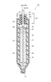
図1は、本発明の電力貯蔵デバイスの好適な実施形態を示す斜視図であり、電力貯蔵デバイスとしての非水電解質電池を示している。本実施形態の非水電解質電池10は、図1に示すように薄肉形となっており、非水電解質電池10は、非水の溶媒(例えば有機溶媒)に電解質(例えばフッ化リチウム化合物)が溶解された非水電解液(電解質媒体)を含む単一の電気化学セルを、周縁部が熱融着されてヒートシールされる部分12が形成された封入袋14に封入することにより構成されている。この非水電解質電池10においては、正極用リード18a、負極用リード18bの一端が封入袋14の上部から上方に延び、外部との電気的な接続を可能にしている。なお、正極用リード18a、負極用リード18bはそれぞれ、封入袋14の内部から外部までのびるリード導体19を有しており、それらの外周にはそれぞれ絶縁体21が被覆されている。ここで、封入袋14及び絶縁体21が絶縁体付の封入袋114を構成し、絶縁体付の封入袋114が第一袋体に対応する。また、封入袋14が第二袋体に対応する。
【0025】
図2は、図1の非水電解質電池10のII−II線に沿った矢視図である。図2に示すように、この封入袋14は、非水電解液20の浸透を抑制する観点から、例えばアルミニウムからなる金属箔又は金属層22をプラスチック層からなる層24,28が挟持することにより形成された多層フィルムからなっている。
【0026】
より詳細に述べると、封入袋14は、非水電解液20と接触する上記多層フィルムの最も内側の層24の周縁部を熱融着することにより形成されている。ここで、最も内側の層24は、この内側層24の周縁部に形成されるヒートシール部分12における非水電解液20の漏出を防止する観点から、例えばマレイン酸変性ポリオレフィン(例えばマレイン酸変性低密度ポリエチレン)からなり、封入袋14の最も外側の層28は、金属層22を外傷から保護するために設けられ、例えばPET(ポリエチレンテレフタレート)からなる。
【0027】
また、封入袋14内に収容される非水電解液20としては、例えばプロピレンカーボネート、γ−ブチロラクトン等の有機溶媒に、LiBF4、LiPF6、LiAsF6のようなフッ化リチウム化合物からなる溶質を溶解したものが用いられる。さらに、封入袋14内には、非水電解液20に浸される正極板(正極)30と負極板(負極)32が封入され、これら正極板30及び負極板32は、集電体と呼ばれる金属箔又はエキスパンデッドメタルの金属基材(図示せず)と、金属基材上に形成された活物質層(図示せず)とからなる。また、正極板30と負極板32との間には、非水電解液20の拡散を防止するためのセパレータ34が配置されている。
【0028】
さらに、正極板30の金属基材は、導線36を介して正極用リード18aのリード導体19の一端に接続され、リード導体19の他端は封入袋14の外部に延びている。負極板32の金属基材も、負極用リード18bのリード導体19の一端に導線38を介して接続され、そのリード導体19の他端は封入袋14の外部に延びている。また、正極用リード18aのリード導体19の一部及び負極用リード18bのリード導体19の一部はそれぞれ絶縁体21と溶着することによって被覆されている。そして、正極用リード18a及び負極用リード18bは、各々の絶縁体21が封入袋14の最も内側の層24と熱融着されることによって封入袋14に取り付けられている。
【0029】
ここで、正極用リード18a、負極用リード18bについて詳細に説明する。
【0030】
図3は正極用リード18a,負極用リード18bの一部破断斜視図である。本実施形態に係る正極用リード18a、負極用リード18bは、所定長さの矩形板状の電気導電体であるリード導体19と、このリード導体19の長さ方向ほぼ中央部の外周を取り囲むように融着されて被覆する絶縁体21を有している。ここで、リード導体19の長さ方向は、上述の非水電解質電池10においてリード導体19が封入袋14の内部から外部に延びる方向に対応する。
【0031】
そして、本実施形態に係る正極用リード18a、負極用リード18bにおいて、リード導体19における絶縁体21が被覆される部分の表面に、このリード導体19の長さ方向に直交する方向に延びる複数の溝120が形成されている。
【0032】
この溝120は、リード導体19の長さ方向に互いに離間されて形成されている。この溝120の深さは、導体の厚さに対して1〜20%とすることが好ましく、5〜15%とすることがより好ましい。また、この溝120の開口幅は、2〜500μmとすることが好ましく、5〜50μmとすることがより好ましい。さらに、溝120の間隔は、例えば、0.1〜1.0mm程度である。
【0033】
さらに、この溝120は、リード導体19の両方の主表面19a、19bに各々形成されている。そして、溝120は、各々の主表面19aの一方の縁から他方の縁までに亘って連続して形成されている。また、溝120の断面形状は、例えば、矩形である。
【0034】
正極用リード18a用のリード導体19の材料としては、例えば、アルミニウムや、ステンレスを利用できる。
【0035】
例えば、アルミニウムを用いる場合には、アルミニウムの純度を97%以上とすることが好ましい。アルミニウムの純度が97%未満では、不純物が非水電解質電池10の性能に悪影響を与えることとなる場合がある。
【0036】
また、負極用リード18bのリード導体19の材料としては、過充電時にリチウム等の析出物が生じたり、又は電位差が大きくなる過放電時にはリチウム合金等を形成し難く且つ溶解しにくいもの、例えばニッケル、銅、あるいは、ステンレス、又は、これらの合金からなるものを利用できる。これらの合金としては、例えば、ニッケルメッキ銅が挙げられる。
【0037】
絶縁体21は、リード導体19の外周に熱融着される熱可塑層23を有する。この熱可塑層23は、溝120内に食い込むようにしてリード導体19の外周を被覆しシールしている。
【0038】
この熱可塑層23は、例えば、熱可塑性ポリオレフィン樹脂を利用できる。このような熱可塑性ポリオレフィン樹脂としては、リード導体19に接着可能なものが用いられ、このうち、加熱により溶融してリード導体19に対してより融着しやすくなることから、ポリエチレン、酸変性ポリエチレン、ポリプロピレン、エチレン酢酸ビニル共重合体、酸変性ポリプロピレン(例えば無水マレイン酸変性ポリプロピレン)、アイオノマー等の反応性樹脂又はこれらの混合物が好ましい。ここで、封入袋14の最も内側の層24を構成する材料として耐熱性に優れるポリプロピレンが用いられる場合には、上記の熱可塑性ポリオレフィン樹脂のうちポリプロピレン又は酸変性ポリプロピレンを用いることが好ましい。この場合、熱可塑性ポリオレフィン樹脂としてポリエチレンやエチレン酢酸ビニル共重合体を用いる場合に比べて、絶縁体21と封入袋14の最も内面の層24との接着性を高め、非水電解質電池10に高い耐熱性を付与することが可能となる。なお、上記のアイオノマーとしては、ポリエチレン、ポリプレピレン等の単独重合体若しくはエチレンとメタクリル酸等の共重合体をNa、Mg、K等で架橋させたものが用いられる。
【0039】
また、絶縁体21は、熱可塑層23の外側に架橋層25を含む。架橋層25としては、架橋されたポリオレフィン樹脂を利用できる。ポリオレフィン樹脂は、封入袋14の最も内側の層24と熱融着可能であるものであればよいが、上述の熱可塑性ポリオレフィン樹脂と同じ樹脂が用いられることが好ましい。これは、上述の熱可塑性ポリオレフィン樹脂と異なる樹脂が用いられると、熱可塑層23と架橋層25との間の接着力が低下する傾向があるからである。
【0040】
ここで、封入袋14の最も内側の層24を構成する材料として耐熱性に優れるポリプロピレンが用いられる場合には、上記のポリオレフィン樹脂としてポリプロピレン又は酸変性ポリプロピレンが用いられることが好ましい。この場合、上記ポリオレフィン樹脂としてポリエチレンやエチレン酢酸ビニル共重合体を用いる場合に比べ、絶縁体21と封入袋14の最も内面の層24との接着性、及び非水電解質電池10の耐熱性が一層向上することになる。
【0041】
ポリオレフィン樹脂を架橋する方法としては、電子線やガンマ線等の電離放射線の照射による架橋、パーオキサイド等による化学架橋、シラン架橋等が用いられる。上記ポリオレフィン樹脂を電離放射線によって架橋する場合、必要に応じてポリオレフィン樹脂に架橋助剤が添加される。この架橋助剤としては、例えばトリメチロールプロパンメタクリレート、ペンタエリスリトールトリアクリレート、エチングリコールジメタクリレート、トリアリルシアヌレート、トリアリルイソシアヌレート等が用いられる。
【0042】
架橋されたポリオレフィン樹脂は、その融点以上に加熱されても耐熱変形性に優れ、また、リード18a,18bの絶縁体21を封入袋14の内面と熱融着させるときでも、リード導体19と封入袋14の金属層22との間のショートを十分に防止することが可能となる。
【0043】
また、架橋ポリオレフィン樹脂においては、そのゲル分率が20%〜90%であることが好ましい。ゲル分率は、架橋の度合いを示す指標であり、キシレン等の溶媒に不溶になった架橋ポリオレフィン樹脂中のゲル(不溶になった高分子鎖)の割合をいう。ゲル分率が20%未満では、架橋の度合いが不十分であり、封入袋14の内面と架橋層25とを熱融着するときに封入袋14の金属層22とリード導体19とがショートしやすい傾向がある。一方、ゲル分率が90%を超えると、架橋の度合いが大きすぎ、封入袋14と架橋層25との間の接着性が悪くなり、非水電解液20が漏出しやすい傾向がある。
【0044】
なお、負極用リード18bのリード導体19に被覆された絶縁体21も熱可塑層23と架橋層25を備えており、熱可塑層23を構成する熱可塑性ポリオレフィン樹脂、架橋層25を構成する架橋ポリオレフィン樹脂としてはそれぞれ、正極用リード18aのリード導体19において用いられる熱可塑性ポリオレフィン樹脂、及び架橋ポリオレフィン樹脂を用いることができる。
【0045】
上記非水電解質電池10によれば、リード導体19における絶縁体21に被覆された部分に、リード導体19が内部から外部まで延びる方向に対して直交する方向に延びる溝120が形成されている。このため、リード導体19と絶縁体21との間において、リード導体19が延びる方向に沿う水分やフッ化物等の物質の移動が十分に抑制される。これにより、このリード導体19と絶縁体21との間におけるリード導体19の腐食が十分に防止される。従って、リード導体19からの絶縁体21の剥離を長期間にわたって十分に防止できる。特に、電解質にフッ化物を有する場合には、フッ化物と水との反応によって生成されるフッ酸等の腐食物の生成も低減されて効果が高い。
【0046】
また、絶縁体21の熱可塑層23が溝120内に食い込んでいるので、アンカー効果によって、リード導体から絶縁体21が剥離されにくくなっている。
【0047】
従って、非水電解液の漏出による電池10の性能劣化が十分に防止されると共に、封入袋14の外部に漏出するフッ酸により外部機器が腐食されることが十分に防止される。
【0048】
ここで、溝120の断面形状は、特に限定されず、矩形断面以外に、例えば、V字状、U字状等の断面形状の溝の適用が考えられる。
【0049】
また、溝120は、リード導体19の側面19c,19dに形成されていてもよい。
また、溝120は、必ずしもリード導体19の一方の縁から他方の縁まで延在していなくてもよい。
【0050】
つぎに、電池10の製造方法について説明する。まず、第一の製造方法について説明する。ここでは、まず、リード導体19及び正極用リード18aの製造方法について説明する。
【0051】
はじめに、図4(a)に示すように、正極用リード18aのリード導体19として、矩形の平板状の所定長さのアルミニウム板を用意する。そして、このリード導体19の表裏面の一部に、図4(b)に示すように、幅方向に延びる溝120を形成する。この溝120は、その表面に、リード導体19の長さ方向に直交する向きの突条205が形成された金型でリード導体19をプレスすることにより形成する。
【0052】
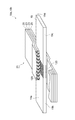
一方、図5(a)に示すように、例えば無水マレイン酸変性低密度ポリエチレン等のポリオレフィン樹脂からなる熱可塑性の熱可塑性フィルム23Aと、例えば低密度ポリエチレン等のポリオレフィン樹脂からなり架橋層を形成可能な熱可塑性フィルム25AをそれぞれTダイやインフレーション押出機で作製する。そして、図5(b)に示すように、熱可塑性フィルム25Aに対しては架橋処理を行って、架橋された熱可塑性フィルム25Bを作成する。架橋処理の方法としては、γ線や電子線等の電離放射線による照射架橋、パーオキサイド等による化学架橋、シラン架橋等が用いられるが、生産性を向上させる観点からは、短時間で架橋させることが可能な照射架橋が最も好ましい。そして、こうして得られた架橋された熱可塑性フィルム25Bと、上述の熱可塑性フィルム23Aとを、図5(c)に示すようにそれぞれ熱ラミネートにより貼りあわせて、熱可塑層23と、架橋層25の2層からなる絶縁体21を得る。
【0053】
つぎに、こうして得られる絶縁体21を2枚用意し、図6に示すように、それぞれの熱可塑層23をリード導体19に向けてリード導体19を挟む。その後、絶縁体21を加熱して絶縁体21の熱可塑層23とリード導体19とを熱融着させる。こうして、図7に示すような正極用リード18aが得られる。
【0054】
負極用リード18bも、上述した方法と同様の方法で作製される。ただし、負極用リード18bのリード導体19は、正極用リード18aのリード導体19に用いられる材料であってもよいが、銅、ニッケル、ステンレス、又は、ニッケルメッキ銅等のこれらの合金からなるものを用いることが好ましい。
【0055】
なお、リード18a,18bの作製方法は、上述した方法に限定されるものではない。例えば、ポリオレフィン樹脂からなる1層の熱可塑性フィルムを用意し、この熱可塑性フィルムをリード導体19に熱融着させた後、この熱可塑性フィルムの外側から、透過距離がフィルムの厚さよりも小さくなるように制御した電子線を照射することによってもリード18a,18bを得ることができる。この場合、熱可塑性フィルムのうち電子線があたった部分が架橋層25となり、電子線があたらなかった部分は熱可塑層23となる。
【0056】
このような製造方法によれば、上述の如き溝120が形成されたリード導体19、リード18a、18aが好適に形成できる。さらに、プレスにより溝120を形成しているので、大量生産に好適であって低コストでの生産が可能である。
【0057】
つぎに、上述した正極用リード18a及び負極用リード18bを封入袋14に取り付ける方法の一例について説明する。
【0058】
正極用リード18a及び負極用リード18bが取り付けられる封入袋14は、以下のようにして作製される。すなわち、まず、表面にマレイン酸変性ポリオレフィンからなる層を含み、且つ内部に金属箔又は金属層を含む矩形状の多層フィルムを一対用意する。つぎに、マレイン酸変性ポリオレフィンの層が対向するようにこれら多層フィルムを重ねあわせ、矩形の周囲の2辺を、シール機を用いて所定の加熱条件で所望のシール幅だけヒートシールする。こうして2辺(図示上方側及び紙面に垂直な方向側)に開口を有する封入袋14が得られる(図8(a)参照)。
【0059】
このような封入袋14に対して、正極用リード18a及び負極用リード18bの一部を封入袋14の上部の開口を通して封入袋14内に収容する。このとき、正極用リード18aの絶縁体21、負極用リード18bの絶縁体21がそれぞれ封入袋14の最も内側の層24の間に配置されるように収容する。そして、リード導体19,19と正極板30,負極板32とを各々接続した後、絶縁体21を、封入袋14の開口端部によって挟み込み、シール機を用いて絶縁体21の架橋層25と封入袋14の最も内側の層24とを熱融着させる(図8(b)参照)。ここでは、リード導体19の長さ方向の一端が封入袋14の内部から外部に突出する状態で、溝120を被覆する絶縁体21が封入袋14のもっとも内側の層24に融着される。
【0060】
このとき、絶縁体21には架橋層25が含まれており、絶縁体21における架橋層25の融点は熱可塑層23よりも低く、架橋層25は熱可塑層23に比して溶融しにくくなっているので、熱融着時の加熱によってリード導体19と封入袋14の金属層22との間のショートが十分に防止される。
【0061】
続いて、残りの開口部から封入袋14内に非水電解液20を投入すると共に、内部を減圧して開口を熱シールし、図1のような非水電解質電池が得られる。
【0062】
次に、本実施形態にかかる他の電池の製造方法について説明する。本実施形態において、上述の製造方法と異なる点は、あらかじめ、絶縁体21を封入袋14の内面に融着して絶縁体付の封入袋(第一袋体)114を形成し(図9(a)参照)、溝120が形成される一方絶縁体21が融着されていない図4(b)の状態のリード導体19を、図9(a)に示すように絶縁体付の封入袋114内に挿入し、絶縁体付きの封入袋114内の絶縁体21の熱可塑層23に融着させる点である(図9(b)参照)。ここでは、リード導体19の長さ方向の一端が封入袋14の内部から外部に突出する状態で、リード導体19における溝120が形成された部分が封入袋14のもっとも内側の層24に融着される。これによっても上述と同様の電池が製造でき、同様の作用効果を有する。
【0063】
ここで、本発明は、上記実施形態に限定されない。例えば上記実施形態では、電力貯蔵デバイスとして、非水電解質電池10が用いられているが、水溶液中に電解質が溶解した水系電解質電池を用いてもよい。さらに、電解質電池に代えてキャパシタが用いられても良い。この場合、正極板30及び負極板32のそれぞれにおいて固体活性炭を用いる必要がある。また、キャパシタが用いられる場合は、負極用リード18bのリード導体19としてアルミニウムを用いることが好ましい。
【0064】
以下、本発明の内容を、実施例を用いてより具体的に説明する。
(実施例1)
まず、リード導体19として、厚さが0.1mmで幅が5mm、長さが50mmの銅板を用意した。そして、このリード導体19の表裏面に、プレスにより溝120を形成した。ここで、溝120の深さは10μm、断面形状はほぼ矩形、溝120の間隔は0.5mm間隔とし、溝120はリード導体19の表面の一方の縁から他方の縁まで延びるように形成され、溝120を10本形成した。
【0065】
一方、厚さが50μmの無水マレイン酸変性低密度ポリエチレンフィルム(密度:0.92g/cm3、メルトフローレート(MFR):1.0g/10min、融点:123℃)と、厚さが50μmの低密度ポリエチレンフィルム(密度:0.92g/cm3、MFR:1.0g/10min、融点:123℃)とを用意し、そのうちの低密度ポリエチレンフィルムについては、電子線照射装置を用いて、加速電圧200kVの電子線を吸収線量が30kGyとなるように照射して架橋させた。また、上記無水マレイン酸変性低密度ポリエチレンフィルム及び低密度ポリエチレンフィルムのMFRは、JISK−6760(試験温度:190℃、負荷:21.17N)に従って測定した。
【0066】
そして、無水マレイン酸変性低密度ポリエチレンフィルムと、低密度ポリエチレンフィルムとを150℃で熱ラミネートすることによって貼りあわせた。つぎに、このラミネートフィルムを切断して7mm×15mmの正方形の絶縁体21を2枚得た。
【0067】
その後、2枚の絶縁体21がリード導体19を介して対向するように重ね合わせ、この状態で、150℃×10秒の熱プレスにより絶縁体21をリード導体19で溝120が形成された部分に熱融着させ、その後、導体幅方向の絶縁長が9mmとなるように切断して、負極用リード18bを形成した。
【0068】
こうして得られた負極用リード18bを、炭酸エチレン(Ethylene carbonate, EC):炭酸ジエチル(Diethyl carbonate, DEC):炭酸ジメチル(Dimethyl carbonate, DMC)=1:1:1で、かつフッ化リチウム化合物を含む電解液中に浸漬し、剥がれるまでの時間を観察した。その結果、168時間経過してもリード導体19からの絶縁体21の剥離は見られなかった。
【0069】
(比較例1)
リード導体19に溝120を形成しないこと以外は、実施例1と同様にして負極用リードを得た。そして、実施例1と同様に、負極用リードを電解液中に浸漬した。その結果、3hでリード導体から絶縁体が剥離した。
【0070】
【発明の効果】
以上説明したように本発明によれば、リード導体からの絶縁体の剥離を長期間にわたって十分に、かつ、低コストに防止できる。従って、電解液の漏出が十分に抑制され、電池の性能の劣化、外部の機器の腐食を十分に低減することができる。
【図面の簡単な説明】
【図1】図1は、本発明の電力貯蔵デバイスの一実施形態を示す斜視図である。
【図2】図2は、図1のII−II線に沿った矢視図である。
【図3】図3は、本発明のリードの一実施形態を示す斜視図である。
【図4】図4(a)は、リードの製造方法を説明する斜視図、図4(b)はリードの製造方法を説明する図4(a)に続く斜視図である。
【図5】図5(a)、図5(b)、図5(c)は、リードの製造方法を説明する図4(b)に続く模式図である。
【図6】図6は、リードの製造方法を説明する図5に続く斜視図である。
【図7】図7は、リードの製造方法を説明する図6に続く斜視図である。
【図8】図8(a)は、非水電解質電池の製造方法を説明する模式図、図8(b)は、図8(a)に続く非水電解質電池の製造方法を説明する模式図である。
【図9】図9(a)は、非水電解質電池の他の製造方法を説明する模式図、図9(b)は、図9(a)に続く非水電解質電池の他の製造方法を説明する模式図である。
【符号の説明】
10…非水電解質電池、14…封入袋(第二袋体)、18a…正極用リード、18b…負極用リード、19…リード導体、20…非水電解液(電解質媒体)、21…絶縁体、22…金属層、23…熱可塑層、25…架橋層、30…正極板(正極)、32…負極板(負極)、114…絶縁体付の封入袋(第一袋体)、120…溝。[0001]
BACKGROUND OF THE INVENTION
The present invention relates to an electrolyte battery used as a power source for electronic equipment and the like, a power storage device such as a capacitor, a lead conductor used therefor, a lead, and a method for manufacturing the same, and more specifically, a positive electrode, a negative electrode, an electrolyte medium, and the like. The present invention relates to a power storage device including a bag body to be sealed, a lead conductor used in the power storage device, a lead, and a method of manufacturing the lead conductor.
[0002]
[Prior art]
In accordance with the demand for downsizing of electronic devices, there is an increasing demand for downsizing and weight reduction of batteries used as power sources. On the other hand, higher energy density and higher energy efficiency for batteries are also required. In order to satisfy such a demand, an electrolyte battery (for example, a non-aqueous electrolyte battery such as a Li ion battery or a lithium polymer battery) in which a positive electrode, a negative electrode, an electrolytic solution, etc. are sealed inside a bag made mainly of a synthetic resin or the like is used. Expectations are rising.
[0003]
In such an electrolyte battery, in general, a lead conductor extends from the inside of the bag body to the outside in order to extract current from the positive electrode and the negative electrode to the outside. The lead conductors for the positive electrode and the negative electrode are sealed by heat-sealing with the insulator on the inner surface of the bag body.
[0004]
In the conventional electrolyte battery, the insulator may be peeled off from the lead conductor while being repeatedly charged and discharged over a long period of time. For example, when the lead conductor / insulator combination is a metal / ionomer, metal / modified polypropylene, or the like, and the electrolyte contains a chlorine or fluorine-containing lithium salt, the lead conductor / insulation is performed at a high temperature of 60 ° C. or higher. The adhesive force at the interface of the body is reduced, and the lead conductor and the insulator are easily separated at the interface. And it has become clear that the penetration of moisture, oxygen, etc. from the outside into the battery through this peeling part is promoted and the battery performance is lowered.
[0005]
And in order to prevent the peeling of the insulator from such a lead conductor, for example, a method of performing alumite treatment or boehmite treatment on the lead conductor (see Patent Document 1), dry blast treatment, wet blast treatment on the lead conductor, A method of performing mechanical rough surface processing such as embossing processing (see Patent Document 2) is known.
[0006]
[Patent Document 1]
JP 2000-149913 A
[Patent Document 2]
JP 2000-149914 A
[0007]
[Problems to be solved by the invention]
However, in the method of performing alumite treatment or boehmite treatment, it is necessary to perform the treatment only on the portion of the lead conductor that is covered with the insulator. It becomes. On the other hand, the mechanical surface roughening method such as the blast method is not sufficient in preventing the peeling of the insulator from the lead conductor.
[0008]
The present invention has been made in view of the above circumstances, can reduce the cost, and can sufficiently prevent the peeling of the insulator from the lead conductor over a long period of time. Ru Lead, power storage device using the same , And it aims at providing the manufacturing method of a lead.
[0009]
[Means for Solving the Problems]
The inventors of the present invention have studied the problems of the above prior art. As a result, it has been found that movement of substances such as moisture from the outside to the inside of the bag body and movement of electrolytes such as fluorine compounds from the inside of the bag body to the outside occur between the lead conductor and the insulator. And it discovered that a lead conductor was corroded by these substances moving between a lead conductor and an insulator, and an insulator became easy to peel from a lead conductor. In particular, in a non-aqueous electrolyte battery using a non-aqueous electrolyte medium, moisture and a fluorine compound in the non-aqueous electrolyte react with each other to generate a corrosive substance such as hydrofluoric acid, and the tendency of such corrosion is remarkable.
[0011]
Therefore, The lead according to the present invention encloses an electrolyte medium, a positive electrode, and a negative electrode Bag (second bag) Lead conductors projecting from the inside to the outside, and covering the lead conductors bag Inside End of An insulator fused to the lead, The lead conductor is a plate, Lead conductor Both main faces In the surface of the portion covered with the insulator in FIG. 1, there is a groove extending in the direction intersecting the direction in which the lead conductor protrudes. Respectively Is formed.
[0012]
The power storage device according to the present invention is Bag (second bag) When, An insulator fused to the inner edge of the bag and , bag Electrolyte medium, positive and negative electrodes, and insulator Covered Is bag Protruding from inside to outside Is Lead conductor for positive electrode and insulator Covered Is bag In a power storage device comprising a negative electrode lead conductor protruding from the inside to the outside, At least one of the lead conductor for positive electrode and the lead conductor for negative electrode is a plate-like body, At least one of a positive lead conductor and a negative lead conductor Both main faces In the portion fused with the insulator, a groove extending in a direction intersecting the direction in which the lead conductor protrudes is formed. Respectively Is formed.
[0013]
According to these inventions, the lead conductor is formed on the portion of the lead conductor covered with the insulator. bag A groove extending in a direction intersecting with the direction extending from the inside to the outside of the substrate is formed. This sufficiently suppresses movement of substances such as moisture and electrolyte medium along the direction in which the lead conductor protrudes between the lead conductor and the insulator. For this reason, corrosion of the lead conductor between the lead conductor and the insulator is sufficiently suppressed. Therefore, peeling of the insulator from the lead conductor is sufficiently prevented over a long period of time. In addition, since such a groove can be easily formed by pressing or the like, it can be realized at a low cost.
[0014]
here, On both sides, It is preferable that a plurality of grooves are formed apart from each other, thereby further restricting the movement of the substance between the lead conductor and the insulator.
[0015]
The lead conductor is a plate-like body. R , Forming grooves on both sides of the plate Because As a result, the peeling of the insulator can be effectively suppressed.
[0016]
The insulator preferably includes at least two layers having different deformation amounts when heated, whereby the lead has a metal layer. bag The possibility of a short circuit between the lead conductor and the metal layer can be reduced.
[0017]
In addition, one of the two layers of the insulator is preferably a layer crosslinked by electron beam irradiation, thereby suitably forming a layer with less deformation than the other layer. it can.
[0018]
Alternatively, one of the two layers of the insulator may have a higher melting point than that of the other layer, and accordingly, a layer having a smaller amount of deformation than the other layer is preferably used. Can be formed.
[0020]
In the lead conductor manufacturing method according to the present invention, the electrolyte medium, the positive electrode, and the negative electrode are enclosed. Bag (second bag) Lead conductors projecting from the inside to the outside, and covering the lead conductors bag An insulator fused to the inner surface of the lead, comprising: It is a plate-like body Lead conductor Both lords A groove extending in the direction intersecting the direction in which the lead conductor protrudes is formed on the surface. Respectively And a step of covering the portion of the lead conductor where the groove is formed with an insulator.
[0021]
According to such a manufacturing method, as described above. Ki A lead can be suitably manufactured.
[0022]
Here, it is preferable to form a groove by pressing. According to this, since a groove can be easily formed, mass production can be performed at low cost.
[0023]
DETAILED DESCRIPTION OF THE INVENTION
Hereinafter, embodiments of the present invention will be described in detail with reference to the accompanying drawings. In the drawings, the same or equivalent components are denoted by the same reference numerals.
[0024]
FIG. 1 is a perspective view showing a preferred embodiment of the power storage device of the present invention, and shows a nonaqueous electrolyte battery as the power storage device. The
[0025]
FIG. 2 is a view taken along the line II-II of the
[0026]
More specifically, the encapsulating
[0027]
Moreover, as the
[0028]
Further, the metal base material of the
[0029]
Here, the
[0030]
FIG. 3 is a partially broken perspective view of the
[0031]
And in the lead 18a for positive electrodes and the lead 18b for negative electrodes which concern on this embodiment, on the surface of the part which the
[0032]
The
[0033]
Further, the
[0034]
As the material of the
[0035]
For example, when aluminum is used, the purity of aluminum is preferably 97% or more. If the purity of aluminum is less than 97%, impurities may adversely affect the performance of the
[0036]
Further, the material of the
[0037]
The
[0038]
The
[0039]
The
[0040]
Here, when polypropylene having excellent heat resistance is used as the material constituting the
[0041]
As a method for crosslinking the polyolefin resin, crosslinking by irradiation with ionizing radiation such as electron beam or gamma ray, chemical crosslinking with peroxide, silane crosslinking, or the like is used. When the polyolefin resin is crosslinked by ionizing radiation, a crosslinking aid is added to the polyolefin resin as necessary. Examples of the crosslinking aid include trimethylolpropane methacrylate, pentaerythritol triacrylate, ethyne glycol dimethacrylate, triallyl cyanurate, triallyl isocyanurate, and the like.
[0042]
The cross-linked polyolefin resin is excellent in heat-resistant deformation even when heated above its melting point, and when the
[0043]
Moreover, in crosslinked polyolefin resin, it is preferable that the gel fraction is 20%-90%. The gel fraction is an index indicating the degree of crosslinking and refers to the ratio of gel (insoluble polymer chain) in the crosslinked polyolefin resin that has become insoluble in a solvent such as xylene. If the gel fraction is less than 20%, the degree of crosslinking is insufficient, and the
[0044]
The
[0045]
According to the
[0046]
In addition, since the
[0047]
Therefore, the performance deterioration of the
[0048]
Here, the cross-sectional shape of the
[0049]
Further, the
Further, the
[0050]
Next, a method for manufacturing the
[0051]
First, as shown in FIG. 4A, a rectangular flat aluminum plate having a predetermined length is prepared as the
[0052]
On the other hand, as shown in FIG. 5 (a), for example, a
[0053]
Next, two
[0054]
The
[0055]
The manufacturing method of the
[0056]
According to such a manufacturing method, the
[0057]
Next, an example of a method for attaching the
[0058]
The encapsulating
[0059]
Part of the
[0060]
At this time, the
[0061]
Subsequently, the
[0062]
Next, another battery manufacturing method according to this embodiment will be described. In the present embodiment, the difference from the manufacturing method described above is that the
[0063]
Here, the present invention is not limited to the above embodiment. For example, in the above embodiment, the
[0064]
Hereinafter, the contents of the present invention will be described more specifically with reference to examples.
Example 1
First, a copper plate having a thickness of 0.1 mm, a width of 5 mm, and a length of 50 mm was prepared as the
[0065]
On the other hand, a maleic anhydride-modified low-density polyethylene film having a thickness of 50 μm (density: 0.92 g / cm Three , Melt flow rate (MFR): 1.0 g / 10 min, melting point: 123 ° C., and a low-density polyethylene film having a thickness of 50 μm (density: 0.92 g / cm) Three , MFR: 1.0 g / 10 min, melting point: 123 ° C.), and for the low density polyethylene film, an electron beam irradiation device is used so that the absorbed dose of an electron beam with an acceleration voltage of 200 kV is 30 kGy. Were cross-linked by irradiation. The MFR of the maleic anhydride-modified low density polyethylene film and the low density polyethylene film was measured according to JISK-6760 (test temperature: 190 ° C., load: 21.17 N).
[0066]
Then, the maleic anhydride-modified low density polyethylene film and the low density polyethylene film were bonded together by heat laminating at 150 ° C. Next, the laminate film was cut to obtain two 7 mm × 15 mm
[0067]
Thereafter, the two
[0068]
The
[0069]
(Comparative Example 1)
A negative electrode lead was obtained in the same manner as in Example 1 except that the
[0070]
【The invention's effect】
As described above, according to the present invention, it is possible to sufficiently prevent the insulator from being peeled off from the lead conductor for a long period of time at a low cost. Accordingly, leakage of the electrolytic solution is sufficiently suppressed, and deterioration of battery performance and corrosion of external equipment can be sufficiently reduced.
[Brief description of the drawings]
FIG. 1 is a perspective view showing an embodiment of a power storage device of the present invention.
FIG. 2 is a view taken along the line II-II in FIG. 1;
FIG. 3 is a perspective view showing an embodiment of the lead of the present invention.
4A is a perspective view for explaining a lead manufacturing method, and FIG. 4B is a perspective view following FIG. 4A for explaining a lead manufacturing method.
FIG. 5A, FIG. 5B, and FIG. 5C are schematic views subsequent to FIG. 4B for explaining a lead manufacturing method.
FIG. 6 is a perspective view subsequent to FIG. 5 for explaining the lead manufacturing method;
7 is a perspective view subsequent to FIG. 6 for explaining the lead manufacturing method; FIG.
8A is a schematic diagram for explaining a method for manufacturing a nonaqueous electrolyte battery, and FIG. 8B is a schematic diagram for explaining a method for manufacturing a nonaqueous electrolyte battery following FIG. 8A. It is.
9A is a schematic diagram illustrating another method for manufacturing a non-aqueous electrolyte battery, and FIG. 9B illustrates another method for manufacturing the non-aqueous electrolyte battery subsequent to FIG. 9A. It is a schematic diagram to explain.
[Explanation of symbols]
DESCRIPTION OF
Claims (7)
前記リード導体は板状体であり、前記リード導体の両主面において前記絶縁体に被覆された部分の表面には、前記リード導体が突出する方向に対して交差する方向に延びる複数の溝がそれぞれ形成され、
前記溝の深さは、前記リード導体の厚さに対して5〜15%であり、前記溝の開口幅は2〜500μmであり、前記溝の間隔は0.1〜1.0mmであるリード。A lead comprising an electrolyte medium, a positive electrode, and a lead conductor protruding from the inside of the bag in which the negative electrode is sealed to the outside, and an insulator covering the lead conductor and fused to the end of the inner surface of the bag Because
The lead conductor is a plate-like body, and a plurality of grooves extending in a direction intersecting with the direction in which the lead conductor protrudes are formed on the surface of the portion covered with the insulator on both main surfaces of the lead conductor. Each formed ,
The depth of the groove is 5 to 15% with respect to the thickness of the lead conductor, the opening width of the groove is 2 to 500 μm, and the distance between the grooves is 0.1 to 1.0 mm. .
前記袋の内面の端部に融着された絶縁体と、
前記袋の内部に封入された電解質媒体、正極、及び、負極と、
前記絶縁体に被覆され前記袋の内部から外部まで突出する正極用リード導体と、
前記絶縁体に被覆され前記袋の内部から外部まで突出する負極用リード導体と、を備え、
前記正極用リード導体及び前記負極用リード導体の少なくとも一方は板状体であり、前記正極用リード導体及び前記負極用リード導体の前記少なくとも一方の両主面における、前記絶縁体に被覆された部分には、前記リード導体が突出する方向に対して交差する方向に延びる複数の溝がそれぞれ形成され、前記溝の深さは、前記リード導体の厚さに対して5〜15%であり、前記溝の開口幅は2〜500μmであり、前記溝の間隔は0.1〜1.0mmである電力貯蔵デバイス。A bag,
An insulator fused to an end of the inner surface of the bag;
An electrolyte medium enclosed in the bag, a positive electrode, and a negative electrode;
A lead conductor for a positive electrode which is covered with the insulator and protrudes from the inside of the bag to the outside;
A negative electrode lead conductor covered with the insulator and protruding from the inside of the bag to the outside,
At least one of the positive electrode lead conductor and the negative electrode lead conductor is a plate-like body, and is a portion covered with the insulator on both main surfaces of the positive electrode lead conductor and the negative electrode lead conductor. Are formed with a plurality of grooves extending in a direction intersecting the direction in which the lead conductor protrudes, and the depth of the groove is 5 to 15% with respect to the thickness of the lead conductor, The power storage device , wherein an opening width of the grooves is 2 to 500 μm, and an interval between the grooves is 0.1 to 1.0 mm .
板状体であるリード導体の両主面に、前記リード導体が突出される方向に対して交差する方向に延びる複数の溝をそれぞれ形成する工程と、
前記リード導体において溝が形成された部分に絶縁体を被覆する工程と、
を含み、前記溝の深さは、前記リード導体の厚さに対して5〜15%であり、前記溝の開口幅は2〜500μmであり、前記溝の間隔は0.1〜1.0mmであるリードの製造方法。A lead provided with an electrolyte medium, a positive electrode, and a lead conductor that protrudes from the inside of the bag in which the negative electrode is sealed to the outside, and an insulator that covers the lead conductor and is fused to the end of the inner surface of the bag A manufacturing method of
Forming each of a plurality of grooves extending in a direction intersecting the direction in which the lead conductor protrudes on both main surfaces of the lead conductor which is a plate-like body;
Coating the insulator on the portion where the groove is formed in the lead conductor;
The depth of the groove is 5 to 15% with respect to the thickness of the lead conductor, the opening width of the groove is 2 to 500 μm, and the interval between the grooves is 0.1 to 1.0 mm. A method for manufacturing a lead.
Priority Applications (1)
| Application Number | Priority Date | Filing Date | Title |
|---|---|---|---|
| JP2003159813A JP4677708B2 (en) | 2003-06-04 | 2003-06-04 | Lead, power storage device, and lead manufacturing method |
Applications Claiming Priority (1)
| Application Number | Priority Date | Filing Date | Title |
|---|---|---|---|
| JP2003159813A JP4677708B2 (en) | 2003-06-04 | 2003-06-04 | Lead, power storage device, and lead manufacturing method |
Publications (2)
| Publication Number | Publication Date |
|---|---|
| JP2004362935A JP2004362935A (en) | 2004-12-24 |
| JP4677708B2 true JP4677708B2 (en) | 2011-04-27 |
Family
ID=34052784
Family Applications (1)
| Application Number | Title | Priority Date | Filing Date |
|---|---|---|---|
| JP2003159813A Expired - Fee Related JP4677708B2 (en) | 2003-06-04 | 2003-06-04 | Lead, power storage device, and lead manufacturing method |
Country Status (1)
| Country | Link |
|---|---|
| JP (1) | JP4677708B2 (en) |
Cited By (1)
| Publication number | Priority date | Publication date | Assignee | Title |
|---|---|---|---|---|
| KR20160007474A (en) | 2013-05-08 | 2016-01-20 | 스미토모 덴키 고교 가부시키가이샤 | Lead conductor and electrical energy storage device |
Families Citing this family (22)
| Publication number | Priority date | Publication date | Assignee | Title |
|---|---|---|---|---|
| BRPI0606460B1 (en) * | 2005-01-21 | 2018-06-12 | Lg Chem, Ltd. | “Secondary Battery” |
| JP2008186779A (en) * | 2007-01-31 | 2008-08-14 | Toshiba Corp | Nonaqueous electrolyte battery |
| JP4623039B2 (en) | 2007-03-30 | 2011-02-02 | Tdk株式会社 | Electrochemical element |
| FR2925227B1 (en) * | 2007-12-12 | 2009-11-27 | Commissariat Energie Atomique | ENCASPULATED LITHIUM ELECTROCHEMICAL DEVICE. |
| JP5375013B2 (en) * | 2008-10-06 | 2013-12-25 | 住友電気工業株式会社 | Electrical parts, non-aqueous electrolyte batteries, and lead wires and enclosures used for them |
| JP2011086815A (en) * | 2009-10-16 | 2011-04-28 | Tdk Corp | Electrochemical device and method of manufacturing the same |
| JP5018856B2 (en) * | 2009-10-16 | 2012-09-05 | Tdk株式会社 | Electrochemical device and manufacturing method thereof |
| US8435669B2 (en) | 2009-10-08 | 2013-05-07 | Tdk Corporation | Electro-chemical device and method for manufacturing the same |
| JP5402547B2 (en) * | 2009-11-11 | 2014-01-29 | 住友電気工業株式会社 | Lead member, power storage device with lead member, and method of manufacturing lead member |
| KR20130097717A (en) * | 2010-08-11 | 2013-09-03 | 오꾸라 고교 가부시키가이샤 | Method for producing tape for terminal adhesion and tape for terminal adhesion |
| JP6281176B2 (en) * | 2013-01-07 | 2018-02-21 | 凸版印刷株式会社 | Electrode terminal, manufacturing method thereof, and battery pack |
| EP3024056B1 (en) * | 2013-07-17 | 2019-04-10 | Toppan Printing Co., Ltd. | Terminal coating resin film for secondary cell, tab member for secondary cell, and secondary cell |
| JP6364739B2 (en) * | 2013-10-18 | 2018-08-01 | Tdk株式会社 | Electrochemical devices |
| JP6355117B2 (en) * | 2016-05-27 | 2018-07-11 | セイコーインスツル株式会社 | Electrochemical cell and method for producing electrochemical cell |
| JP2019194949A (en) * | 2018-05-01 | 2019-11-07 | トヨタ自動車株式会社 | Laminate type battery |
| CN110739434A (en) * | 2018-07-20 | 2020-01-31 | 宁德新能源科技有限公司 | Utmost point ear, electric core and battery |
| JP2022042921A (en) * | 2020-09-03 | 2022-03-15 | 大日本印刷株式会社 | Power storage device and electric apparatus |
| JP6939975B1 (en) * | 2020-09-03 | 2021-09-22 | 大日本印刷株式会社 | Power storage devices, electrical equipment and electrode terminal parts |
| JP6965983B1 (en) * | 2020-12-17 | 2021-11-10 | 大日本印刷株式会社 | Power storage devices, electrical equipment and electrode terminal parts |
| KR20220126255A (en) * | 2021-03-08 | 2022-09-15 | 주식회사 엘지에너지솔루션 | Battery cell and battery module including the same |
| JP7329010B2 (en) * | 2021-03-19 | 2023-08-17 | プライムプラネットエナジー&ソリューションズ株式会社 | laminated battery |
| WO2023013248A1 (en) * | 2021-08-02 | 2023-02-09 | シャープ株式会社 | Battery |
Citations (6)
| Publication number | Priority date | Publication date | Assignee | Title |
|---|---|---|---|---|
| JPH09116078A (en) * | 1995-10-18 | 1997-05-02 | Rohm Co Ltd | Sealed semiconductor device |
| JP2000149914A (en) * | 1998-11-16 | 2000-05-30 | Showa Alum Corp | Surface treated terminal for battery |
| JP2000285904A (en) * | 1999-03-31 | 2000-10-13 | Matsushita Electric Ind Co Ltd | Nonaqueous electrolytic battery and manufacture thereof |
| JP2001102016A (en) * | 1999-07-27 | 2001-04-13 | Sumitomo Electric Ind Ltd | Lead wire for non-aqueous electrolyte cell |
| JP2002056839A (en) * | 2000-08-11 | 2002-02-22 | Nec Mobile Energy Kk | Sealed battery |
| JP2003124373A (en) * | 2001-10-10 | 2003-04-25 | Mitsui Chemicals Inc | Manufacturing method for resin substrate |
-
2003
- 2003-06-04 JP JP2003159813A patent/JP4677708B2/en not_active Expired - Fee Related
Patent Citations (6)
| Publication number | Priority date | Publication date | Assignee | Title |
|---|---|---|---|---|
| JPH09116078A (en) * | 1995-10-18 | 1997-05-02 | Rohm Co Ltd | Sealed semiconductor device |
| JP2000149914A (en) * | 1998-11-16 | 2000-05-30 | Showa Alum Corp | Surface treated terminal for battery |
| JP2000285904A (en) * | 1999-03-31 | 2000-10-13 | Matsushita Electric Ind Co Ltd | Nonaqueous electrolytic battery and manufacture thereof |
| JP2001102016A (en) * | 1999-07-27 | 2001-04-13 | Sumitomo Electric Ind Ltd | Lead wire for non-aqueous electrolyte cell |
| JP2002056839A (en) * | 2000-08-11 | 2002-02-22 | Nec Mobile Energy Kk | Sealed battery |
| JP2003124373A (en) * | 2001-10-10 | 2003-04-25 | Mitsui Chemicals Inc | Manufacturing method for resin substrate |
Cited By (1)
| Publication number | Priority date | Publication date | Assignee | Title |
|---|---|---|---|---|
| KR20160007474A (en) | 2013-05-08 | 2016-01-20 | 스미토모 덴키 고교 가부시키가이샤 | Lead conductor and electrical energy storage device |
Also Published As
| Publication number | Publication date |
|---|---|
| JP2004362935A (en) | 2004-12-24 |
Similar Documents
| Publication | Publication Date | Title |
|---|---|---|
| JP4677708B2 (en) | Lead, power storage device, and lead manufacturing method | |
| TWI389373B (en) | Lead member,process for producing the same and non-aqueous electrolyte accumulation device | |
| KR100985365B1 (en) | Electrochemical element | |
| JP4961673B2 (en) | Method for producing tab lead for non-aqueous electrolyte battery | |
| JP5457040B2 (en) | Electrochemical device and manufacturing method thereof | |
| JP3114174B1 (en) | Lead wires for non-aqueous electrolyte batteries | |
| WO1997040540A1 (en) | Non-aqueous electrolyte cell | |
| WO1997040539A1 (en) | Non-aqueous electrolyte cell | |
| JP5402547B2 (en) | Lead member, power storage device with lead member, and method of manufacturing lead member | |
| JP5644383B2 (en) | Lead member for non-aqueous electrolyte device and manufacturing method thereof | |
| JP2007005101A (en) | Nonaqueous electrolyte battery and lead wire for nonaqueous electrolyte battery | |
| JP3379417B2 (en) | Enclosure bag for non-aqueous electrolyte batteries | |
| JP3911849B2 (en) | Non-aqueous electrolyte battery | |
| JP3137061B2 (en) | Non-aqueous electrolyte battery | |
| JP2010033888A (en) | Lead wire for nonaqueous electrolyte battery and nonaqueous electrolyte battery | |
| JP2009164134A (en) | Method of manufacturing lead | |
| JP3562129B2 (en) | Encapsulation bags and lead wires for non-aqueous electrolyte batteries | |
| JP3460529B2 (en) | Non-aqueous electrolyte battery | |
| JP3050157B2 (en) | Non-aqueous electrolyte battery | |
| JPH1140114A (en) | Nonaqueous electrolyte battery | |
| JP3092123B1 (en) | Enclosure bag for non-aqueous electrolyte batteries | |
| JP4375148B2 (en) | Nonaqueous electrolyte battery and lead wire for nonaqueous electrolyte battery | |
| JP2003297336A (en) | Lead for positive electrode and power storing device using the lead | |
| CN1823435A (en) | Secondary battery with an improved safety | |
| JP2023014551A (en) | Tab lead, method of manufacturing the same, and laminate type battery or capacitor including the tab lead |
Legal Events
| Date | Code | Title | Description |
|---|---|---|---|
| A621 | Written request for application examination |
Free format text: JAPANESE INTERMEDIATE CODE: A621 Effective date: 20051006 |
|
| A977 | Report on retrieval |
Free format text: JAPANESE INTERMEDIATE CODE: A971007 Effective date: 20090729 |
|
| A131 | Notification of reasons for refusal |
Free format text: JAPANESE INTERMEDIATE CODE: A131 Effective date: 20090901 |
|
| A521 | Request for written amendment filed |
Free format text: JAPANESE INTERMEDIATE CODE: A523 Effective date: 20091102 |
|
| A131 | Notification of reasons for refusal |
Free format text: JAPANESE INTERMEDIATE CODE: A131 Effective date: 20100406 |
|
| A521 | Request for written amendment filed |
Free format text: JAPANESE INTERMEDIATE CODE: A523 Effective date: 20100603 |
|
| TRDD | Decision of grant or rejection written | ||
| A01 | Written decision to grant a patent or to grant a registration (utility model) |
Free format text: JAPANESE INTERMEDIATE CODE: A01 Effective date: 20110104 |
|
| A01 | Written decision to grant a patent or to grant a registration (utility model) |
Free format text: JAPANESE INTERMEDIATE CODE: A01 |
|
| A61 | First payment of annual fees (during grant procedure) |
Free format text: JAPANESE INTERMEDIATE CODE: A61 Effective date: 20110117 |
|
| R150 | Certificate of patent or registration of utility model |
Ref document number: 4677708 Country of ref document: JP Free format text: JAPANESE INTERMEDIATE CODE: R150 Free format text: JAPANESE INTERMEDIATE CODE: R150 |
|
| FPAY | Renewal fee payment (event date is renewal date of database) |
Free format text: PAYMENT UNTIL: 20140210 Year of fee payment: 3 |
|
| R250 | Receipt of annual fees |
Free format text: JAPANESE INTERMEDIATE CODE: R250 |
|
| R250 | Receipt of annual fees |
Free format text: JAPANESE INTERMEDIATE CODE: R250 |
|
| R250 | Receipt of annual fees |
Free format text: JAPANESE INTERMEDIATE CODE: R250 |
|
| R250 | Receipt of annual fees |
Free format text: JAPANESE INTERMEDIATE CODE: R250 |
|
| R250 | Receipt of annual fees |
Free format text: JAPANESE INTERMEDIATE CODE: R250 |
|
| R250 | Receipt of annual fees |
Free format text: JAPANESE INTERMEDIATE CODE: R250 |
|
| R250 | Receipt of annual fees |
Free format text: JAPANESE INTERMEDIATE CODE: R250 |
|
| R250 | Receipt of annual fees |
Free format text: JAPANESE INTERMEDIATE CODE: R250 |
|
| LAPS | Cancellation because of no payment of annual fees |