JP5457040B2 - Electrochemical device and manufacturing method thereof - Google Patents
Electrochemical device and manufacturing method thereof Download PDFInfo
- Publication number
- JP5457040B2 JP5457040B2 JP2009004913A JP2009004913A JP5457040B2 JP 5457040 B2 JP5457040 B2 JP 5457040B2 JP 2009004913 A JP2009004913 A JP 2009004913A JP 2009004913 A JP2009004913 A JP 2009004913A JP 5457040 B2 JP5457040 B2 JP 5457040B2
- Authority
- JP
- Japan
- Prior art keywords
- film
- lead terminal
- melting point
- innermost layer
- exterior film
- Prior art date
- Legal status (The legal status is an assumption and is not a legal conclusion. Google has not performed a legal analysis and makes no representation as to the accuracy of the status listed.)
- Active
Links
- 238000004519 manufacturing process Methods 0.000 title claims description 9
- 230000008018 melting Effects 0.000 claims description 64
- 238000002844 melting Methods 0.000 claims description 64
- 238000007789 sealing Methods 0.000 claims description 50
- 229920003002 synthetic resin Polymers 0.000 claims description 27
- 239000000057 synthetic resin Substances 0.000 claims description 27
- 239000011248 coating agent Substances 0.000 claims description 20
- 238000000576 coating method Methods 0.000 claims description 20
- 239000003792 electrolyte Substances 0.000 claims description 8
- 239000000853 adhesive Substances 0.000 claims description 7
- 150000001336 alkenes Chemical class 0.000 claims description 3
- JRZJOMJEPLMPRA-UHFFFAOYSA-N olefin Natural products CCCCCCCC=C JRZJOMJEPLMPRA-UHFFFAOYSA-N 0.000 claims description 3
- -1 polyethylene terephthalate Polymers 0.000 description 26
- 239000002648 laminated material Substances 0.000 description 22
- 238000004806 packaging method and process Methods 0.000 description 22
- 239000004743 Polypropylene Substances 0.000 description 21
- 229920001155 polypropylene Polymers 0.000 description 21
- 239000011888 foil Substances 0.000 description 20
- 239000000463 material Substances 0.000 description 17
- 229910052782 aluminium Inorganic materials 0.000 description 13
- XAGFODPZIPBFFR-UHFFFAOYSA-N aluminium Chemical compound [Al] XAGFODPZIPBFFR-UHFFFAOYSA-N 0.000 description 13
- 239000000470 constituent Substances 0.000 description 12
- 239000004677 Nylon Substances 0.000 description 11
- 239000008151 electrolyte solution Substances 0.000 description 11
- 229910052751 metal Inorganic materials 0.000 description 11
- 239000002184 metal Substances 0.000 description 11
- 229920001778 nylon Polymers 0.000 description 11
- 230000000052 comparative effect Effects 0.000 description 9
- 239000000203 mixture Substances 0.000 description 8
- 229920005672 polyolefin resin Polymers 0.000 description 8
- 239000004698 Polyethylene Substances 0.000 description 4
- 229920000573 polyethylene Polymers 0.000 description 4
- 239000005020 polyethylene terephthalate Substances 0.000 description 4
- 229920000139 polyethylene terephthalate Polymers 0.000 description 4
- 238000010248 power generation Methods 0.000 description 4
- 230000001070 adhesive effect Effects 0.000 description 3
- RYGMFSIKBFXOCR-UHFFFAOYSA-N Copper Chemical compound [Cu] RYGMFSIKBFXOCR-UHFFFAOYSA-N 0.000 description 2
- PXHVJJICTQNCMI-UHFFFAOYSA-N Nickel Chemical compound [Ni] PXHVJJICTQNCMI-UHFFFAOYSA-N 0.000 description 2
- 239000003990 capacitor Substances 0.000 description 2
- 238000011156 evaluation Methods 0.000 description 2
- 230000008020 evaporation Effects 0.000 description 2
- 238000001704 evaporation Methods 0.000 description 2
- 230000017525 heat dissipation Effects 0.000 description 2
- 238000010438 heat treatment Methods 0.000 description 2
- 229920001903 high density polyethylene Polymers 0.000 description 2
- 239000004700 high-density polyethylene Substances 0.000 description 2
- 229920000554 ionomer Polymers 0.000 description 2
- 229920000092 linear low density polyethylene Polymers 0.000 description 2
- 239000004707 linear low-density polyethylene Substances 0.000 description 2
- 229920001684 low density polyethylene Polymers 0.000 description 2
- 239000004702 low-density polyethylene Substances 0.000 description 2
- 238000000034 method Methods 0.000 description 2
- 229920006280 packaging film Polymers 0.000 description 2
- 239000012785 packaging film Substances 0.000 description 2
- 230000002093 peripheral effect Effects 0.000 description 2
- 229920005989 resin Polymers 0.000 description 2
- 239000011347 resin Substances 0.000 description 2
- 239000000126 substance Substances 0.000 description 2
- 229920001169 thermoplastic Polymers 0.000 description 2
- 239000004416 thermosoftening plastic Substances 0.000 description 2
- OKTJSMMVPCPJKN-UHFFFAOYSA-N Carbon Chemical compound [C] OKTJSMMVPCPJKN-UHFFFAOYSA-N 0.000 description 1
- 229910012851 LiCoO 2 Inorganic materials 0.000 description 1
- HBBGRARXTFLTSG-UHFFFAOYSA-N Lithium ion Chemical compound [Li+] HBBGRARXTFLTSG-UHFFFAOYSA-N 0.000 description 1
- 239000002313 adhesive film Substances 0.000 description 1
- 239000011230 binding agent Substances 0.000 description 1
- 229910052799 carbon Inorganic materials 0.000 description 1
- 229910052802 copper Inorganic materials 0.000 description 1
- 239000010949 copper Substances 0.000 description 1
- 239000011889 copper foil Substances 0.000 description 1
- 230000003111 delayed effect Effects 0.000 description 1
- 230000006866 deterioration Effects 0.000 description 1
- 238000009820 dry lamination Methods 0.000 description 1
- 238000005516 engineering process Methods 0.000 description 1
- 239000011245 gel electrolyte Substances 0.000 description 1
- 238000002347 injection Methods 0.000 description 1
- 239000007924 injection Substances 0.000 description 1
- 229910001416 lithium ion Inorganic materials 0.000 description 1
- 239000007769 metal material Substances 0.000 description 1
- 239000007773 negative electrode material Substances 0.000 description 1
- 229910052759 nickel Inorganic materials 0.000 description 1
- 239000005022 packaging material Substances 0.000 description 1
- 239000007774 positive electrode material Substances 0.000 description 1
- 230000005855 radiation Effects 0.000 description 1
- 239000007784 solid electrolyte Substances 0.000 description 1
- 239000000243 solution Substances 0.000 description 1
- 229910001220 stainless steel Inorganic materials 0.000 description 1
- 239000010935 stainless steel Substances 0.000 description 1
- 238000003860 storage Methods 0.000 description 1
- 230000001629 suppression Effects 0.000 description 1
- 239000013585 weight reducing agent Substances 0.000 description 1
Images


Classifications
-
- H—ELECTRICITY
- H01—ELECTRIC ELEMENTS
- H01M—PROCESSES OR MEANS, e.g. BATTERIES, FOR THE DIRECT CONVERSION OF CHEMICAL ENERGY INTO ELECTRICAL ENERGY
- H01M50/00—Constructional details or processes of manufacture of the non-active parts of electrochemical cells other than fuel cells, e.g. hybrid cells
- H01M50/10—Primary casings, jackets or wrappings of a single cell or a single battery
- H01M50/102—Primary casings, jackets or wrappings of a single cell or a single battery characterised by their shape or physical structure
- H01M50/105—Pouches or flexible bags
-
- H—ELECTRICITY
- H01—ELECTRIC ELEMENTS
- H01G—CAPACITORS; CAPACITORS, RECTIFIERS, DETECTORS, SWITCHING DEVICES OR LIGHT-SENSITIVE DEVICES, OF THE ELECTROLYTIC TYPE
- H01G11/00—Hybrid capacitors, i.e. capacitors having different positive and negative electrodes; Electric double-layer [EDL] capacitors; Processes for the manufacture thereof or of parts thereof
- H01G11/22—Electrodes
- H01G11/26—Electrodes characterised by their structure, e.g. multi-layered, porosity or surface features
- H01G11/28—Electrodes characterised by their structure, e.g. multi-layered, porosity or surface features arranged or disposed on a current collector; Layers or phases between electrodes and current collectors, e.g. adhesives
-
- H—ELECTRICITY
- H01—ELECTRIC ELEMENTS
- H01G—CAPACITORS; CAPACITORS, RECTIFIERS, DETECTORS, SWITCHING DEVICES OR LIGHT-SENSITIVE DEVICES, OF THE ELECTROLYTIC TYPE
- H01G11/00—Hybrid capacitors, i.e. capacitors having different positive and negative electrodes; Electric double-layer [EDL] capacitors; Processes for the manufacture thereof or of parts thereof
- H01G11/52—Separators
-
- H—ELECTRICITY
- H01—ELECTRIC ELEMENTS
- H01G—CAPACITORS; CAPACITORS, RECTIFIERS, DETECTORS, SWITCHING DEVICES OR LIGHT-SENSITIVE DEVICES, OF THE ELECTROLYTIC TYPE
- H01G11/00—Hybrid capacitors, i.e. capacitors having different positive and negative electrodes; Electric double-layer [EDL] capacitors; Processes for the manufacture thereof or of parts thereof
- H01G11/54—Electrolytes
- H01G11/56—Solid electrolytes, e.g. gels; Additives therein
-
- H—ELECTRICITY
- H01—ELECTRIC ELEMENTS
- H01G—CAPACITORS; CAPACITORS, RECTIFIERS, DETECTORS, SWITCHING DEVICES OR LIGHT-SENSITIVE DEVICES, OF THE ELECTROLYTIC TYPE
- H01G11/00—Hybrid capacitors, i.e. capacitors having different positive and negative electrodes; Electric double-layer [EDL] capacitors; Processes for the manufacture thereof or of parts thereof
- H01G11/74—Terminals, e.g. extensions of current collectors
-
- H—ELECTRICITY
- H01—ELECTRIC ELEMENTS
- H01G—CAPACITORS; CAPACITORS, RECTIFIERS, DETECTORS, SWITCHING DEVICES OR LIGHT-SENSITIVE DEVICES, OF THE ELECTROLYTIC TYPE
- H01G11/00—Hybrid capacitors, i.e. capacitors having different positive and negative electrodes; Electric double-layer [EDL] capacitors; Processes for the manufacture thereof or of parts thereof
- H01G11/78—Cases; Housings; Encapsulations; Mountings
- H01G11/80—Gaskets; Sealings
-
- H—ELECTRICITY
- H01—ELECTRIC ELEMENTS
- H01G—CAPACITORS; CAPACITORS, RECTIFIERS, DETECTORS, SWITCHING DEVICES OR LIGHT-SENSITIVE DEVICES, OF THE ELECTROLYTIC TYPE
- H01G9/00—Electrolytic capacitors, rectifiers, detectors, switching devices, light-sensitive or temperature-sensitive devices; Processes of their manufacture
- H01G9/004—Details
- H01G9/08—Housing; Encapsulation
- H01G9/10—Sealing, e.g. of lead-in wires
-
- H—ELECTRICITY
- H01—ELECTRIC ELEMENTS
- H01M—PROCESSES OR MEANS, e.g. BATTERIES, FOR THE DIRECT CONVERSION OF CHEMICAL ENERGY INTO ELECTRICAL ENERGY
- H01M10/00—Secondary cells; Manufacture thereof
- H01M10/05—Accumulators with non-aqueous electrolyte
- H01M10/052—Li-accumulators
- H01M10/0525—Rocking-chair batteries, i.e. batteries with lithium insertion or intercalation in both electrodes; Lithium-ion batteries
-
- H—ELECTRICITY
- H01—ELECTRIC ELEMENTS
- H01M—PROCESSES OR MEANS, e.g. BATTERIES, FOR THE DIRECT CONVERSION OF CHEMICAL ENERGY INTO ELECTRICAL ENERGY
- H01M50/00—Constructional details or processes of manufacture of the non-active parts of electrochemical cells other than fuel cells, e.g. hybrid cells
- H01M50/10—Primary casings, jackets or wrappings of a single cell or a single battery
- H01M50/116—Primary casings, jackets or wrappings of a single cell or a single battery characterised by the material
- H01M50/117—Inorganic material
- H01M50/119—Metals
-
- H—ELECTRICITY
- H01—ELECTRIC ELEMENTS
- H01M—PROCESSES OR MEANS, e.g. BATTERIES, FOR THE DIRECT CONVERSION OF CHEMICAL ENERGY INTO ELECTRICAL ENERGY
- H01M50/00—Constructional details or processes of manufacture of the non-active parts of electrochemical cells other than fuel cells, e.g. hybrid cells
- H01M50/10—Primary casings, jackets or wrappings of a single cell or a single battery
- H01M50/116—Primary casings, jackets or wrappings of a single cell or a single battery characterised by the material
- H01M50/121—Organic material
-
- H—ELECTRICITY
- H01—ELECTRIC ELEMENTS
- H01M—PROCESSES OR MEANS, e.g. BATTERIES, FOR THE DIRECT CONVERSION OF CHEMICAL ENERGY INTO ELECTRICAL ENERGY
- H01M50/00—Constructional details or processes of manufacture of the non-active parts of electrochemical cells other than fuel cells, e.g. hybrid cells
- H01M50/10—Primary casings, jackets or wrappings of a single cell or a single battery
- H01M50/116—Primary casings, jackets or wrappings of a single cell or a single battery characterised by the material
- H01M50/124—Primary casings, jackets or wrappings of a single cell or a single battery characterised by the material having a layered structure
- H01M50/126—Primary casings, jackets or wrappings of a single cell or a single battery characterised by the material having a layered structure comprising three or more layers
- H01M50/129—Primary casings, jackets or wrappings of a single cell or a single battery characterised by the material having a layered structure comprising three or more layers with two or more layers of only organic material
-
- H—ELECTRICITY
- H01—ELECTRIC ELEMENTS
- H01M—PROCESSES OR MEANS, e.g. BATTERIES, FOR THE DIRECT CONVERSION OF CHEMICAL ENERGY INTO ELECTRICAL ENERGY
- H01M50/00—Constructional details or processes of manufacture of the non-active parts of electrochemical cells other than fuel cells, e.g. hybrid cells
- H01M50/10—Primary casings, jackets or wrappings of a single cell or a single battery
- H01M50/131—Primary casings, jackets or wrappings of a single cell or a single battery characterised by physical properties, e.g. gas-permeability or size
- H01M50/136—Flexibility or foldability
-
- H—ELECTRICITY
- H01—ELECTRIC ELEMENTS
- H01M—PROCESSES OR MEANS, e.g. BATTERIES, FOR THE DIRECT CONVERSION OF CHEMICAL ENERGY INTO ELECTRICAL ENERGY
- H01M50/00—Constructional details or processes of manufacture of the non-active parts of electrochemical cells other than fuel cells, e.g. hybrid cells
- H01M50/10—Primary casings, jackets or wrappings of a single cell or a single battery
- H01M50/172—Arrangements of electric connectors penetrating the casing
- H01M50/174—Arrangements of electric connectors penetrating the casing adapted for the shape of the cells
- H01M50/178—Arrangements of electric connectors penetrating the casing adapted for the shape of the cells for pouch or flexible bag cells
-
- H—ELECTRICITY
- H01—ELECTRIC ELEMENTS
- H01M—PROCESSES OR MEANS, e.g. BATTERIES, FOR THE DIRECT CONVERSION OF CHEMICAL ENERGY INTO ELECTRICAL ENERGY
- H01M50/00—Constructional details or processes of manufacture of the non-active parts of electrochemical cells other than fuel cells, e.g. hybrid cells
- H01M50/50—Current conducting connections for cells or batteries
- H01M50/543—Terminals
- H01M50/547—Terminals characterised by the disposition of the terminals on the cells
- H01M50/55—Terminals characterised by the disposition of the terminals on the cells on the same side of the cell
-
- H—ELECTRICITY
- H01—ELECTRIC ELEMENTS
- H01M—PROCESSES OR MEANS, e.g. BATTERIES, FOR THE DIRECT CONVERSION OF CHEMICAL ENERGY INTO ELECTRICAL ENERGY
- H01M50/00—Constructional details or processes of manufacture of the non-active parts of electrochemical cells other than fuel cells, e.g. hybrid cells
- H01M50/50—Current conducting connections for cells or batteries
- H01M50/543—Terminals
- H01M50/552—Terminals characterised by their shape
- H01M50/553—Terminals adapted for prismatic, pouch or rectangular cells
-
- H—ELECTRICITY
- H01—ELECTRIC ELEMENTS
- H01M—PROCESSES OR MEANS, e.g. BATTERIES, FOR THE DIRECT CONVERSION OF CHEMICAL ENERGY INTO ELECTRICAL ENERGY
- H01M50/00—Constructional details or processes of manufacture of the non-active parts of electrochemical cells other than fuel cells, e.g. hybrid cells
- H01M50/50—Current conducting connections for cells or batteries
- H01M50/543—Terminals
- H01M50/562—Terminals characterised by the material
-
- H—ELECTRICITY
- H01—ELECTRIC ELEMENTS
- H01M—PROCESSES OR MEANS, e.g. BATTERIES, FOR THE DIRECT CONVERSION OF CHEMICAL ENERGY INTO ELECTRICAL ENERGY
- H01M50/00—Constructional details or processes of manufacture of the non-active parts of electrochemical cells other than fuel cells, e.g. hybrid cells
- H01M50/50—Current conducting connections for cells or batteries
- H01M50/543—Terminals
- H01M50/564—Terminals characterised by their manufacturing process
-
- Y—GENERAL TAGGING OF NEW TECHNOLOGICAL DEVELOPMENTS; GENERAL TAGGING OF CROSS-SECTIONAL TECHNOLOGIES SPANNING OVER SEVERAL SECTIONS OF THE IPC; TECHNICAL SUBJECTS COVERED BY FORMER USPC CROSS-REFERENCE ART COLLECTIONS [XRACs] AND DIGESTS
- Y02—TECHNOLOGIES OR APPLICATIONS FOR MITIGATION OR ADAPTATION AGAINST CLIMATE CHANGE
- Y02E—REDUCTION OF GREENHOUSE GAS [GHG] EMISSIONS, RELATED TO ENERGY GENERATION, TRANSMISSION OR DISTRIBUTION
- Y02E60/00—Enabling technologies; Technologies with a potential or indirect contribution to GHG emissions mitigation
- Y02E60/10—Energy storage using batteries
-
- Y—GENERAL TAGGING OF NEW TECHNOLOGICAL DEVELOPMENTS; GENERAL TAGGING OF CROSS-SECTIONAL TECHNOLOGIES SPANNING OVER SEVERAL SECTIONS OF THE IPC; TECHNICAL SUBJECTS COVERED BY FORMER USPC CROSS-REFERENCE ART COLLECTIONS [XRACs] AND DIGESTS
- Y02—TECHNOLOGIES OR APPLICATIONS FOR MITIGATION OR ADAPTATION AGAINST CLIMATE CHANGE
- Y02E—REDUCTION OF GREENHOUSE GAS [GHG] EMISSIONS, RELATED TO ENERGY GENERATION, TRANSMISSION OR DISTRIBUTION
- Y02E60/00—Enabling technologies; Technologies with a potential or indirect contribution to GHG emissions mitigation
- Y02E60/13—Energy storage using capacitors
-
- Y—GENERAL TAGGING OF NEW TECHNOLOGICAL DEVELOPMENTS; GENERAL TAGGING OF CROSS-SECTIONAL TECHNOLOGIES SPANNING OVER SEVERAL SECTIONS OF THE IPC; TECHNICAL SUBJECTS COVERED BY FORMER USPC CROSS-REFERENCE ART COLLECTIONS [XRACs] AND DIGESTS
- Y02—TECHNOLOGIES OR APPLICATIONS FOR MITIGATION OR ADAPTATION AGAINST CLIMATE CHANGE
- Y02T—CLIMATE CHANGE MITIGATION TECHNOLOGIES RELATED TO TRANSPORTATION
- Y02T10/00—Road transport of goods or passengers
- Y02T10/60—Other road transportation technologies with climate change mitigation effect
- Y02T10/70—Energy storage systems for electromobility, e.g. batteries
-
- Y—GENERAL TAGGING OF NEW TECHNOLOGICAL DEVELOPMENTS; GENERAL TAGGING OF CROSS-SECTIONAL TECHNOLOGIES SPANNING OVER SEVERAL SECTIONS OF THE IPC; TECHNICAL SUBJECTS COVERED BY FORMER USPC CROSS-REFERENCE ART COLLECTIONS [XRACs] AND DIGESTS
- Y10—TECHNICAL SUBJECTS COVERED BY FORMER USPC
- Y10T—TECHNICAL SUBJECTS COVERED BY FORMER US CLASSIFICATION
- Y10T29/00—Metal working
- Y10T29/49—Method of mechanical manufacture
- Y10T29/49002—Electrical device making
- Y10T29/49108—Electric battery cell making
- Y10T29/4911—Electric battery cell making including sealing
-
- Y—GENERAL TAGGING OF NEW TECHNOLOGICAL DEVELOPMENTS; GENERAL TAGGING OF CROSS-SECTIONAL TECHNOLOGIES SPANNING OVER SEVERAL SECTIONS OF THE IPC; TECHNICAL SUBJECTS COVERED BY FORMER USPC CROSS-REFERENCE ART COLLECTIONS [XRACs] AND DIGESTS
- Y10—TECHNICAL SUBJECTS COVERED BY FORMER USPC
- Y10T—TECHNICAL SUBJECTS COVERED BY FORMER US CLASSIFICATION
- Y10T29/00—Metal working
- Y10T29/49—Method of mechanical manufacture
- Y10T29/49002—Electrical device making
- Y10T29/49108—Electric battery cell making
- Y10T29/49114—Electric battery cell making including adhesively bonding
Description
この発明は、例えば電気自動車や携帯電話等の電源に使用されるリチウムイオン2次電池ないしは電気二重層キャパシタ等に適用される電気化学デバイスおよびその製造方法に関する。 The present invention relates to an electrochemical device applied to, for example, a lithium ion secondary battery or an electric double layer capacitor used for a power source of an electric vehicle or a mobile phone, and a manufacturing method thereof.
従来より、医薬品や食品分野等の包装材として広く用いられている包装用ラミネート材料は、その応用として、電極や電解液を封入することにより電池をはじめとする電気化学デバイスの外装フィルムとしても利用されており、それらの軽量化および薄層化に大きく貢献している。 Conventionally, packaging laminate materials widely used as packaging materials in the pharmaceutical and food fields can be used as exterior films for electrochemical devices such as batteries by encapsulating electrodes and electrolytes. It contributes greatly to the weight reduction and thinning of them.
従来、例えば、電極や電解質を含む発電要素を外装フィルムに収容するとともに、リード端子を引き出した状態で外装フィルムの周縁部に対してヒートシールを施して融着することにより、前記発電要素を封入する構造が開示されている(例えば、特許文献1参照)。 Conventionally, for example, a power generation element including an electrode and an electrolyte is accommodated in an exterior film, and the power generation element is enclosed by heat-sealing the outer peripheral portion of the exterior film in a state where the lead terminals are pulled out and being fused. The structure which does is disclosed (for example, refer patent document 1).
このような包装用ラミネート材料からなる外装フィルムは、複数層からなり、その最外層が例えばポリエチレンテレフタレート(PET)やナイロンで構成される一方、電解液等と接する最内層が熱溶着性の材料(例えば、高密度ポリエチレン、低密度ポリエチレン、直鎖状低密度ポリエチレン、ポリエチレン系のアイオノマー、ポリプロピレンのようなポリオレフィン樹脂)で構成されている。 The packaging film made of such a packaging laminate material is composed of a plurality of layers, and the outermost layer is made of, for example, polyethylene terephthalate (PET) or nylon, while the innermost layer in contact with the electrolytic solution is a heat-weldable material ( For example, high-density polyethylene, low-density polyethylene, linear low-density polyethylene, polyethylene-based ionomer, and polyolefin resin such as polypropylene).
また、外装フィルムには、電気化学デバイスに対する外部からの水分の浸入や内部からの電解液の蒸発を防止するために、中間層に位置してアルミニウム箔あるいはSUS箔等の金属箔を設けてある。なお、最外層は、機械的強度を保ち、中間層の金属箔を保護することを目的とし、突き刺しなどの外力から守る役割を果たしている。 In addition, the exterior film is provided with a metal foil such as an aluminum foil or a SUS foil in an intermediate layer in order to prevent moisture from entering the electrochemical device and evaporation of the electrolyte from the inside. . The outermost layer plays the role of protecting mechanical strength and protecting the intermediate layer metal foil from external force such as piercing.
このような電気化学デバイスを作製するには、包装用ラミネート材料を、例えば方形状に切り出して外装フィルムとし、それで電極や電解液等を含む素子を収容した状態で該外装フィルムにおける周縁部等のシール部を熱圧着し、これにより、前記電極や電解液等の電気化学素子が外装フィルム内に封入されることになる。 In order to produce such an electrochemical device, the packaging laminate material is cut into, for example, a rectangular shape to form an exterior film, and in such a state that an element containing an electrode, an electrolytic solution, or the like is accommodated, a peripheral portion of the exterior film, etc. The sealing portion is thermocompression bonded, whereby the electrochemical element such as the electrode or the electrolytic solution is enclosed in the exterior film.
ところで、この電気化学デバイスにおける一対のリード端子は、各外端部が外装フィルムにおけるシール部から外部に引き出されるとともに、該シール部に対応する部位がヒートシールによって外装フィルムにおける最内層の熱溶着性合成樹脂に接着されているが、シール時にリード端子が外装フィルムにおける最内層を突き破り、中間層の金属箔に接触して、短絡してしまう場合がある。 By the way, the pair of lead terminals in this electrochemical device is such that each outer end portion is pulled out from the seal portion in the exterior film, and the portion corresponding to the seal portion is heat-sealed in the innermost layer in the exterior film by heat sealing. Although it is bonded to the synthetic resin, the lead terminal may break through the innermost layer of the exterior film at the time of sealing, and may contact the metal foil of the intermediate layer to cause a short circuit.
このような不具合を防止するため、従来、外装フィルムにおけるシール部に対応してリード端子に対して合成樹脂フィルムで被覆する技術が提案されている(例えば、特許文献2参照)。具体的には、例えば正極側リード端子あるいは負極リード端子における前記シール部に対応する部位を予め絶縁性の熱融着性合成樹脂のフィルムで被覆しておくものである。 In order to prevent such problems, conventionally, a technique for covering a lead terminal with a synthetic resin film corresponding to a seal portion in an exterior film has been proposed (for example, see Patent Document 2). Specifically, for example, a portion corresponding to the seal portion in the positive lead terminal or the negative lead terminal is previously coated with an insulating heat-sealable synthetic resin film.
しかし、このようにリード端子に被覆フィルムを設ける技術を適用したものであっても、被覆フィルムの構成材である合成樹脂と該リード端子の構成材である金属との密着性不足によって十分なシール性が得られず、電池のサイクル寿命を延ばす障害となっていた。 However, even if the technology for providing the coating film on the lead terminal is applied in this manner, sufficient sealing is achieved due to insufficient adhesion between the synthetic resin that is the constituent material of the coating film and the metal that is the constituent material of the lead terminal. Therefore, it has been an obstacle to extend the cycle life of the battery.
この問題を解決するため、既に、リード端子に対して、金属と密着性の良い接着性合成樹脂層を最内層として、その上に絶縁性合成樹脂層、最外層にオレフィン樹脂層を順次積層する技術が開示されている(例えば、特許文献3参照)。 In order to solve this problem, an adhesive synthetic resin layer having good adhesion to the metal is used as the innermost layer, and an insulating synthetic resin layer and an olefin resin layer are sequentially laminated on the outermost layer. A technique is disclosed (for example, see Patent Document 3).
しかしながら、上記構成の電気化学デバイスにあっても、外装フィルムにおける最内層の合成樹脂とリード端子上に設けられた最外層のオレフィン樹脂層との間で十分なシール性が確保できないといった問題があった。 However, even in the electrochemical device having the above configuration, there is a problem that sufficient sealing performance cannot be ensured between the innermost synthetic resin in the exterior film and the outermost olefin resin layer provided on the lead terminal. It was.
これはヒートシールを施す際、金属材であるリード端子より放熱が起こり、外装フィルムの最内層の合成樹脂よりもリード端子側の最外層のオレフィン樹脂層の溶融が遅れる傾向にあることに起因しており、この現象はリード端子の厚みが大きくなる程、顕著に現れてしまう。 This is because when heat sealing is performed, heat is radiated from the lead terminal, which is a metal material, and the melting of the outermost olefin resin layer on the lead terminal side tends to be delayed compared to the innermost synthetic resin of the exterior film. This phenomenon becomes more prominent as the thickness of the lead terminal increases.
この発明は、上記実情に鑑みてなされたものであり、リード端子用被覆フィルムと外装フィルムとの密着性を高めて、適正なシール性を確保でき、耐久性能の向上を図ることができる電気化学デバイスおよびその製造方法を提供することを課題とする。 The present invention has been made in view of the above circumstances, and is capable of improving the durability by improving the adhesion between the lead terminal covering film and the exterior film, ensuring an appropriate sealing property, and improving the durability. It is an object to provide a device and a manufacturing method thereof.
上記課題は、以下の手段によって解決される。 The above problem is solved by the following means.
[1]少なくとも最内層が熱接着性合成樹脂からなる積層状の外装フィルムと、
前記外装フィルムに収容された電気化学素子と、
内端部が前記電気化学素子に電気的に接続されて、外端部が外装フィルムから外部に引き出されたリード端子と、
最外層が前記外装フィルムの最内層と相溶性を有する熱接着性合成樹脂で構成されて、前記外装フィルムによるシール部に対応して設けられた積層状のリード端子用被覆フィルムとを備えており、
前記リード端子を前記被覆フィルムを介して挟んだ状態で前記外装フィルムによるシール部がヒートシールで融着され、
前記リード端子用被覆フィルムにおける最外層の融点が前記外装フィルムの最内層の融点未満に設定されていることを特徴とする電気化学デバイス。
[1] A laminated exterior film having at least an innermost layer made of a thermoadhesive synthetic resin;
An electrochemical element housed in the exterior film;
A lead terminal whose inner end is electrically connected to the electrochemical element and whose outer end is drawn out of the exterior film;
The outermost layer is composed of a heat-adhesive synthetic resin that is compatible with the innermost layer of the exterior film, and includes a laminated lead terminal covering film provided corresponding to the seal portion by the exterior film. ,
In a state where the lead terminal is sandwiched through the covering film, the seal portion by the exterior film is fused by heat sealing,
The electrochemical device, wherein the melting point of the outermost layer in the covering film for lead terminals is set to be lower than the melting point of the innermost layer of the exterior film.
[2]前記外装フィルムにおける最内層の融点と前記リード端子用被覆フィルムにおける最外層の融点との差が9℃以上である前項1に記載の電気化学デバイス。 [2] The electrochemical device according to [1], wherein the difference between the melting point of the innermost layer in the exterior film and the melting point of the outermost layer in the lead terminal covering film is 9 ° C. or higher.
[3]前記外装フィルムにおける最内層の融点が124℃以上である前項1または2に記載の電気化学デバイス。 [3] The electrochemical device according to 1 or 2 above, wherein the melting point of the innermost layer in the exterior film is 124 ° C or higher.
[4]前記リード端子用被覆フィルムの厚みが、0.08〜0.25mmである前項1ないしは3のいずれか一つの項に記載の電気化学デバイス。
[4] The electrochemical device according to any one of
[5]リード端子用被覆フィルムにおける最外層の融点が168℃以下である前項1ないしは4のいずれか一つの項に記載の電気化学デバイス。
[5] The electrochemical device according to any one of
[6]前記外装フィルムにおける最内層と前記リード端子用被覆フィルムにおける最外層とが同系統の合成樹脂で構成されている前項1ないしは5のいずれか一つの項に記載の電気化学デバイス。 [6] The electrochemical device according to any one of [1] to [5], wherein an innermost layer in the outer film and an outermost layer in the lead terminal covering film are made of the same type of synthetic resin.
[7]前記外装フィルムにおける最内層と前記リード端子用被覆フィルムにおける最外層とは、オレフィン系の合成樹脂で構成されている前項6に記載の電気化学デバイス。 [7] The electrochemical device according to [6], wherein the innermost layer in the outer film and the outermost layer in the lead terminal covering film are made of an olefin-based synthetic resin.
[8]前記リード端子の厚みが0.2〜0.5mmである前項1ないしは7のいずれか一つの項に記載の電気化学デバイス。
[8] The electrochemical device according to any one of
[9]前記電気化学素子は、少なくとも正極、負極、および正負両極間に介在される電解質を含む電池用発電要素を備えたものである前項1ないしは8のいずれか一つの項に記載の電気化学デバイス。
[9] The electrochemical device according to any one of
[10]少なくとも最内層が熱接着性合成樹脂からなる積層状の外装フィルムと、電気化学素子と、リード端子と、最外層が前記外装フィルムの最内層と相溶性を有する熱接着性合成樹脂により構成され、かつその最外層の融点が前記外装フィルムの最内層の融点未満に設定された積層状のリード端子用被覆フィルムとを準備する工程と、
前記リード端子の一部を前記被覆フィルムにて被覆する工程と、
前記外装フィルムに、電気化学素子を収容する工程と、
リード端子をその外端部を前記外装フィルムから引き出した状態で内端部を前記電気化学素子に電気的に接続する工程と、
前記リード端子を部分的に被覆した前記被覆フィルムに、前記外装フィルムによるシール部をヒートシールにて融着する工程と、を含むことを特徴とする電気化学デバイスの製造方法。
[10] By a laminated adhesive film in which at least the innermost layer is made of a thermoadhesive synthetic resin, an electrochemical element, a lead terminal, and a thermoadhesive synthetic resin in which the outermost layer is compatible with the innermost layer of the outer film. A step of preparing a laminated lead terminal covering film that is configured and has a melting point of its outermost layer set to be less than a melting point of the innermost layer of the exterior film;
Coating a part of the lead terminal with the coating film;
Storing the electrochemical element in the exterior film;
Electrically connecting the inner end to the electrochemical element in a state where the outer end of the lead terminal is pulled out from the exterior film; and
A method of manufacturing an electrochemical device, comprising: fusing a seal portion of the exterior film to the covering film partially covering the lead terminal by heat sealing.
[11]前記外装フィルムにおけるシール部に対して、前記外装フィルムにおける最内層の融点よりも20℃以上の温度でヒートシールを施すようにした前10に記載の電気化学デバイスの製造方法。 [11] The method for producing an electrochemical device according to 10 above, wherein heat sealing is performed on the seal portion of the exterior film at a temperature of 20 ° C. or higher than the melting point of the innermost layer of the exterior film.
[12]前記外装フィルムにおけるシール部に対するヒートシール時間が、3〜8secである前項10または11に記載の電気化学デバイスの製造方法。
[12] The method for producing an electrochemical device according to the
前項[1]に記載の発明によれば、リード端子用被覆フィルムの最外層の融点が外装フィルムの最内層の融点未満であるので、外装フィルムのシール部をヒートシールした際、該外装フィルムの最内層が溶融するに先立ってリード端子用被覆フィルムの最外層の溶融が開始され、前記シール部において外装フィルムの最内層が溶融する時点になれば、金属製のリード端子からの放熱が抑制された状態となっている。このため、シール部において前記リード端子用被覆フィルムの最外層と外装フィルムの最内層との双方が均一に溶融し合って固まることになり、シール部位における密封性が効果的に高められる。 According to the invention described in [1] above, since the melting point of the outermost layer of the lead terminal covering film is less than the melting point of the innermost layer of the exterior film, when the sealing portion of the exterior film is heat-sealed, Prior to melting of the innermost layer, melting of the outermost layer of the lead terminal covering film is started, and when the innermost layer of the exterior film is melted at the seal portion, heat dissipation from the metal lead terminal is suppressed. It is in the state. For this reason, both the outermost layer of the covering film for lead terminals and the innermost layer of the exterior film are uniformly melted and hardened in the seal portion, and the sealing performance at the seal portion is effectively enhanced.
前項[2]に記載の発明によれば、リード端子用被覆フィルムの最外層と外装フィルムの最内層との融点差が9℃以上であるから、前記ヒートシールを行った際のリード端子用被覆フィルムの最外層と外装フィルムの最内層とがより均一に溶融し、シール状態が一層良好になる。 According to the invention described in [2] above, since the melting point difference between the outermost layer of the lead terminal covering film and the innermost layer of the exterior film is 9 ° C. or more, the lead terminal covering when the heat sealing is performed. The outermost layer of the film and the innermost layer of the exterior film are melted more uniformly, and the sealing state is further improved.
前項[3]に記載の発明によれば、外装フィルムの最内層の融点が124℃以上であるので、電気化学素子としての耐熱性が確保される。 According to the invention described in [3] above, since the melting point of the innermost layer of the exterior film is 124 ° C. or higher, heat resistance as an electrochemical element is ensured.
前項[4]に記載の発明によれば、リード端子用被覆フィルムの厚みが所定の厚みに設定されているため、被覆フィルムをリード端子に隙間なく密着させて被覆することができ、密封性を一層向上させることができる。 According to the invention described in [4] above, since the thickness of the covering film for lead terminals is set to a predetermined thickness, the covering film can be covered and adhered to the lead terminals without any gap, and the sealing property can be improved. This can be further improved.
前項[5]に記載の発明によれば、リード端子用被覆フィルムの最外層の融点が168℃以下であるので、ヒートシール時における作業性が向上する。 According to the invention described in [5] above, since the melting point of the outermost layer of the lead terminal covering film is 168 ° C. or lower, the workability during heat sealing is improved.
前項[6]に記載の発明によれば、前記外装フィルムにおける最内層と前記リード端子用被覆フィルムにおける最外層とが同系統の合成樹脂であるので、ヒートシール時の両層の相溶性が有効に発揮される。 According to the invention described in [6] above, since the innermost layer in the exterior film and the outermost layer in the lead terminal covering film are the same type of synthetic resin, the compatibility of both layers during heat sealing is effective. To be demonstrated.
前項[7]に記載の発明によれば、前記外装フィルムにおける最内層と前記リード端子用被覆フィルムにおける最外層とは、オレフィン系の合成樹脂であるので、ヒートシール時の両者の相溶性が一層有効に発揮されるうえ、電解質等に対する耐薬品性が、より一層向上される。 According to the invention described in [7], the innermost layer in the exterior film and the outermost layer in the lead terminal covering film are olefin-based synthetic resins, and therefore, the compatibility of both at the time of heat sealing is further increased. In addition to being effectively exhibited, the chemical resistance to the electrolyte and the like is further improved.
前項[8]に記載の発明によれば、リード端子の厚みが0.2〜0.5mmであるので、前記ヒートシール時のリード端子の放熱抑制が、大電流を流す電気化学デバイス等において効果的になされるうえ、加工時間の短縮化も図ることができる。 According to the invention described in [8] above, since the thickness of the lead terminal is 0.2 to 0.5 mm, the suppression of heat dissipation of the lead terminal at the time of heat sealing is effective in an electrochemical device that flows a large current. In addition, the processing time can be shortened.
前項[9]に記載の発明によれば、前記電気化学素子は、電池用発電要素を備えたものであるので、リード端子引き出し部位でのシール性の高い薄形電池を容易に提供可能となる。 According to the invention described in [9], since the electrochemical element includes a power generation element for a battery, it is possible to easily provide a thin battery having a high sealing property at a lead terminal drawing portion. .
前項[10]に記載の発明によれば、本発明の電気化学デバイスを確実に製作することができる。 According to the invention described in [10], the electrochemical device of the present invention can be reliably manufactured.
前項[11]に記載の発明によれば、外装フィルムにおけるシール部に対して、前記外装フィルムにおける最内層の融点よりも20℃以上の温度でヒートシールを施すので、前記リード端子の放熱に左右されるこなく、的確なシール性を付与することができる。 According to the invention described in [11] above, heat sealing is performed on the seal portion in the exterior film at a temperature of 20 ° C. or higher than the melting point of the innermost layer in the exterior film. Thus, an accurate sealing property can be imparted.
前項[12]に記載の発明によれば、前記外装フィルムにおけるシール部に対するヒートシール時間が、3〜8secであるので、シール部が確実に密閉された高品質の電気化学デバイスを効率良く製造することができる。 According to the invention described in [12], since the heat sealing time for the sealing portion in the exterior film is 3 to 8 seconds, a high-quality electrochemical device in which the sealing portion is securely sealed is efficiently manufactured. be able to.
以下、この発明の実施形態を図面に基づいて説明する。 Embodiments of the present invention will be described below with reference to the drawings.
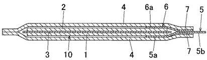
図1は、この発明の実施形態に係る電気化学デバイスが適用された薄形電池を封止状態で示す断面図、図2は、同じく薄形電池を封止前の状態で示す分解斜視図、図3は、同じく薄形電池を封止状態で示す分解断面図である。 1 is a sectional view showing a thin battery to which an electrochemical device according to an embodiment of the present invention is applied in a sealed state, and FIG. 2 is an exploded perspective view showing the thin battery in a state before sealing, FIG. 3 is an exploded cross-sectional view showing the thin battery in a sealed state.
図1〜図3において、この薄形電池は、正極1と負極2とがセパレータ3および/または固体電解質もしくはゲル電解質を介して積層されて電気化学素子10が構成される一方、正極1および負極2にそれぞれ各内端部5a,6aが電気的に接続された一対のリード端子5,6の各外端部5b,6bが外部に引き出されており、この状態で電気化学素子10が、例えば方形状に成形されている防湿性包装用ラミネート材料からなる外装フィルム4,4内に収容されている。
1 to 3, the thin battery includes a
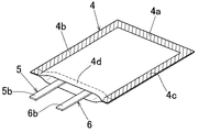
具体的には、図7に示すように、外装フィルム4,4の3辺(周辺)4a〜4cをヒートシールして袋状にして、その内部に電気化学素子10を収容してから、この外装フィルム4,4におけるシール部4dをヒートシールして密封したものである。勿論、外装フィルム4,4の形状等は、任意に変更可能である。
Specifically, as shown in FIG. 7, the three sides (peripheries) 4 a to 4 c of the
前記電気化学素子10における正極1および負極2は、金属箔、例えばアルミニウム箔ないしは銅箔等の表面にLiCoO2 やLiCoMn2 O4 等の正極材料およびLiC6 Ti5 O12等の負極材料が炭素導電助材やバインダとともに塗布された構成となっている。
The
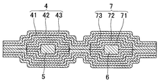
前記外装フィルム4は、積層状の構造、例えば図4に示すように3層構造であり、その最内層41は、熱接着性(熱可塑性)合成樹脂、例えば、高密度ポリエチレン、低密度ポリエチレン、直鎖状低密度ポリエチレン、ポリエチレン系のアイオノマー、ポリプロピレンのようなポリオレフィン樹脂等から選択されたもので構成されており、その最外層43は、ポリエチレンテレフタレート(PET)ないしはナイロンから選択されたもので構成されている。
The
外装フィルム4における中間層42は、金属箔、例えばアルミニウム箔ないしはSUS箔から選択されたもので構成されている。この中間層42により、外部からの水分の浸入や内部からの電解液の蒸発が有効に防止されている。また、最外層43は、機械的強度を確保し、中間層42を保護する役目をもっている。
The
この例における外装フィルム4は、最内層41として、融点が例えば168℃であるポリプロピレン未延伸フィルムを使用してドライラミネートした包装用ラミネート材料を袋状に加工したものが使用されている。
As the
前記正極側および負極側リード端子5,6は、アルミニウム、銅、ニッケル、ステンレス等の金属箔から構成されており、その厚みは、0.2〜0.5mmに設定されている。
The positive electrode side and negative electrode
つまり、このリード端子5,6には、大電流を流すために抵抗を下げる必要があり、その厚みは、0.2mm以上が好ましいが、最大でも0.5mm以下にするのがよい。厚みが0.5mmを超える場合、リード端子5,6の幅方向の両端縁に対して被覆フィルム7等の合成樹脂で埋めるのが困難となり、密着性の低下を招くおそれがあるからである。
That is, it is necessary to lower the resistance of the
前記外装フィルム4でヒートシールされる部位4dに対応して、両リード端子5,6には、厚みが、0.08〜0.25mmの3層構造の被覆フィルム7,7でそれぞれあらかじめ被覆されている。この被覆フィルム7により、リード端子5,6が外装フィルム4の中間層42に接触して短絡事故を起こすことを防止してある。
Corresponding to the
この被覆フィルム7における最内層71は、例えば図6に示すように、リード端子構成材である金属に対して密着性の良い接着性の合成樹脂で構成されており、その最内層71を覆う中間層72は、絶縁性樹脂で構成されている。また、外装フィルム4の最内層41に接触する最外層73は、該外装フィルム4の最内層41と同系統で相溶性の合成樹脂、例えばオレフィン樹脂で構成されている。
For example, as shown in FIG. 6, the
そして、この被覆フィルム7における最外層73の融点は、外装フィルム4の最内層41の融点未満に設定されており、この例では、融点差が9℃以上になるように、例えば外装フィルム4の最内層41の融点が168℃に対して、被覆フィルム7における最外層73の融点が、例えば134℃に設定されている。
The melting point of the
上記外装フィルム4,4に電気化学素子10を収容した後、外装フィルム4,4におけるシール部4dをヒートシールして密封するが、その場合、前記外装フィルム4,4における最内層41の融点(ここでは、168℃)よりも20℃以上の温度(188℃)でヒートシールを行う。
After the
このように、外装フィルム4におけるリード端子5,6に対応する部位をヒートシールするにあたって、前記リード端子5,6における被覆フィルム7の最外層73の融点を外装フィルム4の最内層41の融点未満に設定したから、前記ヒートシールを施した際、外装フィルム4の最内層41が溶融するに遅れることなくリード端子用被覆フィルム7の最外層73の溶融が開始され、前記シール部4dにおいて外装フィルム4の最内層41が溶融する時点になれば、金属製のリード端子5,6からの放熱が抑制された状態となっている。
Thus, when heat sealing the portions corresponding to the
従って、シール部4dにおいて被覆フィルム7における最外層73が外装フィルム4の最内層41に対して均一的に溶融し、両層41,73が良好に溶融し合って固結することになり、外装フィルム4のシール部4aにおける密封性が有効に強化される。
Accordingly, the
ところで、被覆フィルム7の最外層73の構成材と外装フィルム4の最内層41の構成材とは、熱接着性(熱可塑性)合成樹脂から任意に選択して設定可能であるが、この例のように、両層73,41を同系統の樹脂、例えばポリエチレン(PE)やポリプロピレン(PP)等のオレフィン系樹脂を採用してあると、両層73,41の相溶性が良好に発揮される。とくに、オレフィン系樹脂は耐薬品性に優れており、電解液との接触を考慮すると、積極的に使用できる。
By the way, the constituent material of the
また、被覆フィルム7の最外層73の融点と外装フィルム4の最内層41の融点との差は任意に設定可能であるが、この例のように融点差が9℃以上に設定することにより、外装フィルム4の最内層41の溶融と被覆フィルム7の最外層73との溶融が効果的に行われて、シール性能が一層高められる。
In addition, the difference between the melting point of the
また、リード端子5,6に対する被覆フィルム7の最外層73の融点が124℃未満の場合には、電池の耐熱性能への影響が懸念されるが、この例のように、被覆フィルム7の最外層73の融点を124℃以上に設定してあれば、耐熱性の低下のおそれも解消される。
Further, when the melting point of the
外装フィルム4の最内層41の融点が168℃を超える場合には、ヒートシールにエネルギーと時間がかかり、生産性が低下することから、168℃以下であることが好ましい。
When melting | fusing point of the
またヒートシール時間は、3〜8sec、望ましくは4〜6secに設定するのが良い。すなわちヒートシール時間が短過ぎる場合には、加熱不足により、確実にシールすることが困難になるおそれがある。逆に、ヒートシール時間が長過ぎる場合には、生産性が低下するとともに、加熱過多による熱劣化により、良好なシール状態を得ることが困難になるおそれがある。 The heat sealing time is set to 3 to 8 seconds, preferably 4 to 6 seconds. That is, when the heat seal time is too short, there is a risk that it is difficult to reliably seal due to insufficient heating. On the other hand, when the heat sealing time is too long, productivity is lowered, and it is difficult to obtain a good sealing state due to thermal deterioration due to excessive heating.
つぎに、上記構成の薄形電池による実施例および比較例について説明する。 Next, examples and comparative examples using the thin battery having the above-described configuration will be described.
なお、実施例と比較例は、包装用ラミネート材料からなる外装フィルム4の最外層43、中間層42の材質・厚み、リード端子5,6の厚みおよび幅は同じものとし、それぞれ次の通りである。
『外装フィルム4の最外層43と中間層42について』
ナイロン25μmからなる最外層43と、アルミニウム箔(AA規格8079、O材)からなる中間層42とをドライラミネートして使用する。
『リード端子について』
厚さ:0.2mm
幅:50mm
『ヒートシール条件について』
温度:外装フィルム4の最内層41の融点+30℃
圧力:0.2MPa
In the examples and comparative examples, the
“About the
The
About lead terminals
Thickness: 0.2mm
Width: 50mm
About heat seal conditions
Temperature: Melting point of
Pressure: 0.2MPa
〔実施例1〕
前記外装フィルム4における最内層41の構成材として、融点が168℃であるポリプロピレン未延伸フィルム30μmを選択し、これを最外層43となるナイロンと中間層42となるアルミニウム箔とにドライラミネートして包装用ラミネート材料を形成し、この包装用ラミネート材料を方形に成形するとともに、図7に示すように袋状に加工して外装フィルム4とした。
[Example 1]
As a constituent material of the
この外装フィルム4の内容物として(EC:DEC=1:1+1moILiPF6)の組成の疑似電解液10gを投入した後、最外層73が融点134℃のポリプロピレンからなる被覆フィルム7によりリード端子5,6におけるシール対応部位を被覆した。その後、前記外装フィルム4におけるシール部4dに対して5secのヒートシールを施して密封状態とした。
After 10 g of pseudo-electrolytic solution having a composition of (EC: DEC = 1: 1 + 1moILiPF6) is added as the contents of the
〔実施例2〕
前記外装フィルム4における最内層41の構成材として、融点が168℃であるポリプロピレン未延伸フィルム30μmを選択し、これを最外層43となるナイロンと中間層42となるアルミニウム箔とにドライラミネートして包装用ラミネート材料を形成し、この包装用ラミネート材料を方形に成形するとともに、袋状に加工して外装フィルム4とした。
[Example 2]
As a constituent material of the
この外装フィルム4の内容物として(EC:DEC=1:1+1moILiPF6)の組成の疑似電解液10gを投入した後、最外層73が融点143℃のポリプロピレンからなる被覆フィルム7によりリード端子5,6におけるシール対応部位を被覆した。その後、前記外装フィルム4におけるシール部4dに対して5secのヒートシールを施して密封状態とした。
After 10 g of pseudo-electrolytic solution having a composition of (EC: DEC = 1: 1 + 1moILiPF6) is added as the contents of the
〔実施例3〕
前記外装フィルム4における最内層41の構成材として、融点が143℃であるポリプロピレン未延伸フィルム30μmを選択し、これを最外層43となるナイロンと中間層42となるアルミニウム箔とにドライラミネートして包装用ラミネート材料を形成し、この包装用ラミネート材料を方形に成形するとともに、袋状に加工して外装フィルム4とした。
Example 3
As a constituent material of the
この外装フィルム4の内容物として(EC:DEC=1:1+1moILiPF6)の組成の疑似電解液10gを投入した後、最外層73が融点134℃のポリプロピレンからなる被覆フィルム7によりリード端子5,6におけるシール対応部位を被覆した。その後、前記外装フィルム4におけるシール部4dに対して5secのヒートシールを施して密封状態とした。
After 10 g of pseudo-electrolytic solution having a composition of (EC: DEC = 1: 1 + 1moILiPF6) is added as the contents of the
〔実施例4〕
前記外装フィルム4における最内層41の構成材として、融点が134℃であるポリプロピレン未延伸フィルム30μmを選択し、これを最外層43となるナイロンと中間層42となるアルミニウム箔とにドライラミネートして包装用ラミネート材料を形成し、この包装用ラミネート材料を方形に成形するとともに、袋状に加工して外装フィルム4とした。
Example 4
As a constituent material of the
この外装フィルム4の内容物として(EC:DEC=1:1+1moILiPF6)の組成の疑似電解液10gを投入した後、最外層73が融点124℃のポリプロピレンからなる被覆フィルム7によりリード端子5,6におけるシール対応部位を被覆した。その後前記外装フィルム4におけるシール部4dに対して5secのヒートシールを施して密封状態とした。
After 10 g of pseudo-electrolytic solution having a composition of (EC: DEC = 1: 1 + 1moILiPF6) is added as the contents of the
〔実施例5〕
前記外装フィルム4における最内層41の構成材として、融点が134℃であるポリプロピレン未延伸フィルム30μmを選択し、これを最外層43となるナイロンと中間層42となるアルミニウム箔とにドライラミネートして包装用ラミネート材料を形成し、この包装用ラミネート材料を方形に成形するとともに、袋状に加工して外装フィルム4とした。
Example 5
As a constituent material of the
この外装フィルム4の内容物として(EC:DEC=1:1+1moILiPF6)の組成の疑似電解液10gを投入した後、最外層73が融点126℃のポリプロピレンからなる被覆フィルム7によりリード端子5,6におけるシール対応部位を被覆した。その後、前記外装フィルム4におけるシール部4dに対して5secのヒートシールを施して密封状態とした。
After 10 g of pseudo-electrolytic solution having a composition of (EC: DEC = 1: 1 + 1moILiPF6) is added as the contents of the
〔比較例1〕
前記外装フィルム4における最内層41の構成材として、融点が168℃であるポリプロピレン未延伸フィルム30μmを選択し、これを最外層43となるナイロンと中間層42となるアルミニウム箔とにドライラミネートして包装用ラミネート材料を形成し、この包装用ラミネート材料を方形に成形するとともに、袋状に加工して外装フィルム4とした。
[Comparative Example 1]
As a constituent material of the
この外装フィルム4の内容物として(EC:DEC=1:1+1moILiPF6)の組成の疑似電解液10gを投入した後、最外層73が融点168℃のポリプロピレンからなる被覆フィルム7によりリード端子5,6におけるシール対応部位を被覆した。その後、前記外装フィルム4におけるシール部4dに対して5secのヒートシールを施して密封状態とした。
After putting 10 g of pseudoelectrolytic solution having the composition of (EC: DEC = 1: 1 + 1moILiPF6) as the contents of the
〔比較例2〕
前記外装フィルム4における最内層41の構成材として、融点が143℃であるポリプロピレン未延伸フィルム30μmを選択し、これを最外層43となるナイロンと中間層42となるアルミニウム箔とにドライラミネートして包装用ラミネート材料を形成し、この包装用ラミネート材料を方形に成形するとともに、袋状に加工して外装フィルム4とした。
[Comparative Example 2]
As a constituent material of the
この外装フィルム4の内容物として(EC:DEC=1:1+1moILiPF6)の組成の疑似電解液10gを投入した後、最外層73が融点143℃のポリプロピレンからなる被覆フィルム7によりリード端子5,6におけるシール対応部位を被覆した。その後、前記外装フィルム4におけるシール部4dに対して5secのヒートシールを施して密封状態とした。
After 10 g of pseudo-electrolytic solution having a composition of (EC: DEC = 1: 1 + 1moILiPF6) is added as the contents of the
〔比較例3〕
前記外装フィルム4における最内層41の構成材として、融点が134℃であるポリプロピレン未延伸フィルム30μmを選択し、これを最外層43となるナイロンと中間層42となるアルミニウム箔とにドライラミネートして包装用ラミネート材料を形成し、この包装用ラミネート材料を方形に成形するとともに、袋状に加工して外装フィルム4とした。
[Comparative Example 3]
As a constituent material of the
この外装フィルム4の内容物として(EC:DEC=1:1+1moILiPF6)の組成の疑似電解液10gを投入した後、最外層73が融点134℃のポリプロピレンからなる被覆フィルム7によりリード端子5,6におけるシール対応部位を被覆した。その後、前記外装フィルム4におけるシール部4dに対して5secのヒートシールを施して密封状態とした。
After 10 g of pseudo-electrolytic solution having a composition of (EC: DEC = 1: 1 + 1moILiPF6) is added as the contents of the
〔比較例4〕
比較例2と同条件であるが、ヒートシール時間を20secにて行った。
[Comparative Example 4]
The heat seal time was 20 sec under the same conditions as in Comparative Example 2.
〈密封性評価〉
各検体にタブ部が下向きになるよう静置して85℃で1週間の保存テストを行い、その後各検体内部に注射針より圧力を計測しながら空気を送り込み、破裂するに至る圧力を測定した。その結果を図8に示す。
<Sealability evaluation>
Each sample was left to stand with the tab portion facing downward, and a storage test was conducted at 85 ° C. for 1 week. Then, air was sent into each sample while measuring the pressure from the injection needle, and the pressure to rupture was measured. . The result is shown in FIG.
図8の表からも明らかなように、実施例においては、いずれも空気圧入装置の最大圧力である02MPaに至っても破裂することはなかったが、比較例においては、破裂し、密封性が劣ることが確認された。また、破裂の起点を確認したところ、外装フィルム4における最内層41と、リード端子5,6の被覆フィルム7における最外層73との界面であることが判った。
As is clear from the table of FIG. 8, in the examples, none of them burst even at the maximum pressure of 02 MPa, which is the maximum pressure of the pneumatic fitting device, but in the comparative example, it bursts and the sealing performance is inferior. It was confirmed. Further, when the starting point of the rupture was confirmed, it was found to be an interface between the
なお、この発明の実施形態においては、電気化学デバイスをとして、薄形電池に適用した例で説明したが、薄形電池に限らず、電気二重キャパシタ等の各種電気化学デバイスに適用可能である。 In the embodiment of the present invention, the electrochemical device is described as an example applied to a thin battery. However, the present invention is not limited to a thin battery, and can be applied to various electrochemical devices such as an electric double capacitor. .
この発明の電気化学デバイスは、電気自動車や携帯電話等の電源として利用可能である。 The electrochemical device of the present invention can be used as a power source for electric vehicles, mobile phones and the like.
1・・・正極
2・・・負極
3・・・電解質
4・・・外装フィルム
4d・・・外装フィルムのシール部
5・・・正極側リード端子
5a・・・正極側リード端子の内端部
5b・・・正極側リード端子の外端部
6・・・負極側リード端子
6a・・・負極側リード端子の内端部
6b・・・負極側リード端子の外端部
7・・・・リード端子用被覆フィルム
10・・・電気化学素子
41・・・外装フィルムの最内層
73・・・リード端子用被覆フィルムの最外層
DESCRIPTION OF
Claims (8)
前記外装フィルムに収容された電気化学素子と、
内端部が前記電気化学素子に電気的に接続されて、外端部が外装フィルムから外部に引き出されたリード端子と、
最外層が前記外装フィルムの最内層と相溶性を有する熱接着性合成樹脂で構成されて、前記外装フィルムによるシール部に対応して設けられた積層状のリード端子用被覆フィルムとを備えており、
前記リード端子を前記被覆フィルムを介して挟んだ状態で前記外装フィルムによるシール部がヒートシールで融着され、
前記リード端子用被覆フィルムにおける最外層の融点が前記外装フィルムの最内層の融点未満に設定され、
前記外装フィルムにおける最内層の融点と前記リード端子用被覆フィルムにおける最外層の融点との差が9℃以上であり、
前記外装フィルムにおける最内層の融点が124℃以上であり、
リード端子用被覆フィルムにおける最外層の融点が168℃以下であり、
前記外装フィルムにおける最内層と前記リード端子用被覆フィルムにおける最外層とが同系統の合成樹脂で構成されていることを特徴とする電気化学デバイス。 A laminated exterior film having at least an innermost layer made of a heat-adhesive synthetic resin; and
An electrochemical element housed in the exterior film;
A lead terminal whose inner end is electrically connected to the electrochemical element and whose outer end is drawn out of the exterior film;
The outermost layer is composed of a heat-adhesive synthetic resin that is compatible with the innermost layer of the exterior film, and includes a laminated lead terminal covering film provided corresponding to the seal portion by the exterior film. ,
In a state where the lead terminal is sandwiched through the covering film, the seal portion by the exterior film is fused by heat sealing,
The melting point of the outermost layer in the coating film for lead terminals is set to be less than the melting point of the innermost layer of the exterior film ,
The difference between the melting point of the innermost layer in the exterior film and the melting point of the outermost layer in the lead terminal covering film is 9 ° C. or more,
The melting point of the innermost layer in the exterior film is 124 ° C. or higher,
The melting point of the outermost layer in the lead terminal covering film is 168 ° C. or lower,
An electrochemical device , wherein an innermost layer in the outer film and an outermost layer in the lead terminal covering film are made of the same type of synthetic resin .
前記リード端子の一部を前記被覆フィルムにて被覆する工程と、
前記外装フィルムに、電気化学素子を収容する工程と、
リード端子をその外端部を前記外装フィルムから引き出した状態で内端部を前記電気化学素子に電気的に接続する工程と、
前記リード端子を部分的に被覆した前記被覆フィルムに、前記外装フィルムによるシール部をヒートシールにて融着する工程と、を含むことを特徴とする電気化学デバイスの製造方法。 At least the innermost layer is made of a thermoadhesive synthetic resin having a laminated outer film made of a thermoadhesive synthetic resin, an electrochemical element, a lead terminal, and an outermost layer having compatibility with the innermost layer of the outer film, and its melting point of the outermost layer is set to the innermost layer below the melting point of the outer film Rutotomoni, the laminate-shaped lead terminals difference between the innermost layer of the melting point of 9 ° C. or higher at the melting point and the outer film of the outermost layer A step of preparing a coating film;
Coating a part of the lead terminal with the coating film;
Storing the electrochemical element in the exterior film;
Electrically connecting the inner end to the electrochemical element in a state where the outer end of the lead terminal is pulled out from the exterior film; and
A method of manufacturing an electrochemical device, comprising: fusing a seal portion of the exterior film to the covering film partially covering the lead terminal by heat sealing.
Priority Applications (7)
| Application Number | Priority Date | Filing Date | Title |
|---|---|---|---|
| JP2009004913A JP5457040B2 (en) | 2009-01-13 | 2009-01-13 | Electrochemical device and manufacturing method thereof |
| US13/144,127 US20120082888A1 (en) | 2009-01-13 | 2010-01-08 | Electrochemical device and process of manufacturing same |
| EP10731201.9A EP2383818A4 (en) | 2009-01-13 | 2010-01-08 | Electrochemical device and process of manufacturing same |
| SG2011051612A SG173025A1 (en) | 2009-01-13 | 2010-01-08 | Electrochemical device and process of manufacturing same |
| PCT/JP2010/050129 WO2010082532A1 (en) | 2009-01-13 | 2010-01-08 | Electrochemical device and process of manufacturing same |
| CN2010800111184A CN102349174A (en) | 2009-01-13 | 2010-01-08 | Electrochemical device and process of manufacturing same |
| KR1020117016160A KR101280798B1 (en) | 2009-01-13 | 2010-01-08 | Electrochemical device and process of manufacturing same |
Applications Claiming Priority (1)
| Application Number | Priority Date | Filing Date | Title |
|---|---|---|---|
| JP2009004913A JP5457040B2 (en) | 2009-01-13 | 2009-01-13 | Electrochemical device and manufacturing method thereof |
Publications (2)
| Publication Number | Publication Date |
|---|---|
| JP2010165481A JP2010165481A (en) | 2010-07-29 |
| JP5457040B2 true JP5457040B2 (en) | 2014-04-02 |
Family
ID=42339785
Family Applications (1)
| Application Number | Title | Priority Date | Filing Date |
|---|---|---|---|
| JP2009004913A Active JP5457040B2 (en) | 2009-01-13 | 2009-01-13 | Electrochemical device and manufacturing method thereof |
Country Status (7)
| Country | Link |
|---|---|
| US (1) | US20120082888A1 (en) |
| EP (1) | EP2383818A4 (en) |
| JP (1) | JP5457040B2 (en) |
| KR (1) | KR101280798B1 (en) |
| CN (1) | CN102349174A (en) |
| SG (1) | SG173025A1 (en) |
| WO (1) | WO2010082532A1 (en) |
Families Citing this family (16)
| Publication number | Priority date | Publication date | Assignee | Title |
|---|---|---|---|---|
| JP5374742B2 (en) * | 2010-10-27 | 2013-12-25 | 日新製鋼株式会社 | Laminate battery exterior material, laminate battery exterior material manufacturing method, and laminate battery manufacturing method |
| KR20120126932A (en) * | 2011-05-13 | 2012-11-21 | 에스케이이노베이션 주식회사 | Sealing method and device of pouch type secondary battery |
| JP2013134818A (en) | 2011-12-26 | 2013-07-08 | Showa Denko Kk | Terminal lead |
| CN104145350B (en) * | 2012-02-29 | 2017-07-21 | 日新制钢株式会社 | The manufacture method of the outer casing member of Stackable batteries, the manufacture method of the outer casing member of Stackable batteries and Stackable batteries |
| KR102275359B1 (en) | 2013-06-14 | 2021-07-09 | 도판 인사츠 가부시키가이샤 | Resin film, metal terminal member, and secondary cell |
| JP6094808B2 (en) * | 2013-07-03 | 2017-03-15 | 株式会社デンソー | Laminated sealed battery |
| TWI656680B (en) * | 2013-07-17 | 2019-04-11 | 日商凸版印刷股份有限公司 | Resin film covering secondary battery terminals and manufacturing method thereof, tab member for secondary battery, and secondary battery |
| KR101400845B1 (en) | 2013-10-15 | 2014-05-29 | 금정산업 주식회사 | High-temperature vacuum compression bag for multilayer ceramic capacitors manufacturing |
| KR101851485B1 (en) | 2014-03-19 | 2018-04-23 | 도판 인사츠 가부시키가이샤 | Secondary battery |
| JP6426934B2 (en) * | 2014-07-29 | 2018-11-21 | 昭和電工パッケージング株式会社 | Electrochemical device and method of manufacturing the same |
| US9634301B2 (en) | 2015-01-05 | 2017-04-25 | Johnson Controls Technology Company | Lithium ion battery cell with secondary seal |
| USD773390S1 (en) | 2015-02-27 | 2016-12-06 | Johnson Controls Technology Company | Lithium ion battery cell |
| US20160351865A1 (en) * | 2015-05-27 | 2016-12-01 | GM Global Technology Operations LLC | Folded laminate battery cell |
| CN106977894A (en) * | 2017-04-20 | 2017-07-25 | 中航锂电(洛阳)有限公司 | A kind of composite flame-proof plastic material, composite flame-proof working of plastics, the battery case and lithium ion battery of vest structure |
| JP7120501B1 (en) * | 2021-12-27 | 2022-08-17 | 住友電気工業株式会社 | Lead wire for non-aqueous electrolyte battery, insulating film and non-aqueous electrolyte battery |
| CN116670899A (en) * | 2021-12-27 | 2023-08-29 | 住友电气工业株式会社 | Lead wire for nonaqueous electrolyte battery, insulating film, and nonaqueous electrolyte battery |
Family Cites Families (21)
| Publication number | Priority date | Publication date | Assignee | Title |
|---|---|---|---|---|
| JPS5938708B2 (en) | 1979-03-26 | 1984-09-18 | 松下電器産業株式会社 | flat battery |
| JPS5938708A (en) | 1982-08-30 | 1984-03-02 | Fujitsu Ltd | Optical fiber connector |
| JPS6086754A (en) * | 1983-10-19 | 1985-05-16 | Hitachi Ltd | Sheet battery |
| JPH06196170A (en) * | 1992-06-30 | 1994-07-15 | Japan Storage Battery Co Ltd | Nonaqueous electrolyte secondary battery |
| JPH0722021A (en) * | 1993-06-28 | 1995-01-24 | Sumitomo Electric Ind Ltd | Carbon electrode for lithium secondary battery and manufacture thereof |
| JP3767151B2 (en) | 1997-02-26 | 2006-04-19 | ソニー株式会社 | Thin battery |
| JP4491843B2 (en) * | 1998-02-24 | 2010-06-30 | ソニー株式会社 | Lithium ion secondary battery and method of sealing a lithium ion secondary battery container |
| JP4622019B2 (en) * | 1999-01-20 | 2011-02-02 | パナソニック株式会社 | Flat battery |
| JP2000268789A (en) * | 1999-03-19 | 2000-09-29 | Hitachi Maxell Ltd | Sealant for thin battery |
| JP2000285885A (en) * | 1999-03-30 | 2000-10-13 | Japan Storage Battery Co Ltd | Manufacture of battery |
| JP4138172B2 (en) | 1999-08-20 | 2008-08-20 | Tdk株式会社 | Electrochemical device and manufacturing method thereof |
| CN1288769C (en) * | 2001-01-18 | 2006-12-06 | 大日本印刷株式会社 | Battery device and lead wire film |
| JP2004319099A (en) * | 2003-04-11 | 2004-11-11 | Sii Micro Parts Ltd | Electrochemical cell |
| JP4595302B2 (en) * | 2003-09-04 | 2010-12-08 | 日産自動車株式会社 | Bipolar battery |
| US7749652B2 (en) * | 2004-09-30 | 2010-07-06 | Sumitomo Electric Industries, Ltd. | Lead and nonaqueous electrolyte battery including same |
| JP4784236B2 (en) * | 2004-09-30 | 2011-10-05 | 住友電気工業株式会社 | Non-aqueous electrolyte battery lead wire and non-aqueous electrolyte battery |
| JP2007087801A (en) * | 2005-09-22 | 2007-04-05 | Sharp Corp | Lithium ion secondary battery |
| JP5169820B2 (en) * | 2006-03-13 | 2013-03-27 | 日本電気株式会社 | Film exterior electrical device |
| JP4508199B2 (en) * | 2007-02-05 | 2010-07-21 | ソニー株式会社 | Lead sealant film and non-aqueous electrolyte battery |
| JP4895928B2 (en) | 2007-06-19 | 2012-03-14 | 株式会社リコー | Image processing apparatus, application execution method, and application execution program |
| JP5308696B2 (en) * | 2008-03-17 | 2013-10-09 | 藤森工業株式会社 | Sealing film and electrode with sealing film |
-
2009
- 2009-01-13 JP JP2009004913A patent/JP5457040B2/en active Active
-
2010
- 2010-01-08 US US13/144,127 patent/US20120082888A1/en not_active Abandoned
- 2010-01-08 EP EP10731201.9A patent/EP2383818A4/en not_active Withdrawn
- 2010-01-08 WO PCT/JP2010/050129 patent/WO2010082532A1/en active Application Filing
- 2010-01-08 KR KR1020117016160A patent/KR101280798B1/en active IP Right Grant
- 2010-01-08 CN CN2010800111184A patent/CN102349174A/en active Pending
- 2010-01-08 SG SG2011051612A patent/SG173025A1/en unknown
Also Published As
| Publication number | Publication date |
|---|---|
| SG173025A1 (en) | 2011-08-29 |
| EP2383818A1 (en) | 2011-11-02 |
| CN102349174A (en) | 2012-02-08 |
| US20120082888A1 (en) | 2012-04-05 |
| KR20110105799A (en) | 2011-09-27 |
| WO2010082532A1 (en) | 2010-07-22 |
| KR101280798B1 (en) | 2013-07-05 |
| EP2383818A4 (en) | 2015-03-11 |
| JP2010165481A (en) | 2010-07-29 |
Similar Documents
| Publication | Publication Date | Title |
|---|---|---|
| JP5457040B2 (en) | Electrochemical device and manufacturing method thereof | |
| JP5422842B2 (en) | Electrochemical devices | |
| US9450215B2 (en) | Outer casing material for battery and lithium secondary battery | |
| JP5171824B2 (en) | Electricity storage device | |
| JP4828458B2 (en) | Secondary battery with improved sealing safety | |
| JP2014026980A (en) | Electrochemical device | |
| KR101213352B1 (en) | Lead member, battery deivce having the lead member and method for manufacturing the lead member | |
| KR101229228B1 (en) | Secondary Battery with Improved Moisture Barrier | |
| JP6121710B2 (en) | Battery exterior material and lithium secondary battery | |
| JP2006252802A (en) | Tab lead for nonaqueous electrolyte battery and nonaqueous electrolyte battery | |
| JP2018037398A (en) | Electrochemical cell and method for manufacturing electrochemical cell | |
| KR20150051178A (en) | Pouch-type secondary battery for preventing humidity penetration | |
| JP2007005101A (en) | Nonaqueous electrolyte battery and lead wire for nonaqueous electrolyte battery | |
| JP2010033888A (en) | Lead wire for nonaqueous electrolyte battery and nonaqueous electrolyte battery | |
| KR101546002B1 (en) | electrochemical energy storage device | |
| JP2013239398A (en) | Lead terminal for power storage device, and nonaqueous electrolyte power storage device equipped with the same | |
| JP4375148B2 (en) | Nonaqueous electrolyte battery and lead wire for nonaqueous electrolyte battery | |
| JP2016197491A (en) | Jacket material for battery and battery using the same | |
| CN114597600B (en) | Laminated battery | |
| JP2015156404A (en) | Exterior material for battery and lithium secondary battery | |
| JP2023014551A (en) | Tab lead, method of manufacturing the same, and laminate type battery or capacitor including the tab lead | |
| JP2007005102A (en) | Nonaqueous electrolyte battery and lead wire for nonaqueous electrolyte battery | |
| JP2023014550A (en) | Tab lead, method of manufacturing the same, and laminate type battery or capacitor including the tab lead | |
| JP2015103291A (en) | Laminate battery | |
| JP2002157980A (en) | Sealing bag for nonaqueous electrolyte battery and nonaqueous electrolyte battery using this bag |
Legal Events
| Date | Code | Title | Description |
|---|---|---|---|
| A621 | Written request for application examination |
Free format text: JAPANESE INTERMEDIATE CODE: A621 Effective date: 20111111 |
|
| A131 | Notification of reasons for refusal |
Free format text: JAPANESE INTERMEDIATE CODE: A131 Effective date: 20130903 |
|
| A521 | Request for written amendment filed |
Free format text: JAPANESE INTERMEDIATE CODE: A523 Effective date: 20131023 |
|
| A711 | Notification of change in applicant |
Free format text: JAPANESE INTERMEDIATE CODE: A711 Effective date: 20131030 |
|
| TRDD | Decision of grant or rejection written | ||
| A521 | Request for written amendment filed |
Free format text: JAPANESE INTERMEDIATE CODE: A821 Effective date: 20131030 |
|
| A01 | Written decision to grant a patent or to grant a registration (utility model) |
Free format text: JAPANESE INTERMEDIATE CODE: A01 Effective date: 20131217 |
|
| A61 | First payment of annual fees (during grant procedure) |
Free format text: JAPANESE INTERMEDIATE CODE: A61 Effective date: 20140109 |
|
| R150 | Certificate of patent or registration of utility model |
Ref document number: 5457040 Country of ref document: JP Free format text: JAPANESE INTERMEDIATE CODE: R150 Free format text: JAPANESE INTERMEDIATE CODE: R150 |
|
| RD02 | Notification of acceptance of power of attorney |
Free format text: JAPANESE INTERMEDIATE CODE: R3D02 |
|
| R250 | Receipt of annual fees |
Free format text: JAPANESE INTERMEDIATE CODE: R250 |
|
| R250 | Receipt of annual fees |
Free format text: JAPANESE INTERMEDIATE CODE: R250 |
|
| R250 | Receipt of annual fees |
Free format text: JAPANESE INTERMEDIATE CODE: R250 |
|
| R250 | Receipt of annual fees |
Free format text: JAPANESE INTERMEDIATE CODE: R250 |
|
| R250 | Receipt of annual fees |
Free format text: JAPANESE INTERMEDIATE CODE: R250 |
|
| S531 | Written request for registration of change of domicile |
Free format text: JAPANESE INTERMEDIATE CODE: R313531 |
|
| S533 | Written request for registration of change of name |
Free format text: JAPANESE INTERMEDIATE CODE: R313533 |
|
| R350 | Written notification of registration of transfer |
Free format text: JAPANESE INTERMEDIATE CODE: R350 |
|
| R250 | Receipt of annual fees |
Free format text: JAPANESE INTERMEDIATE CODE: R250 |