JP4677251B2 - Flow cell, flow cell manufacturing method, and fluid concentration measuring apparatus - Google Patents
Flow cell, flow cell manufacturing method, and fluid concentration measuring apparatus Download PDFInfo
- Publication number
- JP4677251B2 JP4677251B2 JP2005051280A JP2005051280A JP4677251B2 JP 4677251 B2 JP4677251 B2 JP 4677251B2 JP 2005051280 A JP2005051280 A JP 2005051280A JP 2005051280 A JP2005051280 A JP 2005051280A JP 4677251 B2 JP4677251 B2 JP 4677251B2
- Authority
- JP
- Japan
- Prior art keywords
- tube
- light
- light projecting
- flow cell
- receiving member
- Prior art date
- Legal status (The legal status is an assumption and is not a legal conclusion. Google has not performed a legal analysis and makes no representation as to the accuracy of the status listed.)
- Active
Links
- 239000012530 fluid Substances 0.000 title claims description 105
- 238000004519 manufacturing process Methods 0.000 title claims description 16
- 238000005259 measurement Methods 0.000 claims description 70
- 239000000463 material Substances 0.000 claims description 27
- 238000003825 pressing Methods 0.000 claims description 13
- 230000001105 regulatory effect Effects 0.000 claims description 10
- 239000004033 plastic Substances 0.000 claims description 9
- 230000015572 biosynthetic process Effects 0.000 claims description 8
- 230000000704 physical effect Effects 0.000 claims description 5
- 229920005989 resin Polymers 0.000 claims description 3
- 239000011347 resin Substances 0.000 claims description 3
- NBVXSUQYWXRMNV-UHFFFAOYSA-N fluoromethane Chemical compound FC NBVXSUQYWXRMNV-UHFFFAOYSA-N 0.000 claims 1
- 238000000034 method Methods 0.000 description 29
- 239000011162 core material Substances 0.000 description 15
- KRHYYFGTRYWZRS-UHFFFAOYSA-N Fluorane Chemical compound F KRHYYFGTRYWZRS-UHFFFAOYSA-N 0.000 description 12
- 230000003287 optical effect Effects 0.000 description 12
- 238000012545 processing Methods 0.000 description 10
- 239000007788 liquid Substances 0.000 description 9
- 239000002253 acid Substances 0.000 description 8
- 239000003795 chemical substances by application Substances 0.000 description 7
- 238000004140 cleaning Methods 0.000 description 7
- 239000010453 quartz Substances 0.000 description 7
- VYPSYNLAJGMNEJ-UHFFFAOYSA-N silicon dioxide Inorganic materials O=[Si]=O VYPSYNLAJGMNEJ-UHFFFAOYSA-N 0.000 description 7
- QTBSBXVTEAMEQO-UHFFFAOYSA-N Acetic acid Chemical compound CC(O)=O QTBSBXVTEAMEQO-UHFFFAOYSA-N 0.000 description 6
- XUIMIQQOPSSXEZ-UHFFFAOYSA-N Silicon Chemical compound [Si] XUIMIQQOPSSXEZ-UHFFFAOYSA-N 0.000 description 6
- 229910052594 sapphire Inorganic materials 0.000 description 6
- 239000010980 sapphire Substances 0.000 description 6
- 239000004065 semiconductor Substances 0.000 description 6
- 229910052710 silicon Inorganic materials 0.000 description 6
- 239000010703 silicon Substances 0.000 description 6
- 239000000126 substance Substances 0.000 description 6
- 230000004927 fusion Effects 0.000 description 5
- 239000004973 liquid crystal related substance Substances 0.000 description 5
- -1 perfluoro Chemical group 0.000 description 5
- 239000004812 Fluorinated ethylene propylene Substances 0.000 description 4
- VEXZGXHMUGYJMC-UHFFFAOYSA-N Hydrochloric acid Chemical compound Cl VEXZGXHMUGYJMC-UHFFFAOYSA-N 0.000 description 4
- NBIIXXVUZAFLBC-UHFFFAOYSA-N Phosphoric acid Chemical compound OP(O)(O)=O NBIIXXVUZAFLBC-UHFFFAOYSA-N 0.000 description 4
- QAOWNCQODCNURD-UHFFFAOYSA-N Sulfuric acid Chemical compound OS(O)(=O)=O QAOWNCQODCNURD-UHFFFAOYSA-N 0.000 description 4
- 229920009441 perflouroethylene propylene Polymers 0.000 description 4
- 229920001343 polytetrafluoroethylene Polymers 0.000 description 4
- 239000004810 polytetrafluoroethylene Substances 0.000 description 4
- 230000002411 adverse Effects 0.000 description 3
- 229910052782 aluminium Inorganic materials 0.000 description 3
- XAGFODPZIPBFFR-UHFFFAOYSA-N aluminium Chemical compound [Al] XAGFODPZIPBFFR-UHFFFAOYSA-N 0.000 description 3
- 230000005540 biological transmission Effects 0.000 description 3
- WUKWITHWXAAZEY-UHFFFAOYSA-L calcium difluoride Chemical compound [F-].[F-].[Ca+2] WUKWITHWXAAZEY-UHFFFAOYSA-L 0.000 description 3
- 229910001634 calcium fluoride Inorganic materials 0.000 description 3
- 238000001514 detection method Methods 0.000 description 3
- 230000001678 irradiating effect Effects 0.000 description 3
- ZOXJGFHDIHLPTG-UHFFFAOYSA-N Boron Chemical compound [B] ZOXJGFHDIHLPTG-UHFFFAOYSA-N 0.000 description 2
- GRYLNZFGIOXLOG-UHFFFAOYSA-N Nitric acid Chemical compound O[N+]([O-])=O GRYLNZFGIOXLOG-UHFFFAOYSA-N 0.000 description 2
- 239000000853 adhesive Substances 0.000 description 2
- 230000001070 adhesive effect Effects 0.000 description 2
- 229910000147 aluminium phosphate Inorganic materials 0.000 description 2
- 229910052796 boron Inorganic materials 0.000 description 2
- HQQADJVZYDDRJT-UHFFFAOYSA-N ethene;prop-1-ene Chemical group C=C.CC=C HQQADJVZYDDRJT-UHFFFAOYSA-N 0.000 description 2
- 239000011521 glass Substances 0.000 description 2
- 239000007769 metal material Substances 0.000 description 2
- 229910017604 nitric acid Inorganic materials 0.000 description 2
- 238000001259 photo etching Methods 0.000 description 2
- 229910001220 stainless steel Inorganic materials 0.000 description 2
- 239000010935 stainless steel Substances 0.000 description 2
- 238000003756 stirring Methods 0.000 description 2
- 229920001651 Cyanoacrylate Polymers 0.000 description 1
- 239000004593 Epoxy Substances 0.000 description 1
- MWCLLHOVUTZFKS-UHFFFAOYSA-N Methyl cyanoacrylate Chemical compound COC(=O)C(=C)C#N MWCLLHOVUTZFKS-UHFFFAOYSA-N 0.000 description 1
- 150000007513 acids Chemical class 0.000 description 1
- 238000007664 blowing Methods 0.000 description 1
- 238000007796 conventional method Methods 0.000 description 1
- 238000010586 diagram Methods 0.000 description 1
- 229910052736 halogen Inorganic materials 0.000 description 1
- 150000002367 halogens Chemical class 0.000 description 1
- 238000002844 melting Methods 0.000 description 1
- 230000008018 melting Effects 0.000 description 1
- 239000002184 metal Substances 0.000 description 1
- 229910052751 metal Inorganic materials 0.000 description 1
- 150000002739 metals Chemical class 0.000 description 1
- 238000002156 mixing Methods 0.000 description 1
- 239000000203 mixture Substances 0.000 description 1
- 239000005304 optical glass Substances 0.000 description 1
- 238000012546 transfer Methods 0.000 description 1
- 238000002834 transmittance Methods 0.000 description 1
- WFKWXMTUELFFGS-UHFFFAOYSA-N tungsten Chemical compound [W] WFKWXMTUELFFGS-UHFFFAOYSA-N 0.000 description 1
- 229910052721 tungsten Inorganic materials 0.000 description 1
- 239000010937 tungsten Substances 0.000 description 1
- XLYOFNOQVPJJNP-UHFFFAOYSA-N water Substances O XLYOFNOQVPJJNP-UHFFFAOYSA-N 0.000 description 1
Images


Description
本発明は、例えば半導体や液晶表示装置等の製造工程に使用される流体における被測定物の測定用として配管に取り付けられるフローセル、該フローセルの製造方法、及び上記フローセルを備えた流体濃度測定装置に関する。 The present invention relates to, for example, a flow cell attached to a pipe for measuring an object to be measured in a fluid used in a manufacturing process of a semiconductor or a liquid crystal display device, a method for manufacturing the flow cell, and a fluid concentration measuring apparatus including the flow cell. .
一般に、半導体や液晶表示装置等の製造工程において、使用する流体つまりプロセス用薬剤水溶液に含まれる薬剤の濃度を正確、簡単かつ迅速に測定することは、これら製造分野において広く要請されている課題である。 In general, in the manufacturing process of semiconductors, liquid crystal display devices, etc., it is a widely requested issue in these manufacturing fields to accurately, easily and quickly measure the concentration of the chemical contained in the fluid used, that is, the aqueous chemical solution for processing. is there.
半導体の分野におけるシリコンウエハ洗浄工程やフォトエッチング工程あるいは液晶表示装置の製造工程等で使用されている酸、例えばフッ酸、硝酸、酢酸、リン酸、塩酸、硫酸等の混合物等の処理液に関しては、製品の歩留の向上、安全性や作業効率等の観点から、これら処理液中の酸の濃度管理が不可欠であり、そのための濃度分析とこの濃度分析に基づいて所定の濃度となるように酸を自動的に供給する自動化が要請されている。 Regarding processing solutions such as acids, such as hydrofluoric acid, nitric acid, acetic acid, phosphoric acid, hydrochloric acid, and sulfuric acid, which are used in silicon wafer cleaning processes, photoetching processes, and liquid crystal display manufacturing processes in the semiconductor field From the standpoints of improving product yield, safety, and work efficiency, it is essential to control the concentration of acid in these processing solutions, and to achieve a predetermined concentration based on this concentration analysis and concentration analysis. There is a demand for automation to automatically supply acid.
上記処理液のような流体に含まれる被測定物の濃度を測定する方法の一つとして、配管を流れる流体に光を照射しその透過光強度を測定する方法がある(例えば、特許文献1参照。)。上記透過光強度を測定するためにフローセルが配管に設けられる。ここでフローセルとは、試料液体へ光線を照射するために用いる光透過性材料にて形成された流路部分である。
フローセルは、流体の流れ方向に直交し光が流体を透過するように設けられる光の通路を備えるが、該光通路長の変動を低減することが流体を透過する透過光の強度を高精度に測定するための要件の一つである。通常、上記光通路長は、配管の内径よりも小さく、従来のフローセルでは、配管を偏平な形に絞り込む、あるいは小径の管を途中に介在させる等の構成を採ることで、必要な光通路長を得ている。しかしながら、このようなフローセルでは、配管を流れる流体にとってフローセルが抵抗となることから、流体の圧力損失を大きくしてしまうという問題がある。
As one of methods for measuring the concentration of an object to be measured contained in a fluid such as the treatment liquid, there is a method of irradiating a fluid flowing through a pipe with light and measuring the transmitted light intensity (see, for example, Patent Document 1). .) In order to measure the transmitted light intensity, a flow cell is provided in the pipe. Here, the flow cell is a channel portion formed of a light transmissive material used for irradiating a sample liquid with light.
The flow cell is provided with a light path provided so that light passes through the fluid perpendicular to the fluid flow direction, and reducing the fluctuation of the light path length increases the intensity of transmitted light that passes through the fluid with high accuracy. It is one of the requirements for measuring. Usually, the optical path length is smaller than the inner diameter of the pipe, and in the conventional flow cell, the required optical path length can be obtained by narrowing the pipe to a flat shape or interposing a small diameter pipe in the middle. Have gained. However, in such a flow cell, there is a problem in that the pressure loss of the fluid is increased because the flow cell becomes a resistance to the fluid flowing through the pipe.
このような圧力損失の問題を解決すべく、光透過部の周囲に、管の流路断面積にほぼ等しい断面積を有する流体通路を設けたフローセルも提案されている(例えば特許文献2参照)。上述のように、測定精度において光通路長が重要な要件の一つであるが、配管内の流体の温度等の影響により光通路長は変化し易い。よって、上記特許文献2に開示されるフローセルにおいも、光透過部は石英のような熱膨張率の低い材料にて形成し、光通路長が変動しないようにしている。
しかしながら、上記特許文献2に開示されるフローセルであっても、図11に示すように、フローセルの光透過部12は管内に配置されており、圧力損失の問題を低減したとしても、管内、つまり流体に接触する形態にて異物を配置するという問題が存在する。即ち、流体が例えば上述のようなシリコンウエハ洗浄工程等に使用される処理液であるとき、洗浄工程では有機物や金属等の混入は絶対に避けねばならず、測定用とは言え配管内に処理液以外の異物が存在することは好ましくない。又、上述したフッ酸等の酸に耐え得る材料としては、フッ素樹脂、石英、サファイヤがあるが、例えば石英は、フッ酸に浸食されることから、上述のような石英を使った光透過部12を有するフローセルは使用できない。又、サファイヤではアルミが溶出することから、測定された流体は廃棄しなければならない。このように、配管内に光透過部を設ける構成では、適用流体が限定されたり、流体を循環して使用できない等の問題を生じる。
さらに又、配管形状とは異なる形状を有するフローセルを設けた場合には、配管から流体を排出した後においてもフローセル部分に液溜まりが生じたり、上述のように圧力損失の発生や、流速の変化等も発生し、フローセルを設けたシステム全体へ悪影響を招くことも懸念される。
However, even in the flow cell disclosed in the above-mentioned Patent Document 2, as shown in FIG. 11, the
In addition, when a flow cell having a shape different from the piping shape is provided, even after the fluid is discharged from the piping, a liquid pool is generated in the flow cell portion. Etc. may occur, and there is a concern that the entire system provided with the flow cell may be adversely affected.
さらに又、上述したような問題点を解決するため、予め投光部及び受光部を設置した部分に配管をセットするように構成することで、配管自体には何ら細工を施さずに測定を可能とした測定器も存在する。しかしながら、このような構成では、管壁と、投光部及び受光部とが密着しないことから、投光部から配管に照射される光、並びに、配管及び流体を通過して受光部に入射する光の強度自体が変動してしまうことが懸念される。又、上述したように、配管内の流体の温度や圧力等の作用により、配管自体が伸縮することから、上述の、管壁と、投光部及び受光部との密着不良に起因して、上記光通路長が変動することも懸念される。したがって、このような測定器では、満足な測定値精度が得られないと考えられる。 Furthermore, in order to solve the above-mentioned problems, it is possible to perform measurement without any work on the piping itself by configuring the piping to be set in the part where the light projecting unit and the light receiving unit are installed in advance. There is also a measuring instrument. However, in such a configuration, the tube wall, the light projecting unit, and the light receiving unit are not in close contact with each other. Therefore, the light irradiated from the light projecting unit to the pipe and the pipe and the fluid are incident on the light receiving unit. There is a concern that the intensity of light itself may fluctuate. Also, as described above, because the pipe itself expands and contracts due to the action of the temperature and pressure of the fluid in the pipe, due to the poor adhesion between the pipe wall, the light projecting part and the light receiving part, There is also a concern that the optical path length fluctuates. Therefore, it is considered that such a measuring device cannot obtain satisfactory measurement value accuracy.
本発明は、上述したような問題点を解決するためになされたもので、従来に比べて高精度にて流体内の被測定物の測定が行える、フローセル、フローセルの製造方法、及び流体濃度測定装置を提供することを目的とする。 The present invention has been made to solve the above-described problems. A flow cell, a flow cell manufacturing method, and a fluid concentration measurement capable of measuring an object to be measured in a fluid with higher accuracy than conventional methods. An object is to provide an apparatus.
上記目的を達成するため、本発明は以下のように構成する。
即ち、本発明の第1態様におけるフローセルは、可塑性で透光性の材料からなり被測定物の流体が流れる管と、
上記管に交差する方向から上記管を挟み、かつ上記管に密着して上記管と一体的に形成され、上記流体の物性測定用の測定光を通過させる一対の投受光用部材と、
上記投受光用部材に取り付けられ、上記一対の投受光用部材間の部材間距離を上記管の変形に関係なく常に一定に保持する保持部材と、
を備え、
上記投受光用部材は上記管に融着して固定される、
ことを特徴とする。
また、本発明の他の態様におけるフローセルは、可塑性で透光性の材料からなり被測定物の流体が流れる管と、
上記管に交差する方向から上記管を挟み、かつ上記管に密着して上記管と一体的に形成され、上記流体の物性測定用の測定光を通過させる一対の投受光用部材と、
上記投受光用部材に取り付けられ、上記一対の投受光用部材間の部材間距離を上記管の変形に関係なく常に一定に保持する保持部材と、を備え、
上記投受光用部材は、レンズ形状又は板形状にてなり互いに平行に対向して配置され、フッ素樹脂からなる、ことを特徴とする。
In order to achieve the above object, the present invention is configured as follows.
That is, the flow cell according to the first aspect of the present invention includes a tube made of a plastic and translucent material and through which a fluid of an object to be measured flows.
A pair of light projecting and receiving members sandwiching the tube from the direction intersecting the tube and being formed in close contact with the tube and integrally formed with the tube, and passing measurement light for measuring the physical properties of the fluid;
A holding member that is attached to the light projecting / receiving member, and that keeps the distance between the pair of light projecting / receiving members constant at all times regardless of the deformation of the tube;
With
The light projecting / receiving member is fused and fixed to the tube;
It is characterized by that.
Further, the flow cell according to another aspect of the present invention includes a tube made of a plastic and translucent material through which a fluid of an object to be measured flows,
A pair of light projecting and receiving members sandwiching the tube from the direction intersecting the tube and being formed in close contact with the tube and integrally formed with the tube, and passing measurement light for measuring the physical properties of the fluid;
A holding member that is attached to the light projecting / receiving member, and that keeps the distance between the pair of light projecting / receiving members constant at all times regardless of the deformation of the tube,
The light projecting and receiving members are formed in a lens shape or a plate shape, are arranged to face each other in parallel, and are made of a fluororesin.
又、上記管外面と上記投受光用部材との間に介在し、上記管外面と上記投受光用部材との密着性を向上させかつ上記管に上記投受光用部材を固定させる密着向上剤をさらに有してもよい。 An adhesion improver interposed between the outer surface of the tube and the light projecting / receiving member to improve the adhesion between the outer surface of the tube and the light projecting / receiving member and to fix the light emitting / receiving member to the tube; Furthermore, you may have.
又、上記投受光用部材は、可視領域、赤外領域、及び紫外領域の少なくとも一つの領域の上記測定光を通過させるものでもよい。又、上記管は、フッ素樹脂にて形成されてもよい。又、上記投受光用部材は、レンズ形状又は板形状にてなり互いに平行に対向して配置することができ、さらに石英、サファイヤ、ホウ素及び珪素を含むガラス材、又はフッ化カルシウムにて形成することができる。又、上記投受光用部材は、フッ素樹脂から形成することができる。 The light projecting / receiving member may pass the measurement light in at least one of a visible region, an infrared region, and an ultraviolet region. The tube may be made of a fluororesin. In addition, the light projecting / receiving member may have a lens shape or a plate shape, and may be disposed to face each other in parallel, and is further formed of a glass material containing quartz, sapphire, boron and silicon, or calcium fluoride. be able to. The light projecting / receiving member can be made of a fluororesin.
さらに本発明の第2態様における濃度測定装置は、上述の第1態様のフローセルと、
上記フローセルに備わる管、及び上記管を流れる流体を透過し上記フローセルに備わる上記投受光用部材の内の受光用部材を透過した測定光を受光する受光部と、
上記受光部と電気的に接続され、受光部にて検出した上記測定光の強度に基づいて上記被測定物の濃度を求める濃度測定部と、
を備えたことを特徴とする。
Furthermore, the concentration measuring apparatus according to the second aspect of the present invention includes the flow cell according to the first aspect described above,
A tube provided in the flow cell, and a light receiving unit that receives measurement light that has passed through the fluid flowing through the tube and has passed through a light receiving member of the light projecting and receiving member provided in the flow cell;
A concentration measuring unit that is electrically connected to the light receiving unit and obtains the concentration of the object to be measured based on the intensity of the measurement light detected by the light receiving unit;
It is provided with.
さらに本発明の第3態様における、フローセルの製造方法は、可塑性で透光性の材料からなり被測定物の流体が流れる管内に、該管に設けられる一対の投受光用部材間の部材間距離を規定するための距離規定用芯材を挿入し、
上記管を軟化させると伴に、上記管の外側から上記距離規定用芯材に対向して上記管に交差する方向に沿って上記投受光用部材で上記管を挟み、かつ上記投受光用部材を上記管に押圧して上記投受光用部材を上記管に密着させかつ脱泡状態にて融着させて上記管と一体的に形成し、
上記形成後、上記部材間距離を上記管の変形に関係なく常に一定に保持するための保持部材を上記投受光用部材に取り付ける、
ことを特徴とする。
また、本発明の他の態様における、フローセルの製造方法は、可塑性で透光性の材料からなり被測定物の流体が流れる管内に、該管に設けられる一対の投受光用部材間の部材間距離を規定するための距離規定用芯材を挿入し、
上記管を軟化させると伴に、上記管の外側から上記距離規定用芯材に対向して上記管に交差する方向に沿って上記投受光用部材で上記管を挟み、かつ上記投受光用部材を上記管に押圧して上記投受光用部材を上記管に密着させて上記管と一体的に形成し、
上記形成後、上記部材間距離を上記管の変形に関係なく常に一定に保持するための保持部材を上記投受光用部材に取り付け、
上記投受光用部材は、レンズ形状又は板形状にてなり互いに平行に対向して配置され、フッ素樹脂からなる、ことを特徴とする。
Furthermore, the flow cell manufacturing method according to the third aspect of the present invention includes a distance between members between a pair of light projecting and receiving members provided in a pipe made of a plastic and translucent material and in which a fluid of an object to be measured flows. Insert the distance regulating core material to regulate
As the tube is softened, the light projecting / receiving member is sandwiched between the light projecting / receiving member along the direction crossing the tube from the outside of the tube so as to face the distance regulating core member. Is formed integrally with the tube by pressing the tube against the tube so that the light projecting / receiving member is brought into close contact with the tube and fused in a defoamed state,
After the formation, a holding member for always holding the distance between the members constant regardless of the deformation of the tube is attached to the light projecting and receiving member.
It is characterized by that.
According to another aspect of the present invention, there is provided a flow cell manufacturing method comprising: a member between a pair of light projecting and receiving members provided in a pipe made of a plastic and translucent material and in which a fluid of an object to be measured flows. Insert a distance regulating core to regulate the distance,
As the tube is softened, the light projecting / receiving member is sandwiched between the light projecting / receiving member along the direction crossing the tube from the outside of the tube so as to face the distance regulating core member. Pressing the tube against the tube so that the light projecting / receiving member is brought into close contact with the tube and formed integrally with the tube,
After the formation, a holding member for always holding the distance between the members constant regardless of the deformation of the tube is attached to the light projecting / receiving member,
The light projecting / receiving member is formed in a lens shape or a plate shape, arranged in parallel with each other, and made of a fluororesin.
本発明の第1態様のフローセル、第2態様の濃度測定装置、及び第3態様における上記フローセルの製造方法によれば、投受光用部材及び保持部材を備え、投受光用部材は管と一体的に形成され、かつ保持部材にて投受光用部材を支持したことから、流体の温度や圧力により管が変形した場合でも、投受光用部材間の部材間距離は常時一定に保持することができる。したがって、従来に比べて高精度にて流体内の対象物の濃度測定が可能となる。又、管内部には測定用の構成部分が存在しないことから、圧力損失の発生や、流速の変化等も発生しない。よって、フローセルを設けたシステム全体へ悪影響を及ぼすこともない。さらに又、管内部に測定用構成部分が存在しないことから、上記測定用構成部分が流体へ溶出するという問題も発生しない。よって、適用可能な流体が限定されることもない。 According to the flow cell of the first aspect of the present invention, the concentration measuring device of the second aspect, and the flow cell manufacturing method of the third aspect, the light projecting / receiving member and the holding member are provided, and the light projecting / receiving member is integrated with the tube. Since the light projecting / receiving member is supported by the holding member, the distance between the light projecting / receiving members can be kept constant even when the tube is deformed by the temperature or pressure of the fluid. . Therefore, it is possible to measure the concentration of the object in the fluid with higher accuracy than in the past. In addition, since there is no measurement component inside the tube, no pressure loss or change in flow velocity occurs. Therefore, the entire system provided with the flow cell is not adversely affected. Furthermore, since there is no measurement component inside the tube, the problem of the measurement component eluting into the fluid does not occur. Therefore, the applicable fluid is not limited.
投受光用部材と管とを一体的に形成する方法としては、密着向上剤を使用するのが簡便である。又、融着することで、より強固に両者を合体させることができ、又、測定光に対する影響を低減することができる。 As a method for integrally forming the light projecting / receiving member and the tube, it is simple to use an adhesion improver. Moreover, by fusing, both can be united more firmly and the influence with respect to measurement light can be reduced.
本発明の実施形態である、フローセル、該フローセルの製造方法、及び上記フローセルを備えた流体濃度測定装置について、図を参照しながら以下に説明する。尚、各図において、同じ構成部分については同じ符号を付している。
尚、流体内の被測定物として、本実施形態では、シリコンウエハ洗浄工程やフォトエッチング工程あるいは液晶表示装置の製造工程等で使用されている酸、例えばフッ酸、硝酸、酢酸、リン酸、塩酸、硫酸等の混合物等の処理液中の酸を例に採る。又、上記フローセルを利用して上記酸の濃度測定を行う場合を例に採る。よって、本実施形態においてフローセルは、流体濃度測定用フローセルである。
但し、流体及び被測定物は、上記処理液及び酸に限定されるものではなく、又、上記被測定物における測定項目も「濃度」に限定するものではない。よって、フローセルも、配管を流れる流体に含まれる被測定物を、透過光の強度に基づいて測定するために使用可能なものである。
A flow cell, a method for producing the flow cell, and a fluid concentration measuring apparatus including the flow cell, which are embodiments of the present invention, will be described below with reference to the drawings. In addition, in each figure, the same code | symbol is attached | subjected about the same component.
In this embodiment, as an object to be measured in the fluid, an acid used in a silicon wafer cleaning process, a photo etching process, a liquid crystal display manufacturing process, or the like, such as hydrofluoric acid, nitric acid, acetic acid, phosphoric acid, hydrochloric acid. An acid in a processing solution such as a mixture of sulfuric acid is taken as an example. The case where the acid concentration is measured using the flow cell is taken as an example. Therefore, in the present embodiment, the flow cell is a fluid concentration measurement flow cell.
However, the fluid and the object to be measured are not limited to the treatment liquid and the acid, and the measurement item in the object to be measured is not limited to “concentration”. Therefore, the flow cell can also be used to measure the object to be measured contained in the fluid flowing through the pipe based on the intensity of transmitted light.
まず、上記流体濃度測定用フローセルについて説明する。
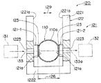
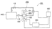
図1及び図2に示すように、本実施形態の流体濃度測定用フローセル120は、基本的構成として、管110と、投受光用部材121と、保持部材122とを備え、図5に示す上記実施形態の流体濃度測定装置101におけるフローセル部分を構成する。尚、上述したようにフローセルとは、試料液体へ光線を照射するために用いる光透過性材料にて形成された流路部分である。
First, the fluid concentration measurement flow cell will be described.
As shown in FIGS. 1 and 2, the fluid concentration
上記管110は、後述する流体濃度測定装置101において、被測定物を含む流体115が流れる配管114と同一の管であり、被測定物を含む流体の種類、使用条件等に応じて、種々の材質及び寸法にてなるものを適宜選択することができる。本実施形態では、管110は、可塑性で透光性の材質からなり、一例として、フッ素樹脂にてなり、1/4〜1インチ程度の直径を有する。尚、フッ素樹脂材としては、例えばパーフルオロ樹脂(PFA)、ポリ4フッ化エチレン(PTFE)、又はフッ化エチレンプロピレン(FEP)等が好ましい。
The
上記投受光用部材121は、透光性の材料にてなる一対の投光用部材121−1及び受光用部材121−2からなり、管110の外側から管110に交差する交差方向129に沿って管110を挟み、かつ管110に密着して管110と一体的に形成される部材である。このように設置される投受光用部材121は、管110内の流体における被測定物の物性を測定するための測定光133を通過させる。本実施形態では、上記交差方向129は、管110の軸方向111に対して、測定光133の光軸133aが直交する方向であり、図2に示すように、投光用部材121−1と受光用部材121−2とは、管110の軸方向111において同位置で互いに対向しかつ平行に配置される。しかしながら、交差方向129は、上記直交方向に限定するものではなく、投光用部材121−1と受光用部材121−2とが管110の軸方向111において互いにずれて配置され、測定光133の光軸133aと軸方向111とが90度以外の角度で交差するように構成されてもよい。
The light projecting / receiving
又、従来のフローセルの場合と同様に、当該流体濃度測定用フローセル120においても、投受光用部材121間の距離、つまり投光用部材121−1と受光用部材121−2との間の部材間距離126は、変動しないことが測定精度上、非常に重要である。そこで本実施形態では、部材間距離126を不変に維持するため、管110への投受光用部材121の取り付け方法を工夫するとともに、保持部材122を設けている。これらについては、追って詳しく説明する。
As in the case of the conventional flow cell, also in the
測定光133は、可視領域、赤外領域、及び紫外領域の少なくとも一つの領域における光であり、測定光133の種類に応じて、投受光用部材121の材質が選択される。本実施形態では、投受光用部材121は、石英、サファイヤ、例えばBK7と呼ばれホウ素と珪素とを含む光学ガラス材、フッ化カルシウム、又はフッ素樹脂等の材質からなる。尚、フッ素樹脂材としては、例えばパーフルオロ樹脂(PFA)、ポリ4フッ化エチレン(PTFE)、又はフッ化エチレンプロピレン(FEP)等が好ましい。
The
上述の各材料において、投受光用部材121用として、最も汎用的にはBK7が用いられる。BK7は可視領域及び近赤外領域の光を透過する。一方、可視領域より短波長側の紫外領域、及び近赤外領域より長波長側の中赤外領域の光を扱う場合には、BK7以外の光学部材を使う必要がある。紫外領域までも測定できる材料して石英がある。石英は、紫外領域、可視領域、及び近赤外領域の光を透過することができる。尚、フッ酸に対して溶解する短所がある。フッ酸に対して耐久性がある材料としてサファイアがある。サファイアは、紫外領域、可視領域、及び近赤外領域の光を透過することができる。フッ化カルシウムは、紫外領域、可視領域、近赤外領域、及び中赤外領域まで、広範囲の光を透過することができるが、水に対して溶解する特性があり、湿度が多い環境下では好ましくない。又、フッ素樹脂材は、光透過性が上述の各材料に比べて劣る。
In each of the above materials, BK7 is most commonly used for the light projecting / receiving
尚、後述するように、管110に投受光用部材121を密着させる方法の一つとして、融着させる方法がある。この場合、両者の性状が同一又は近似する方が良好な融合性を得られることから、管110が例えばフッ素樹脂からなるときには、投受光用部材121もフッ素樹脂からなるのが好ましい。
As will be described later, as one method for bringing the light projecting / receiving
又、投受光用部材121は、板状や、図4に示すようにレンズ状の形状を採ることができる。板形状は、衝撃等の外乱による部材間距離126への影響が少ないことから好ましい。尚、図4では凸レンズを図示しているが、凹レンズを用いることもできる。又、本実施形態では、投光用部材121−1及び受光用部材121−2は、共に板状の部材で同形状のものを用いているが、両者で異ならせることもできる。
Further, the light projecting / receiving
又、投受光用部材121の大きさは、測定光133を透過させるという投受光用部材121の機能から、最低限、測定光133の通過に必要な寸法を確保すればよく、該寸法は、例えば約5mmである。よって、投受光用部材121は、約5mm角以上、あるいは直径約5mm以上で、管110の直径にほぼ相当するまでの大きさを有する。又、投受光用部材121が板形状であるとき、その厚みは、管110の外径と肉厚により、管110を投受光用部材121にて挟持したときの圧力が変わるため、それに耐えうる厚さにする必要がある。但し、厚さを増すほど減光量が増すため、適宜な厚みが選択される。尚、本実施形態では、例えば2〜5mmである。
In addition, the size of the light projecting / receiving
投受光用部材121を管110へ密着させて管110と一体的に形成させる方法として、図1に示すように密着向上剤123を用いる方法と、図3に示すように投受光用部材121と管110とを融着させ融着部分124を形成する方法とがある。上記密着向上剤123は、管110の外面110aと、投受光用部材121との間に介在し、管外面110aと投受光用部材121との密着性を向上させかつ管110に投受光用部材121を固定させる物質である。一例として、エポキシ系、シリコン系、及びシアノアクリレート系等の接着剤が使用可能である。尚、図1及び図3において、密着向上剤123及び融着部分124は、明瞭化のため実際より誇張して図示している。
As a method for bringing the light projecting / receiving
又、上述のように投受光用部材121を測定光133が透過することから、密着向上剤123及び融着部分124に気泡が混在すると光の屈折や散乱等が生じ測定精度を劣化させる。よって、いずれの方法においても脱泡することが肝要となる。例えば、撹拌脱泡装置を用いて脱泡を行うことができ、撹拌脱泡装置としては例えば日本国特許第2711964号、3213735号に開示されるような、例えば遠心力作用を利用して脱泡を行う装置が使用可能である。
尚、投受光用部材121を管110と一体的に形成させるための具体的方法については後述する。
Further, as described above, since the
A specific method for forming the light projecting / receiving
上記保持部材122は、投受光用部材121に取り付けられ、一対の投受光用部材121間の部材間距離126を管110の変形に関係なく常に一定に保持する部材である。尚、本実施形態では、部材間距離126の基準位置を、対向する各投受光用部材121の対向面としているが、これに限定するものではなく、投受光用部材121における任意の位置を基準に採ることができる。
上述したように、フローセルにおいて、部材間距離126が変動しないことは、測定精度上、非常に重要である。一方、管110は、内部を流れる流体の温度や圧力等の影響により変形する。したがって、たとえ、上述のように投受光用部材121が管110と一体的に形成されたとしても、投受光用部材121を支持する部材が存在しなければ、管110の上記変形に伴い、部材間距離126も変動してしまう。そこで、管110の変形に関係なく部材間距離126を常に一定に維持する保持部材122が投受光用部材121に取り付けられる。
The holding
As described above, in the flow cell, it is very important in terms of measurement accuracy that the
保持部材122は、図1に示すようにコ字状の断面にてなり管110に沿って延在する部材であり、取付部材1221と、連結部材1222とを有し、取付部材1221と連結部材1222とが一体的に成形されて保持部材122を構成する。このような保持部材122は、上述のように部材間距離126を管110の変形に関係なく常に一定に保持する機能を果たすため、剛性を有する部材であって、例えばアルミニウムやステンレス等の金属材等から作製される。
As shown in FIG. 1, the holding
取付部材1221は、管110を挟むように互いに対向しかつ平行に配置された、一対の平板形状にてなる部材であり、互いの対向面1221aにはそれぞれ投受光用部材121が固定される。尚、該固定は、取付部材1221に対して投受光用部材121が容易に移動しない程度の押圧力にて取付部材1221で投受光用部材121を挟持する方法で行う。さらに、投受光用部材121において測定光133が通過しない部分に接着剤を塗布して取付部材1221に固定してもよい。又、固定に当たり、取付部材1221と投受光用部材121との摩擦力を増し投受光用部材121のずれを防ぐために、例えば取付部材1221に溝等を形成するのが好ましい。
各取付部材1221には、投受光用部材121に対応する部分に、取付部材1221をその厚み方向に貫通し測定光133の光軸133aを通過させるための貫通穴1223が形成されている。貫通穴1223の断面形状は、特定されるものではなく、例えば円形で、その直径が最低5mm程度にてなる円形形状とすることができる。勿論、貫通穴1223の大きさは、投受光用部材121よりも小さい。
The
Each
又、投受光用部材121がレンズ形状であるとき、取付部材1221の対向面1221aには、レンズ表面の形状に応じた凹凸が形成されていてもよい。例えば、投受光用部材121が図4に示すような凸レンズであるとき、対向面1221aには、レンズ表面の形状に応じた凹部が形成されていてもよい。
Further, when the light projecting / receiving
連結部材1222は、取付部材1221の対向面1221aを対向させかつ平行に配置するように各取付部材1221を連結する部材であり、部材間距離126を規定し、かつ規定した部材間距離126の変動を禁止する部材である。管110の径寸法によるが、部材間距離126は、本実施形態では約2〜20mmである。尚、本実施形態では、図1に示すように、取付部材1221と連結部材1222とは一体的に成形されていることから、保持部材122では部材間距離126を変更することはできない。しかしながら、例えば、連結部材1222を伸縮可能な構造としたり、取付部材1221の対向面1221a間の距離を変更可能なように一方の取付部材1221を連結部材1222に対して移動可能な構造としたりすることで、部材間距離126を可変とした構造を有する保持部材122とすることもできる。但し、部材間距離126を可変とした構造を有する場合でも、一旦規定した部材間距離126は、管110の変形に応じて変動することはない。
The connecting
以上説明した構成により、流体濃度測定用フローセル120が形成される。
With the configuration described above, the fluid concentration
以下に、投受光用部材121を管110と一体的に形成させる、本実施形態での方法について図6から図10を参照して説明する。尚、ここでは、板状の投受光用部材121を例に採るが、どのような形状の投受光用部材121についても適用可能である。
Hereinafter, a method according to this embodiment in which the light projecting / receiving
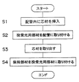
図6のステップS1では、当該流体濃度測定用フローセル120を構成する管110を用意し、当該管110内へ、図7に示すように距離規定用芯材190を挿入する。該距離規定用芯材190は、上述したように管110に対して対向して配置される一対の投受光用部材121の部材間距離126を規定するための部材であり、又、以下に説明するように投受光用部材121を管110に押圧するときの台座となる部材である。このような距離規定用芯材190は、部材間距離126に対応した大きさ、及び一対の投受光用部材121を対向させて平行に配置させる形状、即ち、角材であって、互いに平行にて対向する2つの平面190a,190bを有し、アルミニウムやステンレス等の金属材や、ガラス等にてなる。対向する2つの平面190a,190b間の距離は、部材間距離126−αの寸法にてなる。ここでαは、密着向上剤123を介在させるときには、管110の管厚と密着向上剤123の厚みとの加算値を2倍した値となる。又、以下に説明するように、効果的な管110の加熱が可能なように、距離規定用芯材190は、管110の軸方向111に沿って貫通穴190cを有する、例えば図示するような筒状の角材であってもよい。
In step S1 of FIG. 6, a
尚、投受光用部材121がレンズ形状である場合、距離規定用芯材190の上記平面190a,190bには、レンズ表面の形状に応じた凹凸が形成されていてもよい。例えば、投受光用部材121が図4に示すような凸レンズであるとき、平面190a,190bには、レンズ表面の形状に応じた凹部が形成されていてもよい。
When the light projecting / receiving
ステップS2では、例えば管110内へ約200〜360℃の熱風を吹き込み、管110を軟化させる。又、該軟化動作と並行して、各投受光用部材121における管110の外面110aとの接触面121aに、若しくは該接触面121aが押圧される管110の外面110aに、若しくはそれらの両方に、上記密着向上剤123を塗布する。該塗布後、上記軟化動作を継続しながら、図8に示すように、距離規定用芯材190の上記平面190a,190bに対向するように接触面121aを配置し、各投受光用部材121にて管110を挟む。このとき、上述したように、接触面121aと管外面110aとの間に気泡を封止しないようにする。挟持後、プレス機にて、平面190a,190bに直交する押圧方向191に沿って各投受光用部材121を管110の外面110aに押圧する。本実施形態では、一例として、押圧力0.1〜1MPa程度で、2〜5分程度にて、押圧動作を行う。尚、本実施形態では、押圧方向191は、上述の交差方向129に平行な方向となる。
In step S <b> 2, for example, hot air of about 200 to 360 ° C. is blown into the
該押圧動作により、各投受光用部材121の接触面121aと管110の外面110aとが密着しかつ各投受光用部材121が管110と一体的に形成される。
密着向上剤123を用いて上記一体的形成を行う場合、以下に説明する融着の場合に比べて簡便に行うことができる。
By the pressing operation, the
When the integral formation is performed using the
一方、投受光用部材121を管110に融着させる場合、管110のみを溶融させる、若しくは投受光用部材121のみを溶融させる、若しくは管110及び投受光用部材121の両方を溶融させる、の3つの形態が考えられる。いずれの形態を採るかによって、管軟化温度及び押圧力は変動するが、一般的に、密着向上剤123を使用する上述の場合に比べて融着させる場合には管軟化温度及び押圧力は大きくなる。例えば管110のみを溶融させて投受光用部材121を管110に融着させる場合、管110の軟化は、例えば管110内へ約200〜360℃の熱風を吹き込むことでなされ、各投受光用部材121の管110への押圧動作は、押圧力0.1〜1MPa程度で、2〜5分程度にて行う。
尚、融着にて上記一体的形成を行う場合においても、融着部分124に気泡が封止されないようにする必要がある。
On the other hand, when the light projecting / receiving
Even in the case where the integral formation is performed by fusion, it is necessary to prevent bubbles from being sealed in the
このように融着にて上記一体的形成を行う場合、上述の、密着向上剤123を用いる場合に比べて投受光用部材121と管110とを、より一体的に形成することができる。又、接合部分では投受光用部材121及び管110以外の物質を含まないことから、当該接合部分を通過する測定光133への影響を考慮する必要もない。よって、密着向上剤123を用いる場合に比べて、測定精度をより向上させることができる。
Thus, when performing the above-mentioned integral formation by fusion, the light projecting / receiving
上記一体的形成後、ステップS3では、上記軟化動作を停止し、図9に示すように、管110内から距離規定用芯材190を取り出す。
After the integral formation, in step S3, the softening operation is stopped, and the
次のステップ4では、図10に示すように、管110と一体的に形成された一対の投受光用部材121における部材間距離126を固定するため、上記保持部材122を投受光用部材121に取り付ける。尚、本実施形態では、上述のように、管110内から距離規定用芯材190を取り出した後、ステップS4を実行しているが、ステップS3では上記軟化動作の停止のみを行い、距離規定用芯材190の取り出しを行うことなくステップS4に移行してもよい。そして、ステップS4の終了後、管110内から距離規定用芯材190を取り出してもよい。
以上説明した製造方法により、流体濃度測定用フローセル120が形成される。
In the next step 4, as shown in FIG. 10, the holding
The fluid concentration
上述した構成にてなる流体濃度測定用フローセル120では、特に、(1)被測定物を含む流体が流れる配管と同一の管110を用いる点、(2)該管110の外面110aに対して測定用部材を取り付けた構成であり管110の内側である流路部分には何ら測定用部材を設けていない点、(3)投受光用部材121を管110と一体的に形成した点、及び(4)管110と一体的に形成された投受光用部材121に対して部材間距離126の変動を禁止する保持部材を取り付けた点の特徴的な構成を有する。このような流体濃度測定用フローセル120によれば、特に上記(3)及び(4)の構成により、流体の温度や圧力等により管110が変形した場合でも、部材間距離126が変動することはなくなる。したがって、流体濃度測定用フローセル120は、従来に比べて高精度にて流体内の被測定物の濃度測定が可能なように寄与する。
In the fluid concentration
又、上記(1)及び(2)の構成により、本実施形態の流体濃度測定用フローセル120を設置したシステムにおいても、流体濃度測定用フローセル120部分にて、流体の圧力損失が発生することはなく、又、液溜まりが生じる箇所も存在しないことになる。したがって、例えばフローセル部分における流体の圧力損失が当該システムの全体に悪影響を与えることはない。又、フローセルの一部の構成部分が流体内へ溶出することはなく、流体濃度測定用フローセル120によれば、適用可能な流体が限定されることもない。又、液溜まりが生じないことから、例えば配管洗浄動作等も容易に行うことができる。
In addition, with the above-described configurations (1) and (2), even in a system in which the fluid concentration
上述のように構成される流体濃度測定用フローセル120を備えて、流体内の被測定物の濃度を測定する流体濃度測定装置を構成することができる。図5に示す流体濃度測定装置101は、配管114と、上述の流体濃度測定用フローセル120と、該流体濃度測定用フローセル120を有する検出部130と、処理部140と、濃度測定部150と、制御部160とを備える。制御部160は、検出部130、及び濃度測定部150等の動作を制御する。尚、上述の流体濃度測定用フローセル120を備えた流体濃度測定装置の基本的構成としては、配管114と、流体濃度測定用フローセル120と、濃度測定部150と、上記検出部130に備わり下記の受光部132とを備えればよい。
The fluid concentration measuring
配管114は、流体濃度測定用フローセル120に備わる管110と同一の材質、形状、及びサイズにてなる配管であり、本実施形態では、処理部140から送出され、流体濃度測定用フローセル120を通過した流体115が再び処理部140に戻るように循環系を構成している。該循環系には、流体115を循環させるためのポンプが備わる。勿論、このような循環系を構成せず、非循環系の一部に流体濃度測定用フローセル120を設置することもできる。
The
検出部130は、上述の流体濃度測定用フローセル120と、投光部131と、受光部132とを有する。
投光部131は、流体濃度測定用フローセル120における投光用部材121−1に対応して配置され、例えばタングステン・ハロゲンランプからなる光源から測定光133を発する。尚、投光部131は、上記光源にて発生した測定光133が流体濃度測定用フローセル120に備わる貫通穴1223を通過可能とするための適宜な投光側光学系を有する。
The
The
受光部132は、流体濃度測定用フローセル120における受光用部材121−2に対応して配置され、投光部131から発射され、貫通穴1223、投光用部材121−1、管110、流体115、受光用部材121−2、及び貫通穴1223を通過した測定光133を受光する。尚、受光部132には、受光素子と、該受光素子に上記測定光133を集光させるための適宜な受光側光学系とが備わる。又、受光部132は、濃度測定部150と電気的に接続され、受光した測定光133の強度に応じた電気信号を濃度測定部150へ送出する。
The
処理部140は、被測定物に対応して設置される部分であり、例えば半導体ウエハの洗浄液の濃度測定を行う場合には、半導体ウエハの洗浄工程部である。
The
濃度測定部150は、受光部132から供給される電気信号に基づいて、配管114内を流れる流体115における被測定物の濃度を求める。濃度決定方法は、例えば、上記電気信号と濃度との既知の関係を利用する方法等、公知の種々の方法を採ることができる。
The
本発明は、例えば半導体や液晶表示装置等の製造工程に使用される流体の濃度測定用として配管に取り付けられる流体濃度測定用フローセル、及び上記フローセルを備えた流体濃度測定装置に適用可能である。 The present invention is applicable to, for example, a fluid concentration measurement flow cell attached to a pipe for measuring the concentration of a fluid used in a manufacturing process of a semiconductor, a liquid crystal display device, and the like, and a fluid concentration measurement apparatus including the flow cell.
101…流体濃度測定装置、110…管、115…流体、
120…流体濃度測定用フローセル、121…投受光用部材、
121−2…受光用部材、122…保持部材、123…密着向上剤、
126…部材間距離、129…交差方向、132…受光部、133…測定光、
150…濃度測定部、190…距離規定用芯材。
101 ... Fluid concentration measuring device, 110 ... Tube, 115 ... Fluid,
120 ... Flow cell for measuring fluid concentration, 121 ... Projecting / receiving member,
121-2: light receiving member, 122 ... holding member, 123 ... adhesion improver,
126 ... Distance between members, 129 ... Crossing direction, 132 ... Light receiving part, 133 ... Measuring light,
150 ... concentration measuring unit, 190 ... core for distance regulation.
Claims (11)
上記管に交差する方向(129)から上記管を挟み、かつ上記管に密着して上記管と一体的に形成され、上記流体の物性測定用の測定光(133)を通過させる一対の投受光用部材(121)と、
上記投受光用部材に取り付けられ、上記一対の投受光用部材間の部材間距離(126)を上記管の変形に関係なく常に一定に保持する保持部材(122)と、
を備え、
上記投受光用部材は上記管に融着して固定される、
ことを特徴とするフローセル。 A pipe (110) made of a plastic and translucent material and through which the fluid (115) of the object to be measured flows;
A pair of light projecting and receiving light that sandwiches the tube from the direction (129) intersecting the tube and is in close contact with the tube and is integrally formed with the tube and allows the measurement light (133) for measuring the physical properties of the fluid to pass therethrough. Member (121);
A holding member (122) that is attached to the light projecting / receiving member and that holds the inter-member distance (126) between the pair of light projecting / receiving members constant at all times regardless of the deformation of the tube;
With
The light projecting / receiving member is fused and fixed to the tube;
A flow cell characterized by that.
上記管に交差する方向(129)から上記管を挟み、かつ上記管に密着して上記管と一体的に形成され、上記流体の物性測定用の測定光(133)を通過させる一対の投受光用部材(121)と、
上記投受光用部材に取り付けられ、上記一対の投受光用部材間の部材間距離(126)を上記管の変形に関係なく常に一定に保持する保持部材(122)と、
を備え、
上記投受光用部材は、レンズ形状又は板形状にてなり互いに平行に対向して配置され、フッ素樹脂からなる、
ことを特徴とするフローセル。 A pipe (110) made of a plastic and translucent material and through which the fluid (115) of the object to be measured flows;
A pair of light projecting and receiving light that sandwiches the tube from the direction (129) intersecting the tube and is in close contact with the tube and is integrally formed with the tube and allows the measurement light (133) for measuring the physical properties of the fluid to pass therethrough. Member (121);
A holding member (122) that is attached to the light projecting / receiving member and that holds the inter-member distance (126) between the pair of light projecting / receiving members constant at all times regardless of the deformation of the tube;
With
The light projecting / receiving member is formed in a lens shape or a plate shape and is arranged to face each other in parallel, and is made of a fluororesin.
A flow cell characterized by that.
上記フローセルに備わる管(110)、及び上記管を流れる流体(115)を透過し上記フローセルに備わる上記投受光用部材の内の受光用部材(121−2)を透過した測定光(133)を受光する受光部(132)と、 The measurement light (133) transmitted through the pipe (110) provided in the flow cell and the light receiving member (121-2) among the light projecting and receiving members provided in the flow cell through the fluid (115) flowing through the pipe. A light receiving unit (132) for receiving light;
上記受光部と電気的に接続され、受光部にて検出した上記測定光の強度に基づいて上記被測定物の濃度を求める濃度測定部(150)と、 A concentration measuring unit (150) that is electrically connected to the light receiving unit and obtains the concentration of the object to be measured based on the intensity of the measurement light detected by the light receiving unit;
を備えたことを特徴とする流体濃度測定装置。 A fluid concentration measuring device comprising:
上記管を軟化させると伴に、上記管の外側から上記距離規定用芯材に対向して上記管に交差する方向(129)に沿って上記投受光用部材で上記管を挟み、かつ上記投受光用部材を上記管に押圧して上記投受光用部材を上記管に密着させかつ脱泡状態にて融着させて上記管と一体的に形成し、 As the tube is softened, the tube is sandwiched by the light projecting and receiving members along the direction (129) that faces the distance-defining core from the outside of the tube and intersects the tube. Pressing the light receiving member against the tube, bringing the light projecting and receiving member into close contact with the tube and fusing in a defoamed state, and integrally forming the tube,
上記形成後、上記部材間距離を上記管の変形に関係なく常に一定に保持するための保持部材(122)を上記投受光用部材に取り付ける、 After the formation, a holding member (122) for holding the distance between the members constant at all times regardless of the deformation of the tube is attached to the light projecting / receiving member.
ことを特徴とするフローセルの製造方法。 A manufacturing method of a flow cell characterized by the above.
上記管を軟化させると伴に、上記管の外側から上記距離規定用芯材に対向して上記管に交差する方向(129)に沿って上記投受光用部材で上記管を挟み、かつ上記投受光用部材を上記管に押圧して上記投受光用部材を上記管に密着させて上記管と一体的に形成し、 As the tube is softened, the tube is sandwiched by the light projecting and receiving members along the direction (129) that faces the distance-defining core from the outside of the tube and intersects the tube. The light receiving member is pressed against the tube, the light projecting / receiving member is brought into close contact with the tube, and formed integrally with the tube,
上記形成後、上記部材間距離を上記管の変形に関係なく常に一定に保持するための保持部材(122)を上記投受光用部材に取り付け、 After the formation, a holding member (122) for always holding the distance between the members constant regardless of the deformation of the tube is attached to the light projecting and receiving member.
上記投受光用部材は、レンズ形状又は板形状にてなり互いに平行に対向して配置され、フッ素樹脂からなる、 The light projecting / receiving member is in the shape of a lens or a plate and is disposed facing each other in parallel, and is made of a fluororesin.
ことを特徴とするフローセルの製造方法。 A manufacturing method of a flow cell characterized by the above.
Priority Applications (1)
| Application Number | Priority Date | Filing Date | Title |
|---|---|---|---|
| JP2005051280A JP4677251B2 (en) | 2005-02-25 | 2005-02-25 | Flow cell, flow cell manufacturing method, and fluid concentration measuring apparatus |
Applications Claiming Priority (1)
| Application Number | Priority Date | Filing Date | Title |
|---|---|---|---|
| JP2005051280A JP4677251B2 (en) | 2005-02-25 | 2005-02-25 | Flow cell, flow cell manufacturing method, and fluid concentration measuring apparatus |
Publications (2)
| Publication Number | Publication Date |
|---|---|
| JP2006234663A JP2006234663A (en) | 2006-09-07 |
| JP4677251B2 true JP4677251B2 (en) | 2011-04-27 |
Family
ID=37042468
Family Applications (1)
| Application Number | Title | Priority Date | Filing Date |
|---|---|---|---|
| JP2005051280A Active JP4677251B2 (en) | 2005-02-25 | 2005-02-25 | Flow cell, flow cell manufacturing method, and fluid concentration measuring apparatus |
Country Status (1)
| Country | Link |
|---|---|
| JP (1) | JP4677251B2 (en) |
Cited By (1)
| Publication number | Priority date | Publication date | Assignee | Title |
|---|---|---|---|---|
| KR101744955B1 (en) * | 2016-11-28 | 2017-06-09 | 주식회사 프레시즘 | Sensor module in apparatus for producing sterilized water using chlorine dioxide |
Families Citing this family (11)
| Publication number | Priority date | Publication date | Assignee | Title |
|---|---|---|---|---|
| TW200944776A (en) | 2008-03-04 | 2009-11-01 | Kurashiki Boseki Kk | Total reflection attenuation type far-ultraviolet spectroscopy and concentration measurement device using the spectroscopy |
| KR20130054240A (en) * | 2010-03-04 | 2013-05-24 | 유니센서 에이/에스 | Flexible sample container |
| US8907312B2 (en) | 2010-08-20 | 2014-12-09 | Bio-Rad Laboratories, Inc. | Cytometry system with solid numerical-aperture-increasing lens |
| JP2013148521A (en) * | 2012-01-20 | 2013-08-01 | Sumitomo Electric Ind Ltd | Sample measuring cell, physical property measurement device, and physical property measurement method |
| JP6264741B2 (en) * | 2013-04-16 | 2018-01-24 | 横河電機株式会社 | Spectroscopic analyzer |
| JP6249886B2 (en) * | 2014-06-11 | 2017-12-20 | 株式会社堀場製作所 | Optical measuring cell and optical analyzer |
| JP6443619B2 (en) * | 2014-11-26 | 2018-12-26 | 横河電機株式会社 | Sample measuring device |
| JP6503230B2 (en) | 2015-05-29 | 2019-04-17 | ニプロ株式会社 | Transmitted light intensity measurement unit |
| JP2022017606A (en) * | 2018-10-25 | 2022-01-26 | 株式会社 堀場アドバンスドテクノ | Concentration sensor |
| CN113376125A (en) * | 2021-06-16 | 2021-09-10 | 许闯 | Car glass luminousness check out test set |
| JP7250978B1 (en) * | 2022-04-19 | 2023-04-03 | ニプロ株式会社 | Fluid concentration measuring device |
Citations (6)
| Publication number | Priority date | Publication date | Assignee | Title |
|---|---|---|---|---|
| JPS5372566U (en) * | 1976-11-19 | 1978-06-17 | ||
| JPS60176163U (en) * | 1984-05-01 | 1985-11-21 | 株式会社島津製作所 | Sheath flow cell device |
| JPH05196602A (en) * | 1992-01-20 | 1993-08-06 | Hitachi Ltd | Capillary electrophoretic column |
| JPH0763681A (en) * | 1993-08-27 | 1995-03-10 | Calsonic Corp | Degradation detection apparatus for oil |
| JPH09264845A (en) * | 1996-03-28 | 1997-10-07 | Tokimec Inc | Absorptiometer |
| JP2003065952A (en) * | 2001-08-24 | 2003-03-05 | Kosu:Kk | Dissolved-ozone concentration meter |
-
2005
- 2005-02-25 JP JP2005051280A patent/JP4677251B2/en active Active
Patent Citations (6)
| Publication number | Priority date | Publication date | Assignee | Title |
|---|---|---|---|---|
| JPS5372566U (en) * | 1976-11-19 | 1978-06-17 | ||
| JPS60176163U (en) * | 1984-05-01 | 1985-11-21 | 株式会社島津製作所 | Sheath flow cell device |
| JPH05196602A (en) * | 1992-01-20 | 1993-08-06 | Hitachi Ltd | Capillary electrophoretic column |
| JPH0763681A (en) * | 1993-08-27 | 1995-03-10 | Calsonic Corp | Degradation detection apparatus for oil |
| JPH09264845A (en) * | 1996-03-28 | 1997-10-07 | Tokimec Inc | Absorptiometer |
| JP2003065952A (en) * | 2001-08-24 | 2003-03-05 | Kosu:Kk | Dissolved-ozone concentration meter |
Cited By (1)
| Publication number | Priority date | Publication date | Assignee | Title |
|---|---|---|---|---|
| KR101744955B1 (en) * | 2016-11-28 | 2017-06-09 | 주식회사 프레시즘 | Sensor module in apparatus for producing sterilized water using chlorine dioxide |
Also Published As
| Publication number | Publication date |
|---|---|
| JP2006234663A (en) | 2006-09-07 |
Similar Documents
| Publication | Publication Date | Title |
|---|---|---|
| JP4677251B2 (en) | Flow cell, flow cell manufacturing method, and fluid concentration measuring apparatus | |
| JP6961039B2 (en) | Dispenser for analyzer | |
| JP3301737B2 (en) | Refractometer | |
| JP5714977B2 (en) | Optical measuring device | |
| FI113566B (en) | The refractometer | |
| JP5915451B2 (en) | Flow cell | |
| JP2007192638A (en) | Gas sensor | |
| JP6666736B2 (en) | Pressure detector | |
| JP2012154712A (en) | Flow sensor and resist application device using the same | |
| JP7060409B2 (en) | Manufacturing method of optical measuring cell, optical analyzer, and optical measuring cell | |
| WO2009110270A1 (en) | Microchip and method of manufacturing same | |
| JP2012204813A (en) | Bubble detection method, resist application method, and resist application device | |
| WO2018037536A1 (en) | Flow cell | |
| JP2015135251A (en) | Solution analyzer | |
| CN112240803A (en) | Temperature sensing device and temperature sensing system using same | |
| JP2012202971A (en) | Flow sensor and resist coating device using the same | |
| CN208488186U (en) | A kind of temperature sensing device based on photonic crystal fiber | |
| JP5868626B2 (en) | Optical measuring cell and optical analyzer | |
| JP5199083B2 (en) | Flow path sensor and tube fixture used therefor | |
| US10989581B2 (en) | Sensor for a thermal, flow measuring device having sensor element spacing protrusions | |
| TWI729739B (en) | Temperature detection device | |
| JP2020118633A (en) | Thermal type flowmeter | |
| JP6578391B2 (en) | Semiconductor manufacturing equipment component, semiconductor manufacturing equipment component temperature distribution measuring method, and semiconductor manufacturing equipment temperature distribution measuring device | |
| JP4388844B2 (en) | Hydrogen peroxide gas condensation detection device and hydrogen peroxide gas condensation management system | |
| JP2022185657A (en) | optical analyzer |
Legal Events
| Date | Code | Title | Description |
|---|---|---|---|
| A621 | Written request for application examination |
Free format text: JAPANESE INTERMEDIATE CODE: A621 Effective date: 20071218 |
|
| RD03 | Notification of appointment of power of attorney |
Free format text: JAPANESE INTERMEDIATE CODE: A7423 Effective date: 20071218 |
|
| A977 | Report on retrieval |
Free format text: JAPANESE INTERMEDIATE CODE: A971007 Effective date: 20100722 |
|
| A131 | Notification of reasons for refusal |
Free format text: JAPANESE INTERMEDIATE CODE: A131 Effective date: 20100727 |
|
| A521 | Request for written amendment filed |
Free format text: JAPANESE INTERMEDIATE CODE: A523 Effective date: 20100921 |
|
| A131 | Notification of reasons for refusal |
Free format text: JAPANESE INTERMEDIATE CODE: A131 Effective date: 20101116 |
|
| A521 | Request for written amendment filed |
Free format text: JAPANESE INTERMEDIATE CODE: A523 Effective date: 20110105 |
|
| TRDD | Decision of grant or rejection written | ||
| A01 | Written decision to grant a patent or to grant a registration (utility model) |
Free format text: JAPANESE INTERMEDIATE CODE: A01 Effective date: 20110125 |
|
| A01 | Written decision to grant a patent or to grant a registration (utility model) |
Free format text: JAPANESE INTERMEDIATE CODE: A01 |
|
| A61 | First payment of annual fees (during grant procedure) |
Free format text: JAPANESE INTERMEDIATE CODE: A61 Effective date: 20110131 |
|
| FPAY | Renewal fee payment (event date is renewal date of database) |
Free format text: PAYMENT UNTIL: 20140204 Year of fee payment: 3 |
|
| R150 | Certificate of patent or registration of utility model |
Ref document number: 4677251 Country of ref document: JP Free format text: JAPANESE INTERMEDIATE CODE: R150 Free format text: JAPANESE INTERMEDIATE CODE: R150 |
|
| R250 | Receipt of annual fees |
Free format text: JAPANESE INTERMEDIATE CODE: R250 |
|
| R250 | Receipt of annual fees |
Free format text: JAPANESE INTERMEDIATE CODE: R250 |
|
| R250 | Receipt of annual fees |
Free format text: JAPANESE INTERMEDIATE CODE: R250 |
|
| R250 | Receipt of annual fees |
Free format text: JAPANESE INTERMEDIATE CODE: R250 |
|
| R250 | Receipt of annual fees |
Free format text: JAPANESE INTERMEDIATE CODE: R250 |
|
| R250 | Receipt of annual fees |
Free format text: JAPANESE INTERMEDIATE CODE: R250 |
|
| R250 | Receipt of annual fees |
Free format text: JAPANESE INTERMEDIATE CODE: R250 |
|
| R250 | Receipt of annual fees |
Free format text: JAPANESE INTERMEDIATE CODE: R250 |
|
| R250 | Receipt of annual fees |
Free format text: JAPANESE INTERMEDIATE CODE: R250 |
|
| R250 | Receipt of annual fees |
Free format text: JAPANESE INTERMEDIATE CODE: R250 |
|
| R250 | Receipt of annual fees |
Free format text: JAPANESE INTERMEDIATE CODE: R250 |