JP2015135251A - Solution analyzer - Google Patents
Solution analyzer Download PDFInfo
- Publication number
- JP2015135251A JP2015135251A JP2014006016A JP2014006016A JP2015135251A JP 2015135251 A JP2015135251 A JP 2015135251A JP 2014006016 A JP2014006016 A JP 2014006016A JP 2014006016 A JP2014006016 A JP 2014006016A JP 2015135251 A JP2015135251 A JP 2015135251A
- Authority
- JP
- Japan
- Prior art keywords
- sample
- temperature
- heat exchanger
- optical system
- measurement optical
- Prior art date
- Legal status (The legal status is an assumption and is not a legal conclusion. Google has not performed a legal analysis and makes no representation as to the accuracy of the status listed.)
- Pending
Links
Images

Abstract
Description
本発明は、フローセルに流れる試料(溶液)を光学的に分析する溶液分析計に関し、例えば蛍光分光法を用いて試料の分析を行う溶液分析計に好適なものである。 The present invention relates to a solution analyzer that optically analyzes a sample (solution) flowing in a flow cell, and is suitable for a solution analyzer that analyzes a sample using, for example, fluorescence spectroscopy.
蛍光分光法による試料の分析では、試料をフローセルに導入し、予め設定された特定波長の光を励起光として照射し、励起された試料の蛍光を蛍光検出器で測定することで、試料中の測定対象成分の濃度を測定する。このとき、測定対象となる試料や成分の中には、蛍光強度の温度依存性の大きいものがあり、環境温度によって試料の温度が変動すると蛍光検出器などの測定光学系で検出される蛍光の強度が変動してしまい、適正な分析ができない。そのため、例えば下記特許文献1及び特許文献2では、フローセルに流入する前に熱交換器で試料の熱交換を行うと共に、フローセルを含む測定光学系と熱交換器を共通する温調機構で一定の温度に調整する。具体的には、測定光学系と熱交換器を熱的に接触させ、それらを一つの温調機構で一定温度に調整する。また、下記特許文献2では、更に蛍光検出器も同じ温調機構で一定の温度に調整するようにしている。
In analysis of a sample by fluorescence spectroscopy, the sample is introduced into a flow cell, irradiated with light of a specific wavelength set in advance as excitation light, and the fluorescence of the excited sample is measured with a fluorescence detector. Measure the concentration of the component to be measured. At this time, some samples and components to be measured have large temperature dependence of fluorescence intensity. When the temperature of the sample fluctuates due to environmental temperature, the fluorescence detected by the measurement optical system such as a fluorescence detector Intensity fluctuates and proper analysis is not possible. Therefore, for example, in Patent Document 1 and
試料の流量が小さい場合には、前記特許文献1や特許文献2のように、測定光学系と熱交換器を熱的に接触させて同時に温度調節しても試料の温度を一定に保持することができる。しかしながら、プロセス分析計などでは、試料の流量を小さくすることが困難であり、或いは洗浄水を通水するために或る程度の管径と流量を確保しなければならない。一般的に、熱交換器における試料の流量が大きいほど熱交換量が大きくなり、交換熱によって熱交換器の温度が変動する。このとき、熱交換器と測定光学系が熱的に接触していると、熱交換器の温度変動が測定光学系に伝導して測定光学系の温度が変動することから、試料の温度を高精度に一定にすることができなくなってしまう。そして、試料の温度が変動すると、適正な分析ができなくなってしまう。
When the flow rate of the sample is small, the temperature of the sample can be kept constant even if the measurement optical system and the heat exchanger are brought into thermal contact with each other and the temperature is adjusted at the same time as in Patent Document 1 and
本発明はこれらの諸問題を解決すべくなされたものであり、試料の流量が大きい場合であっても試料の温度を一定にすることができ、もって測定対象試料の適正な分析を可能とする溶液分析計を提供することを目的とするものである。 The present invention has been made to solve these various problems, and even when the flow rate of the sample is large, the temperature of the sample can be kept constant, thereby enabling appropriate analysis of the sample to be measured. The object is to provide a solution analyzer.
以上の課題を解決するため、本発明のある態様に係る溶液分析計は、フローセルに流れる試料を光学的に分析する溶液分析計であって、前記試料の熱交換を行う熱交換器と、前記熱交換器の温度を一定にする熱交換器用温調機構と、前記フローセルを含む測定光学系と、前記測定光学系の温度を一定にする測定光学系用温調機構と、を備えることを特徴とするものである。 In order to solve the above problems, a solution analyzer according to an aspect of the present invention is a solution analyzer that optically analyzes a sample flowing in a flow cell, the heat exchanger performing heat exchange of the sample, A temperature adjustment mechanism for a heat exchanger that makes the temperature of the heat exchanger constant, a measurement optical system that includes the flow cell, and a temperature adjustment mechanism for the measurement optical system that makes the temperature of the measurement optical system constant It is what.
なお、温調とは、温度調節を意味する。
また、この溶液分析計において、前記熱交換器と前記測定光学系とが熱的に分離されていることが望ましい。
また、この溶液分析計において、前記熱交換器用温調機構及び前記測定光学系用温調機構がペルチェ素子であることが望ましい。
In addition, temperature control means temperature control.
In this solution analyzer, it is desirable that the heat exchanger and the measurement optical system are thermally separated.
In this solution analyzer, it is preferable that the temperature adjustment mechanism for the heat exchanger and the temperature adjustment mechanism for the measurement optical system are Peltier elements.
而して、本発明の溶液分析計によれば、試料の熱交換を行う熱交換器は熱交換器用温調機構によって一定温度とされ、フローセルを含む測定光学系は測定光学系用温調機構によって一定温度とされるので、試料の流量が大きい場合であっても試料の温度を一定にすることができ、もって測定対象試料の適正な分析が可能となる。
また、熱交換器と測定光学系とを熱的に分離することにより、試料の流量が大きい場合に熱交換器の温度変動の影響を測定光学系が受けにくくなり、試料の温度をより一層一定にすることができ、もって測定対象試料の適正な分析が可能となる。
Thus, according to the solution analyzer of the present invention, the heat exchanger for exchanging the heat of the sample is kept at a constant temperature by the temperature adjustment mechanism for the heat exchanger, and the measurement optical system including the flow cell is the temperature adjustment mechanism for the measurement optical system. Therefore, even if the flow rate of the sample is large, the temperature of the sample can be kept constant, and thus the sample to be measured can be appropriately analyzed.
In addition, by thermally separating the heat exchanger and the measurement optical system, the measurement optical system is less susceptible to the effects of temperature fluctuations of the heat exchanger when the flow rate of the sample is large, and the sample temperature is made more constant. Therefore, it is possible to appropriately analyze the sample to be measured.
また、熱交換器用温調機構及び測定光学系用温調機構にペルチェ素子を用いることで、構成を容易にすることができる。 Moreover, a structure can be made easy by using a Peltier element for the temperature control mechanism for heat exchangers, and the temperature control mechanism for measurement optical systems.
図1は、本発明の溶液分析計の一実施形態を示す概略構成図である。本実施形態の溶液分析計は、試料の温度を一定にするための熱交換器1と、フローセル2を含む測定光学系3とを熱的に分離した状態で、具体的には非接触状態で備え、それらは断熱材4によって覆われ、且つ夫々断熱材4の内壁に接合されている。この断熱材4の外側から試料を導入し、断熱材4の外側に試料を送出する流路5は、熱交換器1から測定光学系3内のフローセル2を通過するように一連に形成されている。
FIG. 1 is a schematic configuration diagram showing an embodiment of a solution analyzer of the present invention. The solution analyzer of this embodiment is in a state in which the heat exchanger 1 for keeping the temperature of the sample constant and the measurement optical system 3 including the
この流路5は、熱交換器1の図示上方から熱交換器1の内部に接続され、熱交換器1の内部で蛇行するように通過して当該熱交換器1の図示下方から突出する。そして、測定光学系3の図示下方から内部に接続され、フローセル2を通過して測定光学系3の図示上方から突出する。試料は、溶液分析計の内部で、この順序に流れる。なお、熱交換器1から測定光学系3までの間の流路5は保温チューブ19によって覆われており、内部を通過する試料と断熱材4の内部空間空気との間で生じる熱交換を最小限にしている。流路5の材質としては、試料のコンタミネーション(汚染)を防止する観点からPTFE(ポリテトラフルオロエチレン)などを用いることが考えられる。
The
測定光学系3では、フローセル2を保持するフローセルホルダ6、フローセルホルダ6に保持されているフローセル6に特定波長の励起光を照射する光源7、フローセル6内の試料から生じる蛍光を検出する蛍光検出器8を備えている。なお、図1では、理解を容易にするために図示を省略しているが、光源7や蛍光検出器8は、周知のように、集光ミラーやスリット、解析格子などを備えて構成されている。また、図1では、光源7と蛍光検出器8とが直線上に配置されているが、実際には光源7と蛍光検出器8とは互いに直線上から90°ずれた位置に配置されている。
In the measurement optical system 3, a
前記熱交換器1の材質としては、例えば熱伝導性のよいアルミニウムブロックを用いることが考えられる。この熱交換器1には、熱交換器用温調機構としての熱交換器用ペルチェ素子9が接合され、その熱交換器用ペルチェ素子9は熱交換器1が接合されている断熱材4の壁部に埋設されている。ペルチェ素子は、周知のように、印加する電流の向きに応じて、例えば本実施形態では熱交換器1が接合されている面を加熱したり冷却したりすることが可能な半導体素子で、熱電素子とも呼ばれる。そして、断熱材4の外壁面に露出している熱交換器用ペルチェ素子9の外側面には熱交換器用放熱フィン10が接合され、この熱交換器用放熱フィン10に対向して熱交換器用放熱ファン11が配置されている。
As a material of the heat exchanger 1, it is conceivable to use, for example, an aluminum block having good thermal conductivity. The heat exchanger 1 is joined with a
熱交換器1には、熱交換器1自体の温度を検出するための熱交換器用温度センサ12が取付けられており、その出力は熱交換器用制御回路13に入力される。この熱交換器用温度センサ12としては、白金抵抗体、熱電対、サーミスタなどを用いることが考えられる。熱交換器用制御回路13では、熱交換器用温度センサ12で検出された熱交換器1の温度に基づいて、熱交換器用ペルチェ素子9への印加電流を制御すると共に、熱交換器用放熱ファン11の運転状態を制御し、熱交換器1の温度が予め設定された一定温度に保持されるようにする。その結果、流路5の熱交換器1からの出口で試料の温度を予め設定された一定温度又は一定温度領域に調節することが可能となる。
A heat
本実施形態では、前記測定光学系3にも測定光学系用温調機構としての測定光学系用ペルチェ素子14が接合され、その測定光学系ペルチェ素子14は測定光学系3が接合されている断熱材4の壁部に埋設されている。この測定光学系用ペルチェ素子14は、測定光学系3の構成部材の何れかに接合されていればよく、本実施形態ではフローセルホルダ6に接合されている。このフローセルホルダ6の材質としては、例えば熱伝導性のよいアルミニウムブロックを用いることが考えられる。また、フローセルホルダ6に保持されるフローセル2の材質としては、光透過性に優れ且つ熱伝導性のよい石英などを用いることが考えられる。
In the present embodiment, a measurement optical system
断熱材4の外壁面に露出している測定光学系用ペルチェ素子14の外側面には測定光学系用放熱フィン15が接合され、この測定光学用放熱フィン15に対向して測定光学用放熱ファン16が配置されている。また、フローセルホルダ6には、フローセルホルダ6自体の温度を検出するための測定光学系用温度センサ17が取付けられており、その出力は測定光学系用制御回路18に入力される。この測定光学系用温度センサ17としては、前記熱交換器用温度センサ12と同様に、白金抵抗体、熱電対、サーミスタなどを用いることが考えられる。測定光学系用制御回路18では、測定光学系用温度センサ17で検出されたフローセルホルダ6の温度に基づいて、測定光学系用ペルチェ素子14への印加電流を制御すると共に、測定光学系用放熱ファン16の運転状態を制御し、フローセルホルダ6の温度が予め設定された一定温度に保持されるようにする。その結果、フローセル2内における試料測定位置で試料の温度を予め設定された一定温度又は一定温度領域に調節することができる。
A measurement optical
このように予め設定された一定温度又は一定温度領域に調節されてフローセル2の試料測定位置に到達した試料には、光源7から特定波長の励起光が照射され、その蛍光が蛍光検出器12で検出される。試料の温度は一定温度又は一定温度領域であるので、蛍光検出器12で検出される蛍光強度は、試料の成分濃度を正確に反映し、検出された蛍光強度から試料の成分濃度を適正に検出することが可能となる。
The sample that has been adjusted to a preset constant temperature or a constant temperature region and has reached the sample measurement position of the
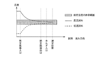
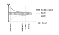
図2は、図1の溶液分析計において試料の流量が小さい場合の試料温度の説明図、図3は、図1の溶液分析計において試料の流量が大きい場合の試料温度の説明図である。共に、横軸には試料の流れ方向位置を、縦軸には温度をとり、測定位置における試料の設定温度の許容範囲を網掛けで表している。また、高温試料の温度変化を実線で、低温試料の温度変化を破線で示している。図2に示すように、試料の流量が小さい場合には熱交換器1の出口に到達するまでの間に試料の温度が許容範囲内に収まっており、勿論、測定位置でも許容範囲内に収まっている。一方、図3に示すように、試料の流量が大きい場合には熱交換器1の出口に到達するまでの間に試料の温度が許容範囲内に収まっていない。しかしながら、本実施形態では、測定光学系3を測定光学系用ペルチェ素子14で温度調節しているため、フローセルホルダ6に流入してからも試料の温度が変化し、測定位置では試料の温度が許容範囲内に収まっている。このことから、本実施形態の溶液分析計では、試料の成分濃度を適正に検出することができ、再現性の高い分析結果を得ることができる。
FIG. 2 is an explanatory diagram of sample temperature when the sample flow rate is small in the solution analyzer of FIG. 1, and FIG. 3 is an explanatory diagram of sample temperature when the sample flow rate is large in the solution analyzer of FIG. In both cases, the horizontal axis indicates the sample flow direction position, the vertical axis indicates the temperature, and the allowable range of the set temperature of the sample at the measurement position is shaded. Further, the temperature change of the high temperature sample is indicated by a solid line, and the temperature change of the low temperature sample is indicated by a broken line. As shown in FIG. 2, when the flow rate of the sample is small, the temperature of the sample is within the allowable range before reaching the outlet of the heat exchanger 1, and, of course, also within the allowable range at the measurement position. ing. On the other hand, as shown in FIG. 3, when the flow rate of the sample is large, the temperature of the sample is not within the allowable range until it reaches the outlet of the heat exchanger 1. However, in this embodiment, since the temperature of the measurement optical system 3 is adjusted by the measurement optical
このように本実施形態の溶液分析計では、試料の熱交換を行う熱交換器1は熱交換器用温調機構である熱交換器用ペルチェ素子9によって一定温度とされ、フローセル2を含む測定光学系3は測定光学系用温調機構である測定光学系用ペルチェ素子14によって一定温度とされるので、試料の流量が大きい場合であっても試料の温度を一定にすることができ、もって測定対象試料の適正な分析が可能となる。
As described above, in the solution analyzer of this embodiment, the heat exchanger 1 that performs heat exchange of the sample is set to a constant temperature by the
また、熱交換器1と測定光学系3とを熱的に分離することにより、試料の流量が大きい場合に熱交換器1の温度変動の影響を測定光学系3が受けにくくなり、試料の温度をより一層一定にすることができ、もって測定対象試料の適正な分析が可能となる。
また、熱交換器用温調機構及び測定光学系用温調機構にペルチェ素子を用いることで、ヒーターや冷凍サイクルを使用する場合に比べて、構成を容易にすることができる。
Further, by thermally separating the heat exchanger 1 and the measurement optical system 3, the measurement optical system 3 becomes less susceptible to the influence of temperature fluctuations of the heat exchanger 1 when the flow rate of the sample is large. Can be made even more constant, so that it is possible to appropriately analyze the sample to be measured.
Further, by using Peltier elements for the heat exchanger temperature control mechanism and the measurement optical system temperature control mechanism, the configuration can be made easier as compared with the case of using a heater or a refrigeration cycle.
1 熱交換器
2 フローセル
3 測定光学系
4 断熱材
5 流路
6 フローセルホルダ
7 光源
8 蛍光検出器
9 熱交換器用ペルチェ素子(熱交換器用温調機構)
10 熱交換器用放熱フィン
11 熱交換器用放熱ファン
12 熱交換器用温度センサ
13 熱交換器用制御回路
14 測定光学系用ペルチェ素子(測定光学系用温調機構)
15 測定光学系用放熱フィン
16 測定光学系用放熱ファン
17 測定光学系用温度センサ
18 測定光学系用制御回路
19 保温チューブ
DESCRIPTION OF SYMBOLS 1
DESCRIPTION OF
15 Radiation fin for measurement
Claims (3)
前記試料の熱交換を行う熱交換器と、
前記熱交換器の温度を一定にする熱交換器用温調機構と、
前記フローセルを含む測定光学系と、
前記測定光学系の温度を一定にする測定光学系用温調機構と、
を備えることを特徴とする溶液分析計。 A solution analyzer for optically analyzing a sample flowing in a flow cell,
A heat exchanger for heat exchange of the sample;
A temperature adjustment mechanism for a heat exchanger that makes the temperature of the heat exchanger constant;
A measurement optical system including the flow cell;
A temperature control mechanism for the measurement optical system that makes the temperature of the measurement optical system constant;
A solution analyzer comprising:
Priority Applications (1)
| Application Number | Priority Date | Filing Date | Title |
|---|---|---|---|
| JP2014006016A JP2015135251A (en) | 2014-01-16 | 2014-01-16 | Solution analyzer |
Applications Claiming Priority (1)
| Application Number | Priority Date | Filing Date | Title |
|---|---|---|---|
| JP2014006016A JP2015135251A (en) | 2014-01-16 | 2014-01-16 | Solution analyzer |
Publications (1)
| Publication Number | Publication Date |
|---|---|
| JP2015135251A true JP2015135251A (en) | 2015-07-27 |
Family
ID=53767177
Family Applications (1)
| Application Number | Title | Priority Date | Filing Date |
|---|---|---|---|
| JP2014006016A Pending JP2015135251A (en) | 2014-01-16 | 2014-01-16 | Solution analyzer |
Country Status (1)
| Country | Link |
|---|---|
| JP (1) | JP2015135251A (en) |
Cited By (4)
| Publication number | Priority date | Publication date | Assignee | Title |
|---|---|---|---|---|
| KR20190048808A (en) * | 2017-10-31 | 2019-05-09 | 한국생산기술연구원 | Outdoor multi-pass cell for TDLAS with temperature control unit |
| KR20190048817A (en) * | 2017-10-31 | 2019-05-09 | 한국생산기술연구원 | Precision Measurement System with Prism Reflector for Precursor Materials of Fine Particle |
| US11293907B2 (en) | 2017-02-20 | 2022-04-05 | Shimadzu Corporation | Electric conductivity detector and ion chromatograph |
| US11366058B2 (en) | 2017-10-31 | 2022-06-21 | Korea Institute Of Industrial Technology | Outdoor multi-pass cell for TDLAS |
-
2014
- 2014-01-16 JP JP2014006016A patent/JP2015135251A/en active Pending
Cited By (6)
| Publication number | Priority date | Publication date | Assignee | Title |
|---|---|---|---|---|
| US11293907B2 (en) | 2017-02-20 | 2022-04-05 | Shimadzu Corporation | Electric conductivity detector and ion chromatograph |
| KR20190048808A (en) * | 2017-10-31 | 2019-05-09 | 한국생산기술연구원 | Outdoor multi-pass cell for TDLAS with temperature control unit |
| KR20190048817A (en) * | 2017-10-31 | 2019-05-09 | 한국생산기술연구원 | Precision Measurement System with Prism Reflector for Precursor Materials of Fine Particle |
| KR102024097B1 (en) * | 2017-10-31 | 2019-09-23 | 한국생산기술연구원 | Outdoor multi-pass cell for TDLAS with temperature control unit |
| KR102024101B1 (en) * | 2017-10-31 | 2019-09-23 | 한국생산기술연구원 | Precision Measurement System with Prism Reflector for Precursor Materials of Fine Particle |
| US11366058B2 (en) | 2017-10-31 | 2022-06-21 | Korea Institute Of Industrial Technology | Outdoor multi-pass cell for TDLAS |
Similar Documents
| Publication | Publication Date | Title |
|---|---|---|
| US20140063496A1 (en) | Spectrophotometer | |
| EP3011310B1 (en) | System for analyzing mercury | |
| ES2916999T3 (en) | System and method for self-distillation of liquids under strictly defined conditions regardless of composition | |
| JP6273027B2 (en) | Apparatus for measuring the concentration of at least one gas in a sample gas stream using infrared absorption spectroscopy | |
| US8481944B2 (en) | IR spectrometer with non-contact temperature measurement | |
| US20190242818A1 (en) | Absorbance meter and semiconductor manufacturing device using absorbance meter | |
| JP2015135251A (en) | Solution analyzer | |
| US20140036954A1 (en) | Method and device for dissolved gas analysis | |
| JP5741770B2 (en) | Spectrometer | |
| JP2008256530A (en) | Fluorescence detector and liquid chromatography equipped with same | |
| RU2593445C1 (en) | Device for determining spectral emissivity of heat-shielding materials at high temperatures | |
| Zhou et al. | Constructing the Phase Diagram of an Aqueous Solution of Poly (N‐isopropyl acrylamide) by Controlled Microevaporation in a Nanoliter Microchamber | |
| WO2013140917A1 (en) | Liquid chromatographic analysis device and temperature control method for same | |
| JP2023056000A (en) | Spectroscopic detector | |
| KR102007507B1 (en) | Ir spectrometry cell with temperature control means | |
| JP5358466B2 (en) | Liquid chromatograph | |
| JP7162206B2 (en) | X-ray analysis cell and X-ray analysis device | |
| JP6556338B2 (en) | Gas sensor and thermostat | |
| JP2020505596A5 (en) | ||
| JP2011169636A (en) | Gas concentration calculation device and gas concentration measurement module | |
| US10837877B2 (en) | Sampling system with in-line temperature measurement and contol | |
| JP2014048119A5 (en) | ||
| Kuriyama et al. | Non-intrusive measurement of microscale temperature distribution by spontaneous Raman imaging | |
| Glaser | High Radiation‐Flux, Absolute, Water‐Flow Calorimeter | |
| JP2016008908A (en) | Component extracting and separating device, and component extracting and separating method, using supercritical fluid |