JP4673308B2 - Vacuum processing equipment - Google Patents
Vacuum processing equipment Download PDFInfo
- Publication number
- JP4673308B2 JP4673308B2 JP2006528695A JP2006528695A JP4673308B2 JP 4673308 B2 JP4673308 B2 JP 4673308B2 JP 2006528695 A JP2006528695 A JP 2006528695A JP 2006528695 A JP2006528695 A JP 2006528695A JP 4673308 B2 JP4673308 B2 JP 4673308B2
- Authority
- JP
- Japan
- Prior art keywords
- processing chamber
- chamber
- processing
- substrate
- loading
- Prior art date
- Legal status (The legal status is an assumption and is not a legal conclusion. Google has not performed a legal analysis and makes no representation as to the accuracy of the status listed.)
- Active
Links
- 239000000758 substrate Substances 0.000 claims description 44
- 238000000034 method Methods 0.000 claims description 38
- 239000007789 gas Substances 0.000 description 18
- 238000005530 etching Methods 0.000 description 17
- NJPPVKZQTLUDBO-UHFFFAOYSA-N novaluron Chemical compound C1=C(Cl)C(OC(F)(F)C(OC(F)(F)F)F)=CC=C1NC(=O)NC(=O)C1=C(F)C=CC=C1F NJPPVKZQTLUDBO-UHFFFAOYSA-N 0.000 description 6
- 238000005192 partition Methods 0.000 description 6
- 238000010438 heat treatment Methods 0.000 description 5
- 238000001816 cooling Methods 0.000 description 4
- 230000003028 elevating effect Effects 0.000 description 4
- 239000002245 particle Substances 0.000 description 4
- 238000010586 diagram Methods 0.000 description 3
- 239000007795 chemical reaction product Substances 0.000 description 2
- 238000012423 maintenance Methods 0.000 description 2
- 238000007789 sealing Methods 0.000 description 2
- 229910001220 stainless steel Inorganic materials 0.000 description 2
- 239000010935 stainless steel Substances 0.000 description 2
- VYPSYNLAJGMNEJ-UHFFFAOYSA-N Silicium dioxide Chemical compound O=[Si]=O VYPSYNLAJGMNEJ-UHFFFAOYSA-N 0.000 description 1
- QVGXLLKOCUKJST-UHFFFAOYSA-N atomic oxygen Chemical compound [O] QVGXLLKOCUKJST-UHFFFAOYSA-N 0.000 description 1
- 238000004140 cleaning Methods 0.000 description 1
- 239000011553 magnetic fluid Substances 0.000 description 1
- 239000000463 material Substances 0.000 description 1
- 239000001301 oxygen Substances 0.000 description 1
- 229910052760 oxygen Inorganic materials 0.000 description 1
- 230000002265 prevention Effects 0.000 description 1
- 229910052814 silicon oxide Inorganic materials 0.000 description 1
- 238000004544 sputter deposition Methods 0.000 description 1
- 238000007740 vapor deposition Methods 0.000 description 1
Images


Classifications
-
- H—ELECTRICITY
- H01—ELECTRIC ELEMENTS
- H01L—SEMICONDUCTOR DEVICES NOT COVERED BY CLASS H10
- H01L21/00—Processes or apparatus adapted for the manufacture or treatment of semiconductor or solid state devices or of parts thereof
- H01L21/67—Apparatus specially adapted for handling semiconductor or electric solid state devices during manufacture or treatment thereof; Apparatus specially adapted for handling wafers during manufacture or treatment of semiconductor or electric solid state devices or components ; Apparatus not specifically provided for elsewhere
- H01L21/677—Apparatus specially adapted for handling semiconductor or electric solid state devices during manufacture or treatment thereof; Apparatus specially adapted for handling wafers during manufacture or treatment of semiconductor or electric solid state devices or components ; Apparatus not specifically provided for elsewhere for conveying, e.g. between different workstations
- H01L21/67739—Apparatus specially adapted for handling semiconductor or electric solid state devices during manufacture or treatment thereof; Apparatus specially adapted for handling wafers during manufacture or treatment of semiconductor or electric solid state devices or components ; Apparatus not specifically provided for elsewhere for conveying, e.g. between different workstations into and out of processing chamber
- H01L21/67748—Apparatus specially adapted for handling semiconductor or electric solid state devices during manufacture or treatment thereof; Apparatus specially adapted for handling wafers during manufacture or treatment of semiconductor or electric solid state devices or components ; Apparatus not specifically provided for elsewhere for conveying, e.g. between different workstations into and out of processing chamber horizontal transfer of a single workpiece
-
- C—CHEMISTRY; METALLURGY
- C23—COATING METALLIC MATERIAL; COATING MATERIAL WITH METALLIC MATERIAL; CHEMICAL SURFACE TREATMENT; DIFFUSION TREATMENT OF METALLIC MATERIAL; COATING BY VACUUM EVAPORATION, BY SPUTTERING, BY ION IMPLANTATION OR BY CHEMICAL VAPOUR DEPOSITION, IN GENERAL; INHIBITING CORROSION OF METALLIC MATERIAL OR INCRUSTATION IN GENERAL
- C23C—COATING METALLIC MATERIAL; COATING MATERIAL WITH METALLIC MATERIAL; SURFACE TREATMENT OF METALLIC MATERIAL BY DIFFUSION INTO THE SURFACE, BY CHEMICAL CONVERSION OR SUBSTITUTION; COATING BY VACUUM EVAPORATION, BY SPUTTERING, BY ION IMPLANTATION OR BY CHEMICAL VAPOUR DEPOSITION, IN GENERAL
- C23C14/00—Coating by vacuum evaporation, by sputtering or by ion implantation of the coating forming material
- C23C14/22—Coating by vacuum evaporation, by sputtering or by ion implantation of the coating forming material characterised by the process of coating
- C23C14/56—Apparatus specially adapted for continuous coating; Arrangements for maintaining the vacuum, e.g. vacuum locks
- C23C14/564—Means for minimising impurities in the coating chamber such as dust, moisture, residual gases
- C23C14/566—Means for minimising impurities in the coating chamber such as dust, moisture, residual gases using a load-lock chamber
-
- H—ELECTRICITY
- H01—ELECTRIC ELEMENTS
- H01L—SEMICONDUCTOR DEVICES NOT COVERED BY CLASS H10
- H01L21/00—Processes or apparatus adapted for the manufacture or treatment of semiconductor or solid state devices or of parts thereof
- H01L21/67—Apparatus specially adapted for handling semiconductor or electric solid state devices during manufacture or treatment thereof; Apparatus specially adapted for handling wafers during manufacture or treatment of semiconductor or electric solid state devices or components ; Apparatus not specifically provided for elsewhere
- H01L21/67005—Apparatus not specifically provided for elsewhere
- H01L21/67011—Apparatus for manufacture or treatment
- H01L21/67155—Apparatus for manufacturing or treating in a plurality of work-stations
- H01L21/6719—Apparatus for manufacturing or treating in a plurality of work-stations characterized by the construction of the processing chambers, e.g. modular processing chambers
-
- H—ELECTRICITY
- H01—ELECTRIC ELEMENTS
- H01L—SEMICONDUCTOR DEVICES NOT COVERED BY CLASS H10
- H01L21/00—Processes or apparatus adapted for the manufacture or treatment of semiconductor or solid state devices or of parts thereof
- H01L21/67—Apparatus specially adapted for handling semiconductor or electric solid state devices during manufacture or treatment thereof; Apparatus specially adapted for handling wafers during manufacture or treatment of semiconductor or electric solid state devices or components ; Apparatus not specifically provided for elsewhere
- H01L21/67005—Apparatus not specifically provided for elsewhere
- H01L21/67011—Apparatus for manufacture or treatment
- H01L21/67155—Apparatus for manufacturing or treating in a plurality of work-stations
- H01L21/67201—Apparatus for manufacturing or treating in a plurality of work-stations characterized by the construction of the load-lock chamber
-
- H—ELECTRICITY
- H01—ELECTRIC ELEMENTS
- H01L—SEMICONDUCTOR DEVICES NOT COVERED BY CLASS H10
- H01L21/00—Processes or apparatus adapted for the manufacture or treatment of semiconductor or solid state devices or of parts thereof
- H01L21/67—Apparatus specially adapted for handling semiconductor or electric solid state devices during manufacture or treatment thereof; Apparatus specially adapted for handling wafers during manufacture or treatment of semiconductor or electric solid state devices or components ; Apparatus not specifically provided for elsewhere
- H01L21/677—Apparatus specially adapted for handling semiconductor or electric solid state devices during manufacture or treatment thereof; Apparatus specially adapted for handling wafers during manufacture or treatment of semiconductor or electric solid state devices or components ; Apparatus not specifically provided for elsewhere for conveying, e.g. between different workstations
- H01L21/67739—Apparatus specially adapted for handling semiconductor or electric solid state devices during manufacture or treatment thereof; Apparatus specially adapted for handling wafers during manufacture or treatment of semiconductor or electric solid state devices or components ; Apparatus not specifically provided for elsewhere for conveying, e.g. between different workstations into and out of processing chamber
- H01L21/67751—Apparatus specially adapted for handling semiconductor or electric solid state devices during manufacture or treatment thereof; Apparatus specially adapted for handling wafers during manufacture or treatment of semiconductor or electric solid state devices or components ; Apparatus not specifically provided for elsewhere for conveying, e.g. between different workstations into and out of processing chamber vertical transfer of a single workpiece
-
- H—ELECTRICITY
- H01—ELECTRIC ELEMENTS
- H01L—SEMICONDUCTOR DEVICES NOT COVERED BY CLASS H10
- H01L21/00—Processes or apparatus adapted for the manufacture or treatment of semiconductor or solid state devices or of parts thereof
- H01L21/02—Manufacture or treatment of semiconductor devices or of parts thereof
- H01L21/04—Manufacture or treatment of semiconductor devices or of parts thereof the devices having at least one potential-jump barrier or surface barrier, e.g. PN junction, depletion layer or carrier concentration layer
- H01L21/18—Manufacture or treatment of semiconductor devices or of parts thereof the devices having at least one potential-jump barrier or surface barrier, e.g. PN junction, depletion layer or carrier concentration layer the devices having semiconductor bodies comprising elements of Group IV of the Periodic System or AIIIBV compounds with or without impurities, e.g. doping materials
- H01L21/30—Treatment of semiconductor bodies using processes or apparatus not provided for in groups H01L21/20 - H01L21/26
- H01L21/302—Treatment of semiconductor bodies using processes or apparatus not provided for in groups H01L21/20 - H01L21/26 to change their surface-physical characteristics or shape, e.g. etching, polishing, cutting
- H01L21/306—Chemical or electrical treatment, e.g. electrolytic etching
- H01L21/3065—Plasma etching; Reactive-ion etching
Description
本発明は真空処理装置の技術分野に関する。 The present invention relates to the technical field of vacuum processing equipment.
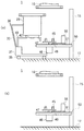
図5の符号101は従来技術の真空処理装置を示している。この真空処理装置101は搬出入室110と、処理室130とを有している。
処理室130は搬出入室110上の位置で搬出入室110に気密に接続されており、搬出入室110内部に配置された基板を外気に晒さずに処理室130内部に搬出入可能になっている。
The
搬出入室110の内部には複数枚の基板を配置可能になっており、処理室130内部でエッチング処理された基板は、処理室130から搬出入室110に戻され、エッチング処理される前の基板が新たに処理室130内部に搬入される。
A plurality of substrates can be arranged inside the carry-in / out
エッチング処理を複数回繰り返すと、処理室130の内部がプロセスガスによって汚染されるので、設定された回数エッチング処理を行った後、エッチング処理を中断し、処理室130を搬出入室110から取り外し、新たな処理室130を搬出入室110に取り付け、エッチング処理を再開する。
If the etching process is repeated a plurality of times, the inside of the
処理室130外壁に取り付けられた部品を取り外し、処理室130を搬出入室110から分離させる作業は人間が手作業で行っている。処理室130は搬出入室110の上に配置されているため、人間が脚立等を使用して取り外し作業を行っているが、処理室130の重量は非常に重いため、高い位置にある処理室130の取り外し作業は危険であった。
特に、近年基板サイズの大型化に伴い、処理室130も大型化しており、処理室130の交換作業は非常に危険な作業となっている。
In particular, with the recent increase in substrate size, the
本発明は上記従来技術の不都合を解決するために創作されたものであり、その目的は、処理室の交換作業が容易な真空処理装置を提供することである。 The present invention was created to solve the above-described disadvantages of the prior art, and an object of the present invention is to provide a vacuum processing apparatus in which the processing chamber can be easily replaced.
上記課題を解決するために、本発明は真空処理装置であって、基板を真空雰囲気中で処理する処理室と、前記処理室の上の位置で前記処理室に接続され、外部雰囲気から基板を搬入するように構成された搬出入室とを有し、前記基板は前記搬出入室と前記処理室との間を搬送されるように構成され、前記処理室と前記搬出入室の上下の位置関係を維持したまま、前記処理室を前記搬出入室から取り外しできるように構成された真空処理装置である。
本発明は真空処理装置であって、前記基板は前記外部雰囲気に晒されずに、前記搬出入室と前記処理室との間を搬送されるように構成された真空処理装置である。
本発明は真空処理装置であって、前記処理室に接続され、前記搬出入室から取り外された前記処理室を運搬する運搬手段を有し、前記運搬手段は、前記処理室が前記搬出入室に接続された状態でも、前記処理室に接続された真空処理装置である。
本発明は真空処理装置であって、前記搬出入室に前記処理室が接続された状態では、前記処理室にはガス供給系が接続され、ラジカルと、前記ガス供給系のプロセスガスを前記処理室内部に供給すると、前記プロセスガスと、前記基板表面の処理対象物とが反応し、前記処理対象物が前記基板表面から除去されるように構成された真空処理装置である。
本発明は上記のように構成されており、本発明の真空処理装置は、基板を搬出入室から処理室へ搬送、又は処理室から搬出入室へ搬送可能になっている。
基板の搬送は、処理室と搬出入室とを外部雰囲気に接続し、基板を大気に晒した状態で行ってもよいが、処理室と搬出入室を外部雰囲気から遮断し、基板を大気に晒さずに行えば、基板に大気中の水分や酸素によって汚染されることがない。In order to solve the above problems, the present invention is a vacuum processing apparatus, wherein a processing chamber for processing a substrate in a vacuum atmosphere is connected to the processing chamber at a position above the processing chamber, and the substrate is removed from an external atmosphere. A loading / unloading chamber configured to carry in, the substrate being configured to be transported between the loading / unloading chamber and the processing chamber, and maintaining a vertical positional relationship between the processing chamber and the loading / unloading chamber. The vacuum processing apparatus is configured such that the processing chamber can be detached from the carry-in / out chamber without being changed.
The present invention is a vacuum processing apparatus, wherein the substrate is transported between the carry-in / out chamber and the processing chamber without being exposed to the external atmosphere.
The present invention is a vacuum processing apparatus, comprising transport means for transporting the process chamber connected to the process chamber and removed from the carry-in / out chamber, wherein the transport means is connected to the carry-in / out chamber. Even in such a state, the vacuum processing apparatus is connected to the processing chamber.
The present invention is a vacuum processing apparatus, and in a state where the processing chamber is connected to the carry-in / out chamber, a gas supply system is connected to the processing chamber, and radicals and a process gas of the gas supply system are supplied to the processing chamber. The vacuum processing apparatus is configured such that when supplied to the inside, the process gas reacts with a processing target on the substrate surface, and the processing target is removed from the substrate surface.
The present invention is configured as described above, and the vacuum processing apparatus of the present invention can transfer the substrate from the loading / unloading chamber to the processing chamber or from the processing chamber to the loading / unloading chamber.
The substrate may be transferred with the processing chamber and the loading / unloading chamber connected to the external atmosphere and the substrate exposed to the atmosphere. However, the processing chamber and the loading / unloading chamber are shielded from the external atmosphere and the substrate is not exposed to the atmosphere. In this case, the substrate is not contaminated by moisture or oxygen in the atmosphere.
本発明では処理室は搬出入室の真下位置に配置されているので、重い処理室の取り外しが容易であり、取り外し作業が安全になる。また、処理室と搬出入室はその上下関係を維持したまま分離されるので、取り外し作業に広いスペースが必要なく、その取り外し工程も簡易で、従来に比べて作業時間が1/2程度に短縮される。処理室には運搬手段が接続されており、処理室が下降すると運搬手段も一緒に下降し、処理室が分離された状態では運搬手段が床面に接触した状態になり、運搬手段によって処理室を容易に運搬することができる。 In the present invention, since the processing chamber is disposed immediately below the loading / unloading chamber, it is easy to remove the heavy processing chamber, and the removal operation becomes safe. In addition, since the processing chamber and the loading / unloading chamber are separated while maintaining the vertical relationship, there is no need for a large space for the removal work, the removal process is simple, and the work time is reduced to about 1/2 compared to the conventional case. The The transport means is connected to the processing chamber. When the processing chamber is lowered, the transport means is also lowered. When the processing chamber is separated, the transport means is in contact with the floor surface. Can be easily transported.
1 真空処理装置
10 搬出入室
20 処理室
30 運搬手段
50 昇降機構DESCRIPTION OF
図1の符号1は本発明の真空処理装置を示しており、この真空処理装置1は搬出入室10と、処理室20と、昇降機構50とを有している。搬出入室10は支持部材18によって作業室の床面17から高い位置に固定されている。
昇降機構50は支持板51を有している。床面17には棒状のフレームワーク15が立設されており、支持板51はその表面が略水平にされた状態でフレームワーク15に固定されている。処理室20は、後述するボール45に載せられ、支持板51によってフレームワーク15に固定されている。
The
処理室20と搬出入室10は開口部をそれぞれ有しており、搬出入室10の開口部は下側に向けられている。処理室20がフレームワーク15に固定された状態では、処理室20の開口部は上側に向けられており、処理室20の開口部と搬出入室10の開口部はOリングを挟み込んだ状態で密着し、位置出しピン19によって固定された後、搬出入室10内部と処理室20内部を真空排気されることで、開口部同士が密閉され、搬出入室10と処理室20とが気密に接続されている。
The
搬出入室10の開口部には仕切りバルブが設けられており、仕切りバルブを開けた状態では搬出入室10の内部空間は処理室20の内部空間に接続され、搬出入室10の内部と処理室20の内部で基板の搬出入が可能になっている。
A partition valve is provided at the opening of the carry-in / out
次に、この真空処理装置1を用いて基板を処理する工程について説明する。処理室20と搬出入室10には不図示の真空排気系がそれぞれ接続されており、真空排気によって処理室20と搬出入室10の内部に所定圧力の真空雰囲気を形成しておく。
Next, the process of processing a substrate using the
搬出入室10の内部には、予め複数枚の基板が収納された搬送ボードが配置されており、仕切りバルブを開けて、搬送ボードを下降させ、搬出入室10から処理室20に移すと、搬送ボードの上端部である蓋部が処理室20の開口部に嵌り、処理室20の内部空間が搬出入室10の内部空間から遮断される。
Inside the carry-in / out
処理室20の外壁にはラジカル(H+)を生成する細長のアプリケーター29が略水平に向けた状態で取り付けられており、アプリケーター29で生成されたラジカルは処理室20内部に供給されるようになっている。An
処理室20にはプロセスガス供給系が接続されており、真空排気を続けながら、処理室20内にプロセスガス供給系のプロセスガス(例えば、NF3ガス)とアプリケーター29のラジカルを供給すると、基板上の自然酸化膜(ここでは酸化ケイ素膜)がプロセスガス及びラジカルと反応して反応生成物(ここではNH4SiF6)が生成される。A process gas supply system is connected to the
更に、ランプヒーターで基板を加熱すると、反応生成物が分解し、気体となって基板表面から除去された後、真空排気によって処理室20内部から排出される(エッチング工程)。
Further, when the substrate is heated with a lamp heater, the reaction product is decomposed and removed from the surface of the substrate as a gas, and then discharged from the inside of the
エッチング処理後、搬送ボードを上昇させて基板を搬出入室10に戻し、未処理の基板が収納された搬送ボードを処理室20内部へ下降させて基板の交換を行う。上述したエッチング工程と、基板の交換を繰り返し行えば、複数枚の基板を連続してエッチング処理することができる。
After the etching process, the transfer board is raised to return the substrate to the carry-in / out
繰り返しエッチング処理を行うと、処理室20内部が次第にプロセスガスで汚染されるので、処理室20を交換する必要がある。
処理室20を交換する工程について説明すると、予め設定された枚数の基板のエッチング処理が終了し、処理済みの基板を搬出入室10へ戻した後、仕切りバルブを閉め、真空排気によって、エッチングプロセスに使われたガスを完全に除去するために、処理室20内部の圧力を所定圧力に下げる。When the etching process is repeatedly performed, the inside of the
The process of exchanging the
昇降機構50はシリンダー46と支持軸47とボール45とを有している。シリンダー46は支持板51よりも下方位置で支持板51に取り付けられており、支持軸47の下端はシリンダー46に接続され、上端は支持板51よりも上方に突き出されている。
The
支持軸47の上端には取り付け板49が取り付けられ、ボール45はその取り付け板49上に配置されており、処理室20が搬出入室10に接続された状態ではボール45は処理室20の底壁に押し当てられ、処理室20を支持している。従って、処理室20が搬出入室10に接続された状態では、処理室20はボール45に載せられた状態で支持板51によってフレームワーク15に固定されている。
A mounting
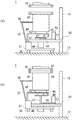
支持板51上には水平移動可能な落下防止用のブロック55が配置されており、処理室20が搬出入室10に接続された状態では、ブロック55は取り付け板49の下方位置に配置されている。処理室20を交換するためには、まず、このブロック55を支持板51上で水平方向に移動させ、取り付け板49の下方位置から退避させる(図2(a))。
On the
処理室20に基板を加熱する加熱手段が取り付けられている場合は該加熱手段への通電を停止し、処理室20を冷却する冷却装置が取り付けられている場合は該冷却装置を停止し、冷却装置や加熱手段に電力を供給する配線用コネクタを外す。
When a heating means for heating the substrate is attached to the
処理室20には、真空排気系の配管と、プロセスガス供給系の配管と、アプリケーター29の配管を、処理室20に接続するパイプが設けられており、パイプに設けられた仕切りバルブを閉じ、真空排気系とプロセスガス供給系とアプリケーター29を処理室20から遮断した状態で、処理室20内部にN2ガスを導入して、処理室20の内部雰囲気を大気圧に復圧した後、各配管を取り外す。The
処理室20の開口部は搬出入室10の開口部に密着しているが、処理室20内部を復圧した状態で、位置出しピン19を外し、シリンダー46を動作させ、支持軸47を下降させると、ボール45と一緒に処理室20が下降する。このとき、搬出入室10は支持部材18によって固定されているので、搬出入室10は処理室20の上方に残り、処理室20が搬出入室10から分離される。
Although the opening of the
この真空処理装置1は運搬手段30を有している。運搬手段30は板状の台座31を有しており、台座31はその表面が処理室20に向けられ、裏面が床面17に向けられている。台座31の表面には棒状の持ち手33が立設されており、持ち手33の上端は折り曲げられ、処理室20の側壁に固定されている。従って、この運搬手段30は処理室20に固定されており、処理室20が下降すると運搬手段30も一緒に下降する。
The
台座31の裏面には車輪35が取り付けられており、処理室20が下降する前は車輪35は床面17に接触しておらず、車輪35が浮いた状態になっているが、処理室20と一緒に運搬手段30が下降すると、車輪35が床面17に接触する。
A
台座31表面には保持プレート40が取り付け板49よりも上方位置で固定されており、保持プレート40にはボール45よりも大径な開口42が設けられている。
A holding
車輪35が床面17に接触すると、台座31と保持プレート40はそれ以上下降しないが、ボール45は開口42を通って保持プレート40よりも下方位置まで下降するので、処理室20の荷重はボール45から保持プレート40に移り、処理室20は運搬手段30で支えられた状態になる(図2(b))。
When the
処理室20が保持プレート40に移載された後、持ち手33を引っ張ると車輪35が回転し、図3(a)に示すように、処理室20と、運搬手段30とは一緒に搬出入室10の真下位置から移動し、処理室20が搬出入室10から取り除かれる。
After the
図3(b)は処理室20が搬出入室10から取り除かれた状態を示しており、昇降機構50は処理室20から分離され、支持板51がフレームワーク15に固定された状態で搬出入室10の真下に残る。取り除かれた処理室20は、運搬手段30から取り外した後、別室にて内部洗浄等のメンテナンスが行われる。
FIG. 3B shows a state where the
次に、エッチング使用前、又は、保守作業後の処理室20を搬出入室10に接続する工程について説明すると、先ず処理室20を運搬手段30の保持プレート40上に載せ、その側壁に持ち手33を固定する。その状態では、昇降機構50は台座31に固定されており、持ち手33を押し、処理室20と昇降機構50と一緒に運搬手段30を搬出入室10の下方位置まで移動させる(図4(a))。
Next, a process of connecting the
処理室20の開口部が搬出入室10の開口部の真下に位置させ、その状態でシリンダー46を動作させ、ボール45を保持プレート40よりも高い位置まで上昇させると、処理室20がボール45に移載される。
When the opening of the
更に、ボール45を上昇させると、処理室20が運搬手段30と一緒に上昇し、処理室20の開口部が搬出入室10の開口部に接触し、運搬手段30の車輪35が床面17から浮いた状態になる(図4(b))。
When the
処理室20を支持するボール45は回転可能になっているので、処理室20を押すと、ボール45の回転によって処理室20を水平方向に若干移動させることが可能なっている。
Since the
搬出入室10の開口部と、処理室20の開口部には位置出しピン19を取り付けるための孔27、28がそれぞれ設けられており、手動で処理室20を押し、搬出入室10の孔27と処理室20の孔28とが連通するように処理室20を移動させる。
このとき、運搬手段30の車輪35は床面17から浮いた状態になっているので、孔27、28が連通した後、車輪35によって処理室20が移動せず、孔27、28の位置ずれが起こらない。
連通した孔27、28に位置出しピン19を通し、処理室20の開口部が搬出入室10の開口部に接触し、固定される。At this time, since the
The
次いで、処理室20にアプリケーター29を取り付け、真空排気系やプロセスガス供給系の配管を処理室20に接続し、冷却装置や加熱手段に電力を供給する配線用コネクタを外部電源のコネクタに接続する。
Next, an
次いで、真空排気系によって処理室20の内部を真空排気すると、上述したように、処理室20と搬出入室10とが気密に接続される。処理室20内部に所定圧力の真空雰囲気が形成されたところで、ブロック55を支持板51上で移動させ、取り付け板49の下方位置に配置させると、図1に示したように処理室20は支持板51を介してフレームワーク15に固定された状態になり、仕切りバルブを開けて搬出入室10から新たな基板を搬入すれば、エッチング処理等の処理工程を再び開始することができる。
Next, when the inside of the
本発明の真空処理装置1では、処理室20が搬出入室10よりも下方にあるため、基板処理中や基板搬送中に発生するパーティクルが処理室20の底壁にたまりやすいという問題があるが、処理室20内部を真空排気する排気管とは別に、処理室20の底壁部に排気管を設け、該排気管からも処理室20内部を真空排気しながら基板の処理を行えば、パーティクルを処理室20外部に排出することができる。
In the
搬送ボードが下降するときには、例えば、その蓋部と処理室20の開口部とでOリングを挟み込むことで、処理室20の内部空間が搬出入室10の内部空間から遮断される。
搬送ボードには不図示の回転軸を設け、回転軸を回転させ、基板を水平面内で回転させながらエッチング工程を行えば、プロセスガスが基板表面に均一に行き渡るのでエッチング効率が高くなる。When the transfer board is lowered, for example, the internal space of the
If the transfer board is provided with a rotation shaft (not shown), the rotation shaft is rotated, and the etching process is performed while rotating the substrate in a horizontal plane, the process gas uniformly reaches the substrate surface, so that the etching efficiency increases.
また、回転軸と、搬送ボードの蓋部との隙間を密閉するのには磁性流体シールが用いられる。従来のようにゴム製の密閉部材(例えばOリング)を使用していないので、基板処理中に搬送ボードを回転させた場合であっても、密閉部材との擦れによるパーティクルが発生しない。従って、本発明の真空処理装置1では処理室20内部にパーティクルが溜まり難い。
Further, a magnetic fluid seal is used to seal a gap between the rotating shaft and the cover board lid. Since a rubber sealing member (for example, an O-ring) is not used as in the prior art, particles due to rubbing with the sealing member are not generated even when the transport board is rotated during substrate processing. Therefore, in the
以上は、処理室20でエッチング処理を行う場合について説明したが、処理室20で行われる処理は真空雰囲気で基板を処理するものであれば特に限定されるものではなく、例えば熱拡散法、熱CVD法、スパッタリング、蒸着等により基板表面に膜を形成することもできる。
ブロック55やボール45を構成する材料は特に限定されるものではないが、例えばSUS(ステンレス鋼)等を用いることができる。Although the case where the etching process is performed in the
Although the material which comprises the
また、運搬手段30は処理室20と一緒に搬出入室10に接続する必要はなく、例えば、処理室20を昇降機構50のボール45に移載した後、運搬手段30を処理室20から取り外してもよい。この場合は、処理室20を搬出入室10から分離する前に、処理室20下方に運搬手段を配置し、処理室20が下降した時に、処理室20を運搬手段に載置するようにしておき、処理室20が運搬手段に載置されてから、処理室20を運搬手段に固定すれば、運搬手段によって処理室20を運搬することができる。
Further, the transport means 30 does not need to be connected to the carry-in / out
Claims (4)
前記処理室の上の位置で前記処理室に接続され、外部雰囲気から基板を搬入するように構成された搬出入室とを有し、
前記基板は前記搬出入室と前記処理室との間を搬送されるように構成され、
前記処理室と前記搬出入室の上下の位置関係を維持したまま、前記処理室を前記搬出入室から取り外しできるように構成された真空処理装置。A processing chamber for processing the substrate in a vacuum atmosphere;
A loading / unloading chamber connected to the processing chamber at a position above the processing chamber and configured to load a substrate from an external atmosphere;
The substrate is configured to be transferred between the carry-in / out chamber and the processing chamber,
A vacuum processing apparatus configured to be able to remove the processing chamber from the loading / unloading chamber while maintaining a vertical positional relationship between the processing chamber and the loading / unloading chamber.
前記運搬手段は、前記処理室が前記搬出入室に接続された状態でも、前記処理室に接続された請求項1記載の真空処理装置。A transporting means for transporting the processing chamber connected to the processing chamber and removed from the loading / unloading chamber;
The vacuum processing apparatus according to claim 1, wherein the transport means is connected to the processing chamber even when the processing chamber is connected to the carry-in / out chamber.
ラジカルと、前記ガス供給系のプロセスガスを前記処理室内部に供給すると、前記プロセスガスと、前記基板表面の処理対象物とが反応し、前記処理対象物が前記基板表面から除去されるように構成された請求項1記載の真空処理装置。In a state where the processing chamber is connected to the carry-in / out chamber, a gas supply system is connected to the processing chamber,
When the radical and the process gas of the gas supply system are supplied to the inside of the processing chamber, the process gas reacts with the processing target on the substrate surface so that the processing target is removed from the substrate surface. The vacuum processing apparatus according to claim 1 configured.
Applications Claiming Priority (3)
| Application Number | Priority Date | Filing Date | Title |
|---|---|---|---|
| JP2004193569 | 2004-06-30 | ||
| JP2004193569 | 2004-06-30 | ||
| PCT/JP2005/011808 WO2006003880A1 (en) | 2004-06-30 | 2005-06-28 | Vacuum treatment device |
Publications (2)
| Publication Number | Publication Date |
|---|---|
| JPWO2006003880A1 JPWO2006003880A1 (en) | 2008-04-17 |
| JP4673308B2 true JP4673308B2 (en) | 2011-04-20 |
Family
ID=35782687
Family Applications (1)
| Application Number | Title | Priority Date | Filing Date |
|---|---|---|---|
| JP2006528695A Active JP4673308B2 (en) | 2004-06-30 | 2005-06-28 | Vacuum processing equipment |
Country Status (7)
| Country | Link |
|---|---|
| US (1) | US7682481B2 (en) |
| JP (1) | JP4673308B2 (en) |
| KR (1) | KR100808820B1 (en) |
| CN (1) | CN100492599C (en) |
| DE (1) | DE112005001539B4 (en) |
| TW (1) | TW200607013A (en) |
| WO (1) | WO2006003880A1 (en) |
Families Citing this family (2)
| Publication number | Priority date | Publication date | Assignee | Title |
|---|---|---|---|---|
| KR100841741B1 (en) * | 2007-04-04 | 2008-06-27 | 주식회사 싸이맥스 | Vacuum treating apparatus |
| CN114481098A (en) * | 2022-01-17 | 2022-05-13 | 成都四威高科技产业园有限公司 | Cavity PECVD equipment transmission with safeguard function |
Citations (7)
| Publication number | Priority date | Publication date | Assignee | Title |
|---|---|---|---|---|
| JPH08111449A (en) * | 1994-08-19 | 1996-04-30 | Tokyo Electron Ltd | Processing system |
| JP2000182967A (en) * | 1998-12-15 | 2000-06-30 | Sony Corp | Method and device for vapor-phase growth |
| JP2000273631A (en) * | 1999-03-24 | 2000-10-03 | Olympus Optical Co Ltd | Sputtering device |
| JP2001035842A (en) * | 1999-07-19 | 2001-02-09 | Sony Corp | Cvd device and manufacture of semiconductor device |
| JP2002028469A (en) * | 2000-07-12 | 2002-01-29 | Ulvac Japan Ltd | Vacuum equipment |
| JP2002280438A (en) * | 2001-03-19 | 2002-09-27 | Ulvac Japan Ltd | Vacuum treatment method |
| JP2003229417A (en) * | 2001-11-28 | 2003-08-15 | Tokyo Electron Ltd | Vacuum processing apparatus and method of controlling the same |
Family Cites Families (3)
| Publication number | Priority date | Publication date | Assignee | Title |
|---|---|---|---|---|
| DE3735284A1 (en) * | 1987-10-17 | 1989-04-27 | Leybold Ag | DEVICE ACCORDING TO THE CAROUSEL PRINCIPLE FOR COATING SUBSTRATES |
| JPH01257193A (en) * | 1988-04-08 | 1989-10-13 | Sumitomo Electric Ind Ltd | Vapor-phase growth device for semiconductor |
| JPH06267808A (en) * | 1993-03-15 | 1994-09-22 | Hitachi Ltd | Multiple-chamber apparatus having guide mechanism for connecting chamber |
-
2005
- 2005-06-28 WO PCT/JP2005/011808 patent/WO2006003880A1/en active Application Filing
- 2005-06-28 DE DE112005001539T patent/DE112005001539B4/en not_active Expired - Fee Related
- 2005-06-28 KR KR1020067027765A patent/KR100808820B1/en active IP Right Grant
- 2005-06-28 CN CNB2005800219785A patent/CN100492599C/en active Active
- 2005-06-28 JP JP2006528695A patent/JP4673308B2/en active Active
- 2005-06-29 TW TW094121933A patent/TW200607013A/en unknown
-
2006
- 2006-12-28 US US11/646,593 patent/US7682481B2/en active Active
Patent Citations (7)
| Publication number | Priority date | Publication date | Assignee | Title |
|---|---|---|---|---|
| JPH08111449A (en) * | 1994-08-19 | 1996-04-30 | Tokyo Electron Ltd | Processing system |
| JP2000182967A (en) * | 1998-12-15 | 2000-06-30 | Sony Corp | Method and device for vapor-phase growth |
| JP2000273631A (en) * | 1999-03-24 | 2000-10-03 | Olympus Optical Co Ltd | Sputtering device |
| JP2001035842A (en) * | 1999-07-19 | 2001-02-09 | Sony Corp | Cvd device and manufacture of semiconductor device |
| JP2002028469A (en) * | 2000-07-12 | 2002-01-29 | Ulvac Japan Ltd | Vacuum equipment |
| JP2002280438A (en) * | 2001-03-19 | 2002-09-27 | Ulvac Japan Ltd | Vacuum treatment method |
| JP2003229417A (en) * | 2001-11-28 | 2003-08-15 | Tokyo Electron Ltd | Vacuum processing apparatus and method of controlling the same |
Also Published As
| Publication number | Publication date |
|---|---|
| WO2006003880A1 (en) | 2006-01-12 |
| DE112005001539B4 (en) | 2013-04-25 |
| US20070151669A1 (en) | 2007-07-05 |
| CN100492599C (en) | 2009-05-27 |
| KR100808820B1 (en) | 2008-03-03 |
| DE112005001539T5 (en) | 2007-05-16 |
| TWI380356B (en) | 2012-12-21 |
| US7682481B2 (en) | 2010-03-23 |
| JPWO2006003880A1 (en) | 2008-04-17 |
| TW200607013A (en) | 2006-02-16 |
| CN1977363A (en) | 2007-06-06 |
| KR20070032968A (en) | 2007-03-23 |
Similar Documents
| Publication | Publication Date | Title |
|---|---|---|
| US4908095A (en) | Etching device, and etching method | |
| JP4916140B2 (en) | Vacuum processing system | |
| JP2003077974A (en) | Substrate processing device and manufacturing method of semiconductor device | |
| JP2009062604A (en) | Vacuum treatment system, and method for carrying substrate | |
| TWI767918B (en) | Plasma etching method, plasma etching apparatus, and substrate stage | |
| TWI484555B (en) | Substrate processing apparatus and semiconductor devices manufacturing method | |
| JP2008053550A (en) | Substrate processing apparatus and method, and storage medium | |
| EP0416646B1 (en) | Apparatus and method for processing substrates | |
| CN107790355B (en) | Reduced-pressure drying device, reduced-pressure drying system, and reduced-pressure drying method | |
| JP4673308B2 (en) | Vacuum processing equipment | |
| KR20020091765A (en) | Substrate processing apparatus and a method for fabricating a semiconductor device by using same | |
| KR101399904B1 (en) | Apparatus for cleaning substrate with plasma | |
| TW200929352A (en) | Vacuum processing apparatus | |
| JP2741156B2 (en) | Cleaning method for multi-chamber processing equipment | |
| JP2003059998A (en) | Tray-type multi-chamber substrate treating system and tray-type substrate treating system | |
| KR101092510B1 (en) | Vacuum processing device | |
| JP2018078197A (en) | Plasma processing apparatus and plasma processing method | |
| JP3066691B2 (en) | Multi-chamber processing apparatus and cleaning method thereof | |
| KR20130016359A (en) | Substrate processing method and substrate processing system | |
| JP2005347667A (en) | Semiconductor fabrication device | |
| JP4270413B2 (en) | Process equipment | |
| JP2008024975A (en) | Semi-conductor manufacturing equipment | |
| JP2948290B2 (en) | Substrate processing equipment | |
| KR100489638B1 (en) | Dry etching equipment of semiconductor device manufacturing equipment | |
| JP2005175068A (en) | Substrate-processing apparatus |
Legal Events
| Date | Code | Title | Description |
|---|---|---|---|
| A621 | Written request for application examination |
Free format text: JAPANESE INTERMEDIATE CODE: A621 Effective date: 20080509 |
|
| TRDD | Decision of grant or rejection written | ||
| A01 | Written decision to grant a patent or to grant a registration (utility model) |
Free format text: JAPANESE INTERMEDIATE CODE: A01 Effective date: 20110118 |
|
| A01 | Written decision to grant a patent or to grant a registration (utility model) |
Free format text: JAPANESE INTERMEDIATE CODE: A01 |
|
| A61 | First payment of annual fees (during grant procedure) |
Free format text: JAPANESE INTERMEDIATE CODE: A61 Effective date: 20110120 |
|
| R150 | Certificate of patent or registration of utility model |
Free format text: JAPANESE INTERMEDIATE CODE: R150 Ref document number: 4673308 Country of ref document: JP Free format text: JAPANESE INTERMEDIATE CODE: R150 |
|
| FPAY | Renewal fee payment (event date is renewal date of database) |
Free format text: PAYMENT UNTIL: 20140128 Year of fee payment: 3 |
|
| R250 | Receipt of annual fees |
Free format text: JAPANESE INTERMEDIATE CODE: R250 |
|
| R250 | Receipt of annual fees |
Free format text: JAPANESE INTERMEDIATE CODE: R250 |
|
| R250 | Receipt of annual fees |
Free format text: JAPANESE INTERMEDIATE CODE: R250 |
|
| R250 | Receipt of annual fees |
Free format text: JAPANESE INTERMEDIATE CODE: R250 |
|
| R250 | Receipt of annual fees |
Free format text: JAPANESE INTERMEDIATE CODE: R250 |
|
| R250 | Receipt of annual fees |
Free format text: JAPANESE INTERMEDIATE CODE: R250 |
|
| R250 | Receipt of annual fees |
Free format text: JAPANESE INTERMEDIATE CODE: R250 |
|
| R250 | Receipt of annual fees |
Free format text: JAPANESE INTERMEDIATE CODE: R250 |
|
| R250 | Receipt of annual fees |
Free format text: JAPANESE INTERMEDIATE CODE: R250 |