JP2009062604A - Vacuum treatment system, and method for carrying substrate - Google Patents
Vacuum treatment system, and method for carrying substrate Download PDFInfo
- Publication number
- JP2009062604A JP2009062604A JP2007233724A JP2007233724A JP2009062604A JP 2009062604 A JP2009062604 A JP 2009062604A JP 2007233724 A JP2007233724 A JP 2007233724A JP 2007233724 A JP2007233724 A JP 2007233724A JP 2009062604 A JP2009062604 A JP 2009062604A
- Authority
- JP
- Japan
- Prior art keywords
- chamber
- processing
- transfer
- pressure
- substrate
- Prior art date
- Legal status (The legal status is an assumption and is not a legal conclusion. Google has not performed a legal analysis and makes no representation as to the accuracy of the status listed.)
- Ceased
Links
Images


Classifications
-
- H—ELECTRICITY
- H01—ELECTRIC ELEMENTS
- H01L—SEMICONDUCTOR DEVICES NOT COVERED BY CLASS H10
- H01L21/00—Processes or apparatus adapted for the manufacture or treatment of semiconductor or solid state devices or of parts thereof
- H01L21/67—Apparatus specially adapted for handling semiconductor or electric solid state devices during manufacture or treatment thereof; Apparatus specially adapted for handling wafers during manufacture or treatment of semiconductor or electric solid state devices or components ; Apparatus not specifically provided for elsewhere
- H01L21/67005—Apparatus not specifically provided for elsewhere
- H01L21/67011—Apparatus for manufacture or treatment
- H01L21/67155—Apparatus for manufacturing or treating in a plurality of work-stations
- H01L21/67184—Apparatus for manufacturing or treating in a plurality of work-stations characterized by the presence of more than one transfer chamber
-
- C—CHEMISTRY; METALLURGY
- C23—COATING METALLIC MATERIAL; COATING MATERIAL WITH METALLIC MATERIAL; CHEMICAL SURFACE TREATMENT; DIFFUSION TREATMENT OF METALLIC MATERIAL; COATING BY VACUUM EVAPORATION, BY SPUTTERING, BY ION IMPLANTATION OR BY CHEMICAL VAPOUR DEPOSITION, IN GENERAL; INHIBITING CORROSION OF METALLIC MATERIAL OR INCRUSTATION IN GENERAL
- C23C—COATING METALLIC MATERIAL; COATING MATERIAL WITH METALLIC MATERIAL; SURFACE TREATMENT OF METALLIC MATERIAL BY DIFFUSION INTO THE SURFACE, BY CHEMICAL CONVERSION OR SUBSTITUTION; COATING BY VACUUM EVAPORATION, BY SPUTTERING, BY ION IMPLANTATION OR BY CHEMICAL VAPOUR DEPOSITION, IN GENERAL
- C23C14/00—Coating by vacuum evaporation, by sputtering or by ion implantation of the coating forming material
- C23C14/22—Coating by vacuum evaporation, by sputtering or by ion implantation of the coating forming material characterised by the process of coating
- C23C14/56—Apparatus specially adapted for continuous coating; Arrangements for maintaining the vacuum, e.g. vacuum locks
- C23C14/564—Means for minimising impurities in the coating chamber such as dust, moisture, residual gases
- C23C14/566—Means for minimising impurities in the coating chamber such as dust, moisture, residual gases using a load-lock chamber
-
- C—CHEMISTRY; METALLURGY
- C23—COATING METALLIC MATERIAL; COATING MATERIAL WITH METALLIC MATERIAL; CHEMICAL SURFACE TREATMENT; DIFFUSION TREATMENT OF METALLIC MATERIAL; COATING BY VACUUM EVAPORATION, BY SPUTTERING, BY ION IMPLANTATION OR BY CHEMICAL VAPOUR DEPOSITION, IN GENERAL; INHIBITING CORROSION OF METALLIC MATERIAL OR INCRUSTATION IN GENERAL
- C23C—COATING METALLIC MATERIAL; COATING MATERIAL WITH METALLIC MATERIAL; SURFACE TREATMENT OF METALLIC MATERIAL BY DIFFUSION INTO THE SURFACE, BY CHEMICAL CONVERSION OR SUBSTITUTION; COATING BY VACUUM EVAPORATION, BY SPUTTERING, BY ION IMPLANTATION OR BY CHEMICAL VAPOUR DEPOSITION, IN GENERAL
- C23C16/00—Chemical coating by decomposition of gaseous compounds, without leaving reaction products of surface material in the coating, i.e. chemical vapour deposition [CVD] processes
- C23C16/44—Chemical coating by decomposition of gaseous compounds, without leaving reaction products of surface material in the coating, i.e. chemical vapour deposition [CVD] processes characterised by the method of coating
- C23C16/4401—Means for minimising impurities, e.g. dust, moisture or residual gas, in the reaction chamber
-
- C—CHEMISTRY; METALLURGY
- C23—COATING METALLIC MATERIAL; COATING MATERIAL WITH METALLIC MATERIAL; CHEMICAL SURFACE TREATMENT; DIFFUSION TREATMENT OF METALLIC MATERIAL; COATING BY VACUUM EVAPORATION, BY SPUTTERING, BY ION IMPLANTATION OR BY CHEMICAL VAPOUR DEPOSITION, IN GENERAL; INHIBITING CORROSION OF METALLIC MATERIAL OR INCRUSTATION IN GENERAL
- C23C—COATING METALLIC MATERIAL; COATING MATERIAL WITH METALLIC MATERIAL; SURFACE TREATMENT OF METALLIC MATERIAL BY DIFFUSION INTO THE SURFACE, BY CHEMICAL CONVERSION OR SUBSTITUTION; COATING BY VACUUM EVAPORATION, BY SPUTTERING, BY ION IMPLANTATION OR BY CHEMICAL VAPOUR DEPOSITION, IN GENERAL
- C23C16/00—Chemical coating by decomposition of gaseous compounds, without leaving reaction products of surface material in the coating, i.e. chemical vapour deposition [CVD] processes
- C23C16/44—Chemical coating by decomposition of gaseous compounds, without leaving reaction products of surface material in the coating, i.e. chemical vapour deposition [CVD] processes characterised by the method of coating
- C23C16/54—Apparatus specially adapted for continuous coating
-
- H—ELECTRICITY
- H01—ELECTRIC ELEMENTS
- H01L—SEMICONDUCTOR DEVICES NOT COVERED BY CLASS H10
- H01L21/00—Processes or apparatus adapted for the manufacture or treatment of semiconductor or solid state devices or of parts thereof
- H01L21/67—Apparatus specially adapted for handling semiconductor or electric solid state devices during manufacture or treatment thereof; Apparatus specially adapted for handling wafers during manufacture or treatment of semiconductor or electric solid state devices or components ; Apparatus not specifically provided for elsewhere
- H01L21/67005—Apparatus not specifically provided for elsewhere
- H01L21/67011—Apparatus for manufacture or treatment
- H01L21/67155—Apparatus for manufacturing or treating in a plurality of work-stations
- H01L21/67196—Apparatus for manufacturing or treating in a plurality of work-stations characterized by the construction of the transfer chamber
Abstract
Description
本発明は、真空に保持可能な搬送室に処理チャンバを配してなる真空処理システムおよび真空処理システムにおける基板搬送方法に関する。 The present invention relates to a vacuum processing system in which a processing chamber is arranged in a transfer chamber capable of maintaining a vacuum, and a substrate transfer method in the vacuum processing system.
半導体デバイスの製造工程においては、被処理基板である半導体ウエハ(以下、単にウエハと記す)に、コンタクト構造や配線構造を形成するために、複数の金属または金属化合物膜を成膜するプロセスが行われる。このような成膜処理は、真空に保持された処理チャンバ内で行われるが、最近では、処理の効率化の観点、および酸化やコンタミネーション等の汚染を抑制する観点から、複数の処理チャンバを真空に保持される搬送室に連結し、この搬送室に設けられた搬送装置により各処理チャンバにウエハを搬送可能としたクラスターツール型のマルチチャンバシステムが注目されている(例えば特許文献1)。このようなマルチチャンバシステムでは、ウエハを大気に曝すことなく連続して複数の膜を成膜することができるので、極めて効率的でかつ汚染の少ない処理を行うことができる。 In the manufacturing process of a semiconductor device, a process of forming a plurality of metal or metal compound films is performed in order to form a contact structure and a wiring structure on a semiconductor wafer (hereinafter simply referred to as a wafer) that is a substrate to be processed. Is called. Such film formation processing is performed in a processing chamber held in a vacuum, but recently, a plurality of processing chambers are provided from the viewpoint of improving the efficiency of processing and suppressing contamination such as oxidation and contamination. A cluster tool type multi-chamber system that is connected to a transfer chamber held in a vacuum and can transfer a wafer to each processing chamber by a transfer device provided in the transfer chamber has attracted attention (for example, Patent Document 1). In such a multi-chamber system, a plurality of films can be continuously formed without exposing the wafer to the atmosphere, so that it is possible to perform an extremely efficient process with little contamination.
ところで、近時、半導体デバイスの成膜処理は、スパッタリング等のPVD(Physical Vappor Deposition)により行われる場合と、CVD(Chemical Vappor Deposition)により行われる場合があり、その場合には、これらの処理を行う処理チャンバが同一のマルチチャンバシステムに搭載できれば、効率的な処理を行うことができる。しかしながら、これらは一般的に要求される真空度が異なり、PVDのほうが低圧で処理が行われる。また、一般的にCVDを行う際には汚染成分が発生する。このため、単純に同じ搬送室にCVD処理チャンバとPVD処理チャンバを配置する場合には、CVD処理チャンバの汚染成分がPVD処理チャンバに容易に拡散し、PVD処理チャンバで形成される膜の汚染や、PVD処理チャンバ自体の汚染が発生してしまう。 By the way, recently, film formation processing of a semiconductor device may be performed by PVD (Physical Vapor Deposition) such as sputtering, or by CVD (Chemical Vapor Deposition). In this case, these processes are performed. If the processing chambers to be performed can be mounted on the same multi-chamber system, efficient processing can be performed. However, these generally require different degrees of vacuum, and PVD is processed at a lower pressure. In general, contamination components are generated when CVD is performed. For this reason, when the CVD processing chamber and the PVD processing chamber are simply arranged in the same transfer chamber, contamination components of the CVD processing chamber easily diffuse into the PVD processing chamber, and contamination of the film formed in the PVD processing chamber Contamination of the PVD processing chamber itself will occur.
このようなことを防止する技術としては、搬送室にパージガスを流量制御しながら導入できるように構成し、処理対象物であるウエハを所定の処理チャンバに搬送する際に、搬送室の圧力をその処理チャンバの圧力よりも高くなるようにする技術が提案されている(特許文献2)。 As a technique for preventing this, the purge gas can be introduced into the transfer chamber while controlling the flow rate, and the pressure of the transfer chamber is set when the wafer as the processing object is transferred to a predetermined processing chamber. A technique for making the pressure higher than the pressure in the processing chamber has been proposed (Patent Document 2).
しかしながら、PVD処理とCVD処理とでは要求される圧力レベルが一般的に10000倍以上異なり、CVD処理チャンバに対するウエハの搬入出を行う場合には搬送室をさらに高い圧力にする必要があるため、特許文献2の技術では、圧力調整のために時間がかかり、スループットが低下するという問題がある。
本発明はかかる事情に鑑みてなされたものであって、要求される圧力レベルが相対的に高圧力レベルの処理チャンバと相対的に低圧力レベルの処理チャンバを有し、他の処理チャンバからの汚染をもたらさず、かつスループットを低下させずに各処理チャンバで処理を行うことができる真空処理システムおよび基板搬送方法を提供することを目的とする。 The present invention has been made in view of such circumstances, and has a processing chamber having a relatively high pressure level and a processing chamber having a relatively low pressure level required from other processing chambers. It is an object of the present invention to provide a vacuum processing system and a substrate transfer method capable of performing processing in each processing chamber without causing contamination and without reducing throughput.
上記課題を解決するため、本発明の第1の観点では、
相対的に低圧で被処理基板に対して真空処理を行う第1の処理チャンバと、前記第1の処理チャンバが接続され、被処理基板を前記第1の処理チャンバに対して搬入出する搬送機構を備え、その内部が前記第1の処理チャンバの処理圧力と適合した真空度に調整される第1の搬送室と、を有する第1の処理部と、
相対的に高圧で被処理体に対して真空処理を行う第2の処理チャンバと、前記第2の処理チャンバが接続され、被処理基板を前記第2の処理チャンバに対して搬入出する搬送機構を備え、その内部が前記第2の処理チャンバの処理圧力と適合した真空度に調整される第2の搬送室と、を有する第2の処理部と、
前記第1の搬送室および前記第2の搬送室の間にゲートバルブを介して設けられ、その内部に被処理基板が収容可能で、かつその内部が圧力調整可能なバッファ室と、
被処理基板を前記第1の搬送室および前記第2の搬送室のいずれか一方から他方へ搬送する際に、前記ゲートバルブを閉じた状態で、前記バッファ室の圧力を前記第1の搬送室および前記第2の搬送室のうち被処理基板が存在するほうの圧力に適合させ、当該被処理基板が存在する搬送室と前記バッファ室との間のゲートバルブを開放してこれらの間を選択的に連通させて、被処理基板を前記バッファ室へ搬入し、前記ゲートバルブを閉じて前記バッファ室を前記第1および第2の搬送室から遮断し、その状態で前記バッファ室の圧力を他方の搬送室の圧力に適合させ、前記バッファ室と前記他方の搬送室との間のゲートバルブを開放して被処理基板を前記バッファ室から他方の搬送室へ搬送するように制御する制御機構と
を具備する真空処理システム
を提供する。
In order to solve the above problem, in the first aspect of the present invention,
A first processing chamber that performs vacuum processing on a substrate to be processed at a relatively low pressure, and a transfer mechanism that connects the first processing chamber and carries the substrate into and out of the first processing chamber. A first transfer section having a first transfer chamber whose inside is adjusted to a degree of vacuum compatible with the processing pressure of the first processing chamber,
A second processing chamber that performs vacuum processing on the object to be processed at a relatively high pressure, and a transfer mechanism that connects the second processing chamber and carries the substrate to be processed in and out of the second processing chamber. And a second transfer chamber having an inside adjusted to a degree of vacuum adapted to the processing pressure of the second processing chamber,
A buffer chamber provided between the first transfer chamber and the second transfer chamber via a gate valve, in which a substrate to be processed can be accommodated, and the pressure inside thereof can be adjusted;
When the substrate to be processed is transferred from one of the first transfer chamber and the second transfer chamber to the other, the pressure in the buffer chamber is changed to the first transfer chamber with the gate valve closed. In addition, it is adapted to the pressure of the second transfer chamber where the substrate to be processed exists, and the gate valve between the transfer chamber where the substrate to be processed exists and the buffer chamber is opened to select between these The substrate is carried into the buffer chamber, the gate valve is closed, the buffer chamber is shut off from the first and second transfer chambers, and the pressure in the buffer chamber is changed to the other in this state. A control mechanism adapted to transfer the substrate to be processed from the buffer chamber to the other transfer chamber by adapting to the pressure of the transfer chamber and opening the gate valve between the buffer chamber and the other transfer chamber; Vacuum processing To provide a system.
上記第1の観点において、前記第1の処理チャンバとしてPVD処理を行うPVD処理チャンバを適用し、前記第2の処理チャンバとしてCVD処理を行うCVD処理チャンバを適用することができる。この場合に、前記第2の搬送室は、前記第2の処理チャンバよりも高圧に保持されることが好ましい。また、この場合に、前記第1の処理チャンバは1×10⁻⁷〜1×10⁻³Paの圧力に保持され、前記第2の処理チャンバは1×101〜1×10³Paの圧力に保持されるようにすることができる。 In the first aspect, a PVD processing chamber that performs PVD processing may be applied as the first processing chamber, and a CVD processing chamber that performs CVD processing may be applied as the second processing chamber. In this case, it is preferable that the second transfer chamber is held at a higher pressure than the second processing chamber. In this case, the first processing chamber is maintained at a pressure of 1 × 10 −7 to 1 × 10 −3 Pa, and the second processing chamber is maintained at a pressure of 1 × 10 1 to 1 × 10 3 Pa. It can be held in.
前記バッファ室は、その中を排気する排気機構と、その中にガスを導入するガス導入機構とを有し、前記排気機構と前記ガス導入機構により圧力調整可能である構成とすることができる。前記第1の搬送室は、その中を排気する排気機構を有し、この排気機構により前記第1の処理チャンバに適合した圧力にされる構成とすることができる。前記第2の搬送室は、その中を排気する排気機構と、その中にガスを導入するガス導入機構とを有し、これら排気機構とガス導入機構とにより前記処理チャンバに適合した圧力にされる構成とすることができる。 The buffer chamber may include an exhaust mechanism that exhausts the buffer chamber and a gas introduction mechanism that introduces gas into the buffer chamber, and the pressure can be adjusted by the exhaust mechanism and the gas introduction mechanism. The first transfer chamber may have an exhaust mechanism for exhausting the inside thereof, and the exhaust mechanism may be configured to have a pressure suitable for the first processing chamber. The second transfer chamber has an exhaust mechanism for exhausting the inside thereof and a gas introduction mechanism for introducing a gas therein, and the exhaust mechanism and the gas introduction mechanism are adjusted to a pressure suitable for the processing chamber. It can be set as a structure.
前記バッファ室は、前記第1の搬送室から前記第2の搬送室へ被処理基板を搬送する際に使用するものと、前記第2の搬送室から前記第1の搬送室へ被処理基板を搬送する際に使用するものの2つ設けられた構成とすることができる。 The buffer chamber is used when the substrate to be processed is transferred from the first transfer chamber to the second transfer chamber, and the substrate to be processed is transferred from the second transfer chamber to the first transfer chamber. It can be set as the structure provided with two of what is used when conveying.
本発明の第2の観点では、
相対的に低圧で被処理基板に対して真空処理を行う第1の処理チャンバと、前記第1の処理チャンバが接続され、被処理基板を前記第1の処理チャンバに対して搬入出する搬送機構を備え、その内部が前記第1の処理チャンバの処理圧力と適合した真空度に調整される第1の搬送室と、を有する第1の処理部と、
相対的に高圧で被処理体に対して真空処理を行う第2の処理チャンバと、前記第2の処理チャンバが接続され、被処理基板を前記第2の処理チャンバに対して搬入出する搬送機構を備え、その内部が前記第2の処理チャンバの処理圧力と適合した真空度に調整される第2の搬送室と、を有する第2の処理部と、
を具備する真空処理システムにおいて、被処理基板を前記第1の搬送室および前記第2の搬送室のいずれか一方から他方へ搬送する基板搬送方法であって、
前記第1の搬送室と前記第2の搬送室との間にゲートバルブを介して、その内部に被処理体を収容可能で、かつその内部が圧力調整可能なバッファ室を設け、
前記ゲートバルブを閉じた状態で、前記バッファ室の圧力を前記第1の搬送室および前記第2の搬送室のうち被処理基板が存在するほうの圧力に適合させ、当該被処理基板が存在する搬送室と前記バッファ室との間のゲートバルブを開放してこれらの間を選択的に連通させて、被処理基板を前記バッファ室へ搬入し、前記ゲートバルブを閉じて前記バッファ室を前記第1および第2の搬送室から遮断し、その状態で前記バッファ室の圧力を他方の搬送室の圧力に適合させ、前記バッファ室と前記他方の搬送室との間のゲートバルブを開放して被処理基板を前記バッファ室から他方の搬送室へ搬送することを特徴とする基板搬送方法
を提供する。
In a second aspect of the present invention,
A first processing chamber that performs vacuum processing on a substrate to be processed at a relatively low pressure, and a transfer mechanism that connects the first processing chamber and carries the substrate into and out of the first processing chamber. A first transfer section having a first transfer chamber whose inside is adjusted to a degree of vacuum compatible with the processing pressure of the first processing chamber,
A second processing chamber that performs vacuum processing on the object to be processed at a relatively high pressure, and a transfer mechanism that connects the second processing chamber and carries the substrate to be processed in and out of the second processing chamber. And a second transfer chamber having an inside adjusted to a degree of vacuum adapted to the processing pressure of the second processing chamber,
In the vacuum processing system comprising: a substrate transfer method for transferring a substrate to be processed from either one of the first transfer chamber and the second transfer chamber to the other,
A buffer chamber is provided between the first transfer chamber and the second transfer chamber via a gate valve, the object to be processed can be accommodated therein, and the pressure inside thereof can be adjusted,
With the gate valve closed, the pressure in the buffer chamber is adapted to the pressure of the first transfer chamber and the second transfer chamber where the substrate to be processed exists, and the substrate to be processed exists. A gate valve between the transfer chamber and the buffer chamber is opened to selectively communicate between them, the substrate to be processed is loaded into the buffer chamber, the gate valve is closed, and the buffer chamber is moved to the first chamber. Shut off from the first and second transfer chambers, and adjust the pressure in the buffer chamber to the pressure in the other transfer chamber in this state, and open the gate valve between the buffer chamber and the other transfer chamber. There is provided a substrate transfer method characterized in that a processing substrate is transferred from the buffer chamber to the other transfer chamber.
上記第2の観点において、前記第1の処理チャンバとしてPVD処理を行うPVD処理チャンバを適用し、前記第2の処理チャンバとしてCVD処理を行うCVD処理チャンバを適用することができる。 In the second aspect, a PVD processing chamber that performs PVD processing can be applied as the first processing chamber, and a CVD processing chamber that performs CVD processing can be applied as the second processing chamber.
本発明の第3の観点では、コンピュータ上で動作し、
相対的に低圧で被処理基板に対して真空処理を行う第1の処理チャンバと、前記第1の処理チャンバが接続され、被処理基板を前記第1の処理チャンバに対して搬入出する搬送機構を備え、その内部が前記第1の処理チャンバの処理圧力と適合した真空度に調整される第1の搬送室と、を有する第1の処理部と、
相対的に高圧で被処理体に対して真空処理を行う第2の処理チャンバと、前記第2の処理チャンバが接続され、被処理基板を前記第2の処理チャンバに対して搬入出する搬送機構を備え、その内部が前記第2の処理チャンバの処理圧力と適合した真空度に調整される第2の搬送室と、を有する第2の処理部と、
前記第1の搬送室と前記第2の搬送室との間にゲートバルブを介して、その内部に被処理体を収容可能で、かつその内部が圧力調整可能なバッファ室と
を具備する真空処理システムを制御するプログラムが記憶された記憶媒体であって、
前記プログラムは、実行時に、被処理基板を前記第1の搬送室および前記第2の搬送室のいずれか一方から他方へ搬送する基板搬送方法であって、前記ゲートバルブを閉じた状態で、前記バッファ室の圧力を前記第1の搬送室および前記第2の搬送室のうち被処理基板が存在するほうの圧力に適合させ、当該被処理基板が存在する搬送室と前記バッファ室との間のゲートバルブを開放してこれらの間を選択的に連通させて、被処理基板を前記バッファ室へ搬入し、前記ゲートバルブを閉じて前記バッファ室を前記第1および第2の搬送室から遮断し、その状態で前記バッファ室の圧力を他方の搬送室の圧力に適合させ、前記バッファ室と前記他方の搬送室との間のゲートバルブを開放して被処理基板を前記バッファ室から他方の搬送室へ搬送する基板搬送方法が行われるように、コンピュータに前記真空処理システムを制御させることを特徴とする記憶媒体
を提供する。
In a third aspect of the present invention, it operates on a computer,
A first processing chamber that performs vacuum processing on a substrate to be processed at a relatively low pressure, and a transfer mechanism that connects the first processing chamber and carries the substrate into and out of the first processing chamber. A first transfer section having a first transfer chamber whose inside is adjusted to a degree of vacuum compatible with the processing pressure of the first processing chamber,
A second processing chamber that performs vacuum processing on the object to be processed at a relatively high pressure, and a transfer mechanism that connects the second processing chamber and carries the substrate to be processed in and out of the second processing chamber. And a second transfer chamber having an inside adjusted to a degree of vacuum adapted to the processing pressure of the second processing chamber,
A vacuum process comprising a buffer chamber in which the object to be processed can be accommodated and the pressure inside thereof can be adjusted via a gate valve between the first transfer chamber and the second transfer chamber. A storage medium storing a program for controlling the system,
The program is a substrate transfer method for transferring a substrate to be processed from one of the first transfer chamber and the second transfer chamber to the other at the time of execution, with the gate valve closed, The pressure of the buffer chamber is adapted to the pressure of the first transfer chamber and the second transfer chamber where the substrate to be processed exists, and between the transfer chamber where the substrate to be processed exists and the buffer chamber. The gate valve is opened to selectively communicate between them, the substrate to be processed is carried into the buffer chamber, the gate valve is closed, and the buffer chamber is shut off from the first and second transfer chambers. In this state, the pressure in the buffer chamber is adapted to the pressure in the other transfer chamber, the gate valve between the buffer chamber and the other transfer chamber is opened, and the substrate to be processed is transferred from the buffer chamber to the other transfer chamber. Transport to room As substrate transfer method is performed that provides a storage medium, characterized in that to control the vacuum processing system to a computer.
本発明によれば、被処理基板を前記第1の搬送室および前記第2の搬送室のいずれか一方から他方へ搬送する際に、前記ゲートバルブを閉じた状態で、前記バッファ室の圧力を前記第1の搬送室および前記第2の搬送室のうち被処理基板が存在するほうの圧力に適合させ、当該被処理基板が存在する搬送室と前記バッファ室との間のゲートバルブを開放してこれらの間を選択的に連通させて、被処理基板を前記バッファ室へ搬入し、前記ゲートバルブを閉じて前記バッファ室を前記第1および第2の搬送室から遮断し、その状態で前記バッファ室の圧力を他方の搬送室の圧力に適合させ、前記バッファ室と前記他方の搬送室との間のゲートバルブを開放して被処理基板を前記バッファ室から他方の搬送室へ搬送するように制御するようにしたので、バッファ室によって、第1の搬送室と第2の搬送室21の雰囲気の遮断を行えるとともに、バッファ室の圧力を調整することにより、第1の搬送室と第2の搬送室の間の被処理基板の搬送が可能となる。このため、バッファ室の存在により、CVD処理チャンバのような相対的に高圧の第2の処理チャンバからPVD処理チャンバのような相対的に低圧の第1の処理チャンバへのクロスコンタミネーションを確実に防止することができるとともに、2つの搬送室の圧力を変動させる必要がなく、第1の搬送室と第2の搬送室との間でウエハWを搬送させる際のみ体積の小さいバッファ室の圧力を調整を行えばよいので、スループットを低下させずに真空処理を行うことができる。
According to the present invention, when the substrate to be processed is transported from one of the first transport chamber and the second transport chamber to the other, the pressure in the buffer chamber is set with the gate valve closed. The gate valve between the transfer chamber in which the substrate to be processed exists and the buffer chamber is opened by adapting to the pressure of the first transfer chamber and the second transfer chamber in which the substrate to be processed exists. Selectively communicating between them, the substrate to be processed is carried into the buffer chamber, the gate valve is closed, and the buffer chamber is shut off from the first and second transfer chambers, The pressure in the buffer chamber is adapted to the pressure in the other transfer chamber, the gate valve between the buffer chamber and the other transfer chamber is opened, and the substrate to be processed is transferred from the buffer chamber to the other transfer chamber. To control Thus, the buffer chamber can block the atmosphere of the first transfer chamber and the
以下、添付図面を参照して本発明の実施形態について具体的に説明する。
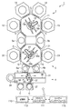
図1は本発明の一実施形態に係るマルチチャンバータイプの真空処理システムを示す平面図である。
Hereinafter, embodiments of the present invention will be specifically described with reference to the accompanying drawings.
FIG. 1 is a plan view showing a multi-chamber type vacuum processing system according to an embodiment of the present invention.
真空処理システム1は、高真空(低圧)での処理であるPVD処理、例えばスパッタリング処理を行う複数の処理チャンバを備えた第1の処理部2と、高圧での処理であるCVD処理を行う複数のチャンバを備えた第2の処理部3と、搬入出部4と、第1の処理部2と第2の処理部3とを接続する2つのバッファ室5a,5bとを有しており、ウエハWに対して所定の金属または金属化合物膜の成膜を実施することができるようになっている。
The
第1の処理部2は、平面形状が七角形をなす第1の搬送室11と、この第1の搬送室11の4つの辺に接続された4つのPVD処理チャンバ12,13,14、15とを有している。第1の搬送室11の他の2辺には、それぞれ上記バッファ室5a,5bが接続されている。PVD処理チャンバ12〜15およびバッファ室5a,5bは、第1の搬送室11の各辺にゲートバルブGを介して接続され、これらは対応するゲートバルブを開放することにより第1の搬送室11と連通され、対応するゲートバルブGを閉じることにより第1の搬送室11から遮断される。第1の搬送室11内には、PVD処理チャンバ12〜15、バッファ室5a,5bに対してウエハWの搬入出を行う第1の搬送機構16が設けられている。この第1の搬送機構16は、第1の搬送室11の略中央に配設されており、回転および伸縮可能な回転・伸縮部17の先端にウエハWを支持する2つの支持アーム18a,18bが設けられており、これら2つの支持アーム18a,18bは互いに反対方向を向くように回転・伸縮部17に取り付けられている。この第1の搬送室11内は後述するように所定の真空度に保持されるようになっている。
The first processing unit 2 includes a
第2の処理部3は、平面形状が七角形をなす第2の搬送室21と、この第2の搬送室21の対向する2つの辺に接続された2つのCVD処理チャンバ22,23とを有している。また、第2の搬送室21の第1の処理部2側の2辺には、それぞれ上記バッファ室5a,5bが接続されている。さらに、搬入出部4側の2辺には、それぞれロードロック室6a,6bが接続されている。処理チャンバ22,23、バッファ室5a,5b、およびロードロック室6a,6bは、第2の搬送室21の各辺にゲートバルブGを介して接続され、これらは対応するゲートバルブを開放することにより第2の搬送室21と連通され、対応するゲートバルブGを閉じることにより第2の搬送室21から遮断される。第2の搬送室21内には、CVD処理チャンバ22,23、バッファ室5a,5b、ロードロック室6a,6bに対してウエハWの搬入出を行う第2の搬送機構26が設けられている。この第2の搬送機構26は、第2の搬送室21の略中央に配設されており、回転および伸縮可能な回転・伸縮部27の先端にウエハWを支持する2つの支持アーム28a,28bが設けられており、これら2つの支持アーム28a,28bは互いに反対方向を向くように回転・伸縮部27に取り付けられている。この第2の搬送室21内は後述するように所定の真空度に保持されるようになっている。
The second processing unit 3 includes a
搬入出部4は、上記ロードロック室6a,6bを挟んで第2の処理部3と反対側に設けられており、ロードロック室6a,6bが接続される搬入出室31を有している。ロードロック室6a,6bと搬入出室31との間にはゲートバルブGが設けられている。搬入出室31のロードロック室6a,6bが接続された辺と対向する辺には被処理基板としてのウエハWを収容するキャリアCを接続する2つの接続ポート32,33が設けられている。これら接続ポート32,33にはそれぞれ図示しないシャッターが設けられており、これら接続ポート32,33にウエハWを収容した状態の、または空のキャリアCが直接取り付けられ、その際にシャッターが外れて外気の侵入を防止しつつ搬入出室31と連通するようになっている。また、搬入出室31の側面にはアライメントチャンバ34が設けられており、そこでウエハWのアライメントが行われる。搬入出室31内には、キャリアCに対するウエハWの搬入出およびロードロック室6a,6bに対する半導体ウエハWの搬入出を行う搬入出用搬送機構36が設けられている。この搬入出用搬送機構36は、2つの多関節アームを有しており、キャリアCの配列方向に沿ってレール38上を走行可能となっていて、それぞれの先端のハンド37上にウエハWを載せてその搬送を行うようになっている。
The loading /
次に、第1の処理部2および第2の処理部の構造について具体的に説明する。図2は、第1の処理部2および第2の処理部3を模式的に示す断面図である。 Next, the structures of the first processing unit 2 and the second processing unit will be specifically described. FIG. 2 is a cross-sectional view schematically showing the first processing unit 2 and the second processing unit 3.
第1の処理部2の第1の搬送室11は、上述したように高真空での処理を行う相対的に低圧力のPVD処理チャンバ12〜15のいずれかにウエハWを搬送する際に、そのPVD処理チャンバと連通されるため、第1の搬送室11内の圧力は、PVD処理チャンバ12〜15と同程度の高真空状態に保持される。具体的には、PVD処理チャンバは、通常、1×10⁻⁷〜1×10⁻³Pa(約1×10⁻⁹〜10×10−5Torr)程度の圧力に保持され、第1の搬送室11もこの程度の圧力に保持される。このような圧力を維持する観点から、第1の搬送室11には、その底部に排気口41が設けられており、この排気口41には排気配管42が接続されている。そして、排気配管42には、排気速度調整バルブ43および真空ポンプ44が介在されている。したがって、真空ポンプ44により真空排気しつつ排気速度調整バルブ43により排気を調整することにより、第1の搬送室11内の圧力を上記範囲に制御することができる。
When the
第2の処理部3の第2の搬送室21は、上述したように、相対的に高圧力での処理を行うCVD処理チャンバ22,23のいずれかにウエハWを搬送する際に、そのCVD処理チャンバと連通されるため、第2の搬送室21内の圧力は、CVD処理チャンバ22,23と同程度の圧力に保持される。具体的には、CVD処理チャンバは、通常、1×101〜1×103Pa(約1×10−1〜1×101Torr)程度に保持され、第2の搬送室21もこの程度の圧力に保持される。このような圧力を維持する観点から、第2の搬送室22には、その底部に排気口51が設けられており、その天壁にはガス導入口55が設けられている。排気口51には排気配管52が接続されている。そして、排気配管52には、排気速度調整バルブ53および真空ポンプ54が介在されている。また、ガス導入口55にはパージガスを導入するためのガス導入配管56が接続され、ガス導入配管56には流量調節バルブ57が設けられている。したがって、真空ポンプ54により真空排気しつつ排気速度調整バルブ53により排気を調整し、かつガス導入配管56から所定流量でパージガス(例えばArガス)を第2の搬送室21に導入することにより、第2の搬送室21内の圧力を上記範囲に制御することができる。なお、CVD成膜処理は、汚染物質を多量に発生させるため、CVD処理チャンバ間のクロスコンタミネーションを防止する観点からは、第2の搬送室21はCVD処理チャンバ22,23よりも高圧に保持し、第2搬送室21からCVD処理チャンバ22,23へのガス流を形成することが好ましい。
As described above, the
バッファ室5a(5b)は、上述したように第1の搬送室11および第2の搬送室21の間にゲートバルブGを介して設けられ、いずれかのゲートバルブGを開放することにより第1の搬送室11および第2の搬送室21の一方に連通されるようになっており、その内部にウエハWが収容可能に、かつその内部が圧力調整可能に構成されている。具体的には、その底部に排気口61が設けられており、その天壁にはガス導入口65が設けられている。排気口61には排気配管62が接続されている。そして、排気配管62には、排気速度調整バルブ63および真空ポンプ64が介在されている。また、ガス導入口65にはパージガスを導入するためのガス導入配管66が接続され、ガス導入配管66には流量調節バルブ67が設けられている。したがって、真空ポンプ64により真空排気しつつ排気速度調整バルブ63によって排気を調整することにより、バッファ室5a(5b)内の圧力を第1の搬送室11内の圧力に適合させることができ、また、この高真空の状態から圧力制御バルブ63の制御に加えて、ガス導入配管66を介してバッファ室5a(5b)にパージガスを所定の流量で導入することにより、バッファ室5a(5b)内の圧力を第2の搬送室21内の圧力に適合させることができる。さらに、バッファ室5a(5b)内には、収容されたウエハWを載置するためのウエハ載置台68が設けられている。
As described above, the
次に、第1の処理部2のPVD処理チャンバ12について図3の断面図を参照して説明する。このPVD処理チャンバ12は、PVD処理装置としてのスパッタリング装置70の一部をなしており、その中でスパッタリングが行われるようになっている。すなわち、スパッタリング装置70を構成するPVD処理チャンバ12の内部には、ウエハWを載置する載置台71が配置されている。
Next, the
PVD処理チャンバ12の内部の載置台71上方領域はシールド部材72により覆われている。PVD処理チャンバ12の上部には開口が形成されており、そこにコニカル形状のスパッタリングターゲット部材73が設けられている。また、このスパッタリングターゲット部材73の上部開口は例えば石英からなる誘電体天板74で覆われている。すなわち、スパッタリングターゲット部材73と誘電体天板74とがPVD処理チャンバ12の天壁を構成している。スパッタリングターゲット部材73には直流電源75のマイナス極が接続されている。スパッタリングターゲット部材73の上方には複数の固定磁石76が設けられている。誘電体天板74の上方には、PVD処理チャンバ12内に誘導結合プラズマ(ICP)を形成させるための誘導コイル77が配置されており、この誘導コイル77には高周波電源78が接続されている。また、載置台71には高周波電源79が接続されており、高周波電圧が印加可能となっている。
A region above the mounting table 71 inside the
PVD処理チャンバ12の側壁にはシールド部材72の内部に至るガス導入口80が設けられており、このガス導入口80にはガス供給配管81が接続されている。また、ガス供給配管81にはArガスを供給するためのArガス供給源82が接続されている。したがって、Arガス供給源82からガス供給配管81を介してPVD処理チャンバ12内にArガスが供給可能となっている。PVD処理チャンバ12の底部には排気配管83が接続されており、排気配管83には真空ポンプ84が設けられている。そして、この真空ポンプ84を作動させることにより、PVD処理チャンバ12内の圧力を1×10⁻⁷〜1×10⁻³Pa(約1×10⁻⁹〜10×10−5Torr)程度の圧力に保持されるようになっている。
A
上記載置台71には、ウエハ搬送用の3本(2本のみ図示)のウエハ支持ピン85が載置台71の表面に対して突没可能に設けられ、これらウエハ支持ピン85は支持板86に固定されている。そして、ウエハ支持ピン85は、エアシリンダ等の駆動機構88によりロッド87を昇降することにより、支持板86を介して昇降される。なお、符号89はベローズである。一方、PVD処理チャンバ12の側壁には、ウエハ搬入出ポート12aが形成されており、ゲートバルブGを開けた状態で第1の搬送室11との間でウエハWの搬入出が行われる。
On the mounting table 71, three wafer support pins 85 (only two are shown) for wafer transfer are provided so as to be able to project and retract with respect to the surface of the mounting table 71. It is fixed. The wafer support pins 85 are moved up and down via the
そして、PVD処理チャンバ12内を真空ポンプ84により排気して高真空とし、直流電源75からスパッタリングターゲット部材73に負の直流電圧を印加し、かつ固定磁石76によりPVD処理チャンバ12内に磁界を形成して、その中にArガスを導入し、上記圧力範囲に維持することにより、スパッタリングターゲット部材73の近傍に上記磁界に閉じこめられたプラズマを形成する。このプラズマ中のArイオンが陰極のスパッタリングターゲット部材73に衝突し、スパッタリングターゲット部材73を構成する材料の金属原子がたたき出される。
Then, the inside of the
同時に、誘導コイル77に高周波電圧を印加することにより、チャンバ内に誘導結合プラズマ(ICP)を形成し、たたき出された金属原子がこのプラズマを通過する際にイオン化される。そして、載置台71に高周波電圧を印加することによりRFバイアスを形成し、載置台71に載置されたウエハWに入射する金属原子イオンの非垂直成分を抑制する。これにより、例えば微小ホールへの成膜の際に形成されるオーバーハングを抑制することができる。
At the same time, an inductively coupled plasma (ICP) is formed in the chamber by applying a high frequency voltage to the
このように、PVD処理チャンバ12内に供給されるガスはArガスのみであり、汚染成分はほとんど発生しないので、高真空状態で極めてクリーンな処理を行うことができる。
As described above, the ArD gas is the only gas supplied into the
なお、PVD処理チャンバ13〜15も、基本的に上記PVD処理チャンバ12と同じ構造を有している。
The
次に、第2の処理部3のCVD処理チャンバ22について図4の断面図を参照して説明する。このCVD処理チャンバ22は、CVD処理装置90の一部をなしており、その中でCVD処理が行われるようになっている。すなわち、CVD処理装置90を構成するCVD処理チャンバ22の内部には、ウエハWを載置する載置台91が配置されており、この載置台91内にはヒーター92が設けられている。このヒーター92はヒーター電源93から給電されることにより発熱する。
Next, the
CVD処理チャンバ22の天壁には、CVD処理のための処理ガスをCVD処理チャンバ22内にシャワー状に導入するためのシャワーヘッド94が載置台91と対向するように設けられている。シャワーヘッド94はその上部にガス導入口95を有し、その内部にガス拡散空間96が形成されており、その底面には多数のガス吐出孔97が形成されている。ガス導入口95にはガス供給配管98が接続されており、また、ガス供給配管98にはCVD処理のための処理ガス、すなわち反応してウエハWの表面に所定の薄膜を形成するための原料ガスを供給するための処理ガス供給系99が接続されている。したがって、処理ガス供給系99からガス供給配管98およびシャワーヘッド94を介してCVD処理チャンバ22内に処理ガスが供給可能となっている。CVD処理チャンバ22の底部には、排気口100が設けられており、この排気口100には排気配管101が接続されており、排気配管101には真空ポンプ102が設けられている。そして、処理ガスを供給しつつこの真空ポンプ102を作動させることにより、CVD処理チャンバ22内を1×101〜1×10³Pa(約1×10⁻¹〜1×101Torr)程度に保持する。
A
上記載置台91には、ウエハ搬送用の3本(2本のみ図示)のウエハ支持ピン103が載置台91の表面に対して突没可能に設けられ、これらウエハ支持ピン103は支持板104に固定されている。そして、ウエハ支持ピン103は、エアシリンダ等の駆動機構106によりロッド105を昇降することにより、支持板104を介して昇降される。なお、符号107はベローズである。一方、CVD処理チャンバ22の側壁には、ウエハ搬入出ポート108が形成されており、ゲートバルブGを開けた状態で第2の搬送室21との間でウエハWの搬入出が行われる。
On the mounting table 91, three wafer support pins 103 (only two are shown) for wafer transfer are provided so as to be able to project and retract with respect to the surface of the mounting table 91. These wafer support pins 103 are attached to the
そして、CVD処理チャンバ22内を真空ポンプ102により排気しつつ、ヒーター92より載置台91を介してウエハWを所定温度に加熱した状態で、処理ガス供給系99からガス供給配管98およびシャワーヘッド94を介してCVD処理チャンバ22内へ処理ガスを導入する。これにより、ウエハW上で処理ガスの反応が進行し、ウエハWの表面に所定の薄膜が形成される。反応を促進するために適宜の手段でプラズマを生成してもよい。
Then, while the wafer W is heated to a predetermined temperature from the
このようにしてCVD処理チャンバ22でCVD処理を行う場合には、反応しないままのガスや、反応副生成物等の汚染成分がその中に多く存在する。したがって、ウエハWを搬送する際に、このような汚染成分が拡散するおそれがある。
In the case where the CVD process is performed in the
ロードロック室6a,6bは、大気雰囲気の搬入出室31と真空雰囲気の第2の搬送室21との間のウエハWの搬送を行うためのものであり、排気機構とガス供給機構とを有しており(いずれも図示せず)、その中を大気雰囲気と第2の搬送室21に適合した真空雰囲気との間で短時間で切り替え可能となっており、搬入出室31との間のウエハWの受け渡しの際には密閉状態で大気雰囲気にされた後に搬入出室31と連通され、第2の搬送室21との間のウエハの受け渡しの際には密閉状態で真空雰囲気にされた後に第2の搬送室21と連通される。
The
この真空処理システム1は、各構成部を制御するための制御部110を有している。この制御部110は、各構成部の制御を実行するマイクロプロセッサ(コンピュータ)からなるプロセスコントローラ111と、オペレータが真空処理システム1を管理するためにコマンドの入力操作等を行うキーボードや、真空処理システムの稼働状況を可視化して表示するディスプレイ等からなるユーザーインターフェース112と、真空処理システム1で実行される各種処理をプロセスコントローラ111の制御にて実現するための制御プログラムや、各種データ、および処理条件に応じて処理装置の各構成部に処理を実行させるためのプログラムすなわちレシピが格納された記憶部113とを備えている。なお、ユーザーインターフェース112および記憶部113はプロセスコントローラ111に接続されている。
This
上記レシピは記憶部113の中の記憶媒体に記憶されている。記憶媒体は、ハードディスクであってもよいし、CDROM、DVD、フラッシュメモリ等の可搬性のものであってもよい。また、他の装置から、例えば専用回線を介してレシピを適宜伝送させるようにしてもよい。
The recipe is stored in a storage medium in the
そして、必要に応じて、ユーザーインターフェース112からの指示等にて任意のレシピを記憶部113から呼び出してプロセスコントローラ111に実行させることで、プロセスコントローラ111の制御下で、真空処理システム1での所望の処理が行われる。
If necessary, an arbitrary recipe is called from the
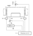
特に、本実施形態では、図5に示すように、制御部110のプロセスコントローラ111は、バッファ室5a,5bのゲートバルブGのアクチュエータ121、排気配管62の排気速度調整バルブ63、真空ポンプ64、ガス供給配管66の流量調節バルブ67を制御することにより、第1の搬送室11と第2の搬送室21との間の雰囲気の混合を防止しつつ、第1の搬送室11と第2の搬送室21との間のウエハWの搬送を行う。すなわち、これらバッファ室5a,5bが第1の搬送室11および第2の搬送室21のいずれか一方とのみ連通し、その内部が連通した搬送室内の圧力と適合するように、第1の搬送室11側のゲートバルブGの開閉、第2の搬送室21側のゲートバルブGの開閉、およびバッファ室5a,5b内の圧力を制御し、第1の搬送室11と第2の搬送室12との間を遮断しつつ、これらの間のウエハWの搬送を行えるようにする制御する。
In particular, in the present embodiment, as shown in FIG. 5, the
真空処理システム1は、このようにPVD処理を行うPVD処理チャンバとCVD処理を行うCVD処理チャンバとを有しており、PVD処理とCVD処理とを真空を破らずに連続的に行うものであるが、このようなPVD処理とCVD処理とが混在するアプリケーションとしては、コンタクト部の成膜および配線の成膜を挙げることができる。
The
コンタクト部の成膜の具体例としては、下地のシリコンまたはシリサイドの上に、まずCVD−Ti膜を成膜し、引き続きPVD−Ti膜を成膜し、さらにその上にPVD−Cu膜を成膜するものを挙げることができる。この場合には、第2の処理部3のCVD処理チャンバ22,23をCVD−Ti成膜用にし、第1の処理部2のPVD処理チャンバ12〜15のいずれか2つ、例えばPVD処理チャンバ12,13をPVD−Ti成膜用に、他の2つ、例えばPVD処理チャンバ14,15をPVD−Cu成膜用にすることができる。CVD−Ti成膜の後にCVD−TiN膜を成膜してもよく、この場合にはCVD処理チャンバ22,23の一方をCVD−Ti成膜用に、他方をCVD−TiN膜成膜用にすればよい。
As a specific example of the film formation of the contact portion, a CVD-Ti film is first formed on the underlying silicon or silicide, then a PVD-Ti film is formed, and a PVD-Cu film is further formed thereon. Mention may be made of membranes. In this case, the
また、配線の成膜の具体例としては、下地の金属膜、例えばW膜の上に、まずCVD−TiN膜を成膜し、引き続きPVD−Ti膜を成膜し、さらにその上にPVD−Cu膜を成膜するものを挙げることができる。この場合には、第2の処理部3のCVD処理チャンバ22,23をCVD−TiN成膜用にし、第1の処理部2のPVD処理チャンバ12〜15のいずれか2つ、例えばPVD処理チャンバ12,13をPVD−Ti成膜用に、他の2つ、例えばPVD処理チャンバ14,15をPVD−Cu成膜用にすることができる。
As a specific example of the formation of the wiring, a CVD-TiN film is first formed on an underlying metal film, for example, a W film, and then a PVD-Ti film is further formed. The thing which forms Cu film | membrane can be mentioned. In this case, the
次に、このような真空処理システム1における処理動作を上記コンタクト部の成膜を例にとって説明する。
まず、いずれかのキャリアCから搬入出用搬送機構36によりウエハWを取り出してロードロック室6aに搬入する。次いでロードロック室6aを真空排気して第2の搬送室21と同程度の圧力にした後、第2の搬送室21側の第2の搬送機構26によりロードロック室6aのウエハWを取り出し、CVD処理チャンバ22,23のいずれかに搬入する。そして、その中でCVD−Ti膜の成膜を行う。このときの成膜処理は、圧力を、上述したように1×101〜1×10³Pa(約1×10⁻¹〜1×101Torr)程度に保持しつつ行われる。一般的に、CVD処理は処理チャンバ内において汚染物質が多量に発生するため、汚染物質が第2の搬送室21に拡散してクロスコンタミネーションすることを防止する観点からは、第2の搬送室21の圧力をCVD処理チャンバ内の圧力より高く設定することが必要となる。
Next, the processing operation in the
First, the wafer W is taken out from one of the carriers C by the loading /
成膜が終了した後、処理が行われていたCVD処理チャンバから第2の搬送機構26によりウエハWを第2の搬送室21内に取り出し、引き続きウエハWを第2の搬送室からバッファ室5aに搬入する。このとき、ウエハWがバッファ室5aに搬入されるに先立って、バッファ室5a内の圧力が第2の搬送室21に適合した圧力に制御され、次いで、第2の搬送室21とバッファ5aとの間のゲートバルブGが開放され、第2の搬送機構26によりウエハWがバッファ室5aに搬入され、載置台68に載置される。このときの第2の搬送室21およびバッファ室5aの圧力は、上述したように1×101〜1×10³Pa(約1×10⁻¹〜1×101Torr)程度に保持される。この場合に、第2の搬送室21の汚染成分をバッファ室5aに極力拡散させない観点からはバッファ室5aの圧力を第2の搬送室21の圧力よりも高くしてバッファ室5aから第2の搬送室21へのガス流を形成することが好ましい。
After the film formation is completed, the wafer W is taken out from the CVD processing chamber in which the process has been performed into the
その後、ウエハWがバッファ室5aの載置台68に載置された状態で、第2の搬送室21側のゲートバルブGを閉じてバッファ室5aを密閉状態とし、その中の圧力が第1の搬送室11の圧力に適合した圧力に制御され、次いで、バッファ室5aと第1の搬送室11との間のゲートバルブGが開放され、第1の搬送機構16によりバッファ室5a内のウエハWを第1の搬送室11へ取り出す。このとき、第1の搬送室11およびバッファ室5aの圧力は、上述したように、1×10⁻⁷〜1×10⁻³Pa(約1×10⁻⁹〜10×10−5Torr)程度に保持される。
Thereafter, in a state where the wafer W is mounted on the mounting table 68 of the
この際の第1および第2の搬送室の圧力、PVD処理チャンバの圧力、CVD処理チャンバの圧力、バッファ室の圧力を模式的に示すと、図6に示すようになる。 FIG. 6 schematically shows the pressure in the first and second transfer chambers, the pressure in the PVD processing chamber, the pressure in the CVD processing chamber, and the pressure in the buffer chamber at this time.
バッファ室5aから取り出されたウエハWは、PVD処理チャンバ12,13のいずれかに搬入され、その中でPVD−Ti膜の成膜処理が行われる。PVD−Ti膜の成膜終了後、第1の搬送機構16によりウエハWがPVD処理チャンバ14,15のいずれかに搬送され、そこでPVD−Cu膜の成膜処理が行われる。
The wafer W taken out from the
PVD−Cu膜の成膜終了後、第1の搬送機構16によりウエハWを第1の搬送室11へ取り出し、引き続きウエハWを第1の搬送室11からバッファ室5bに搬入する。このとき、ウエハWがバッファ室5bに搬入されるに先立って、バッファ室5b内の圧力が第1の搬送室11に適合した圧力に制御され、次いで、第1の搬送室11とバッファ5bとの間のゲートバルブGが開放され、第1の搬送機構16によりウエハWがバッファ室5bに搬入され、載置台68に載置される。その後、ウエハWがバッファ室5bの載置台68にされた状態で、第1の搬送室11側のゲートバルブGを閉じてバッファ室5bを密閉状態とし、その中の圧力が第2の搬送室21の圧力に適合した圧力に制御され、次いで、バッファ室5bと第2の搬送室21との間のゲートバルブGが開放され、第2の搬送機構26によりバッファ室5b内のウエハWを第2の搬送室21へ取り出す。
After the film formation of the PVD-Cu film is completed, the wafer W is taken out to the
そして、第2の搬送機構26によりウエハWをロードロック室6bに搬入し、ロードロック室6b内を大気圧にした後、搬入出用搬送機構36によりウエハWをいずれかのキャリアCに収納する。
Then, after the wafer W is loaded into the
以上のように、本実施形態では、真空処理システム1を、高真空での処理であるPVD成膜処理を行うための第1の処理部2と、高圧での処理であるCVD成膜処理を行うための第2の処理部3とに分け、第1の処理部2の第1の搬送室11と第2の処理部3の第2の搬送室21とをそれぞれの処理に適合した圧力に固定し、これら第1の搬送室11と第2の搬送室21との間に、ウエハWが収容可能で、かつその内部の圧力調整が可能なバッファ室5a(5b)を設け、ウエハWを第1の搬送室11および第2の搬送室21のいずれか一方から他方へ搬送する際に、ゲートバルブGを閉じた状態で、バッファ室5a(5b)の圧力を第1の搬送室11および第2の搬送室21のうちウエハWが存在するほうの圧力に適合させ、当該ウエハWの存在する搬送室とバッファ室5a(5b)との間のゲートバルブGを開放してこれらの間を選択的に連通させて、ウエハWをバッファ室5a(5b)へ搬入し、ゲートバルブGを閉じてバッファ室5a(5b)を第1および第2の搬送室11,12から遮断し、その状態でバッファ室5a(5b)の圧力を他方の搬送室の圧力に適合させ、バッファ室バッファ室5a(5b)と他方の搬送室との間のゲートバルブGを開放してウエハWをバッファ室5a(5b)から他方の搬送室へ搬送するように制御するようにしたので、バッファ室5a(5b)によって、第1の搬送室11と第2の搬送室21の雰囲気の遮断を行えるとともに、バッファ室5a(5b)の圧力を調整することにより、第1の搬送室11と第2の搬送室21の間のウエハWの搬送が可能となる。このため、バッファ室5a(5b)の存在により、CVD処理チャンバからPVD処理チャンバへのクロスコンタミネーションを確実に防止することができるとともに、2つの搬送室の圧力を変動させる必要がなく、第1の搬送室11と第2の搬送室21との間でウエハWを搬送させる際のみ体積の小さいバッファ室5a,5bの圧力を調整を行えばよいので、スループットを低下させずに成膜処理を行うことができる。
As described above, in the present embodiment, the
また、上述したように、CVD処理は一般的に未反応ガスや反応生成物等の汚染成分が発生するが、CVD処理を行う第2の処理部3の第2の搬送室21の圧力をCVD処理チャンバ22,23内の圧力よりも高くなるように圧力制御することにより、CVD処理チャンバ22,23からの汚染成分の拡散を極力防止することができ、クロスコンタミネーションをより効果的に防止することができる。このように搬送室の圧力を高くすると、PVD処理に適合する高真空から圧力がかけ離れる方向となり、従来は、クロスコンタミネーション防止のための圧力調整の時間が長くならざるを得なかったが、本実施形態では、バッファ室5a,5bの圧力調整のみでよいため、このような場合でもスループットは殆ど低下しない。
In addition, as described above, the CVD process generally generates contaminant components such as unreacted gas and reaction products, but the pressure in the
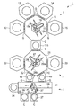
なお、本発明は上記実施形態に限定されることなく、本発明の思想の範囲内で種々変形可能である。例えば、上記実施形態ではバッファ室を2つ設けた例を示したが、図7に示すように、第1の搬送室11と第2の搬送室21との間に、1つのバッファ室115を設けるようにしてもよい。バッファ室の数が多いほどスループットが向上するため好ましいが、バッファ室が多くなると装置スペースが大きくなり装置コストも高くなるため、スループットが問題ない場合にはバッファ室は1個でよい。
In addition, this invention is not limited to the said embodiment, A various deformation | transformation is possible within the range of the thought of this invention. For example, in the above embodiment, an example in which two buffer chambers are provided has been described. However, as illustrated in FIG. 7, one
また、上記実施形態では、第1の処理部に4つのPVD処理チャンバを設け、第2の処理部に2つのCVD処理チャンバを設けた例について示したが、第1の処理部に4つのCVD処理チャンバを設け、第2の処理部に2つのPVD処理チャンバを設けるようにしてもよい。また、各処理部の処理チャンバの数は上記実施形態に限定されるものではなく、処理に応じて適宜調整すればよい。さらにまた、上記実施形態では、CVD処理チャンバで成膜する材料としてTiおよびTiNを例にとり、PVD処理チャンバで成膜する材料としてTi、Cuを例にとって説明したが、これに限定されるものではなく、CVD処理チャンバで成膜する材料としてその他に例えばWやWNを挙げることができ、PVD処理チャンバで成膜する材料としてその他にTaやTaNを挙げることができる。さらに、相対的に高圧の処理チャンバとしてCVD処理チャンバを例にとり、相対的に低圧の処理チャンバとしてPVD処理チャンバを例にとって説明したが、これに限るものではない。例えば、Cu膜を成膜する際のシード用下地として形成することができるRu膜の成膜はCVDにより行われるが、CVD−Ruでは成膜の際に汚染成分が殆ど生成されず、上記PVDと同程度の高真空(低圧)で処理可能であるため、CVD−Ruを成膜する処理チャンバは、相対的に低圧で真空処理を行う第1の処理チャンバとして用いることが可能である。 In the above embodiment, an example in which four PVD processing chambers are provided in the first processing unit and two CVD processing chambers are provided in the second processing unit has been described. However, four CVD processes are provided in the first processing unit. A processing chamber may be provided, and two PVD processing chambers may be provided in the second processing unit. Further, the number of processing chambers in each processing unit is not limited to the above embodiment, and may be adjusted as appropriate according to the processing. Furthermore, in the above embodiment, Ti and TiN have been described as examples of materials to be formed in the CVD processing chamber, and Ti and Cu have been described as examples of materials to be formed in the PVD processing chamber. However, the present invention is not limited to this. In addition, for example, W and WN can be cited as other materials for forming a film in the CVD processing chamber, and Ta and TaN can be mentioned as other materials for forming a film in the PVD processing chamber. Further, although a CVD process chamber has been described as an example of a relatively high pressure process chamber and a PVD process chamber has been described as an example of a relatively low pressure process chamber, the present invention is not limited thereto. For example, a Ru film that can be formed as a seed base for forming a Cu film is formed by CVD. However, in CVD-Ru, almost no contamination component is generated during film formation, and the PVD Therefore, the processing chamber for forming a CVD-Ru film can be used as a first processing chamber for performing vacuum processing at a relatively low pressure.
さらにまた、上記実施形態では、真空処理として成膜処理を行う場合を例にとって説明したが、成膜処理に限らず、他の真空処理にも同様に適用することができる。 Furthermore, in the above embodiment, the case where the film forming process is performed as the vacuum process has been described as an example. However, the present invention is not limited to the film forming process, and can be similarly applied to other vacuum processes.
1……真空処理システム
2……第1の処理部
3……第2の処理部
4……搬入出部
5a,5b,115……バッファ室
6a,6b……ロードロック室
11……第1の搬送室
12,13,14,15……PVD処理チャンバ
21……第2の搬送室
22,23……CVD処理チャンバ
26……第2の搬送機構
62……排気配管
63……排気速度調整バルブ
64……真空ポンプ
66……ガス導入配管
67……流量調節バルブ
68……載置台
110……制御部
111……プロセスコントローラ
113……記憶部
G……ゲートバルブ
W……半導体ウエハ
DESCRIPTION OF
Claims (11)
相対的に高圧で被処理体に対して真空処理を行う第2の処理チャンバと、前記第2の処理チャンバが接続され、被処理基板を前記第2の処理チャンバに対して搬入出する搬送機構を備え、その内部が前記第2の処理チャンバの処理圧力と適合した真空度に調整される第2の搬送室と、を有する第2の処理部と、
前記第1の搬送室および前記第2の搬送室の間にゲートバルブを介して設けられ、その内部に被処理基板が収容可能で、かつその内部が圧力調整可能なバッファ室と、
被処理基板を前記第1の搬送室および前記第2の搬送室のいずれか一方から他方へ搬送する際に、前記ゲートバルブを閉じた状態で、前記バッファ室の圧力を前記第1の搬送室および前記第2の搬送室のうち被処理基板が存在するほうの圧力に適合させ、当該被処理基板が存在する搬送室と前記バッファ室との間のゲートバルブを開放してこれらの間を選択的に連通させて、被処理基板を前記バッファ室へ搬入し、前記ゲートバルブを閉じて前記バッファ室を前記第1および第2の搬送室から遮断し、その状態で前記バッファ室の圧力を他方の搬送室の圧力に適合させ、前記バッファ室と前記他方の搬送室との間のゲートバルブを開放して被処理基板を前記バッファ室から他方の搬送室へ搬送するように制御する制御機構と
を具備する真空処理システム。 A first processing chamber that performs vacuum processing on a substrate to be processed at a relatively low pressure, and a transfer mechanism that connects the first processing chamber and carries the substrate into and out of the first processing chamber. A first transfer section having a first transfer chamber whose inside is adjusted to a degree of vacuum compatible with the processing pressure of the first processing chamber,
A second processing chamber that performs vacuum processing on the object to be processed at a relatively high pressure, and a transfer mechanism that connects the second processing chamber and carries the substrate to be processed in and out of the second processing chamber. And a second transfer chamber having an inside adjusted to a degree of vacuum adapted to the processing pressure of the second processing chamber,
A buffer chamber provided between the first transfer chamber and the second transfer chamber via a gate valve, in which a substrate to be processed can be accommodated, and the pressure inside thereof can be adjusted;
When the substrate to be processed is transferred from one of the first transfer chamber and the second transfer chamber to the other, the pressure in the buffer chamber is changed to the first transfer chamber with the gate valve closed. In addition, it is adapted to the pressure of the second transfer chamber where the substrate to be processed exists, and the gate valve between the transfer chamber where the substrate to be processed exists and the buffer chamber is opened to select between these The substrate is carried into the buffer chamber, the gate valve is closed, the buffer chamber is shut off from the first and second transfer chambers, and the pressure in the buffer chamber is changed to the other in this state. A control mechanism adapted to transfer the substrate to be processed from the buffer chamber to the other transfer chamber by adapting to the pressure of the transfer chamber and opening the gate valve between the buffer chamber and the other transfer chamber; Vacuum processing System.
相対的に高圧で被処理体に対して真空処理を行う第2の処理チャンバと、前記第2の処理チャンバが接続され、被処理基板を前記第2の処理チャンバに対して搬入出する搬送機構を備え、その内部が前記第2の処理チャンバの処理圧力と適合した真空度に調整される第2の搬送室と、を有する第2の処理部と、
を具備する真空処理システムにおいて、被処理基板を前記第1の搬送室および前記第2の搬送室のいずれか一方から他方へ搬送する基板搬送方法であって、
前記第1の搬送室と前記第2の搬送室との間にゲートバルブを介して、その内部に被処理体を収容可能で、かつその内部が圧力調整可能なバッファ室を設け、
前記ゲートバルブを閉じた状態で、前記バッファ室の圧力を前記第1の搬送室および前記第2の搬送室のうち被処理基板が存在するほうの圧力に適合させ、当該被処理基板が存在する搬送室と前記バッファ室との間のゲートバルブを開放してこれらの間を選択的に連通させて、被処理基板を前記バッファ室へ搬入し、前記ゲートバルブを閉じて前記バッファ室を前記第1および第2の搬送室から遮断し、その状態で前記バッファ室の圧力を他方の搬送室の圧力に適合させ、前記バッファ室と前記他方の搬送室との間のゲートバルブを開放して被処理基板を前記バッファ室から他方の搬送室へ搬送することを特徴とする基板搬送方法。 A first processing chamber that performs vacuum processing on a substrate to be processed at a relatively low pressure, and a transfer mechanism that connects the first processing chamber and carries the substrate into and out of the first processing chamber. A first transfer section having a first transfer chamber whose inside is adjusted to a degree of vacuum compatible with the processing pressure of the first processing chamber,
A second processing chamber that performs vacuum processing on the object to be processed at a relatively high pressure, and a transfer mechanism that connects the second processing chamber and carries the substrate to be processed in and out of the second processing chamber. And a second transfer chamber having an inside adjusted to a degree of vacuum adapted to the processing pressure of the second processing chamber,
In the vacuum processing system comprising: a substrate transfer method for transferring a substrate to be processed from either one of the first transfer chamber and the second transfer chamber to the other,
A buffer chamber is provided between the first transfer chamber and the second transfer chamber via a gate valve, the object to be processed can be accommodated therein, and the pressure inside thereof can be adjusted,
With the gate valve closed, the pressure in the buffer chamber is adapted to the pressure of the first transfer chamber and the second transfer chamber where the substrate to be processed exists, and the substrate to be processed exists. A gate valve between the transfer chamber and the buffer chamber is opened to selectively communicate between them, the substrate to be processed is loaded into the buffer chamber, the gate valve is closed, and the buffer chamber is moved to the first chamber. Shut off from the first and second transfer chambers, and adjust the pressure in the buffer chamber to the pressure in the other transfer chamber in this state, and open the gate valve between the buffer chamber and the other transfer chamber. A substrate transfer method comprising transferring a processing substrate from the buffer chamber to the other transfer chamber.
相対的に低圧で被処理基板に対して真空処理を行う第1の処理チャンバと、前記第1の処理チャンバが接続され、被処理基板を前記第1の処理チャンバに対して搬入出する搬送機構を備え、その内部が前記第1の処理チャンバの処理圧力と適合した真空度に調整される第1の搬送室と、を有する第1の処理部と、
相対的に高圧で被処理体に対して真空処理を行う第2の処理チャンバと、前記第2の処理チャンバが接続され、被処理基板を前記第2の処理チャンバに対して搬入出する搬送機構を備え、その内部が前記第2の処理チャンバの処理圧力と適合した真空度に調整される第2の搬送室と、を有する第2の処理部と、
前記第1の搬送室と前記第2の搬送室との間にゲートバルブを介して、その内部に被処理体を収容可能で、かつその内部が圧力調整可能なバッファ室と
を具備する真空処理システムを制御するプログラムが記憶された記憶媒体であって、
前記プログラムは、実行時に、被処理基板を前記第1の搬送室および前記第2の搬送室のいずれか一方から他方へ搬送する基板搬送方法であって、前記ゲートバルブを閉じた状態で、前記バッファ室の圧力を前記第1の搬送室および前記第2の搬送室のうち被処理基板が存在するほうの圧力に適合させ、当該被処理基板が存在する搬送室と前記バッファ室との間のゲートバルブを開放してこれらの間を選択的に連通させて、被処理基板を前記バッファ室へ搬入し、前記ゲートバルブを閉じて前記バッファ室を前記第1および第2の搬送室から遮断し、その状態で前記バッファ室の圧力を他方の搬送室の圧力に適合させ、前記バッファ室と前記他方の搬送室との間のゲートバルブを開放して被処理基板を前記バッファ室から他方の搬送室へ搬送する基板搬送方法が行われるように、コンピュータに前記真空処理システムを制御させることを特徴とする記憶媒体。 Works on the computer,
A first processing chamber that performs vacuum processing on a substrate to be processed at a relatively low pressure, and a transfer mechanism that connects the first processing chamber and carries the substrate into and out of the first processing chamber. A first transfer section having a first transfer chamber whose inside is adjusted to a degree of vacuum compatible with the processing pressure of the first processing chamber,
A second processing chamber that performs vacuum processing on the object to be processed at a relatively high pressure, and a transfer mechanism that connects the second processing chamber and carries the substrate to be processed in and out of the second processing chamber. And a second transfer chamber having an inside adjusted to a degree of vacuum adapted to the processing pressure of the second processing chamber,
A vacuum process comprising a buffer chamber in which the object to be processed can be accommodated and the pressure inside thereof can be adjusted via a gate valve between the first transfer chamber and the second transfer chamber. A storage medium storing a program for controlling the system,
The program is a substrate transfer method for transferring a substrate to be processed from one of the first transfer chamber and the second transfer chamber to the other at the time of execution, with the gate valve closed, The pressure of the buffer chamber is adapted to the pressure of the first transfer chamber and the second transfer chamber where the substrate to be processed exists, and between the transfer chamber where the substrate to be processed exists and the buffer chamber. The gate valve is opened to selectively communicate between them, the substrate to be processed is carried into the buffer chamber, the gate valve is closed, and the buffer chamber is shut off from the first and second transfer chambers. In this state, the pressure in the buffer chamber is adapted to the pressure in the other transfer chamber, the gate valve between the buffer chamber and the other transfer chamber is opened, and the substrate to be processed is transferred from the buffer chamber to the other transfer chamber. Transport to room As substrate transfer method is carried out that, the storage medium, characterized in that to control the vacuum processing system to a computer.
Priority Applications (5)
| Application Number | Priority Date | Filing Date | Title |
|---|---|---|---|
| JP2007233724A JP2009062604A (en) | 2007-09-10 | 2007-09-10 | Vacuum treatment system, and method for carrying substrate |
| PCT/JP2008/065672 WO2009034869A1 (en) | 2007-09-10 | 2008-09-01 | Vacuum processing system and substrate transfer method |
| KR1020097027030A KR20100065127A (en) | 2007-09-10 | 2008-09-01 | Vacuum processing system and substrate transfer method |
| CN200880023081A CN101688296A (en) | 2007-09-10 | 2008-09-01 | Vacuum processing system and substrate transfer method |
| TW97134559A TW200931577A (en) | 2007-09-10 | 2008-09-09 | Vacuum treatment system, and method for carrying substrate |
Applications Claiming Priority (1)
| Application Number | Priority Date | Filing Date | Title |
|---|---|---|---|
| JP2007233724A JP2009062604A (en) | 2007-09-10 | 2007-09-10 | Vacuum treatment system, and method for carrying substrate |
Publications (2)
| Publication Number | Publication Date |
|---|---|
| JP2009062604A true JP2009062604A (en) | 2009-03-26 |
| JP2009062604A5 JP2009062604A5 (en) | 2010-08-26 |
Family
ID=40451878
Family Applications (1)
| Application Number | Title | Priority Date | Filing Date |
|---|---|---|---|
| JP2007233724A Ceased JP2009062604A (en) | 2007-09-10 | 2007-09-10 | Vacuum treatment system, and method for carrying substrate |
Country Status (5)
| Country | Link |
|---|---|
| JP (1) | JP2009062604A (en) |
| KR (1) | KR20100065127A (en) |
| CN (1) | CN101688296A (en) |
| TW (1) | TW200931577A (en) |
| WO (1) | WO2009034869A1 (en) |
Cited By (9)
| Publication number | Priority date | Publication date | Assignee | Title |
|---|---|---|---|---|
| WO2011040538A1 (en) * | 2009-10-02 | 2011-04-07 | 東京エレクトロン株式会社 | Substrate processing system |
| JP2011124564A (en) * | 2009-11-12 | 2011-06-23 | Hitachi High-Technologies Corp | System and method for vacuum processing of semiconductor substrate to be processed |
| JP2012044175A (en) * | 2010-08-12 | 2012-03-01 | Samsung Electronics Co Ltd | Substrate processing system |
| JP2012138542A (en) * | 2010-12-28 | 2012-07-19 | Hitachi High-Technologies Corp | Vacuum processing apparatus |
| JP2013115393A (en) * | 2011-12-01 | 2013-06-10 | Hitachi High-Technologies Corp | Vacuum processing apparatus and operation method of vacuum processing apparatus |
| KR20210088153A (en) * | 2020-01-06 | 2021-07-14 | 삼성전자주식회사 | Air lock device and control system for prevent gas leaking in bays |
| CN113122812A (en) * | 2021-04-20 | 2021-07-16 | 郑州航空工业管理学院 | Physical vapor deposition material processing equipment |
| JP2021172491A (en) * | 2020-04-24 | 2021-11-01 | 島根島津株式会社 | Auto-storing module and auto-storing system |
| WO2023121245A1 (en) * | 2021-12-23 | 2023-06-29 | 주식회사 에이치피에스피 | Wafer treatment device for combined high-pressure process and vacuum process, and wafer treatment method using reduced pressure |
Families Citing this family (16)
| Publication number | Priority date | Publication date | Assignee | Title |
|---|---|---|---|---|
| CN101958231A (en) * | 2010-05-06 | 2011-01-26 | 东莞宏威数码机械有限公司 | Gaseous environment buffer device |
| KR101254721B1 (en) * | 2011-03-30 | 2013-04-15 | 삼성전자주식회사 | EFEM Buffer Module |
| JP5750328B2 (en) * | 2011-07-20 | 2015-07-22 | 株式会社ニューフレアテクノロジー | Vapor phase growth method and vapor phase growth apparatus |
| CN103184427A (en) * | 2011-12-28 | 2013-07-03 | 绿种子科技(潍坊)有限公司 | Thin film deposition apparatus and application method thereof |
| KR101375646B1 (en) * | 2012-06-18 | 2014-03-18 | 주식회사 씨엘디 | Apparatus for pressing a plate assembly and method thereof |
| KR101318929B1 (en) * | 2012-06-18 | 2013-10-17 | 주식회사 씨엘디 | Apparatus for pressing a plate assembly |
| JP6120621B2 (en) * | 2013-03-14 | 2017-04-26 | 株式会社日立ハイテクノロジーズ | Vacuum processing apparatus and operation method thereof |
| CN104421437B (en) * | 2013-08-20 | 2017-10-17 | 中微半导体设备(上海)有限公司 | Movable valve, portable shielding door and vacuum flush system |
| KR101649356B1 (en) * | 2014-01-20 | 2016-08-18 | 주식회사 풍산 | Semiconductor Substrate Processing Apparatus |
| JP2017028209A (en) * | 2015-07-27 | 2017-02-02 | 東京エレクトロン株式会社 | Substrate housing method and substrate processing device |
| JP6141479B1 (en) * | 2016-03-18 | 2017-06-07 | エスペック株式会社 | Drying equipment |
| CN106229287B (en) * | 2016-09-30 | 2019-04-05 | 厦门市三安光电科技有限公司 | For shifting the transposition head of microcomponent and the transfer method of microcomponent |
| CN110835739A (en) * | 2018-08-17 | 2020-02-25 | 中智(泰兴)电力科技有限公司 | 7-cavity vertical PECVD-PVD integrated silicon wafer coating process |
| CN110835735A (en) * | 2018-08-17 | 2020-02-25 | 中智(泰兴)电力科技有限公司 | 8-cavity horizontal HWCVD-PVD integrated silicon wafer coating process |
| JP7386738B2 (en) * | 2020-03-19 | 2023-11-27 | 東京エレクトロン株式会社 | Substrate transport method and substrate processing equipment |
| JP7344236B2 (en) * | 2021-02-08 | 2023-09-13 | キヤノントッキ株式会社 | Transport device, film forming device and control method |
Citations (3)
| Publication number | Priority date | Publication date | Assignee | Title |
|---|---|---|---|---|
| JPH04254349A (en) * | 1991-02-06 | 1992-09-09 | Sony Corp | Multichamber process apparatus |
| JPH07211761A (en) * | 1994-01-21 | 1995-08-11 | Tokyo Electron Ltd | Transfer of material to be treated in treating device |
| JP2003060008A (en) * | 2001-05-21 | 2003-02-28 | Tokyo Electron Ltd | Treatment apparatus, apparatus and method for transfer |
Family Cites Families (1)
| Publication number | Priority date | Publication date | Assignee | Title |
|---|---|---|---|---|
| JPH0793348B2 (en) * | 1989-05-19 | 1995-10-09 | アプライド マテリアルズ インコーポレーテッド | Multi-chamber vacuum processing apparatus and multi-chamber vacuum semiconductor wafer processing apparatus |
-
2007
- 2007-09-10 JP JP2007233724A patent/JP2009062604A/en not_active Ceased
-
2008
- 2008-09-01 CN CN200880023081A patent/CN101688296A/en active Pending
- 2008-09-01 WO PCT/JP2008/065672 patent/WO2009034869A1/en active Application Filing
- 2008-09-01 KR KR1020097027030A patent/KR20100065127A/en active Search and Examination
- 2008-09-09 TW TW97134559A patent/TW200931577A/en unknown
Patent Citations (3)
| Publication number | Priority date | Publication date | Assignee | Title |
|---|---|---|---|---|
| JPH04254349A (en) * | 1991-02-06 | 1992-09-09 | Sony Corp | Multichamber process apparatus |
| JPH07211761A (en) * | 1994-01-21 | 1995-08-11 | Tokyo Electron Ltd | Transfer of material to be treated in treating device |
| JP2003060008A (en) * | 2001-05-21 | 2003-02-28 | Tokyo Electron Ltd | Treatment apparatus, apparatus and method for transfer |
Cited By (12)
| Publication number | Priority date | Publication date | Assignee | Title |
|---|---|---|---|---|
| WO2011040538A1 (en) * | 2009-10-02 | 2011-04-07 | 東京エレクトロン株式会社 | Substrate processing system |
| JP2011124564A (en) * | 2009-11-12 | 2011-06-23 | Hitachi High-Technologies Corp | System and method for vacuum processing of semiconductor substrate to be processed |
| JP2012044175A (en) * | 2010-08-12 | 2012-03-01 | Samsung Electronics Co Ltd | Substrate processing system |
| JP2012138542A (en) * | 2010-12-28 | 2012-07-19 | Hitachi High-Technologies Corp | Vacuum processing apparatus |
| JP2013115393A (en) * | 2011-12-01 | 2013-06-10 | Hitachi High-Technologies Corp | Vacuum processing apparatus and operation method of vacuum processing apparatus |
| KR20210088153A (en) * | 2020-01-06 | 2021-07-14 | 삼성전자주식회사 | Air lock device and control system for prevent gas leaking in bays |
| KR102618825B1 (en) | 2020-01-06 | 2023-12-27 | 삼성전자주식회사 | Air lock device and control system for prevent gas leaking in bays |
| JP2021172491A (en) * | 2020-04-24 | 2021-11-01 | 島根島津株式会社 | Auto-storing module and auto-storing system |
| JP7420350B2 (en) | 2020-04-24 | 2024-01-23 | 島根島津株式会社 | Automatic storage module and automatic storage system |
| CN113122812A (en) * | 2021-04-20 | 2021-07-16 | 郑州航空工业管理学院 | Physical vapor deposition material processing equipment |
| CN113122812B (en) * | 2021-04-20 | 2023-06-09 | 郑州航空工业管理学院 | Physical vapor deposition material processing equipment |
| WO2023121245A1 (en) * | 2021-12-23 | 2023-06-29 | 주식회사 에이치피에스피 | Wafer treatment device for combined high-pressure process and vacuum process, and wafer treatment method using reduced pressure |
Also Published As
| Publication number | Publication date |
|---|---|
| CN101688296A (en) | 2010-03-31 |
| KR20100065127A (en) | 2010-06-15 |
| TW200931577A (en) | 2009-07-16 |
| WO2009034869A1 (en) | 2009-03-19 |
Similar Documents
| Publication | Publication Date | Title |
|---|---|---|
| JP2009062604A (en) | Vacuum treatment system, and method for carrying substrate | |
| JP4916140B2 (en) | Vacuum processing system | |
| JP5208948B2 (en) | Vacuum processing system | |
| TWI407497B (en) | Multi-region processing system and heads | |
| JP2008060577A (en) | Substrate-processing apparatus having buffer mechanism, and substrate-transfer apparatus | |
| JP2002141293A (en) | Manufacturing method of semiconductor | |
| US20160284581A1 (en) | Method of Manufacturing Semiconductor Device | |
| JP4634918B2 (en) | Vacuum processing equipment | |
| JP2010123733A (en) | Substrate processing apparatus and processing method thereof, and storage medium | |
| KR20140034318A (en) | Method and apparatus for cooling subject to be processed, and computer-readable storage medium | |
| JP4541931B2 (en) | Semiconductor device manufacturing method and semiconductor manufacturing apparatus | |
| JPWO2013183437A1 (en) | Gas processing method | |
| JP2003017478A (en) | Vacuum treatment apparatus and method | |
| JP4646941B2 (en) | Substrate processing apparatus and method for stabilizing state in processing chamber | |
| CN110911261B (en) | Substrate processing apparatus, method of manufacturing semiconductor device, and recording medium | |
| JP2004339566A (en) | Substrate treatment apparatus | |
| JP5436763B2 (en) | Airtight module and exhaust method of the airtight module | |
| KR102588608B1 (en) | Method for treating a substrate | |
| JP6417916B2 (en) | Substrate transport method, substrate processing apparatus, and storage medium | |
| JP4270413B2 (en) | Process equipment | |
| WO2020241599A1 (en) | Substrate processing system and method for controlling substrate processing system | |
| JP2008024975A (en) | Semi-conductor manufacturing equipment | |
| JP2017210643A (en) | Evacuation method | |
| JP2009260022A (en) | Substrate treatment unit, and substrate treatment apparatus | |
| JP2005333076A (en) | Load locking device, processing system and its using method |
Legal Events
| Date | Code | Title | Description |
|---|---|---|---|
| A521 | Written amendment |
Effective date: 20100708 Free format text: JAPANESE INTERMEDIATE CODE: A523 |
|
| A621 | Written request for application examination |
Free format text: JAPANESE INTERMEDIATE CODE: A621 Effective date: 20100708 |
|
| A131 | Notification of reasons for refusal |
Free format text: JAPANESE INTERMEDIATE CODE: A131 Effective date: 20130122 |
|
| A521 | Written amendment |
Free format text: JAPANESE INTERMEDIATE CODE: A523 Effective date: 20130321 |
|
| A01 | Written decision to grant a patent or to grant a registration (utility model) |
Free format text: JAPANESE INTERMEDIATE CODE: A01 Effective date: 20130423 |
|
| A045 | Written measure of dismissal of application |
Free format text: JAPANESE INTERMEDIATE CODE: A045 Effective date: 20130827 |