JP4671908B2 - Building structure - Google Patents
Building structure Download PDFInfo
- Publication number
- JP4671908B2 JP4671908B2 JP2006142222A JP2006142222A JP4671908B2 JP 4671908 B2 JP4671908 B2 JP 4671908B2 JP 2006142222 A JP2006142222 A JP 2006142222A JP 2006142222 A JP2006142222 A JP 2006142222A JP 4671908 B2 JP4671908 B2 JP 4671908B2
- Authority
- JP
- Japan
- Prior art keywords
- floor
- building
- diaphragm floor
- side wall
- reactor
- Prior art date
- Legal status (The legal status is an assumption and is not a legal conclusion. Google has not performed a legal analysis and makes no representation as to the accuracy of the status listed.)
- Expired - Fee Related
Links
Images

Classifications
-
- Y—GENERAL TAGGING OF NEW TECHNOLOGICAL DEVELOPMENTS; GENERAL TAGGING OF CROSS-SECTIONAL TECHNOLOGIES SPANNING OVER SEVERAL SECTIONS OF THE IPC; TECHNICAL SUBJECTS COVERED BY FORMER USPC CROSS-REFERENCE ART COLLECTIONS [XRACs] AND DIGESTS
- Y02—TECHNOLOGIES OR APPLICATIONS FOR MITIGATION OR ADAPTATION AGAINST CLIMATE CHANGE
- Y02E—REDUCTION OF GREENHOUSE GAS [GHG] EMISSIONS, RELATED TO ENERGY GENERATION, TRANSMISSION OR DISTRIBUTION
- Y02E30/00—Energy generation of nuclear origin
- Y02E30/30—Nuclear fission reactors
Landscapes
- Buildings Adapted To Withstand Abnormal External Influences (AREA)
Description
本発明の技術分野は、建屋内の構造に関し、建屋内での重量構造物の建屋への設置構造に関するものである。 The technical field of the present invention relates to a structure in a building, and relates to a structure for installing a heavy structure in a building.
地盤から建屋への地震エネルギーを緩衝するためには、滑り型免震装置や積層ゴム型免震装置を地盤と建屋の間に介在させることが知られている(例えば、特許文献1参照)。 In order to buffer the seismic energy from the ground to the building, it is known to interpose a sliding-type seismic isolation device or a laminated rubber-type seismic isolation device between the ground and the building (for example, see Patent Document 1).
他の方法として、建屋を水槽内に置いて、その建屋と水槽内壁との間に水平用と上下用との各ばねダンパー装置を装備しておくことが知られている(例えば、特許文献2参照)。 As another method, it is known that a building is placed in a water tank, and horizontal and vertical spring damper devices are provided between the building and the water tank inner wall (for example, Patent Document 2). reference).
上記特許文献1,2のように、建屋を複数の免震装置で局部的に支持する構成は、垂直方向の支持が局部的に点在した形態と成るので、重量構造物を支持するには免震装置が局部で集中荷重を支持する必要性から一つ一つの免震装置が大型化する。そのため、建屋内の限られた空間内に設置されえる構造物に対して免震装置を装備採用しがたい要因がある。
As described in
原子炉建屋の場合には、その建屋に内蔵している原子炉格納容器は、垂直な側壁とその側壁に直行する略水平なダイアフラムフロアと称する床を原子炉格納容器内部に備えている。その床に重量構造物を設置することが考えられる。 In the case of a reactor building, the reactor containment vessel built in the building includes a vertical side wall and a floor called a substantially horizontal diaphragm floor that goes directly to the side wall inside the reactor containment vessel. It is conceivable to install a heavy structure on the floor.
ダイアフラムフロアは原子炉格納容器内を圧力抑制室内と原子炉圧力抑制室外との圧力差や周囲の温度の変化によって、変形したり伸縮したりして、過大な応力がダイアフラムフロアに発生しないように設計され設置されている。 The diaphragm floor is deformed and stretched by the pressure difference between the pressure containment chamber and the outside of the reactor pressure containment chamber and the change in ambient temperature, so that excessive stress is not generated on the diaphragm floor. Designed and installed.
その一方で、ダイアフラムフロアは変形し易いように設計されているので、そのダイアフラムフロアに重量構造物を建設設置すると、その重量構造物とダイアフラムフロアとの設置面の剛性が高くなって、ダイアフラムフロアが重量構造物の剛性で拘束を受けて変形や伸縮し易い機能が損なわれる。 On the other hand, since the diaphragm floor is designed to be easily deformed, when a heavy structure is constructed and installed on the diaphragm floor, the rigidity of the installation surface of the heavy structure and the diaphragm floor increases, and the diaphragm floor However, the function of being easily deformed and stretched due to the rigidity of the heavy structure is impaired.
そこでダイアフラムフロアに隣接する原子炉格納容器の垂直な側壁を重量構造物の一側壁に、そしてダイアフラムフロアを重量構造物の底壁13として、それぞれ共有して重量構造物をダイアフラムフロア上に構築することが考えられるが、これでもダイアフラムフロアが側壁と一体となるので、ダイアフラムフロアの自由な変形や伸縮を阻害する課題が生じる。
Therefore, the vertical structure side wall of the reactor containment adjacent to the diaphragm floor is used as one side wall of the heavy structure, and the diaphragm floor is used as the
原子炉格納容器の垂直な側壁を重量構造物の一側壁に共有した場合には、地震時の側壁への横荷重が過大になりがちである。 When the vertical side wall of the reactor containment vessel is shared with one side wall of the heavy structure, the lateral load on the side wall during an earthquake tends to be excessive.
このように本来必要なダイアフラムフロアの自由な変形や側壁への横荷重の過大化は原子炉格納容器の機能に無理を与える可能性が含まれる。 As described above, the free deformation of the diaphragm floor and the excessive lateral load on the side wall, which are originally necessary, include the possibility that the function of the reactor containment vessel may not be achieved.
したがって、本発明の目的は、建屋の床上に構造物を配置する際に、免震装置を用いることなく、その建屋に無理を与えないような構造の建屋を提供することにある Accordingly, an object of the present invention is to provide a building having a structure that does not force the building without using a seismic isolation device when placing the structure on the floor of the building.
本発明の課題の解決手段は、本発明は、建屋の床に構造物を滑り材を介して設置して前記床と前記構造物との間の相対的移動を許容してあることを特徴とした建屋であり、さらに好ましくは、前記構造物は前記建屋の側壁を共有する重量構造物であることを特徴とした建屋である。 According to a means for solving the problems of the present invention, the present invention is characterized in that a structure is installed on a floor of a building via a sliding material to allow relative movement between the floor and the structure. More preferably, the structure is a heavy structure that shares a side wall of the building.
他の解決手段は、建屋の側壁に発泡金属を設置し、前記発泡金属を設置した側壁を共有するように構造物を前記建屋の床から切り離して前記建屋に設置してあることを特徴とした建屋であり、さらに好ましくは、前記構造物は前記発泡金属を設置した側壁を共有する重量構造物であることを特徴とした建屋であり、一層好ましくは、建屋の床に構造物を滑り材を介して設置して前記床と前記構造物との間の相対的移動を許容してあることを特徴とした建屋である。 Another solution is characterized in that foam metal is installed on the side wall of the building, and the structure is installed on the building separately from the floor of the building so as to share the side wall on which the foam metal is installed. It is a building, and more preferably, the structure is a heavy structure that shares a side wall on which the foam metal is installed, and more preferably, the structure is placed on the floor of the building with a sliding material. The building is characterized in that it is installed to allow relative movement between the floor and the structure.
さらに他の解決手段は、前記のいずれかの建屋において、前記建屋は原子炉建屋であって、前記原子炉建屋は、原子炉格納容器を内蔵し、前記原子炉格納容器内には、床として圧力抑制室内外を区画するダイアフラムフロアを、側壁として前記ダイアフラムフロアに隣接して垂直な壁とを備えていることを特徴とした建屋である。 Still another solution is that, in any one of the above buildings, the building is a reactor building, and the reactor building contains a reactor containment vessel, and the reactor containment vessel includes a floor. The building is characterized in that a diaphragm floor partitioning the inside and outside of the pressure suppression chamber is provided with a vertical wall adjacent to the diaphragm floor as a side wall.
本発明は、建屋の床上に装備される構造物による建屋の床又は建屋の側壁又はその両方に対する無理な荷重や応力の発生を抑制して建屋の安全維持に寄与できる。 INDUSTRIAL APPLICABILITY The present invention can contribute to maintaining the safety of the building by suppressing the generation of excessive loads and stresses on the building floor and / or the side walls of the building by the structures equipped on the building floor.
本発明の実施例で採用される構造は、建屋の壁と床とを共有して設置する拘束条件の厳しい重量構造物において、重量構造物と床面を共有せず、床面上に金属板,レール,コロ等の滑り材を配置し、その上に重量構造物を配置する。重量構造物の自重のみ受け持つ構造とすることにより、設置床面であるダイアフラムフロアの変形が発生した場合、滑り材の効果により重量構造物が床面上を滑ることにより変形の影響を逃がし、直接床との拘束部が存在しないことにより、重量構造物の応力を低減することを特徴とする構造である。 The structure adopted in the embodiment of the present invention is a heavy structure with severe restraint conditions in which a building wall and a floor are installed in common. A heavy metal structure and a floor surface are not shared, and a metal plate is formed on the floor surface. A sliding material such as a rail, a roller, etc. is arranged, and a heavy structure is arranged thereon. When the diaphragm floor, which is the installation floor surface, is deformed by adopting a structure that only handles the weight of the heavy structure, the effect of the sliding material is eliminated by the sliding of the heavy structure on the floor surface due to the effect of the sliding material. The structure is characterized in that the stress of the heavy structure is reduced by the absence of the restraining portion with the floor.
本発明の他の実施例で採用される構造は、建屋のフロア面と重量構造物底面との間に滑り材となる金属板もしくはレール,コロを配し、また、壁面については、緩衝材となる発泡金属を埋め込む構造を有することを特徴とする構造である。 The structure adopted in another embodiment of the present invention is that a metal plate or a rail or roller serving as a sliding material is disposed between the floor surface of the building and the bottom surface of the heavy structure. It is a structure characterized by having the structure which embeds the foam metal which becomes.
本発明の各実施例は、重量構造物としてコンクリート製のプールを想定している。本発明の各実施例では、プール底面とダイアフラムフロア床面とは共有関係に無く、互いに切り離されている上、ダイアフラムフロア床面上に金属板,レール,コロ等の滑り材の中から滑り材として金属板を選択して配置し、ダイアフラムフロアは重量構造物の自重のみ受け持つ構造とすることにより、設置床面であるダイアフラムフロアの変形が発生した場合、滑り材の効果により重量構造物とダイアフラムフロアとの間で滑り作用が発生して変形の影響を逃がし、ダイアフラムフロアへの重量構造物の直接的な拘束部が存在しないことで、重量構造物によるダイアフラムフロアの拘束による応力の発生を低減することが可能となる。 Each embodiment of the present invention assumes a concrete pool as a heavy structure. In each of the embodiments of the present invention, the pool bottom surface and the diaphragm floor surface are not in a shared relationship and are separated from each other, and the sliding material is selected from sliding materials such as metal plates, rails, rollers, etc. on the diaphragm floor surface. The metal floor is selected and arranged, and the diaphragm floor is designed to handle only the weight of the heavy structure. When the diaphragm floor, which is the installation floor, is deformed, the heavy structure and the diaphragm are affected by the effect of the sliding material. Sliding action occurs between the floor and the effect of deformation, and there is no direct restraint part of the heavy structure on the diaphragm floor, reducing the generation of stress due to the restraint of the diaphragm floor by the heavy structure It becomes possible to do.
また、上下方向もしくは水平方向の荷重が発生した場合、直接床面との拘束部が存在しないため、荷重による過大な応力が発生することなく、壁については、発泡金属等の緩衝材を埋め込む構造を有することで、重量構造物及び建屋の壁部分にかかる荷重の影響を低減することが可能となる。特に重量構造物が液体を内包した構造物である場合には、構造物内に蓄えられた液体のスロッシングによる壁面への荷重の負荷を発泡金属の緩衝作用で緩和でき、建屋の安全に寄与できる。さらには、本発明の各実施例では従来の免振装置,耐震構造のような特殊な構造,機器,スペースを必要としないので、導入し易いという利点がある。 In addition, when a load in the vertical direction or horizontal direction occurs, there is no direct restraint with the floor surface, so there is no excessive stress caused by the load, and the wall is embedded with a cushioning material such as foam metal It becomes possible to reduce the influence of the load concerning a heavy structure and a wall part of a building. Especially when the heavy structure is a structure containing liquid, the load applied to the wall surface due to sloshing of the liquid stored in the structure can be mitigated by the cushioning action of the foam metal, contributing to the safety of the building . Furthermore, each embodiment of the present invention does not require a special structure, equipment, or space such as a conventional vibration isolator and earthquake-resistant structure, so that there is an advantage that it is easy to introduce.
以下、本発明の各実施例を図面を用いて詳細に説明する。 Hereinafter, embodiments of the present invention will be described in detail with reference to the drawings.
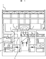
図1に示す建屋は、原子力発電所の原子炉建屋1である。原子炉建屋1内には、鉄筋コンクリート製の原子炉格納容器2が内蔵されている。原子炉格納容器2内には、原子炉圧力容器3などが格納され、放射能漏れなどが無いように密閉されている。
The building shown in FIG. 1 is a
原子炉格納容器2は、圧力抑制室7とドライウェルとの空間を区画する略水平なダイアフラムフロア5が構築されている。ダイアフラムフロア5は、鋼材の骨組みにコンクリートを施工して構築されている。この圧力抑制室7には冷却水9が底部に蓄えている。そして、この圧力抑制室7は、原子炉圧力容器3から過剰な蒸気や漏洩事故による蒸気がドライウェルから圧力抑制室7内の冷却水に吹き込まれてくると、その蒸気を冷却水9で凝縮及び冷却して原子炉格納容器2内の圧力の上昇を抑制する機能を担っている。
The
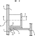
ダイアフラムフロア5は、図2のように、原子炉格納容器2の側壁4に近い端部が、その側壁4から突き出された支持ブラケット14上に、支持ブラケット14に対してダイアフラムフロア5は水平方向へ自由に動けるように搭載されて設置されている。したがって、原子炉格納容器2内の温度変化が生じるとダイアフラムフロア5は支持ブラケット14に対して水平方向へ自由に動いて伸縮することでダイアフラムフロア5に過大な応力の発生がない。
As shown in FIG. 2, the
また、図2のように、ダイアフラムフロア5と原子炉格納容器2の側壁4との間には、伸縮自在な金属ベローがシール15として設置されている。そのため、雰囲気の圧力抑制室内とドライウェル空間内との間の自由な往来はダイアフラムフロア5とシール15とで隔絶されている。シール15は伸縮自在であるので、ダイアフラムフロア5の自由な動きを拘束しない。
Further, as shown in FIG. 2, an extendable metal bellows is installed as a
また、蒸気漏洩事故が発生すると、圧力抑制室7とドライウェル8との間には圧力差が発生し、その発生に基づいてダイアフラムフロア5が上下に弾性的に変形する。即ち、ダイアフラムフロア5は変形しやすい様に、及び水平方向へ動き易いように構築されて、その変形や移動で破壊されること無く圧力差や温度差に対応できるようになっている。また、ダイアフラムフロア5は変形や動き易いように途中部分が下方から一切支持されていない。
In addition, when a steam leakage accident occurs, a pressure difference is generated between the pressure suppression chamber 7 and the
このような、建屋の床としてのダイアフラムフロア5上に鉄筋コンクリート製のプールを重量構造物として建設する際に、原子炉圧力容器3の垂直な側壁4を重量構造物6の一側壁として、及びダイアフラムフロア5を重量構造物6の底壁13として共有するように構築することが考えられえるが、そのような構築構造であると、ダイアフラムフロア5が側壁4や重量構造物6によって拘束されて自由に変形したり水平方向に動いたりすることが困難となってダイアフラムフロア5や重量構造物6に過剰な応力が発生し易くなる。
When a reinforced concrete pool is constructed as a heavy structure on the
そこで、図2のように、重量構造物6の底面に対面するダイアフラムフロア5の上面に滑り材としての金属板11,レール,コロ等から選択した金属板11をスタッドを用いてダイアフラムフロア5に設置する。その設置に際しては、ダイアフラムフロア5にコンクリートを施工する際に、金属板11の裏面に溶接固定しておいたスタッドをダイアフラムフロア5のコンクリートに埋設するようにして設置する。その金属板11は、ダイアフラムフロア5の変形を阻害しないように剛性が設定されている。
Therefore, as shown in FIG. 2, a
一方、重量構造物6は、原子炉格納容器2の側壁4を一側壁として共有し、重量構造物6の底壁13もその側壁4に一体に接続されている。その重量構造物6の底壁13は、金属板11上に載せられてダイアフラムフロア5には直接接続されることなく、ダイアフラムフロア5に対しては切り離されている。このように、重量構造物6は床としてのダイアフラムフロア5上にダイアフラムフロア5の構築部材を共有することなく設置されている。
On the other hand, the
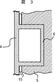
このように、重量構造物6は原子炉建屋1内の側壁4と一部を共有とする構造となっているが、ダイアフラムフロア5については共有せず、互いに独立の構造としてある。そのダイアフラムフロア5上面に滑り材としての金属板11,レール,コロ等のいずれか、あるいは組み合わせて設置し、その上にプール6が配置される。重量構造物6の自重については重量構造物6に接触するダイアフラムフロア5面と側壁4にて垂直荷重を受けるものとする。
As described above, the
ダイアフラムフロア5において、地震などで水平方向もしくは上下方向の荷重が加えられた場合や、圧力や熱等の影響によるダイアフラムフロア5の変形や伸縮が発生した場合、ダイアフラムフロア5面を共有した構造においては拘束条件が厳しいため、重量構造物6の支持部に過大な応力が発生する。しかし、実施例1においては、ダイアフラムフロア5の変形や伸縮が発生した場合、滑り材としての金属板11上で重量構造物6の底壁13が滑る事でダイアフラムフロア5面の変形や伸縮の自由度を確保し、その変形や伸縮を拘束する事による過大な応力の発生を抑制している。
When the
このようにダイアフラムフロア5と重量構造物6とが直接接続されていない独立した構造であるのでダイアフラムフロア5の変形や動きが重量構造物6によって拘束されず、過大な応力の発生がない。そのため、ダイアフラムフロア5や重量構造物6の破損が生じにくい安全な原子炉建屋1が提供できる。本実施例では、滑り材である金属板11をダイアフラムフロア5に固定設置したが、重量構造物6の底壁13の下面に固定設置してもよい。
Thus, since the
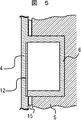
本発明の実施例2は、前述の実施例1にある構成を追加した構造の原子炉建屋1を提供せんとするものである。即ち、追加した構造とは、原子炉格納容器2の垂直な側壁4の重量構造物6に対面する部位に緩衝材として発泡金属の板を埋め込んである構造である。その他の構造は、先述の実施例1と同じであるので、説明を省略する。
The second embodiment of the present invention is intended to provide a
発泡金属として発泡アルミの板12を用いる。発泡アルミの板12にスタッドを接続し、そのスタッドと発泡アルミの板12とを側壁4のコンクリートを施工する際にそのコンクリートで埋設するようにして、発泡アルミの板12が重量構造物6側に薄いコンクリート層を介して対面するようにする。
A foamed
本実施例でも、水平方向もしくは上下方向の荷重が発生した場合、ダイアフラムフロア5と重量構造物6とが直接的には接続されること無く独立した構造であり、金属板11による滑り効果により重量構造物6が拘束されずダイアフラムフロア5に対して相対的に滑るため、互いに拘束しあって過大な応力を発生すると言う現象を低減することが可能である。
Also in this embodiment, when a load in the horizontal direction or the vertical direction is generated, the
側壁4については重量構造物6及び建屋からの荷重がかかった場合、側壁4と重量構造物6の共有部の強度が必要となるが、その荷重が発泡アルミの板12に伝達された際にかかる荷重を緩衝して低減することができる。
When the load from the
このように、実施例2においてもダイアフラムフロア5の変形や伸縮が発生した場合、実施例1と同様、滑り材の効果により重量構造物6がダイアフラムフロア5床面上を相対的にすべる事でそのダイアフラムフロア5の変形や伸縮の影響を逃がし、ダイアフラムフロア5と重量構造物6とに相互の拘束による過大な応力の発生を抑制している。
Thus, also in Example 2, when the deformation | transformation and expansion-contraction of the
重量構造物6が拘束されている側壁4の共有箇所について、ダイアフラムフロア5の変形や伸縮により重量構造物6が相対的にすべることで荷重がかかるが、緩衝材である発泡アルミの板12がその荷重を緩衝して低減することにより、重量構造物6と側壁4の共有箇所の応力を低減することが出来る。
A load is applied to the shared portion of the
本発明は、例えば、原子炉格納容器内のダイアフラムフロア上に重量構造物を設置する際に利用される。 The present invention is used, for example, when a heavy structure is installed on a diaphragm floor in a nuclear reactor containment vessel.
1…原子炉建屋、2…原子炉格納容器、3…原子炉圧力容器、4…側壁、5…ダイアフラムフロア、6…重量構造物、7…圧力抑制室、8…ドライウェル、9…冷却水、11…金属板、12…発泡アルミの板、13…底壁、14…支持ブラケット、15…シール。
DESCRIPTION OF
Claims (2)
前記原子炉格納容器内の圧力抑制室とドライウェルとの空間を区画するダイアフラムフロアと、A diaphragm floor that divides the space between the pressure suppression chamber and the dry well in the reactor containment vessel;
前記原子炉格納容器の側壁を一側壁として共有すると共に、底壁も前記原子炉格納容器に一体に接続されたプールとを備えた原子炉建屋であって、While sharing the side wall of the reactor containment vessel as one side wall, the bottom wall is a reactor building including a pool integrally connected to the reactor containment vessel,
前記ダイアフラムフロアは、前記プールの底面に対面する前記ダイアフラムフロアの上面に滑り材を備えることを特徴とする原子炉建屋。The nuclear reactor building according to claim 1, wherein the diaphragm floor includes a sliding material on an upper surface of the diaphragm floor facing a bottom surface of the pool.
前記原子炉格納容器の側壁のうち、前記プールに対面する部位に発泡金属を設置することを特徴とする原子炉建屋。A reactor building, wherein a foam metal is installed in a portion of the side wall of the reactor containment vessel facing the pool.
Priority Applications (1)
| Application Number | Priority Date | Filing Date | Title |
|---|---|---|---|
| JP2006142222A JP4671908B2 (en) | 2006-05-23 | 2006-05-23 | Building structure |
Applications Claiming Priority (1)
| Application Number | Priority Date | Filing Date | Title |
|---|---|---|---|
| JP2006142222A JP4671908B2 (en) | 2006-05-23 | 2006-05-23 | Building structure |
Publications (2)
| Publication Number | Publication Date |
|---|---|
| JP2007315755A JP2007315755A (en) | 2007-12-06 |
| JP4671908B2 true JP4671908B2 (en) | 2011-04-20 |
Family
ID=38849762
Family Applications (1)
| Application Number | Title | Priority Date | Filing Date |
|---|---|---|---|
| JP2006142222A Expired - Fee Related JP4671908B2 (en) | 2006-05-23 | 2006-05-23 | Building structure |
Country Status (1)
| Country | Link |
|---|---|
| JP (1) | JP4671908B2 (en) |
Family Cites Families (7)
| Publication number | Priority date | Publication date | Assignee | Title |
|---|---|---|---|---|
| JPS61226693A (en) * | 1985-03-30 | 1986-10-08 | 株式会社東芝 | Coupling device for diaphragm floor |
| JPH01132995A (en) * | 1987-11-19 | 1989-05-25 | Toshiba Corp | Building for nuclear power plant |
| JPH02195297A (en) * | 1989-01-25 | 1990-08-01 | Toshiba Corp | Earthquake-relief structure of building for nuclear power generation |
| JP2793437B2 (en) * | 1991-07-08 | 1998-09-03 | 株式会社東芝 | Reactor containment vessel |
| JPH08201564A (en) * | 1995-01-27 | 1996-08-09 | Toshiba Corp | Construction method of diaphragm floor in containment vessel |
| JPH0980184A (en) * | 1995-09-14 | 1997-03-28 | Hitachi Ltd | Primary containment vessel |
| JP2001208883A (en) * | 2000-01-28 | 2001-08-03 | Toshiba Corp | Reactor containment vessel |
-
2006
- 2006-05-23 JP JP2006142222A patent/JP4671908B2/en not_active Expired - Fee Related
Also Published As
| Publication number | Publication date |
|---|---|
| JP2007315755A (en) | 2007-12-06 |
Similar Documents
| Publication | Publication Date | Title |
|---|---|---|
| US11339849B2 (en) | Three-dimensional isolator with adaptive stiffness property | |
| US20120204509A1 (en) | Method and structure for damping movement in buildings | |
| JP2008121328A (en) | 3D seismic isolation device | |
| JP7044350B2 (en) | Anti-vibration floor structure | |
| JP6224926B2 (en) | Structure | |
| JP4671908B2 (en) | Building structure | |
| JP2007239306A (en) | Method of mounting base isolation damper | |
| JP5666807B2 (en) | 3D seismic isolation device | |
| JP2006328715A (en) | Floating floor vibration control structure | |
| JP2014101749A (en) | Period-prolonged architectural structure | |
| JP6379607B2 (en) | Damping building and building damping method | |
| JP2015094076A (en) | Vibration control structure | |
| JP4529564B2 (en) | Seismic structure of suspended ceiling | |
| JP7487041B2 (en) | Anti-vibration floor structure | |
| JP6628988B2 (en) | Seismic isolation device | |
| JPH10311162A (en) | Seismic isolated building | |
| KR102015561B1 (en) | Vibration control system for lateral force reduction of apartment building | |
| JP5100253B2 (en) | building | |
| JP2014105544A (en) | Vibration control structure | |
| JP2017043988A (en) | Vibration control building | |
| JP7712816B2 (en) | building | |
| JP7669260B2 (en) | Building structure with multiple column capitals | |
| JP2010203057A (en) | Structure for installing solar radiation utilization device for flat roof building | |
| JP6354125B2 (en) | Damping building and damping method | |
| JP6379608B2 (en) | Damping building and building damping method |
Legal Events
| Date | Code | Title | Description |
|---|---|---|---|
| A711 | Notification of change in applicant |
Free format text: JAPANESE INTERMEDIATE CODE: A712 Effective date: 20071122 |
|
| A621 | Written request for application examination |
Free format text: JAPANESE INTERMEDIATE CODE: A621 Effective date: 20080516 |
|
| A521 | Request for written amendment filed |
Free format text: JAPANESE INTERMEDIATE CODE: A523 Effective date: 20080516 |
|
| A977 | Report on retrieval |
Free format text: JAPANESE INTERMEDIATE CODE: A971007 Effective date: 20100104 |
|
| A131 | Notification of reasons for refusal |
Free format text: JAPANESE INTERMEDIATE CODE: A131 Effective date: 20100316 |
|
| A521 | Request for written amendment filed |
Free format text: JAPANESE INTERMEDIATE CODE: A523 Effective date: 20100517 |
|
| TRDD | Decision of grant or rejection written | ||
| A01 | Written decision to grant a patent or to grant a registration (utility model) |
Free format text: JAPANESE INTERMEDIATE CODE: A01 Effective date: 20110104 |
|
| A01 | Written decision to grant a patent or to grant a registration (utility model) |
Free format text: JAPANESE INTERMEDIATE CODE: A01 |
|
| A61 | First payment of annual fees (during grant procedure) |
Free format text: JAPANESE INTERMEDIATE CODE: A61 Effective date: 20110118 |
|
| R150 | Certificate of patent or registration of utility model |
Free format text: JAPANESE INTERMEDIATE CODE: R150 |
|
| FPAY | Renewal fee payment (event date is renewal date of database) |
Free format text: PAYMENT UNTIL: 20140128 Year of fee payment: 3 |
|
| LAPS | Cancellation because of no payment of annual fees |