JP2007239306A - Method of mounting base isolation damper - Google Patents
Method of mounting base isolation damper Download PDFInfo
- Publication number
- JP2007239306A JP2007239306A JP2006063306A JP2006063306A JP2007239306A JP 2007239306 A JP2007239306 A JP 2007239306A JP 2006063306 A JP2006063306 A JP 2006063306A JP 2006063306 A JP2006063306 A JP 2006063306A JP 2007239306 A JP2007239306 A JP 2007239306A
- Authority
- JP
- Japan
- Prior art keywords
- seismic isolation
- isolation damper
- bridge
- damper
- anchor
- Prior art date
- Legal status (The legal status is an assumption and is not a legal conclusion. Google has not performed a legal analysis and makes no representation as to the accuracy of the status listed.)
- Withdrawn
Links
Images


Abstract
Description
本発明は、橋脚、橋台等の下部構造物の上方に鉛直支承を介してプレストレストコンクリートからなる橋桁が配置された既設の橋梁に対して、新たに免震ダンパーを追加して取り付ける免震ダンパーの取付方法に関する。 The present invention provides a seismic isolation damper to which a new seismic isolation damper is additionally attached to an existing bridge in which a bridge girder made of prestressed concrete is arranged above a lower structure such as a pier and an abutment via a vertical support. It relates to the mounting method.
橋梁の支承構造については、阪神大震災規模の大地震に耐えられるようにするために、耐震構造を強化する必要があり、特に水平方向の免震性能を高めるために橋梁に緩衝装置や免震ダンパーを取り付けることが提案されている。橋梁が金属製の場合は、新設の橋梁に免震ダンパーを取り付けるうえでの問題は無く、既設の橋梁であっても、橋桁の下フランジへの穴あけと補強により免震ダンパーをボルト留めで取り付けることができる。一方、コンクリートに予め圧縮が加えられたプレストレストコンクリート(以下、PCと記す)からなる新設のPC橋の場合は、例えば特許文献1に示すように、弾性層の上下両端部に鋼製部材を有する免震ダンパーである水平力兼上揚力弾性抵抗装置が下部構造物の上部に下鋼製部材から延びたアンカーにより固定され、T型の上部構造物の間に埋め込まれるPCに上鋼製部材から延びたアンカーを固定することにより取り付けられた構造が知られている。
しかし、既設のT桁構造のPC橋に上記取り付け構造を適用すると、免震ダンパーをT桁間のPCへ取り付けのために、PCに長いアンカーを挿入する上向きの削孔を設けることが必要であるが、橋桁のPCと橋脚との間が狭い空間であるため、施工が非常に困難になっている。さらに、PC内に埋設されたケーブルや鉄筋に損傷を与えるとPCの強度が低下するため、ケーブル等を避けて削孔する必要があり施工がさらに困難になっている。また、既設の箱桁構造のPC橋では、例えば特許文献2に示すように、橋脚上方に配置した2つの箱桁間を連結部材で連結し、その橋軸直角方向両側にて各箱桁と橋脚間にそれぞれ荷重支持用弾性支承部材が設けられ、連結部材と橋脚間に免震ダンパーである緩衝部材が設けられたものがある。しかし、この支承構造は、2つの箱桁間を連結部材で連結するものであり、橋脚上部に箱桁間のスペースがある場合のみ有効である。よって、単独の箱桁の場合や2つ以上の箱桁であっても橋脚上にスペースがない場合は、この免震ダンパーの取付方法を適用することは困難である。
本発明は、上記問題を解決しようとするもので、プレストレストコンクリートからなるT桁,箱桁構造の既設の橋梁に対して、新たに免震ダンパーを簡易な工事により追加して取り付けることができる免震ダンパーの取付方法を提供することを目的とする。 The present invention is intended to solve the above-mentioned problem, and a seismic isolation damper can be newly attached to an existing bridge having a T-girder and box-girder structure made of prestressed concrete by simple construction. It aims at providing the installation method of a seismic damper.
上記目的を達成するために、本発明の構成上の特徴は、下部構造物の上方に鉛直支承を介してプレストレストコンクリートからなるT桁が配置された既設の橋梁に対して、新たに免震ダンパーを追加して取り付ける免震ダンパーの取付方法であって、下部構造物から橋軸方向に所定距離離れた位置にて、隣り合うT桁の立壁間を橋軸直角方向に連結する増打コンクリートを設け、免震ダンパーの上部をアンカーにより増打コンクリートに固定させ、下部構造物から増打コンクリートに対向して橋軸方向へ延出した延出部を設け、免震ダンパーの下部をアンカーにより延出部に固定させることにある。 In order to achieve the above object, the structural feature of the present invention is that a new seismic isolation damper is provided for an existing bridge in which a T girder made of prestressed concrete is disposed above a lower structure via a vertical bearing. The seismic isolation damper is attached by adding a concrete to add concrete to connect the vertical walls of adjacent T girders in a direction perpendicular to the bridge axis at a position a predetermined distance away from the lower structure in the bridge axis direction. The upper part of the seismic isolation damper is fixed to the increased concrete with an anchor, and an extension part extending in the bridge axis direction from the lower structure to the increased concrete is provided, and the lower part of the seismic isolation damper is extended with the anchor. It is to fix to the exit.
上記のように構成した本発明においては、下部構造物から橋軸方向に所定距離離れた位置にて、隣り合うT桁の立壁間を橋軸直角方向に連結する増打コンクリートを設け、下部構造物から増打コンクリートに対向して橋軸方向へ延出した延出部を設け、増打コンクリートと延出部間に免震ダンパーを取り付けることにより、大地震等の際に橋梁に加えられる大きな水平方向の震動を免震ダンパーによって減衰させることができる。これにより、免震ダンパーのT桁間への取り付けのために、プレストレストコンクリートに長いアンカーを挿入するための上向きの削孔を設ける必要がなく、また、下部構造物とT桁との間の狭い空間で取り付け作業を行う必要もない。その結果、本発明においては、下部構造物の上部に鉛直支承を介してプレストレストコンクリートからなるT桁が配置された既設の橋梁に対して、新たに免震ダンパーを簡易な方法で安価に追加して取り付けることができる。 In the present invention configured as described above, an additional concrete for connecting the vertical walls of adjacent T girders in a direction perpendicular to the bridge axis is provided at a position away from the lower structure by a predetermined distance in the bridge axis direction. A large extension added to the bridge in the event of a large earthquake, etc. by installing an extension part that extends in the direction of the bridge axis facing the reinforcement concrete from the object and installing a seismic isolation damper between the reinforcement concrete and the extension part Horizontal vibrations can be attenuated by seismic isolation dampers. Thereby, it is not necessary to provide an upward drilling hole for inserting a long anchor in the prestressed concrete for mounting the seismic isolation damper between the T girders, and a narrow space between the lower structure and the T girders. There is no need to perform installation work in space. As a result, in the present invention, a seismic isolation damper is newly added at a low cost by a simple method to an existing bridge in which a T-girder made of prestressed concrete is arranged on the upper part of the lower structure via a vertical support. Can be attached.
また、本発明の他の特徴は、下部構造物の上部に鉛直支承を介してプレストレストコンクリートからなる箱桁が配置された既設の橋梁に対して、新たに免震ダンパーを追加して取り付ける免震ダンパーの取付方法であって、下部構造物から橋軸方向に所定距離離れた位置にて、箱桁の底板部に貫通孔を形成すると共に、箱桁内の底板部上に取付板を載置し、免震ダンパーの上部に設けたアンカーを貫通孔に挿通して取付板に係止させることにより、免震ダンパーの上部をアンカーと取付板によって底板部を挟み込んで固定させ、下部構造物から橋軸方向へ延出した延出部を設け、免震ダンパーの下部をアンカーにより延出部に固定させることにある。 In addition, another feature of the present invention is that a seismic isolation damper is newly attached to an existing bridge in which box girders made of prestressed concrete are arranged on the upper part of a lower structure via a vertical support. A damper mounting method in which a through hole is formed in the bottom plate portion of the box girder at a predetermined distance from the lower structure in the bridge axis direction, and the mounting plate is placed on the bottom plate portion in the box girder The upper part of the seismic isolation damper is inserted into the through hole and locked to the mounting plate, and the upper part of the seismic isolation damper is fixed by sandwiching the bottom plate part between the anchor and the mounting plate. An extension part extending in the direction of the bridge axis is provided, and the lower part of the seismic isolation damper is fixed to the extension part by an anchor.
他の特徴においては、下部構造物から橋軸方向に所定距離離れた位置にて、箱桁の底板部と下部構造物から橋軸方向へ延出した延出部の間に免震ダンパーを取り付けることにより、大地震等の際に橋梁に加えられる大きな水平方向の震動を免震ダンパーによって減衰させることができる。これにより、免震ダンパーの箱桁への取り付けのために、上向きの削孔作業をする必要がなく、また、下部構造物と箱桁との間の狭い空間で取り付け作業を行う必要もない。その結果、他の特徴においては、下部構造物の上部に鉛直支承を介してプレストレストコンクリートからなる箱桁が配置された既設の橋梁に対して、新たに免震ダンパーを簡易な方法で安価に追加して取り付けることができる。 In another feature, the seismic isolation damper is attached between the bottom plate of the box girder and the extended portion extending from the lower structure in the bridge axis direction at a predetermined distance from the lower structure in the bridge axis direction. Thus, the large horizontal vibration applied to the bridge in the event of a large earthquake or the like can be attenuated by the seismic isolation damper. Accordingly, it is not necessary to perform an upward drilling operation for mounting the seismic isolation damper to the box girder, and it is not necessary to perform the mounting operation in a narrow space between the lower structure and the box girder. As a result, in other features, new seismic isolation dampers were added in a simple and inexpensive way to existing bridges with pre-stressed concrete box girders placed on top of the substructure via vertical bearings. Can be attached.
また、本発明において、免震ダンパーが、既設の鉛直支承より大きな上下変位吸収機構を有することが好ましい。免震ダンパーの上下変位吸収機構としては、免震ダンパー自体の鉛直方向の圧縮バネをやわらかくしたり、上部構造物の変位が免震ダンパーに伝わらないように上部構造物と免震ダンパーの間に隙間を設けた構造にすること等がある。これにより、免震ダンパーが既設の鉛直支承に対して橋軸方向に位置がずれているために、橋桁の回転変位時に免震ダンパーへ大きな沈み込みの変位が発生しても、免震ダンパーが上下変位吸収機構を有することにより、既設の鉛直支承より大きな上下変位吸収が可能になり、その結果、延出部に余分な鉛直荷重が加わることがなく延出部の耐久性が確保されると共に、免震ダンパーの減衰機能に悪影響を与えない。 In the present invention, it is preferable that the seismic isolation damper has a vertical displacement absorbing mechanism larger than the existing vertical bearing. As the vertical displacement absorption mechanism of the seismic isolation damper, the vertical compression spring of the seismic isolation damper itself is softened, or the displacement of the upper structure is not transmitted to the seismic isolation damper between the upper structure and the seismic isolation damper. For example, a structure with a gap may be provided. As a result, the seismic isolation damper is displaced in the direction of the bridge axis with respect to the existing vertical bearing. By having an up / down displacement absorbing mechanism, it is possible to absorb up / down displacement larger than the existing vertical bearing, and as a result, no extra vertical load is applied to the extended portion, and the durability of the extended portion is ensured. Does not adversely affect the damping function of the seismic isolation damper.
また、本発明のその他の特徴は、下部構造物の上方に鉛直支承を介してプレストレストコンクリートからなる橋桁が配置された既設の橋梁に対して、新たに免震ダンパーを追加して取り付ける免震ダンパーの取付方法であって、免震ダンパーの一方の取付面を、下部構造物から橋軸方向に所定距離離れた位置にてアンカーにより橋桁の立壁に固定させ、下部構造物から橋軸方向へ延出した延出部を設け、免震ダンパーの他方の取付面をアンカーにより延出部に固定させることにある。 In addition, another feature of the present invention is that a seismic isolation damper is newly attached to an existing bridge in which a bridge girder made of prestressed concrete is disposed above a lower structure via a vertical support. The one mounting surface of the seismic isolation damper is fixed to the vertical wall of the bridge girder by an anchor at a position away from the lower structure in the bridge axis direction, and extends from the lower structure in the bridge axis direction. The extended part is provided, and the other mounting surface of the seismic isolation damper is fixed to the extended part by an anchor.
その他の特徴においては、下部構造物から橋軸方向に所定距離離れた位置にて、橋桁の立壁と下部構造物から橋軸方向へ延出した延出部に免震ダンパーの両取付面を固定して取り付けることにより、大地震等の際に橋梁に加えられる大きな水平方向の震動を免震ダンパーによって減衰させることができる。また、免震ダンパーが水平ではなく縦に配置されるため、既設の鉛直支承よりも大きな上下変位が加わっても、免震ダンパーに引張りや圧縮の力が加わらずせん断変形で対応できるため、免震ダンパーの機能や延出部の耐久性が確保される。また、本発明においては、T桁や箱桁の立壁を利用できるので、増打コンクリートや桁への穴あけ等の作業が不要になり取り付けの手間が抑えられ、既設の橋梁に対して、新たに免震ダンパーを簡易な方法で安価に追加して取り付けることができる。 In other features, the seismic isolation damper mounting surfaces are fixed to the standing wall of the bridge girder and the extension extending from the lower structure to the bridge axis direction at a predetermined distance from the lower structure in the bridge axis direction. As a result, the large horizontal vibration applied to the bridge in the event of a large earthquake or the like can be attenuated by the seismic isolation damper. In addition, since the seismic isolation dampers are arranged vertically rather than horizontally, even if a larger vertical displacement than the existing vertical bearing is applied, the seismic isolation dampers can be accommodated by shear deformation without applying tensile or compressive force. The function of the seismic damper and the durability of the extension are ensured. In addition, in the present invention, since a standing wall of a T girder or a box girder can be used, work such as perforating concrete or drilling in the girder is not required, and installation work can be reduced. A seismic isolation damper can be added and attached at low cost by a simple method.
また、その他の特徴において、免震ダンパーが、圧縮された状態で取り付けられることが好ましい。免震ダンパーが、縦方向に配置されることにより、軸直直角方向に変位が加わった際に引っ張り荷重を受ける可能性があるが、免震ダンパーが圧縮した状態で取り付けられるため、橋軸直角方向の変位にも免震ダンパーの圧縮代の範囲で対応できて弾性体に引っ張り力が加わらない。そのため、免震ダンパーの引っ張り荷重に対する耐久性が確保される。 In another aspect, the seismic isolation damper is preferably attached in a compressed state. When the seismic isolation damper is placed in the vertical direction, there is a possibility of receiving a tensile load when displacement is applied in the direction perpendicular to the axis, but since the seismic isolation damper is mounted in a compressed state, it is perpendicular to the bridge axis. The displacement in the direction can be handled within the range of the compression allowance of the seismic isolation damper, and no tensile force is applied to the elastic body. Therefore, durability against the tensile load of the seismic isolation damper is ensured.
本発明においては、下部構造物の上部に鉛直支承を介してプレストレストコンクリートからなるT桁や箱桁が配置された既設の橋梁に対して、新たに免震ダンパーを簡易な方法で追加して取り付けることができ、既存の橋梁で大震災の際の大きな水平力に対応できるので、橋梁を安価に維持できると共に大地震の際の既設橋梁の安全性に対する不安が解消される。 In the present invention, a seismic isolation damper is newly added and attached to an existing bridge in which a T-girder or box girder made of prestressed concrete is arranged on the upper part of the lower structure via a vertical support. The existing bridge can cope with a large horizontal force in the event of a major earthquake, so that the bridge can be maintained at a low cost and the anxiety about the safety of existing bridges in the event of a major earthquake is eliminated.
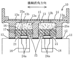
以下、本発明の一実施例について図面を用いて説明する。図1,図2は、実施例1に係るプレストレストコンクリート(以下、PCと記す)からなるT桁が配置された既設の橋梁への免震ダンパー取り付け部分を一部破断正面図及び一部破断側面図により示したものである。橋梁10は、下部構造物である橋脚11の上方に上下方向の荷重を支承する鉛直支承12を介してPCからなる橋軸直角断面がT字状のT桁13が配置されており、橋脚11から橋軸方向に所定距離離れた位置にてT桁13に設けた増打コンクリート16と橋脚11に設けた延出部18間に水平方向の震動を減衰させる厚板状の免震ダンパー21が水平に設置されている。T桁13は、T字状の単位桁13aが橋軸方向を揃えて連結部13bを介して3つ並列に繋げられており、その上面に載置された橋梁の床版14を支持している。また、橋脚11上において各単位桁13aの間は、上部から下部近傍位置までPCで埋められたコンクリート部15となっている。各単位桁13aの下端と橋脚11間には、橋軸方向の両端側に各1個の鉛直支承12が介在している。
Hereinafter, an embodiment of the present invention will be described with reference to the drawings. 1 and 2 are a partially broken front view and a partially broken side view of a part where a seismic isolation damper is attached to an existing bridge where a T-girder made of prestressed concrete (hereinafter referred to as PC) according to Example 1 is arranged. This is shown in the figure. The
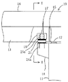
橋脚11から橋軸方向に所定距離離れた位置において、隣り合う単位T桁13aの立壁間が橋軸直角方向に増打コンクリート16によって連結されており、増打コンクリート16内には補強筋17が埋設されている。また、橋脚11の橋軸方向側面には、鉄筋コンクリート製の立体形状の延出部18が取り付けられて増打コンクリート16に対向して延出している。免震ダンパー21は、図3に示すように、鋼製の上下補強板22a,22bに挟まれたゴム弾性体層22c中に複数の鋼製の補強板22dが互いに水平に所定間隔を隔てて埋設されたゴム支承体22と、上補強板22a上面にボルトで固定された中間板23とその上に重ね合わされた上沓29と、下補強板22bの下面にボルトで固定された下沓26を設けている。中間板23は、橋軸方向両側がゴム支承体22からわずかに外方に突出しており、上沓29及び下沓26は、橋軸方向両側が中間板23よりさらに橋軸方向の外方に延びている。下沓26は下取付板24上にボルトで固定されている。下取付板24は下面に取り付けられたアンカー24aを上記延出部18に埋設させることにより延出部18に固定されている。
At a position away from the
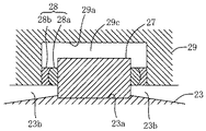
中間板23は、上面が橋軸方向中央位置から両側に向けて下方にわずかに傾斜しており、上面中央位置に円形の嵌合孔23aを設けており、嵌合孔23aにはせん断キー27が嵌合されている。上沓29の平坦な下面の橋軸方向中央には嵌合孔23aに対応して嵌合孔23aより径の大きい円形の嵌合孔29aを設けており、嵌合孔23aから突出したせん断キー27が嵌合孔29aに嵌合されている。せん断キー27と嵌合孔29aの内周との間には環状の軸受部28が挿嵌されている。軸受部28は、図4に示すように、互いに回転方向に摺動可能な内輪部28aと外輪部28bとにより構成されており、内輪部28a内周面とせん断キー27は鉛直方向に対して摺動可能に嵌合している。上沓29の軸方向両端の下面には、ストッパ部29bがボルトにより固定されて中間板23側面との間にわずかの隙間を設けている。上沓29は、上取付板25にボルトで固定されており、上取付板25に取り付けられたアンカー25aを上記増打コンクリート16に埋設させることにより増打コンクリート16に固定される。
The
免震ダンパー21は、図4に示すように、延出部18側のせん断キー27と、T桁13に一体で設けた増内コンクリート16側の軸受部28とが摺動可能に嵌合されており、せん断キー27の上面と嵌合孔29aの底面、軸受部28や上沓29の下面と中間板23の上面との間にそれぞれ隙間29c,23bを設けている。そのため、上取付板23が上下変位を吸収する際に、せん断キー27と軸受部28の内輪部28a内周面との相互の摺動によって上沓29すなわちT桁13の上下変位が可能になり、その結果、上沓29の上下変位が吸収されてゴム支承体22に作用しないので、延出部18に余分な鉛直荷重がかからないようにされる。ただし、免震ダンパー21の構造については、これに限らず、同様の上下変位吸収機構を備えた構造のものであってもよい。
As shown in FIG. 4, the
上記のように構成した実施例1においては、橋脚11から橋軸方向に所定距離離れた位置にて、免震ダンパー21が、隣り合うT桁13aの立壁間を橋軸直角方向に連結する増打コンクリート16と橋脚11から増打コンクリート16に対向して橋軸方向へ延出した延出部18との間に取り付けられることにより、大地震等の際に橋梁10に加えられる大きな水平方向の震動を免震ダンパー21によって減衰させることができる。そのため、実施例1においては、免震ダンパー21をT桁13間のPC製のコンクリート部15へ取り付ける必要がないので、コンクリート部15に長いアンカーを挿入するための上向きの削孔を設ける必要がなく、また、T桁13間のコンクリート部15と橋脚11との間の狭い空間で取り付け作業を行う必要もない。そのため、橋脚11の上部に鉛直支承12を介してPCからなるT桁13が配置された既設の橋梁10に対して、新たに免震ダンパー21を簡易な方法で安価に追加して取り付けることができる。
In the first embodiment configured as described above, the
その結果、実施例1においては、既存の橋梁10で大震災に対応できるので、橋梁10を安価に維持できると共に大地震の際の既設橋梁の安全性に対する不安が解消される。また、免震ダンパー21は、既設の鉛直支承12に対して橋軸方向に位置がずれており大きな上下変位吸収が必要になる。しかし、免震ダンパー21は、上記上下変位吸収機構を設けているため、既設の鉛直支承12より大きな上下変位吸収が可能であり、そのため、免震ダンパー21の機能が阻害されることなく、延出部18の耐久性が維持される。
As a result, in the first embodiment, the existing
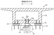
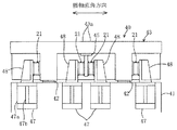
つぎに、実施例2について図面を用いて説明する。図5,図6は、実施例2に係るPCからなる箱桁が配置された既設の橋梁への免震ダンパー取り付け部分を一部破断正面図及び一部破断側面図により示したものである。橋梁30は、下部構造物である橋脚31の上方に上下方向の変位を支承する鉛直支承32を介してプレストレストコンクリートからなる橋軸直角断面が中空の長方形枠状の箱桁33が配置されており、橋脚31から橋軸方向に所定距離離れた位置にて箱桁33の底板部34と橋脚31に取り付けた延出部36間に水平方向の震動を減衰させる上記免震ダンパー21が水平状態で設置されている。箱桁33の底板部34と橋脚31間には、橋軸直角方向両端にそれぞれ1つの鉛直支承32が介在している。
Next, Example 2 will be described with reference to the drawings. FIGS. 5 and 6 are a partially broken front view and a partially broken side view of a seismic isolation damper mounting portion on an existing bridge on which box girders made of PC according to the second embodiment are arranged. The
橋脚11から橋軸方向に所定距離離れた位置において、箱桁33内の底板部34に貫通孔34aが形成されており、底板部34上の貫通孔34a位置に合わせて取付板35が載置されている。また、橋脚31の橋軸方向側面にアンカー36aにより取り付けられて延出した鋼製の延出部36が取付板35位置に対向して設けられている。免震ダンパー21は、延出部36と底板部34間に配置されてアンカーであるボルト24aにより延出部36に固定される。また、免震ダンパー21の上取付板25に取り付けられたアンカー25aが箱桁33内の底板部34に形成された貫通孔34aに挿入され、アンカー25aが取付板35にねじ止め等によって係止される。これにより、免震ダンパー21の上部が、アンカー25aと取付板35により底板部34を挟み込んで底板部34に固定される。
A through
上記のように構成した実施例2においては、橋脚31から橋軸方向に所定距離離れた位置にて、箱桁33の底板部34と橋脚31から橋軸方向へ延出した延出部36の間に免震ダンパー21を取り付けることにより、大地震等の際に橋梁に加えられる大きな水平方向の震動を免震ダンパー21によって減衰させることができる。これにより、箱桁33の空間内で作業ができるため、免震ダンパー21の箱桁33への取り付けのために、上向きの削孔作業をする必要がなく、また、橋脚31と箱桁33との間の狭い空間で取り付け作業を行う必要もない。そのため、実施例2においては、橋脚31上方に鉛直支承32を介してPCからなる箱桁33が配置された既設の橋梁30に対して、新たに免震ダンパー21を簡易な方法で安価に追加して取り付けることができる。その結果、実施例2においても上記実施例1と同様に、既存の橋梁30で大震災に対応できるので、橋梁を安価に維持できると共に大地震の際の既設橋梁の安全性に対する不安が解消される。また、免震ダンパー21は、せん断キー27の上面と嵌合孔29aの底面、軸受部28や上沓29の下面と中間板23の上面との間にそれぞれ隙間を設けており、既設の鉛直支承12に対して橋軸方向に位置がずれていることによる大きな上下変位を吸収できるため、免震ダンパー21の機能が阻害されることなく、延出部18の耐久性が維持される。
In the second embodiment configured as described above, the
なお、実施例1,2においては、せん断キー27の上面と嵌合孔29aの底面、軸受部28や上沓29の下面と中間板23の上面との間にそれぞれ隙間を設けた免震ダンパー21により、既設の鉛直支承12に対して橋軸方向に位置がずれていることによる大きな上下変位を吸収しているがこれに限らない。免震ダンパーとして、単にゴム支承体22を上下の取付板で挟んだ構造とし、ゴム支承体22の圧縮方向のバネをやわらかくすることにより、免震ダンパーは橋桁の上下変位を十分に吸収することができる。
In the first and second embodiments, the seismic isolation damper is provided with a gap between the upper surface of the
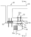
つぎに、実施例3について説明する。図7,図8は、実施例3に係るPCからなるT桁が配置された既設の橋梁への免震ダンパー取り付け部分を一部破断正面図及び一部破断側面図により示したものである。実施例3においては、橋梁40は、下部構造物である橋脚41の上方に上下方向の変位を支承する鉛直支承42を介してPCからなる橋軸直角断面がT字状のT桁43が配置されており、橋脚41から橋軸方向に所定距離離れた位置にて橋脚41に取り付けられた上下延出部47,48とT桁43立壁との間に水平方向の震動を減衰させる免震ダンパー21が水平ではなく縦にかつ橋軸直角方向を向いて4個設置されている。また、実施例3の免震ダンパー21においては、実施例1,2のようなせん断キーや中間板及び軸受部を有する複雑な構造ではなく、ゴム支承体22を両取付板24,25を挟んだ単純な構造を採用している。
Next, Example 3 will be described. 7 and 8 show a part of the seismic isolation damper attached to the existing bridge on which the T-girder made of PC according to Example 3 is arranged, with a partially broken front view and a partially broken side view. In the third embodiment, the
橋脚41から橋軸方向に所定距離離れた位置において、隣り合う単位T桁43aの橋軸直角方向中間位置にて天井壁に取り付けられて垂下するT桁43の一部として機能するT字状のブラケット45が設けられている。また、橋脚41側面には、2つの単位T桁43aを挟んだ両側に4個の鋼製の下延出部47が取り付けられており、各下延出部47にボルト等により固定されて上部に一体で延びた上延出部48が設けられて上下延出部47,48により延出部を構成している。下延出部47は、直角に曲げられたくの字状の基部47aと、基部47aのくの字の内側を補強するリブ47bとを設けている。上延出部48も下延出部47と同様の構造で、下延出部47に対して90°回転して配置されている。
At a position away from the
T桁43の橋軸直角方向の両外側に配置された免震ダンパー21については、上取付板23がT桁43の立壁にアンカー(図示しない)により固定され、下取付板24が上延出部48にアンカー(図示しない)により固定される。また、T桁43の間に配置された一対の免震ダンパー21については、上取付板23が、ブラケット45の立壁にアンカー(図示しない)により固定され、下取付板24が上延出部48にアンカー(図示しない)により固定される。ここで、各免震ダンパー21は、ゴム支承体22が上下取付板24,25間で圧縮力を受けた状態で橋軸直角方向を向いて取り付けられる。なお、上下取付板24,25の取り付けについは、上記と逆であってもよい。
With respect to the
上記のように構成した実施例3においては、橋脚41から橋軸方向に所定距離離れた位置にて、T桁43の立壁及びブラケット45の立壁と橋脚41から橋軸方向へ延出した上下延出部47,48に免震ダンパー21の上下取付板24,25を固定して取り付けることにより、大地震等の際に橋梁に加えられる大きな水平方向の震動を免震ダンパー21によって減衰させることができる。また、免震ダンパー21が縦にかつ橋軸直角方向を向いて配置されるため、既設の鉛直支承42よりも大きな上下変位が加わっても、引張りや圧縮の力が加わらずせん断変形で対応できる。そのため、免震ダンパー21の機能を損なうことなく、さらに延出部47が取り付けられる橋脚41側面の耐久性が確保される。
In the third embodiment configured as described above, the vertical wall extending in the bridge axis direction from the standing wall of the
さらに、実施例3においては、T桁43あるいはそれに取り付けられたブラケット45の立壁を利用できるので、増打コンクリートや桁への穴あけ等の作業が不要になり取り付けの手間が抑えられる。その結果、実施例3においても上記実施例1と同様に、既存の橋梁40で大震災に対応できるので、橋梁を安価に維持できると共に大地震の際の既設橋梁の安全性に対する不安が解消される。また、実施例3では、免震ダンパー21が、縦方向にかつ橋軸直角方向に配置されるため、軸直直角方向に変位が加わった際に、引っ張り加重を受ける可能があるが、免震ダンパー21が圧縮した状態で取り付けられるため、橋軸直角方向の変位にも圧縮代の範囲で対応でき、引っ張り力が加わらないので、免震ダンパー21の耐久性が損なわれない。
Furthermore, in the third embodiment, since the standing wall of the T-
つぎに、実施例4について図面を用いて説明する。図9,図10は、実施例4に係るPCからなる箱桁が配置された既設の橋梁への免震ダンパー取り付け部分を一部破断正面図及び一部破断側面図により示したものである。実施例4は、実施例2に示した橋梁30は橋脚31から橋軸方向に所定距離離れた位置にて、箱桁33の底板部34と橋脚31取り付けられた延出部36間に免震ダンパー21を水平状態で設置する代わりに、箱桁33の立壁38と橋脚31に取り付けられた延出部であるブラケット51間に免震ダンパー21を縦にすると共に橋軸直角方向に向けて設置するようにしたものである。橋梁のその他の部分については実施例2に示したものと同様である。また、実施例4の免震ダンパー21においては、実施例3と同様に、ゴム支承体22を両取付板24,25を挟んだ単純な構造を採用している。
Next, Example 4 will be described with reference to the drawings. FIGS. 9 and 10 show a part of a base isolation damper attached to an existing bridge on which a box girder made of PC according to Example 4 is arranged, with a partially broken front view and a partially broken side view. In the fourth embodiment, the
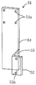
ブラケット51は、図11に示すように、鋼製厚板を加工して形成されたもので、長方形の橋脚取付部52と、橋脚取付部52に対して直角に曲げられた長方形の連結部53と、連結部53に対して直角に曲げ返された長方形で連結部53に対して片方に延びたダンパー取付部54とを有している。ブラケット51は、橋脚取付部52にて橋脚31の橋軸直角方向の側面に連結部53を外方に向けてアンカー52aにより固定され、ダンパー取付部54が橋軸方向に所定距離延びた状態に配置される。これにより、ダンパー取付部54が橋軸方向に延びた箱桁33の立壁38と対向するようになる。図10に示すように、立壁38には取付孔39が設けられており、免震ダンパー21が取付孔39にアンカー25aにより取り付けられる。ダンパー取付部54と箱桁33の立壁38間において、免震ダンパー21の上取付板25が、箱桁33の立壁38にアンカー25aにより固定され、下取付板24がダンパー取付部54にアンカー24aにより固定される。ここで、免震ダンパー21は、ゴム支承体22が両取付板24,25間で圧縮力を受けた状態でT桁43とダンパー取付部54に取り付けられている。なお、上下取付板24,25の取り付けについは、上記と逆であってもよい。
As shown in FIG. 11, the
上記のように構成した実施例4においては、橋脚31から橋軸方向に所定距離離れた位置にて、箱桁33の立壁38と橋脚31から橋軸方向へ延出したブラケット51に免震ダンパー21の上下取付板24,25を固定して取り付けることにより、大地震等の際に橋梁に加えられる大きな水平方向の震動を免震ダンパー21によって減衰させることができる。そして、免震ダンパー21が縦にかつ橋軸直角方向に配置されるため、既設の鉛直支承12よりも大きな上下変位が加わっても、引張りや圧縮の力が加わらずせん断変形で対応できる。そのため、免震ダンパー21の機能を損なうことなく、さらにブラケット51が取り付けられる橋脚31側面の耐久性が損なわれない。
In the fourth embodiment configured as described above, the seismic isolation damper is provided on the standing
また、本実施例においては、免震ダンパー21の取り付けに箱桁33の立壁38を利用できるので、増打コンクリートや桁への穴あけ等の作業が不要になり取り付けの手間が抑えられる。その結果、実施例4においても上記実施例1と同様に、既存の橋梁40で大震災に対応できるので、橋梁を安価に維持できると共に大地震の際の既設橋梁の安全性に対する不安が解消される。また、実施例4では、免震ダンパー21が、縦方向に配置されるため、軸直直角方向に変位が加わった際に、引っ張り加重を受ける可能があるが、免震ダンパー21が圧縮した状態で取り付けられるため、橋軸直角方向の変位にも圧縮代の範囲で対応でき、引っ張り力が加わらないので、免震ダンパー21の耐久性が損なわれない。
Further, in the present embodiment, since the standing
なお、上記各実施例に示した免震ダンパーについては、一例であり、本発明の主旨を逸脱しない範囲において、種々の形態で実施することができる。 In addition, about the seismic isolation damper shown to said each Example, it is an example and can be implemented with a various form in the range which does not deviate from the main point of this invention.
本発明は、下部構造物の上部に鉛直支承を介してプレストレストコンクリートからなるT桁や箱桁が配置された既設の橋梁に対して、新たに免震ダンパーを簡易な方法で追加して取り付けることができ、既存の橋梁で大震災に対応できるので、橋梁を安価に維持できて経済的であると共に既設の橋梁において大地震に対する社会的な不安が払拭される効果が得られるので、有用である。 The present invention attaches a new seismic isolation damper in a simple manner to an existing bridge in which a T-spar or box girder made of prestressed concrete is arranged on the upper part of the substructure via a vertical support. Since existing bridges can cope with a major earthquake disaster, it is economical because it can maintain the bridges at a low cost and is effective in eliminating social anxiety about large earthquakes in existing bridges.
10…橋梁、11…橋脚、12…鉛直支承、13…T桁、16…増打コンクリート、18…延出部、21…免震ダンパー、24…下取付板、25…上取付板、27…せん断キー、28…軸受部、30…橋梁、31…橋脚、32…鉛直支承、33…箱桁、34…底板部、35…取付板、36…延出部、38…立壁、39…取付孔、40…橋梁、41…橋脚、42…鉛直支承、43…T桁、45…ブラケット、47…下延出部、48…上延出部、51…ブラケット。
DESCRIPTION OF
Claims (5)
前記下部構造物から橋軸方向に所定距離離れた位置にて、隣り合う前記T桁の立壁間を橋軸直角方向に連結する増打コンクリートを設け、前記免震ダンパーの上部をアンカーにより該増打コンクリートに固定させ、
前記下部構造物から前記増打コンクリートに対向して橋軸方向へ延出した延出部を設け、前記免震ダンパーの下部をアンカーにより該延出部に固定させることを特徴とする免震ダンパーの取付方法。 A method of attaching a seismic isolation damper to a newly installed seismic isolation damper to an existing bridge in which a T-girder made of prestressed concrete is arranged via a vertical support above the substructure,
At the position separated from the lower structure by a predetermined distance in the bridge axis direction, an increased concrete is provided to connect the adjacent standing walls of the T girders in the direction perpendicular to the bridge axis, and the upper part of the seismic isolation damper is increased by the anchor. Fixed to the concrete,
An extension part extending in the direction of the bridge axis from the lower structure facing the increased concrete is provided, and the lower part of the base isolation damper is fixed to the extension part by an anchor. Mounting method.
前記下部構造物から橋軸方向に所定距離離れた位置にて、前記箱桁の底板部に貫通孔を形成すると共に、該箱桁内の底板部上に取付板を載置し、前記免震ダンパーの上部に設けたアンカーを該貫通孔に挿通して該取付板に係止させることにより、該免震ダンパーの上部を該アンカーと該取付板によって該底板部を挟み込んで固定させ、
前記下部構造物から橋軸方向へ延出した延出部を設け、前記免震ダンパーの下部をアンカーにより該延出部に固定させることを特徴とする免震ダンパーの取付方法。 A method of attaching a seismic isolation damper to an existing bridge in which a box girder made of prestressed concrete is arranged via a vertical support on the upper part of the substructure.
A through hole is formed in the bottom plate portion of the box girder at a position away from the lower structure in the bridge axis direction, and a mounting plate is placed on the bottom plate portion in the box girder, and the seismic isolation By inserting the anchor provided on the upper part of the damper into the through hole and locking it to the mounting plate, the upper part of the seismic isolation damper is sandwiched and fixed by the anchor and the mounting plate,
A method of attaching a seismic isolation damper, comprising: an extension portion extending from the lower structure in a bridge axis direction, and fixing a lower portion of the seismic isolation damper to the extension portion by an anchor.
前記免震ダンパーの一方の取付面を、前記下部構造物から橋軸方向に所定距離離れた位置にてアンカーにより該橋桁の立壁に固定させ、
前記下部構造物から橋軸方向へ延出した延出部を設け、前記免震ダンパーの他方の取付面をアンカーにより該延出部に固定させることを特徴とする免震ダンパーの取付方法。 A method of attaching a seismic isolation damper to a newly installed seismic isolation damper to an existing bridge where a bridge girder made of prestressed concrete is arranged via a vertical support above the substructure,
One mounting surface of the seismic isolation damper is fixed to the standing wall of the bridge girder by an anchor at a position away from the lower structure in the bridge axis direction by a predetermined distance,
A method for attaching a seismic isolation damper, comprising: an extension part extending in a bridge axis direction from the lower structure; and fixing the other attachment surface of the seismic isolation damper to the extension part with an anchor.
Priority Applications (1)
| Application Number | Priority Date | Filing Date | Title |
|---|---|---|---|
| JP2006063306A JP2007239306A (en) | 2006-03-08 | 2006-03-08 | Method of mounting base isolation damper |
Applications Claiming Priority (1)
| Application Number | Priority Date | Filing Date | Title |
|---|---|---|---|
| JP2006063306A JP2007239306A (en) | 2006-03-08 | 2006-03-08 | Method of mounting base isolation damper |
Publications (1)
| Publication Number | Publication Date |
|---|---|
| JP2007239306A true JP2007239306A (en) | 2007-09-20 |
Family
ID=38585108
Family Applications (1)
| Application Number | Title | Priority Date | Filing Date |
|---|---|---|---|
| JP2006063306A Withdrawn JP2007239306A (en) | 2006-03-08 | 2006-03-08 | Method of mounting base isolation damper |
Country Status (1)
| Country | Link |
|---|---|
| JP (1) | JP2007239306A (en) |
Cited By (10)
| Publication number | Priority date | Publication date | Assignee | Title |
|---|---|---|---|---|
| JP2008038504A (en) * | 2006-08-08 | 2008-02-21 | Tokyo Fabric Kogyo Kk | Method for improving antiseismic performance of bridge |
| CN102022001A (en) * | 2010-12-28 | 2011-04-20 | 北京中铁房山桥梁有限公司 | Integrated binding and locating device of single-box double-chamber full span box girder reinforcing steel bar |
| ES2372095A1 (en) * | 2008-04-30 | 2012-01-16 | Universidad De Granada | Bridge reconditioning system through passive dissipation elements. (Machine-translation by Google Translate, not legally binding) |
| CN101824799B (en) * | 2010-02-09 | 2012-07-04 | 衡水橡胶股份有限公司 | Construction method for transverse connection of T-shaped concrete simply supported combined bridge |
| JP2012255330A (en) * | 2011-05-18 | 2012-12-27 | Chubu Electric Power Co Inc | Damper to be rigid-frame in earthquake, earthquake resistance improving construction method of dam sluice gate piers and earthquake resistance improving construction method of bridge |
| JP2014034853A (en) * | 2012-08-10 | 2014-02-24 | Sumitomo Rubber Ind Ltd | Bridge and vibration control damper for bridge |
| JP2016075120A (en) * | 2014-10-09 | 2016-05-12 | 公益財団法人鉄道総合技術研究所 | Bridge fall prevention method for existing bridge girder exposed to seismic and tsunami force |
| CN108978446A (en) * | 2018-09-28 | 2018-12-11 | 武汉理工大学 | A kind of Self-resetting energy-dissipation structure suitable for bridge |
| JP2018204419A (en) * | 2017-01-25 | 2018-12-27 | オリエンタル白石株式会社 | Bearing replacement method for existing concrete beam |
| JP7278554B1 (en) | 2022-02-17 | 2023-05-22 | 大成建設株式会社 | Horizontal force sharing structure installation frame, horizontal force sharing structure installation device, and horizontal force sharing structure installation method |
-
2006
- 2006-03-08 JP JP2006063306A patent/JP2007239306A/en not_active Withdrawn
Cited By (13)
| Publication number | Priority date | Publication date | Assignee | Title |
|---|---|---|---|---|
| JP2008038504A (en) * | 2006-08-08 | 2008-02-21 | Tokyo Fabric Kogyo Kk | Method for improving antiseismic performance of bridge |
| ES2372095A1 (en) * | 2008-04-30 | 2012-01-16 | Universidad De Granada | Bridge reconditioning system through passive dissipation elements. (Machine-translation by Google Translate, not legally binding) |
| CN101824799B (en) * | 2010-02-09 | 2012-07-04 | 衡水橡胶股份有限公司 | Construction method for transverse connection of T-shaped concrete simply supported combined bridge |
| CN102022001A (en) * | 2010-12-28 | 2011-04-20 | 北京中铁房山桥梁有限公司 | Integrated binding and locating device of single-box double-chamber full span box girder reinforcing steel bar |
| JP2012255330A (en) * | 2011-05-18 | 2012-12-27 | Chubu Electric Power Co Inc | Damper to be rigid-frame in earthquake, earthquake resistance improving construction method of dam sluice gate piers and earthquake resistance improving construction method of bridge |
| JP2014034853A (en) * | 2012-08-10 | 2014-02-24 | Sumitomo Rubber Ind Ltd | Bridge and vibration control damper for bridge |
| JP2016075120A (en) * | 2014-10-09 | 2016-05-12 | 公益財団法人鉄道総合技術研究所 | Bridge fall prevention method for existing bridge girder exposed to seismic and tsunami force |
| JP2018204419A (en) * | 2017-01-25 | 2018-12-27 | オリエンタル白石株式会社 | Bearing replacement method for existing concrete beam |
| JP6995584B2 (en) | 2017-01-25 | 2022-01-14 | オリエンタル白石株式会社 | Bearing replacement method for existing concrete girders |
| CN108978446A (en) * | 2018-09-28 | 2018-12-11 | 武汉理工大学 | A kind of Self-resetting energy-dissipation structure suitable for bridge |
| CN108978446B (en) * | 2018-09-28 | 2024-04-12 | 武汉理工大学 | Self-resetting energy consumption structure suitable for bridge |
| JP7278554B1 (en) | 2022-02-17 | 2023-05-22 | 大成建設株式会社 | Horizontal force sharing structure installation frame, horizontal force sharing structure installation device, and horizontal force sharing structure installation method |
| JP2023119783A (en) * | 2022-02-17 | 2023-08-29 | 大成建設株式会社 | Horizontal force distribution structure installation trestle, horizontal force distribution structure installation device, and horizontal force distribution structure installation method |
Similar Documents
| Publication | Publication Date | Title |
|---|---|---|
| JP2007239306A (en) | Method of mounting base isolation damper | |
| JP4355302B2 (en) | Floating floor vibration control structure | |
| JP4038472B2 (en) | Seismic retrofitting frame for existing buildings and seismic control structures using the same | |
| KR101930268B1 (en) | Seismic reinforcing method for wall of apartment structure | |
| JP2001311314A (en) | Method for realizing base isolation structure of existing building | |
| KR102122028B1 (en) | Column type vibration isolation apparatus | |
| KR101323587B1 (en) | Vibration isolation system in transfer story of apartment housing | |
| KR101449930B1 (en) | Outside type vibration control system for construction | |
| KR101323589B1 (en) | Vibration isolation system in transfer story of apartment housing | |
| JP3297413B2 (en) | Damping frame with friction damping mechanism | |
| JP4529564B2 (en) | Seismic structure of suspended ceiling | |
| JP3740599B2 (en) | Seismic isolation device mounting structure | |
| JP4980782B2 (en) | Seismic isolation mechanism for intermediate floors of buildings | |
| JP5000222B2 (en) | Building and construction method of building | |
| JP4893061B2 (en) | Viscous vibration damping device and base-isolated building equipped with the same | |
| KR101323588B1 (en) | Vibration isolation system in transfer story of apartment housing | |
| JP4837145B1 (en) | Seismic retrofitting structure | |
| JP3713645B2 (en) | Seismic isolation device using laminated rubber | |
| JP4698389B2 (en) | Seismic retrofit equipment and seismic retrofit method for buildings | |
| KR20200076066A (en) | Seismic reinforcing structure | |
| JP5706952B1 (en) | Bridge structure and existing bridge reinforcement method | |
| KR101385154B1 (en) | Reinforced concrete structure for vibration control using buried shear-key block and the construction method therefor | |
| KR101385155B1 (en) | Reinforced concrete structure for vibration control using concrete shear key and the construction method therefor | |
| JP7370199B2 (en) | Vibration damping reinforcement system | |
| JP4456726B2 (en) | Seismic isolation structure |
Legal Events
| Date | Code | Title | Description |
|---|---|---|---|
| A621 | Written request for application examination |
Free format text: JAPANESE INTERMEDIATE CODE: A621 Effective date: 20080820 |
|
| A761 | Written withdrawal of application |
Free format text: JAPANESE INTERMEDIATE CODE: A761 Effective date: 20090428 |