JP4671770B2 - Magnetic field measuring device - Google Patents
Magnetic field measuring device Download PDFInfo
- Publication number
- JP4671770B2 JP4671770B2 JP2005170300A JP2005170300A JP4671770B2 JP 4671770 B2 JP4671770 B2 JP 4671770B2 JP 2005170300 A JP2005170300 A JP 2005170300A JP 2005170300 A JP2005170300 A JP 2005170300A JP 4671770 B2 JP4671770 B2 JP 4671770B2
- Authority
- JP
- Japan
- Prior art keywords
- magnetic
- shielding device
- magnetic field
- magnetic shielding
- cylinder
- Prior art date
- Legal status (The legal status is an assumption and is not a legal conclusion. Google has not performed a legal analysis and makes no representation as to the accuracy of the status listed.)
- Expired - Fee Related
Links
- 238000005259 measurement Methods 0.000 claims description 44
- 238000012937 correction Methods 0.000 claims description 25
- 230000035699 permeability Effects 0.000 claims description 21
- 239000000463 material Substances 0.000 claims description 13
- 238000004364 calculation method Methods 0.000 claims description 6
- 238000001514 detection method Methods 0.000 claims description 5
- 229910000889 permalloy Inorganic materials 0.000 claims description 4
- 229910000595 mu-metal Inorganic materials 0.000 claims description 3
- 238000004088 simulation Methods 0.000 description 20
- 238000009826 distribution Methods 0.000 description 16
- 230000000694 effects Effects 0.000 description 15
- 230000007613 environmental effect Effects 0.000 description 11
- 239000000696 magnetic material Substances 0.000 description 8
- 238000000034 method Methods 0.000 description 8
- 238000001228 spectrum Methods 0.000 description 7
- XEEYBQQBJWHFJM-UHFFFAOYSA-N Iron Chemical compound [Fe] XEEYBQQBJWHFJM-UHFFFAOYSA-N 0.000 description 4
- PXHVJJICTQNCMI-UHFFFAOYSA-N Nickel Chemical compound [Ni] PXHVJJICTQNCMI-UHFFFAOYSA-N 0.000 description 4
- 238000010586 diagram Methods 0.000 description 4
- 239000002887 superconductor Substances 0.000 description 4
- IJGRMHOSHXDMSA-UHFFFAOYSA-N Atomic nitrogen Chemical compound N#N IJGRMHOSHXDMSA-UHFFFAOYSA-N 0.000 description 2
- 238000007796 conventional method Methods 0.000 description 2
- 229910052742 iron Inorganic materials 0.000 description 2
- 239000007788 liquid Substances 0.000 description 2
- 230000005389 magnetism Effects 0.000 description 2
- 238000000691 measurement method Methods 0.000 description 2
- 229910052759 nickel Inorganic materials 0.000 description 2
- 238000012887 quadratic function Methods 0.000 description 2
- 208000019901 Anxiety disease Diseases 0.000 description 1
- 229910003271 Ni-Fe Inorganic materials 0.000 description 1
- 239000000956 alloy Substances 0.000 description 1
- 230000036506 anxiety Effects 0.000 description 1
- 238000013459 approach Methods 0.000 description 1
- 230000008901 benefit Effects 0.000 description 1
- 238000001816 cooling Methods 0.000 description 1
- 230000005672 electromagnetic field Effects 0.000 description 1
- 238000005516 engineering process Methods 0.000 description 1
- 230000004907 flux Effects 0.000 description 1
- 239000001307 helium Substances 0.000 description 1
- 229910052734 helium Inorganic materials 0.000 description 1
- SWQJXJOGLNCZEY-UHFFFAOYSA-N helium atom Chemical compound [He] SWQJXJOGLNCZEY-UHFFFAOYSA-N 0.000 description 1
- 238000009434 installation Methods 0.000 description 1
- 238000004519 manufacturing process Methods 0.000 description 1
- 230000007246 mechanism Effects 0.000 description 1
- 229910052757 nitrogen Inorganic materials 0.000 description 1
- 230000002093 peripheral effect Effects 0.000 description 1
- 230000008569 process Effects 0.000 description 1
- 239000003507 refrigerant Substances 0.000 description 1
Images


Classifications
-
- G—PHYSICS
- G01—MEASURING; TESTING
- G01R—MEASURING ELECTRIC VARIABLES; MEASURING MAGNETIC VARIABLES
- G01R33/00—Arrangements or instruments for measuring magnetic variables
- G01R33/02—Measuring direction or magnitude of magnetic fields or magnetic flux
- G01R33/025—Compensating stray fields
-
- G—PHYSICS
- G01—MEASURING; TESTING
- G01R—MEASURING ELECTRIC VARIABLES; MEASURING MAGNETIC VARIABLES
- G01R33/00—Arrangements or instruments for measuring magnetic variables
- G01R33/0005—Geometrical arrangement of magnetic sensor elements; Apparatus combining different magnetic sensor types
-
- G—PHYSICS
- G01—MEASURING; TESTING
- G01R—MEASURING ELECTRIC VARIABLES; MEASURING MAGNETIC VARIABLES
- G01R33/00—Arrangements or instruments for measuring magnetic variables
- G01R33/0023—Electronic aspects, e.g. circuits for stimulation, evaluation, control; Treating the measured signals; calibration
- G01R33/0029—Treating the measured signals, e.g. removing offset or noise
-
- G—PHYSICS
- G01—MEASURING; TESTING
- G01R—MEASURING ELECTRIC VARIABLES; MEASURING MAGNETIC VARIABLES
- G01R33/00—Arrangements or instruments for measuring magnetic variables
- G01R33/0047—Housings or packaging of magnetic sensors ; Holders
Landscapes
- Physics & Mathematics (AREA)
- Condensed Matter Physics & Semiconductors (AREA)
- General Physics & Mathematics (AREA)
- Shielding Devices Or Components To Electric Or Magnetic Fields (AREA)
- Measuring Magnetic Variables (AREA)
- Measurement And Recording Of Electrical Phenomena And Electrical Characteristics Of The Living Body (AREA)
- Investigating Or Analyzing Materials By The Use Of Magnetic Means (AREA)
Description
本発明の属する技術分野は磁気センサーや電磁界センサーを用いて微弱な磁気及び電磁波信号を計測する磁場計測装置に関する。 The technical field to which the present invention pertains relates to a magnetic field measuring apparatus for measuring weak magnetic and electromagnetic wave signals using a magnetic sensor or an electromagnetic field sensor.
通常、磁気遮蔽は、計測領域よりも十分大きな領域を高透磁率材料で完全に覆うことで実現する。しかし、この場合、人体から発生する磁場を計測する装置では、人体よりも大きな空間を高透磁率で覆う必要があるため、2m×2m×2m(奥行き、横、高さ)と大きな空間が必要があった(たとえば、非特許文献1)。非特許文献1に示されるような磁気遮蔽装置では高い磁気遮蔽効果が得られるが、広い設置空間が必要であり、たとえば、病院内に設置する場合は大型病院などに限られてしまう問題点があった。また、完全に閉空間を構成するので、被験者にとっては心因的不安感を増大させるなどの弊害もあった。そこで別の方法としては、径の異なる複数の高透磁率材料で構成された円筒を順次同芯状に配置し、各円筒の間に空隙を形成した磁気遮蔽装置が報告されている(特許文献1)。両端開放の高透磁率材料からなる円筒を同軸状に組合せることにより、占有空間が大きい問題点を解決できる。なお、特許文献1には、従来の技術として、Ni−Fe系の高透磁率の合金材料であるパーマロイの板を多数枚用いてプレハブ部屋のようなシールドルームを製作する記載がある。この従来技術には、磁気シールドの製作に長時間を要し、部品点数が多く、磁気シールドが非常に高価になるという問題があり、生体磁気計測機器の価格で磁気シールドの占める割合は大きく、磁気シールドの低価格化が望まれているとの記載がある。また、非特許文献1の磁気遮蔽装置内でより高い磁気遮蔽効果を得るために、磁気遮蔽装置内部の一部空間を高透磁率磁性体で覆い、その一部空間の磁気遮蔽効果を高める技術が報告されている(特許文献2)。さらには非特許文献1、特許文献1、2では遮蔽技術として高透磁率材料を用いていたが、それとは逆に磁気をまったく透過させない超伝導体の円筒を用いた磁気遮蔽装置(特許文献3)も報告されている。特許文献3では両端開放の超伝導体円筒を用い、その両開放端に板状超伝導体でふさぐ構造となっている。磁場遮蔽材料として超伝導体を用いた場合、超伝導状態にする必要があるため、冷却機構が必要であり、装置の複雑化、増大化が避けられず、また、開口部をふさぐ構造となっているため、内部への出入りが煩雑になる。狭い閉空間になってしまうなどの問題点がある。
Normally, magnetic shielding is realized by completely covering a region sufficiently larger than the measurement region with a high permeability material. However, in this case, the device for measuring the magnetic field generated from the human body needs to cover a space larger than the human body with high permeability, so a large space of 2 m × 2 m × 2 m (depth, width, height) is required. (For example, Non-Patent Document 1). The magnetic shielding device as shown in Non-Patent
(1)特許文献1では、円筒両端部が開口構成なため、円筒軸方向の磁気成分の遮蔽効果は円筒軸垂直方向の磁気遮蔽効果よりも低いという問題があり、特に、円筒の長さが円筒開口部直径の2倍よりも短くなると、円筒軸垂直成分の磁気が円筒開口部より進入する量が大きくなり、磁気遮蔽効果が低くなる問題があった。
(2)また、特許文献2では計測部近傍に高透磁率材料を配置することにより、外部の磁気信号を遮蔽するが、本来の目的である計測信号そのものを歪めてしまう問題点があった。特に、高透磁率材料付近のセンサーからの信号は高透磁率磁性体へ曲げられるため、多数のセンサーを用いた磁場分布測定を行う場合や、分布から信号源推定を行う場合、2次元分布パターンの変化や、位置推定の誤差を生じる問題があった。
(1) In
(2) Further, in
本発明では、磁気測定を行う両端が開放の筒型に形成された第1の磁気遮蔽装置内において、両端もしくは、計測対象物に近いほうの1方向が開放の筒型に形成され、筒軸方向が前記磁場検出方向と略平行で、前記第1の磁気遮蔽装置内に配置され、筒内部に磁気センサーが配置される第2の磁気遮蔽装置を配置することにより、第1の磁気遮蔽装置が遮蔽できなかった磁場成分を磁気センサー周辺で遮蔽する。
(1)特に第1の磁気遮蔽装置が両端開放している円筒形の場合、センサーは主磁気遮蔽装置の円筒軸に対して略垂直方向磁場を計測する方向に配置される。そのとき、主磁気遮蔽円筒の長さが円筒径の2倍以下のような形状の場合、円筒開口端から侵入する円筒軸に垂直な成分は十分に遮蔽することができない。そこで、第1の磁気遮蔽筒の筒軸に対して第2の磁気遮蔽筒の筒軸が垂直方向となる配置で、センサーを覆うことにより侵入する磁場を磁気遮蔽する。第2の磁気遮蔽筒は径の異なる複数の筒を同軸上に組み合わせて使用することも可能である。
(2)また、計測対象から発生する磁気成分は第2の磁気遮蔽筒が近接しているため、第2の磁気遮蔽筒軸に近づくにつれて、第2の磁気遮蔽筒を構成している高透磁率磁性体方向へ曲げられる。特に、計測センサーが配置される計測面が第2の磁気遮蔽筒の開口部端部より筒内側に配置される場合、第2の磁気遮蔽筒壁に近い周辺部センサーの計測磁場は、第2の磁気遮蔽筒がない場合に比べて大きくゆがめられる。そのため、計測された磁場からの等高線図を生成や、その分布図から信号源位置を推定した場合、第2の磁気筒遮蔽がない場合のパターン分布と異なるパターンが得られ、実際の電流源位置とずれた場所に推定されてしまう問題が生じる。そこで、前記第2の磁気遮蔽筒により歪められた前記磁気センサーにより得られた信号を補正する演算手段を設けて、例えば、その歪められた磁場分布を各センサーの第2の磁気遮蔽筒中心からの距離を第2の磁気遮蔽筒半径で正規化した値と計測対象側の第2の磁気遮蔽筒開口端面とセンサー配置面との距離、第2の磁場筒の磁性体の厚みや形状、透磁率などで決められる係数などを用い、実際に検出した垂直成分である信号量から第2の磁気遮蔽筒が無い場合の垂直成分磁場信号量を数値補正する。数値補正に使用する係数はシミュレーションにより算出、または、実際の装置構成から実験値により決定する。
In the present invention, in the first magnetic shielding apparatus in which both ends for performing magnetic measurement are formed in an open cylindrical shape, the both ends or one direction closer to the measurement object is formed in an open cylindrical shape, and the cylindrical shaft By arranging a second magnetic shielding device having a direction substantially parallel to the magnetic field detection direction and disposed in the first magnetic shielding device and having a magnetic sensor disposed inside the cylinder, the first magnetic shielding device is arranged. The magnetic field component that cannot be shielded is shielded around the magnetic sensor.
(1) In particular, when the first magnetic shielding device has a cylindrical shape in which both ends are open, the sensor is arranged in a direction for measuring a magnetic field substantially perpendicular to the cylindrical axis of the main magnetic shielding device. At that time, when the length of the main magnetic shield cylinder is not more than twice the diameter of the cylinder, the component perpendicular to the cylinder axis entering from the cylindrical opening end cannot be sufficiently shielded. Therefore, the magnetic field that penetrates is shielded by covering the sensor with an arrangement in which the cylinder axis of the second magnetic shielding cylinder is perpendicular to the cylinder axis of the first magnetic shielding cylinder. The second magnetic shielding cylinder can be used by combining a plurality of cylinders having different diameters on the same axis.
(2) Further, since the second magnetic shielding cylinder is close to the magnetic component generated from the measurement object, the high permeability constituting the second magnetic shielding cylinder becomes closer to the second magnetic shielding cylinder axis. It is bent in the direction of magnetic susceptibility. In particular, when the measurement surface on which the measurement sensor is arranged is arranged inside the cylinder from the opening end of the second magnetic shielding cylinder, the measurement magnetic field of the peripheral sensor near the second magnetic shielding cylinder wall is the second This is greatly distorted compared to the case without the magnetic shielding cylinder. Therefore, when generating a contour map from the measured magnetic field or estimating the signal source position from the distribution map, a pattern different from the pattern distribution without the second magnetic cylinder shielding is obtained, and the actual current source position There arises a problem that it is estimated at a place deviated. Therefore, an arithmetic means for correcting the signal obtained by the magnetic sensor distorted by the second magnetic shielding cylinder is provided, and for example, the distorted magnetic field distribution is obtained from the center of the second magnetic shielding cylinder of each sensor. Of the second magnetic shielding cylinder radius, the distance between the opening end surface of the second magnetic shielding cylinder on the measurement target side and the sensor placement surface, the thickness and shape of the magnetic body of the second magnetic field cylinder, Using a coefficient determined by magnetic susceptibility or the like, the vertical component magnetic field signal amount when there is no second magnetic shielding cylinder is numerically corrected from the actually detected vertical signal amount. The coefficient used for numerical correction is calculated by simulation, or determined by experimental values from the actual apparatus configuration.
本発明により従来より小型で遮蔽効率の高い磁気遮蔽装置を構成することが可能となる。特に(1)第1の磁気遮蔽装置の円筒の長さが開口部直径の2倍以下でも、従来より高い遮蔽効率が得られ、円筒の長さを短くすることができるため、より小型の磁気遮蔽装置を実現することが可能となる。(2)また、磁場センサー周辺の磁気遮蔽装置による信号の歪みの影響を低減できる。 According to the present invention, it is possible to configure a magnetic shielding device that is smaller and has a higher shielding efficiency than conventional ones. In particular, (1) even when the length of the cylinder of the first magnetic shielding device is less than twice the diameter of the opening, higher shielding efficiency than before can be obtained, and the length of the cylinder can be shortened. A shielding device can be realized. (2) Further, it is possible to reduce the influence of signal distortion caused by the magnetic shielding device around the magnetic field sensor.
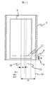
図1に第1の磁気遮蔽装置1が円筒形状であり、生体磁気、主に、心臓から発せする磁場を計測する場合の実施例の斜視図を示す。第1の磁気遮蔽装置1は単数または複数の径の異なる両端開放の円筒から構成される。実施例1では第1の円筒1_1と第2の円筒1_2から構成される。第1の磁気遮蔽装置1を構成する各円筒の配置は各円筒の中心軸が同軸で重なるように配置する。図1では第1の磁気遮蔽装置1を構成する円筒数は2つの場合の例を図示しているが、構成としては各円筒の厚み、長さ、円筒径によって磁気遮蔽率が決まるので、必要とする遮蔽率により円筒数は異なる。一般的な構成としては、第1の磁気遮蔽装置1を構成する円筒数は1から3の場合が適当である。第1の磁気遮蔽装置1を構成する円筒は高透磁率材料であるニッケルと鉄を主成分とするパーマロイ、ミューメタルより構成され、比透磁率は40000から200000程度となる。第1の磁気遮蔽装置1を構成する各円筒の厚みは0.5mmから3mmで、円筒径は0.5mから2m、円筒の長さは1mから2m程度となる。図2に実施例1の構成の断面図を示す。第2の磁気遮蔽装置3は第1の磁気遮蔽装置1の中央に配置され、第2の磁気遮蔽装置3の軸方向は第1の磁気遮蔽装置1の軸方向に対して略垂直に配置されている。略垂直方向に配置する理由は、垂直に配置した場合が第2の磁気遮蔽装置3による磁気遮蔽効果が最も高くなるからである。第2の磁気遮蔽装置3の筒両端は開放構成となっている。計測対象の磁場を計測するセンサー5は第2の磁気遮蔽装置3の筒内部に配置されセンサー5の磁場計測方向は第2の遮蔽装置3の軸と略平行に配置する。略平行に配置する理由は、センサー5の計測方向と第2の遮蔽装置3の軸とが平行の場合が最も磁気遮蔽効果が高く、また、計測される磁気信号の補正が容易に行うことができるからである。センサー5は複数配置されており、センサー配置面は第2の遮蔽措置3の計測対象側の開放短部面より10mmから50mm内部に配置される。この距離は、センサーがデュワー4内に配置されており、また、より内部に配置されることにより遮蔽効果が高くなるが、あまり名部に配置されるとセンサーと信号源との距離が離れるため、計測信号が弱くなってしまうことを考慮して決定している。
FIG. 1 shows a perspective view of an embodiment in which the first
本実施例では高感度な磁場センサーとしてSQUID(超伝導量子干渉素子)を用いる。ただし、本技術は他の磁気センサー、たとえばフラックスゲートなどにも応用可能な技術である。SQUIDは超伝導状態にして動作させるため、低温に冷却する必要がある。そのためSQUIDはデュワー4内に配置され、液体窒素、液体ヘリウムなどの冷媒により冷却されている。
In this embodiment, a SQUID (superconducting quantum interference device) is used as a highly sensitive magnetic field sensor. However, this technology can be applied to other magnetic sensors such as flux gates. Since SQUID operates in a superconducting state, it needs to be cooled to a low temperature. Therefore, the SQUID is disposed in the
図3に実際に作成した円筒型磁気遮蔽装置内に第2の遮蔽装置3を設置した場合と設置しなかった場合の環境磁気雑音の測定結果を示す。図中、縦軸は環境磁場値、横軸は周波数成分を示している。作成した円筒型磁気遮蔽装置は長楕円形の2重の磁気遮蔽装置で、長さが1.6m、開口部は長軸方向が1.4m、短軸方向が1.0m、各円筒壁間隔は0.1mで、各遮蔽円筒の磁性体の厚みは2mm、磁性体の比透磁率は約60000と見積もられている。この円筒型磁気遮蔽装置の磁気遮蔽率は約32dBである。この円筒型磁気遮蔽装置の中央に、直径0.4m、長さ0.6m、比透磁率約40000、磁性体厚み2mmの第2の遮蔽装置を設置した。図3では、◆シンボルで示されたのが第2の磁気遮蔽装置がない場合の環境磁気雑音スペクトル22、■シンボルで示されたの第2の磁気遮蔽装置を設置した場合の環境磁気雑音スペクトル23である。環境磁気雑音スペクトル22と環境磁気雑音スペクトル23を比較すると、10Hz以下の周波数帯域で、環境磁気雑音スペクトル23の方が2から5倍程度低い磁場値を示しており、第2の遮蔽装置3を設置したほうが環境磁気雑音の磁気遮蔽効果が高いことを示している。
FIG. 3 shows the measurement results of the environmental magnetic noise when the
図4に第2の磁気遮蔽装置3を有したことにより、同じ磁気遮蔽効果を保ちながら第1の磁気遮蔽装置1の長さを短くできることを示す。図4において、縦軸が第1の磁気遮蔽装置1の中心軸上の磁場の絶対値を示し、位置xは第2の磁気遮蔽装置3の中心軸を0としたときの第1の磁気遮蔽装置1の中心軸上の位置を示す。図4は数値シミュレーションにより得られた結果である。シミュレーション条件は、磁性体の比透磁率を40000、磁性体の厚みを5mm、第1の磁気遮蔽装置1の長さを2mと1,6m、第1の磁気遮蔽装置1の直径を1m、第2の磁気遮蔽装置3の長さを0.5m、第2の磁気遮蔽装置3の直径を0.25mとし、第1の磁気遮蔽装置1外部の磁場を300nT加えたときの結果である。外部磁場印加方向は第1の磁気遮蔽装置の中心軸と平行である。図中、◇シンボルで示すのが第1の磁場遮蔽装置1の長さが2m、第2の磁気遮蔽装置3がない場合の磁場値線24、*シンボルで示すのが第1の磁気遮蔽装置1の長さが1.6m、第2の磁気遮蔽装置3がない場合の磁場値線25、○シンボルで示すのが第1の磁気遮蔽装置1の長さが1.6m、第2の磁気遮蔽装置3がある場合の磁場値線26である。○シンボルは◇シンボルとほぼ同等で、さらに磁場の平坦度が優れている。図4の結果は、第2の磁気遮蔽装置3を設置することにより第1の磁気遮蔽装置の長さを2mから1.6mに短くしてもほぼ同等な磁気遮蔽効果が得られ、さらに第2の磁気遮蔽装置3内部での磁場平坦度が高い磁場遮蔽効果が得られることを示している。
FIG. 4 shows that by having the second
信号の計測は図5に示すように、センサー駆動回路34によりセンサー5を駆動し、センサー5からの信号を演算装置35に収録し、表示する。センサー駆動回路34は演算装置により制御される。
As shown in FIG. 5, the signal is measured by driving the
計測される磁場は第2の磁気遮蔽装置3を配置したことにより、第1の磁気遮蔽装置1の外側にある磁気雑音をより遮蔽することが可能となるが、計測対象の磁場、特に第2の遮蔽装置3に近い磁場は、第2の磁気遮蔽装置3が高透磁率材料で構成されているためにゆがめられる。そのゆがんだ磁場を模式的に表示したものを図6に示す。図6中(A)が第2の磁場遮蔽装置3がない従来構成を示しており、(B)が第2の磁場遮蔽装置3がある場合の構成となっている。紙面表から裏へ流れる信号源電流10_1と紙面裏から表へ流れる信号源電流10_2が流れることにより発生する磁場において、第2の磁場遮蔽装置がない場合は磁力線11、第2の磁場遮蔽装置がある場合は磁力線12として示しており、第2の磁場遮蔽装置がない場合のセンサー位置での磁場成分13と、第2の磁場遮蔽装置がある場合のセンサー位置での磁場成分14と、第2の磁場遮蔽装置がない場合のセンサーにより計測される垂直磁気成分15と第2の磁場遮蔽装置がある場合のセンサーにより計測される垂直磁気成分16を矢印で示している。第2の磁場遮蔽装置3がある場合、磁力線12は高透磁率材料から構成される第2の磁場遮蔽装置3へ引き寄せられるため、第2の磁場遮蔽装置3がない場合に比べ水平方向に曲がっている。そのため垂直方向の磁場成分16は小さくなる。磁場成分の大きさの違いを表示するため、第2の磁場遮蔽装置3がない場合の垂直磁気成分15の大きさを示す補助線27と第2の磁場遮蔽装置3がある場合の垂直磁気成分16の大きさを示す補助線28を示す。
The magnetic field to be measured can more effectively shield the magnetic noise outside the first
第2の磁場遮蔽装置3による垂直磁気成分の大きさの違いが信号源推定や、分布表示の誤差となるため、数値的に補正を行う。補正処理は演算装置35で行う。その数値補正方法は第2の磁場遮蔽装置3の半径drを正規化し、半径drを1とする。第2の磁場遮蔽装置3の中心軸18からセンサー5までの距離をdsとする。センサー5で計測した磁場の値をBz’とする。
Since the difference in the magnitude of the perpendicular magnetic component by the second magnetic
このときの補正磁場Bzを補正式(数1)とし計算する。図7にセンサー5の位置、第2の磁場遮蔽装置3の半径dr、第2の磁場遮蔽装置3の中心軸18からセンサー5までの距離をdsを示す。
Bz = Bz'×(α+e(−(1−ds)×β)) ・・・ (数1)
(数1)においてeは自然対数の底とする。α、βは第2の磁場遮蔽装置3の大きさ、磁性体の比透磁率、磁性体の厚さ、第2の磁気遮蔽装置3の計測対象側の開口端から、センサー計測面までの距離dhなどによって決まる値で、その決定には数値シミュレーションや実際に作製した第2の磁場遮蔽装置3の外部磁場に対する内部磁場分布を計測することにより決定する。シミュレーション及び実測方法は第2の磁気遮蔽装置の中心軸中央に、直径10から50mm程度の磁場発生コイル32を第2の磁気遮蔽装置3の計測面端部から10から100mm程度離した距離に配置して、第2の磁気遮蔽装置3内部の磁場分布を計算もしくは計測する。前記計算もしくは計測した結果と、第2の磁気遮蔽装置3がない場合の磁場分布の計算もしくは計測した値を用い(数1)におけるα、βを決定する。
The correction magnetic field Bz at this time is calculated using the correction formula (Equation 1). FIG. 7 shows the position of the
Bz = Bz '× (α + e (− (1−ds) × β) ) (Equation 1)
In (Equation 1), e is the base of the natural logarithm. α and β are the size of the second
図8に第2の磁場遮蔽装置3がある場合とない場合の磁気シミュレーション値とその第2の磁場遮蔽装置3がある場合の磁場値から(数1)を用いて補正した値を示す。図8では縦軸が磁場値、横軸が正規化した第2の磁場遮蔽装置の中心軸から第2の磁場遮蔽装置の筒壁までの距離を示し、0から1までの値をとる。縦軸の磁場値は極性があるが、図8では磁場値の大きさを比較しやすくするため絶対値を表示している。図8中、◇シンボルで示す線が第2の磁場遮蔽装置3がない場合の磁場シミュレーション値29、*シンボルで示す線が第2の磁場遮蔽装置3がある場合のシミュレーション磁場値30、○シンボルで示す線が(数1)により補正したシミュレーション磁場値31である。図9に図8の数値シミュレーションを行った、第2の磁場遮蔽装置3、センサー5、磁場発生コイル32の配置を示した断面図を示す。シミュレーションの条件は第2の磁場遮蔽装置3の比透磁率を40000、第2の磁場遮蔽装置3の円筒半径を200mm、第2の磁場遮蔽装置3の円筒の厚みを1mm、第2の磁場遮蔽装置3の円筒の長さを400mm、第2の磁気遮蔽装置3の計測面側端部を示す補助線8からセンサー5の計測面を示す補助線9までの距離を15mm、磁場発生コイル32の直径を10mm、磁場発生コイル32の巻き数を1回、磁場発生コイル32のコイル面33と第2の磁気遮蔽装置3の計測面側端部を示す補助線8との距離を55mm、磁場発生コイル32のコイル軸は第2の磁場遮蔽装置3の円筒軸と同じく配置し、磁場発生コイル32に流す電流値を1nAとした。上記条件での(数1)の係数α、βはそれぞれ、α=1.05、β=11。その結果、図8に示すように第2の磁場遮蔽装置3がある場合、第2の遮蔽装置の中心軸を示す補助線18から第2の磁気遮蔽装置の筒壁を示す補助線20までの距離drを1として正規化した時の第2の遮蔽装置の中心軸を示す補助線18からセンサー5の計測点を示す補助線20までの距離dsが0.3以下までは第2の磁場遮蔽装置3がない場合の磁場シミュレーション値29と第2の磁場遮蔽装置3がある場合のシミュレーション磁場値30との差が少ないが、dsが0.3を超えると差が生じ始め、第2の磁気遮蔽装置の筒壁を示す補助線20(つまり、dsが1)に近づくにつれて差が大きくなる。一方、(数1)により補正したシミュレーション磁場値3はdsが0.9以下の範囲で第2の磁場遮蔽装置3がない場合の磁場シミュレーション値29と一致している。従って、(数1)による補正式を使用する場合、センサー5はdsが0から0.9の範囲内に配置される。
FIG. 8 shows values corrected using (Equation 1) from the magnetic simulation values with and without the second magnetic
図10に第2の磁気遮蔽装置21が四角柱状であり、生体磁気、主に、心臓から発生する磁場を計測する場合の実施例の斜視図を示す。第1の磁気遮蔽装置1は単数または複数の径の異なる両端開放の円筒から構成される。実施例2では第1の円筒1_1と第2の円筒1_2から構成される。第1の磁気遮蔽装置1を構成する各円筒の配置は各円筒の中心軸が同軸で重なるように配置する。図10では第1の磁気遮蔽装置1を構成する円筒数は2つの場合の例を図示しているが、構成としては各円筒の厚み、長さ、円筒径によって磁気遮蔽率が決まるので、必要とする遮蔽率により円筒数は異なる。一般的な構成としては、第1の磁気遮蔽装置1を構成する円筒数は1から3の場合が適当である。第1の磁気遮蔽装置1を構成する円筒は高透磁率材料であるニッケルと鉄を主成分とするパーマロイ、ミューメタルより構成され、比透磁率は40000から200000程度となる。第1の磁気遮蔽装置1を構成する各円筒の厚みは0.5mmから3mmで、円筒径は0.5mから2m、円筒の長さは1mから2m程度となる。
FIG. 10 shows a perspective view of an embodiment in which the second
第2の磁気遮蔽装置21の筒形状は、4面からなり、筒軸に垂直となる断面は4角形となる形状場合の構成図を示す。図10では第2の磁場遮蔽装置の断面が4角形の場合を示しているが、第2の磁場遮蔽装置21の断面形状は4角形だけに限らず、多角形で形成される筒により実現可能である。磁気遮蔽効果は実施例1と同様であり、第2の磁気遮蔽装置21内部の磁場分布のゆがみ補正方法も実施例1と同様に行うことが可能である。第2の磁気遮蔽装置21の形状は、磁気センサー5を遮蔽するような形状であれば磁気遮蔽効果が得られるが、ゆがみ補正の演算のしやすさを考慮すると、磁気センサー5と平行な筒状であり、筒の断面が円または正多角形であることが望ましい。
The cylindrical shape of the 2nd
図11に補正領域を複数に分けて、それぞれの領域において補正式を距離の多項式に近似して補正を行う場合方法を示す。図では3つに分けている。演算装置35で行う数値補正において、第2の磁場遮蔽装置3の半径drを正規化し、半径drを1とする。drは3つの領域に分けられ、第2の磁場遮蔽装置3の中心軸から筒壁の順にdr1、dr2、dr3とする。各領域内の補正磁場は第2の磁場遮蔽装置3の中心軸から筒壁の順にBz1、Bz2、Bz3とする。第2の磁場遮蔽装置3の中心軸18からセンサー5までの距離をdsとする。センサー5で計測した磁場の値をBz’とする。
FIG. 11 shows a method in which correction is performed by dividing the correction area into a plurality of areas and approximating the correction formula to a polynomial of distance in each area. The figure is divided into three. In the numerical correction performed by the
このときの補正磁場Bzを領域dr1では補正式(数2)、領域dr2では補正式(数3)、領域dr3では補正式(数4)とし計算する。図7にセンサー5の位置、第2の磁場遮蔽装置3の半径dr、第2の磁場遮蔽装置3の中心軸18からセンサー5までの距離をdsを示す。
Bz1=Bz’×(α1×ds2+β1×ds+γ1)
…(数2)
Bz2=Bz’×(α2×ds2+β2×ds+γ2)
…(数3)
Bz3=Bz’×(α3×ds2+β3×ds+γ3)
…(数4)
(数2)(数3)(数4)において、それぞれα1、β1、γ1、α2、β2、γ2、α3、β3、γ3は第2の磁場遮蔽装置3の大きさ、磁性体の比透磁率、磁性体の厚さ、第2の磁気遮蔽装置3の計測対象側の開口端から、センサー計測面までの距離dhなどによって決まる値で、その決定には数値シミュレーションや実際に作製した第2の磁場遮蔽装置3の外部磁場に対する内部磁場分布を計測することにより決定する。シミュレーション及び実測方法は第2の磁気遮蔽装置の中心軸中央に、直径10から50mm程度の磁場発生コイル32を第2の磁気遮蔽装置3の計測面端部から10から100mm程度離した距離に配置して、第2の磁気遮蔽装置3内部の磁場分布を計算もしくは計測する。前記計算もしくは計測した結果と、第2の磁気遮蔽装置3がない場合の磁場分布の計算もしくは計測した値を用い(数2)(数3)(数4)におけるα1、β1、γ1、α2、β2、γ2、α3、β3、γ3を決定する。実施例3ではdrの領域を3つに分けているが、いくつに分けても同様に補正することが可能である。一般的には2から4が適当である。さらに補正式はセンサー5で計測した磁場の値をBz’にdsの2次関数を掛け合せて補正しているが、多次関数でも可能である。一般的には2から3次関数が適当である。補正領域を複数に領域分けすることの利点としては補正近似の精度が向上する。
The correction magnetic field Bz at this time is calculated as a correction equation (Equation 2) in the region dr 1 , a correction equation (Equation 3) in the region dr 2 , and a correction equation (Equation 4) in the region dr 3 . FIG. 7 shows the position of the
Bz 1 = Bz ′ × (α 1 × ds 2 + β 1 × ds + γ 1 )
... (Equation 2)
Bz 2 = Bz ′ × (α 2 × ds 2 + β 2 × ds + γ 2 )
(Equation 3)
Bz 3 = Bz ′ × (α 3 × ds 2 + β 3 × ds + γ 3 )
... (Equation 4)
In (Expression 2), (Expression 3), and (Expression 4), α 1 , β 1 , γ 1 , α 2 , β 2 , γ 2 , α 3 , β 3 , and γ 3 are the values of the second magnetic
演算装置35で行う数値補正において、(数1)及び(数2)(数3)(数4)における係数α、β及び、α1、β1、γ1、α2、β2、γ2、α3、β3、γ3を決定するための数値シミュレーションや実際に作製した第2の磁場遮蔽装置3の外部磁場に対する内部磁場分布を計測する方法として、第2の磁気遮蔽装置外部に、第2の磁気遮蔽装置3の直径及び長さより大きな直径を持つヘルムホルツコイルを用い、第2の磁気遮蔽装置3に軸に平行な一様磁場を加え、第2の磁気遮蔽装置内の磁場分布を計算もしくは計測を行う。
In the numerical correction performed by the
1・・・第1の磁気遮蔽装置、1_1・・・第1の円筒、1_2・・・第2の円筒、3・・・第2の磁気遮蔽装置、4・・・デュワー、5・・・センサー、6・・・ガントリー、7・・・ベッド、8・・・第2の磁気遮蔽装置3の計測面側端部を示す補助線、9・・・センサー5の計測面を示す補助線、10_1・・・紙面表から裏へ流れる信号源電流10_1、10_2・・・紙面裏から表へ流れる信号源電流、11・・・第2の磁気遮蔽装置がない場合の磁力線図、12・・・第2の磁気遮蔽装置がある場合の磁力線図、13・・・第2の磁気遮蔽装置がない場合のセンサー計測点での計測磁場ベクトル、14・・・第2の磁気遮蔽装置がある場合のセンサー計測点での磁場ベクトル、15・・・第2の磁気遮蔽装置がない場合のセンサー計測点での計測磁場ベクトル、16・・・第2の磁気遮蔽装置がある場合のセンサー計測点での計測磁場ベクトル、17・・・センサー計測点、18・・・第2の遮蔽装置の中心軸を示す補助線、19・・・センサー5の計測点を示す補助線、20・・・第2の磁気遮蔽装置の筒壁を示す補助線、21・・・実施例2における第2の磁気遮蔽装置、22・・・第2の磁気遮蔽装置がない場合の環境磁気雑音スペクトル、23・・・第2の磁気遮蔽装置を設置した場合の環境磁気雑音スペクトル、24・・・第1の磁場遮蔽装置1の長さが2m、第2の磁気遮蔽装置3がない場合の磁場値線、25・・・第1の磁気遮蔽装置1の長さが1.6m、第2の磁気遮蔽装置3がない場合の磁場値線、26・・・第1の磁気遮蔽装置1の長さが1.6m、第2の磁気遮蔽装置3がある場合の磁場値線、27・・・第2の磁場遮蔽装置3がない場合の垂直磁気成分15の大きさを示す補助線、28・・・第2の磁場遮蔽装置3がある場合の垂直磁気成分16の大きさを示す補助線、29・・・第2の磁場遮蔽装置3がない場合の磁場シミュレーション値、30・・・第2の磁場遮蔽装置3がある場合のシミュレーション磁場値、31・・・(数1)により補正したシミュレーション磁場値、32・・・磁場発生コイル、33・・・磁場発生コイル32のコイル面、34・・・センサー駆動回路、35・・・演算装置。
DESCRIPTION OF
Claims (10)
磁場検出方向が前記第1の磁気遮蔽装置の筒軸方向と略直交するよう配置され、前記第1の磁気遮蔽装置内に配置された単数もしくは複数の磁気センサーと、
両端もしくは、計測対象物に近いほうの1方向が開放の筒型に形成され、筒軸方向が前記磁場検出方向と略平行で、前記第1の磁気遮蔽装置内に配置され、筒内部に前記磁気センサーが配置される第2の磁気遮蔽装置と、
前記第2の磁気遮蔽装置により歪められた前記磁気センサーにより得られた信号を補正する演算手段とを有することを特徴とする磁場計測装置。 A first magnetic shielding device formed in a cylindrical shape having both ends open;
One or a plurality of magnetic sensors disposed in the first magnetic shielding device, the magnetic field detection direction being arranged so as to be substantially orthogonal to the cylinder axis direction of the first magnetic shielding device;
Both ends or one direction closer to the measurement object is formed into an open cylinder shape, the cylinder axis direction is substantially parallel to the magnetic field detection direction, and is arranged in the first magnetic shielding device, A second magnetic shielding device in which a magnetic sensor is disposed;
A magnetic field measuring apparatus comprising: an arithmetic means for correcting a signal obtained by the magnetic sensor distorted by the second magnetic shielding apparatus.
磁場検出方向が前記第1の磁気遮蔽装置の筒軸方向と略直交するよう配置され、前記第1の磁気遮蔽装置内に配置された単数もしくは複数の磁気センサーと、
両端もしくは、計測対象物に近いほうの1方向が開放の筒型に形成され、筒軸方向が前記磁場検出方向と略平行で、前記第1の磁気遮蔽装置内に配置され、筒内部に前記磁気センサーが配置される第2の磁気遮蔽装置と、
前記第2の磁気遮蔽装置により歪められた前記磁気センサーにより得られた信号を補正する演算手段とを有することを特徴とする磁場計測装置。 A first magnetic shielding device formed in a cylindrical shape having both ends open, wherein the length of the cylinder is shorter than twice the diameter of the cylinder;
One or a plurality of magnetic sensors disposed in the first magnetic shielding device, the magnetic field detection direction being arranged so as to be substantially orthogonal to the cylinder axis direction of the first magnetic shielding device;
Both ends or one direction closer to the measurement object is formed into an open cylinder shape, the cylinder axis direction is substantially parallel to the magnetic field detection direction, and is arranged in the first magnetic shielding device, A second magnetic shielding device in which a magnetic sensor is disposed ;
A magnetic field measuring apparatus comprising: an arithmetic means for correcting a signal obtained by the magnetic sensor distorted by the second magnetic shielding apparatus.
前記磁気センサーは、0から0.9の範囲内に配置されることを特徴とする請求項1または2記載の磁場計測装置。 When the position of the central axis of the second magnetic shielding device is normalized as 0 and the position of the cylindrical wall as 1,
The magnetic field measurement apparatus according to claim 1, wherein the magnetic sensor is disposed within a range of 0 to 0.9.
Priority Applications (5)
| Application Number | Priority Date | Filing Date | Title |
|---|---|---|---|
| JP2005170300A JP4671770B2 (en) | 2005-06-10 | 2005-06-10 | Magnetic field measuring device |
| US11/447,086 US7259570B1 (en) | 2005-06-10 | 2006-06-06 | Magnetic signal measurement apparatus |
| DE602006019024T DE602006019024D1 (en) | 2005-06-10 | 2006-06-06 | Device for measuring magnetic signals |
| EP06011643A EP1731917B1 (en) | 2005-06-10 | 2006-06-06 | Magnetic signal measurement apparatus |
| CNB2006100916865A CN100554991C (en) | 2005-06-10 | 2006-06-09 | Magnetic field measuring device |
Applications Claiming Priority (1)
| Application Number | Priority Date | Filing Date | Title |
|---|---|---|---|
| JP2005170300A JP4671770B2 (en) | 2005-06-10 | 2005-06-10 | Magnetic field measuring device |
Publications (3)
| Publication Number | Publication Date |
|---|---|
| JP2006340937A JP2006340937A (en) | 2006-12-21 |
| JP2006340937A5 JP2006340937A5 (en) | 2008-04-17 |
| JP4671770B2 true JP4671770B2 (en) | 2011-04-20 |
Family
ID=36949628
Family Applications (1)
| Application Number | Title | Priority Date | Filing Date |
|---|---|---|---|
| JP2005170300A Expired - Fee Related JP4671770B2 (en) | 2005-06-10 | 2005-06-10 | Magnetic field measuring device |
Country Status (5)
| Country | Link |
|---|---|
| US (1) | US7259570B1 (en) |
| EP (1) | EP1731917B1 (en) |
| JP (1) | JP4671770B2 (en) |
| CN (1) | CN100554991C (en) |
| DE (1) | DE602006019024D1 (en) |
Families Citing this family (18)
| Publication number | Priority date | Publication date | Assignee | Title |
|---|---|---|---|---|
| JP5165963B2 (en) * | 2007-08-14 | 2013-03-21 | 新科實業有限公司 | Magnetic sensor and manufacturing method thereof |
| JP4990194B2 (en) * | 2008-03-07 | 2012-08-01 | 株式会社神戸製鋼所 | Magnet position measurement method |
| JP2013077698A (en) * | 2011-09-30 | 2013-04-25 | Seiko Epson Corp | Magnetic shield |
| CN103033786B (en) * | 2011-10-08 | 2015-07-08 | 中国科学院空间科学与应用研究中心 | Quadrature calibration method and device of triaxial vector magnetometer |
| CN103472271B (en) * | 2012-06-08 | 2016-05-18 | 中国科学院空间科学与应用研究中心 | A kind of low-frequency band magnetic shielding cylinder |
| CN102743167B (en) * | 2012-07-06 | 2013-10-23 | 重庆金山科技(集团)有限公司 | Integrated shielded coil sensor for magnetic induction imaging system |
| CN104880680B (en) * | 2014-02-28 | 2017-12-05 | 中国科学院上海微系统与信息技术研究所 | Superconducting quantum interference device magnetic sensor-based system |
| JP6430201B2 (en) * | 2014-09-30 | 2018-11-28 | 株式会社東芝 | Sensor |
| CN104739411B (en) * | 2015-04-01 | 2017-04-05 | 南京医科大学 | A kind of use Magnetic Sensor carries out the method for detecting positioning to magnetic target |
| CN106291007B (en) * | 2015-06-02 | 2019-07-30 | 中国科学院物理研究所 | A kind of magnetic shielding device |
| CN105301549B (en) * | 2015-11-25 | 2018-10-12 | 广西电网有限责任公司电力科学研究院 | A kind of method and system for testing current transformer magnetic screen using three-dimensional magnetic field |
| CN108472074B (en) * | 2015-12-31 | 2021-06-29 | 圣犹达医疗用品国际控股有限公司 | Connector shield for sensor-enabled medical devices |
| GB2576579A (en) * | 2018-08-24 | 2020-02-26 | Magnetic Shields Ltd | Magnetic shield device |
| CN110703164B (en) * | 2019-10-18 | 2024-05-14 | 中国原子能科学研究院 | Magnetic shielding magnetic field measuring device of cyclotron |
| CN110702999B (en) * | 2019-11-21 | 2022-03-01 | 中国工程物理研究院应用电子学研究所 | Strong electromagnetic pulse shielding effectiveness test system and method |
| CN110907867B (en) * | 2019-12-13 | 2022-03-22 | 中国人民解放军国防科技大学 | Magnetic focusing device for giant magneto-impedance sensor and giant magneto-impedance sensor |
| CN111624537B (en) * | 2020-07-22 | 2022-11-04 | 北京航空航天大学杭州创新研究院 | Biological cell physical property testing device and testing method thereof |
| CN113040775A (en) * | 2021-03-22 | 2021-06-29 | 漫迪医疗仪器(上海)有限公司 | Biomagnetic detection device, biomagnetic detection method, storage medium and control terminal |
Citations (4)
| Publication number | Priority date | Publication date | Assignee | Title |
|---|---|---|---|---|
| JP2002136492A (en) * | 2000-10-30 | 2002-05-14 | Hitachi Ltd | Instrument for measuring magnetic field |
| JP2003339659A (en) * | 2002-05-23 | 2003-12-02 | Hitachi Ltd | Superconductive magnetic shield equipment |
| JP2004337478A (en) * | 2003-05-19 | 2004-12-02 | Hitachi Ltd | Magnetic field measuring device |
| JP2005131149A (en) * | 2003-10-31 | 2005-05-26 | Hitachi Ltd | Biomagnetism measuring device |
Family Cites Families (8)
| Publication number | Priority date | Publication date | Assignee | Title |
|---|---|---|---|---|
| JPH0697696A (en) | 1992-07-24 | 1994-04-08 | Dowa Mining Co Ltd | Superconductive magnetic shielding body |
| JPH09214166A (en) | 1996-01-29 | 1997-08-15 | Sumitomo Electric Ind Ltd | Magnetic shield |
| JPH11128193A (en) | 1997-10-29 | 1999-05-18 | Hitachi Ltd | Biomagnetism measurement device |
| KR100238446B1 (en) * | 1997-11-20 | 2000-01-15 | 정선종 | Ctl(circular transmission line) cell |
| JP3518502B2 (en) | 2000-10-19 | 2004-04-12 | 株式会社日立製作所 | Biomagnetic field measurement device |
| CN2457615Y (en) * | 2000-11-17 | 2001-10-31 | 中国人民解放军海军装备部驻重庆地区军事代表局 | Complex data detector of three shaft magnetic sensor |
| JP4110950B2 (en) | 2002-11-29 | 2008-07-02 | 株式会社日立製作所 | Magnetic shield device and biomagnetic field measurement device |
| JP4520904B2 (en) | 2005-06-03 | 2010-08-11 | 株式会社日立製作所 | Biomagnetic field measurement device |
-
2005
- 2005-06-10 JP JP2005170300A patent/JP4671770B2/en not_active Expired - Fee Related
-
2006
- 2006-06-06 US US11/447,086 patent/US7259570B1/en active Active
- 2006-06-06 EP EP06011643A patent/EP1731917B1/en not_active Ceased
- 2006-06-06 DE DE602006019024T patent/DE602006019024D1/en active Active
- 2006-06-09 CN CNB2006100916865A patent/CN100554991C/en not_active Expired - Fee Related
Patent Citations (4)
| Publication number | Priority date | Publication date | Assignee | Title |
|---|---|---|---|---|
| JP2002136492A (en) * | 2000-10-30 | 2002-05-14 | Hitachi Ltd | Instrument for measuring magnetic field |
| JP2003339659A (en) * | 2002-05-23 | 2003-12-02 | Hitachi Ltd | Superconductive magnetic shield equipment |
| JP2004337478A (en) * | 2003-05-19 | 2004-12-02 | Hitachi Ltd | Magnetic field measuring device |
| JP2005131149A (en) * | 2003-10-31 | 2005-05-26 | Hitachi Ltd | Biomagnetism measuring device |
Also Published As
| Publication number | Publication date |
|---|---|
| EP1731917B1 (en) | 2010-12-22 |
| US7259570B1 (en) | 2007-08-21 |
| CN1877354A (en) | 2006-12-13 |
| EP1731917A2 (en) | 2006-12-13 |
| EP1731917A3 (en) | 2010-03-10 |
| JP2006340937A (en) | 2006-12-21 |
| CN100554991C (en) | 2009-10-28 |
| DE602006019024D1 (en) | 2011-02-03 |
Similar Documents
| Publication | Publication Date | Title |
|---|---|---|
| JP4671770B2 (en) | Magnetic field measuring device | |
| US6534982B1 (en) | Magnetic resonance scanner with electromagnetic position and orientation tracking device | |
| Thiel et al. | Demagnetization of magnetically shielded rooms | |
| US10398341B2 (en) | Magnetic gradiometer element and magnetic gradiometer | |
| US8860414B2 (en) | Gradient coil arrangement | |
| EP0901638A4 (en) | Radiator calibration | |
| JP4740442B2 (en) | Unified shimming for magnetic resonance superconducting magnets | |
| JP3379488B2 (en) | Magnetic field measurement device | |
| JP2005003503A (en) | Magnetic-shielding method using induction coil | |
| Wang et al. | Design of compact self-shielded uniform magnetic field coils based on multipole moment optimization | |
| JPH02291840A (en) | Magnet for instrument forming magnetic resonance image | |
| CN116413646B (en) | Magnetic shielding equipment magnetic permeability measuring device | |
| CN101702183A (en) | Method used for united optimization of iron shielding type superconducting magnet | |
| Asfour et al. | Practical use of the gmi effect to make a current sensor | |
| JP2019181041A (en) | Active magnetic shield system and magnetocardiograph system using the same | |
| JP2015055520A (en) | Magnetic shield apparatus and magnetic shielding method | |
| JP6228931B2 (en) | Electromagnetic interference compensator during biomagnetism measurement | |
| JP7227609B2 (en) | Marker coil and magnetic measuring device | |
| JP6822222B2 (en) | Magnetic property measuring instrument, magnetic property measuring system, and magnetic property measuring method | |
| Saito | Features of a wall with open-type magnetic shielding method | |
| JP2005274544A (en) | Method for measuring magnetic leak characteristic of magnetic shield room | |
| Rühmer et al. | A shielded fluxgate sensor for spatially resolved measurements of magnetic dipole fields | |
| JP3424664B2 (en) | Magnetic field measurement device | |
| JP4273221B2 (en) | Active magnetic shield | |
| JP2001332888A (en) | Magnetic filed control system for magnetic-shield room |
Legal Events
| Date | Code | Title | Description |
|---|---|---|---|
| A521 | Request for written amendment filed |
Free format text: JAPANESE INTERMEDIATE CODE: A523 Effective date: 20080130 |
|
| A621 | Written request for application examination |
Free format text: JAPANESE INTERMEDIATE CODE: A621 Effective date: 20080130 |
|
| A521 | Request for written amendment filed |
Free format text: JAPANESE INTERMEDIATE CODE: A523 Effective date: 20080130 |
|
| A131 | Notification of reasons for refusal |
Free format text: JAPANESE INTERMEDIATE CODE: A131 Effective date: 20100914 |
|
| A521 | Request for written amendment filed |
Free format text: JAPANESE INTERMEDIATE CODE: A523 Effective date: 20101110 |
|
| TRDD | Decision of grant or rejection written | ||
| A01 | Written decision to grant a patent or to grant a registration (utility model) |
Free format text: JAPANESE INTERMEDIATE CODE: A01 Effective date: 20110104 |
|
| A01 | Written decision to grant a patent or to grant a registration (utility model) |
Free format text: JAPANESE INTERMEDIATE CODE: A01 |
|
| A61 | First payment of annual fees (during grant procedure) |
Free format text: JAPANESE INTERMEDIATE CODE: A61 Effective date: 20110118 |
|
| R150 | Certificate of patent or registration of utility model |
Ref document number: 4671770 Country of ref document: JP Free format text: JAPANESE INTERMEDIATE CODE: R150 Free format text: JAPANESE INTERMEDIATE CODE: R150 |
|
| FPAY | Renewal fee payment (event date is renewal date of database) |
Free format text: PAYMENT UNTIL: 20140128 Year of fee payment: 3 |
|
| LAPS | Cancellation because of no payment of annual fees |