JP4666968B2 - Image forming apparatus - Google Patents
Image forming apparatus Download PDFInfo
- Publication number
- JP4666968B2 JP4666968B2 JP2004211967A JP2004211967A JP4666968B2 JP 4666968 B2 JP4666968 B2 JP 4666968B2 JP 2004211967 A JP2004211967 A JP 2004211967A JP 2004211967 A JP2004211967 A JP 2004211967A JP 4666968 B2 JP4666968 B2 JP 4666968B2
- Authority
- JP
- Japan
- Prior art keywords
- density control
- image density
- image
- mode
- Prior art date
- Legal status (The legal status is an assumption and is not a legal conclusion. Google has not performed a legal analysis and makes no representation as to the accuracy of the status listed.)
- Expired - Fee Related
Links
Images


Description
本発明は画像形成装置に関し、特に、高精度な画像濃度補正を可能にする画像形成装置に関する。
The present invention relates to an image forming equipment, particularly relates to an image forming equipment which enables high-precision image density correction.
一般に、電子写真画像形成プロセスを用いた画像形成装置は、使用環境やプリント枚数などの諸条件によって画像濃度の変動が起こりやすい。特に複数色のトナー画像を重ね合わせてカラープリントを行なうカラー画像形成装置では、各色の画像濃度が変動すると、カラーバランス(いわゆる色味)の変動が生じてしまうので、濃度変動を抑制することが重要課題となる。 In general, an image forming apparatus using an electrophotographic image forming process is likely to vary in image density depending on various conditions such as a use environment and the number of prints. In particular, in a color image forming apparatus that performs color printing by superimposing a plurality of color toner images, if the image density of each color fluctuates, the color balance (so-called color) fluctuates. It becomes an important issue.
そこで、近年のカラー画像形成装置の多くは、感光体や中間転写体などの像担持体上、もしくは転写ベルトなどの転写材担持体上に検知用トナー画像(トナーパッチ)を試験的に作像し、トナーパッチのトナー量を光学式センサで検知し、検知結果から露光量、現像バイアス等にフィードバックをかけて画像濃度制御を行って、安定した画像を得るようにしている。このようなカラー画像形成装置は、例えば、特開平11−65237号公報に記載されている。
しかしながら、上述した従来の画像形成装置には、以下のような不具合があった。 However, the conventional image forming apparatus described above has the following problems.
一般的に電子写真方式のプリンタは、複数のプリントモードを有している場合が多い。例えば、プリントスピードに関しては、普通紙などに印字するための通常速プリントモードと、厚紙などへの印字を行なう低速プリントモードとを有している場合がある。また出力する画像の種類に応じた最適な出力を得るために、プリンタの解像度やハーフトーンスクリーン線数を変えた複数のプリントモードを有する場合もある。
このように、複数のプリントモードを有するプリンタにおいては、プリントモードが変われば、画像濃度特性も変わってしまうのが普通である。従って、全てのプリントモードで良好なカラーバランスを得るためには、それぞれのプリントモード毎に画像濃度制御を行なう必要がある。
In general, an electrophotographic printer often has a plurality of print modes. For example, the print speed may have a normal speed print mode for printing on plain paper and a low speed print mode for printing on cardboard. In addition, in order to obtain an optimum output corresponding to the type of image to be output, there may be a plurality of print modes in which the resolution of the printer and the number of halftone screen lines are changed.
As described above, in a printer having a plurality of print modes, when the print mode changes, the image density characteristic usually changes. Therefore, in order to obtain a good color balance in all print modes, it is necessary to perform image density control for each print mode.
ところが、多くのモードに対して画像濃度制御を実施した場合、画像濃度制御に要する時間が長くなってしまい、この分プリント待ち時間が増加することになり、ユーザーの不快感を招いてしまうことになる。さらに、画像濃度制御時に多くのトナー画像パッチを印字することになるので、その分トナーの消費量も増加してしまう。つまり、プリントコストの増加を招いてしまうことになる。 However, when the image density control is performed for many modes, the time required for the image density control becomes longer, and the print waiting time increases accordingly, which causes the user to feel uncomfortable. Become. Further, since many toner image patches are printed at the time of image density control, the amount of toner consumption increases accordingly. That is, the printing cost is increased.
一方で、複数のプリントモードを有しているものの、画像濃度制御は代表的な1つのプリントモードでのみ実行して、画像濃度制御を実行しないプリントモードに対しては、画像濃度制御を実施したプリントモードにおける制御結果から予測補正を実施するような製品もある。そのような製品では、画像濃度制御は最も一般的な普通紙のプリントモードに対して実行される場合が多い。しかしながら、例えばユーザーが低速プリントモード(厚紙プリントなど)しか使わないようなケースでは、画像濃度制御がユーザーの使用プリントモードで実行されていないので、プリント画像のカラーバランスは不安定なものになってしまう(普通紙プリントモードでの画像濃度制御結果から予測補正を実施したとしても、低速プリントモードでの濃度制御をしていないので、高精度の濃度補正は期待できない)。 On the other hand, although it has multiple print modes, image density control is executed only in one representative print mode, and image density control is executed for print modes that do not execute image density control. Some products perform predictive correction based on the control result in the print mode. In such products, image density control is often performed for the most common plain paper print mode. However, for example, in the case where the user uses only the low-speed print mode (such as cardboard printing), the color balance of the printed image becomes unstable because the image density control is not executed in the user's use print mode. (Even if predictive correction is performed from the image density control result in the plain paper print mode, high-precision density correction cannot be expected because the density control is not performed in the low-speed print mode).
本発明は、このような状況のもとでなされたものであり、プリンタのダウンタイムおよびプリントコストの増加を極力抑えつつ、良好なカラーバランスの出力画像を得ることのできる画像形成装置を提供することを目的とする。 The present invention has been made under such circumstances, and provides an image forming apparatus capable of obtaining an output image having a good color balance while suppressing an increase in printer downtime and printing cost as much as possible. For the purpose.
以上の課題を解決するために、本発明による画像形成装置は、複数のプリントモードにおける画像形成動作を実行すると共に、前記複数のプリントモードの各々に対応した複数の画像濃度制御モードで画像濃度制御を実行する画像形成装置であって、検知用トナー像の光反射特性を検出する検出手段と、実行する前記画像濃度制御モードを選択する画像濃度制御モード選択手段と、前記選択された画像濃度制御モードの画像濃度制御で前記検知用トナー像を形成し、前記検出手段による前記形成された検知用トナー像の検出結果に基づき、画像データの階調値を変化させるテーブルを設定する画像濃度制御手段と、設定されたテーブルに基づいて画像形成を実行する画像形成手段と、を備え、前記画像濃度制御モード選択手段は、前記複数の画像濃度制御モードから1つ以上の実行する画像濃度制御モードを選択可能であり、更に前記画像濃度制御モード選択手段は、前記画像濃度制御手段により前記検知用トナー像の形成及び検知と、前記テーブルの設定とを行う画像濃度制御モードとして、前記複数のプリントモードの各使用頻度に基づき、予め定められた使用頻度以上のプリントモードが1つの場合には該1つのプリントモードに対応する画像濃度制御モードを選択し、前記使用頻度以上のプリントモードが複数の場合にはそれぞれのプリントモードに対応する複数の画像濃度制御モードを選択することを特徴とする。
In order to solve the above problems, an image forming apparatus according to the present invention executes image forming operations in a plurality of print modes and controls image density in a plurality of image density control modes corresponding to each of the plurality of print modes. An image forming apparatus for detecting the light reflection characteristic of the detection toner image, an image density control mode selecting unit for selecting the image density control mode to be executed, and the selected image density control. Image density control means for forming a detection toner image by image density control in a mode and setting a table for changing a gradation value of image data based on a detection result of the formed detection toner image by the detection means And image forming means for executing image formation based on the set table, and the image density control mode selecting means includes the plurality of image density control mode selecting means. An image density control mode for one or more executable from the image density control mode can be selected, further wherein the image density control mode selection means, the formation and detection of the detection toner image by the image density control means, said table As the image density control mode for setting the image density , when there is one print mode that is equal to or higher than a predetermined use frequency based on each use frequency of the plurality of print modes, the image density control corresponding to the one print mode is performed. A mode is selected, and a plurality of image density control modes corresponding to each print mode are selected when there are a plurality of print modes that are more than the use frequency .
なお、その他の本発明の特徴は、添付図面及び以下の発明を実施するための最良の形態の記載によっていっそう明らかになるものである。 Other features of the present invention will become more apparent from the accompanying drawings and the following description of the best mode for carrying out the invention.
以上説明したように、本発明によれば、複数のプリントモードを有する画像形成装置において、どのプリントモードに対応する画像濃度制御を実施するかを好適に選択することにより、プリンタのダウンタイムおよびプリントコストの増加を極力抑えつつ、良好なカラーバランスの出力画像を得ることが可能になる。 As described above, according to the present invention, an image forming apparatus having a plurality of print modes, by suitably selecting to Rukoto whether to implement the image density control corresponding to the throat print mode, down the printer An output image with a good color balance can be obtained while suppressing an increase in time and printing cost as much as possible.
以下、図面を参照して第1乃至第4の実施形態について説明するが、まず各実施形態に共通な事項について説明し、その後各実施形態の説明に移行することとする。なお、各実施形態にかかる画像形成装置としては、たとえば電子写真複写機、電子写真プリンタ(たとえばLEDプリンタ、レーザビームプリンタ等)、電子写真ファクシミリ、および電子写真ワードプロセッサー等が含まれる。 Hereinafter, the first to fourth embodiments will be described with reference to the drawings. First, matters common to the respective embodiments will be described, and then the description of each embodiment will be made. The image forming apparatus according to each embodiment includes, for example, an electrophotographic copying machine, an electrophotographic printer (for example, an LED printer, a laser beam printer), an electrophotographic facsimile, an electrophotographic word processor, and the like.
<各実施形態に共通なカラー画像形成装置の全体構成図>
各実施形態では、通常速のプリントモードと低速のプリントモードを有する画像形成装置において、ユーザーがどの速度のプリントモードに対して画像濃度制御を実施するかを選択可能にすることにより、プリンタのダウンタイムおよびプリントコストの増加を極力抑えつつ、良好なカラーバランスの出力画像を得る方法について説明する。
<Overall Configuration of Color Image Forming Apparatus Common to Each Embodiment>
In each embodiment, in an image forming apparatus having a normal speed print mode and a low speed print mode, the user can select which speed print mode the image density control is to be performed on. A method of obtaining an output image with a good color balance while suppressing an increase in time and printing cost as much as possible will be described.
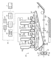
図1は、各実施形態に共通なカラー画像形成装置の全体構成を示す断面図である。この装置は、図示のように、電子写真方式のカラー画像形成装置の一例である中間転写体27を採用したタンデム方式のカラー画像形成装置である。本カラー画像形成装置は、図1に示す画像形成部20と画像処理部10から構成される。
FIG. 1 is a cross-sectional view showing an overall configuration of a color image forming apparatus common to the embodiments. As shown in the figure, this apparatus is a tandem color image forming apparatus that employs an
以下、図1を用いて、電子写真方式のカラー画像形成装置における、画像形成部の動作を説明する。 Hereinafter, the operation of the image forming unit in the electrophotographic color image forming apparatus will be described with reference to FIG.
まず、画像処理部10において、ホストコンピュータ1から入力された画像データはインタフェース11を介してCPUに入力され、必要に応じて所定の画像処理が行われる。本発明に関する画像処理については、濃度制御処理が関連する。例えば、この濃度制御処理の際には、ROM13に格納された制御プログラムが読み出され、そのプログラムに従って画像処理された画像データは必要に応じて一時的にRAM14に格納される。その画像処理が終了した画像データはPWM復号処理部15に入力されてPWM復号される。処理後その画像データは各レーザドライバ24Y、24M、24C,24Kに入力されて画像形成処理に移行することとなる。なお、濃度制御処理の詳細についてはさらに後述する。
First, in the
画像形成部20は、画像処理部が変換した露光時間に基づいて点灯させる露光光により静電潜像を形成し、この静電潜像を現像して単色トナー像を形成し、この単色トナー像を重ね合わせて多色トナー像を形成し、この多色トナー像を転写材35へ転写し、その転写材35上の多色トナー像を定着させるもので、給紙部21、現像色分並置したステーション毎の感光体(22Y、22M、22C、22K)、一次帯電手段としての注入帯電手段(23Y、23M、23C、23K)、トナーカートリッジ(25Y、25M、25C、25K)、現像手段(26Y、26M、26C、26K)、中間転写体27、転写ローラ28、クリーニング手段29、定着部30、濃度センサ41及びカラーセンサ(図示せず)によって構成されている。
The
感光ドラム(感光体)22Y、22M、22C、22Kは、アルミシリンダの外周に有機光導伝層を塗布して構成し、図示しない駆動モータの駆動力が伝達されて回転するもので、駆動モータは感光ドラム22Y、22M、22C、22Kを画像形成動作に応じて反時計周り方向に回転させる。
The photosensitive drums (photoconductors) 22Y, 22M, 22C, and 22K are configured by applying an organic optical conductive layer to the outer periphery of an aluminum cylinder, and are rotated by the driving force of a driving motor (not shown) being transmitted. The
一次帯電手段として、ステーション毎にイエロー(Y)、マゼンダ(M)、シアン(C)、ブラック(K)の感光体を帯電させるための4個の注入帯電器23Y、23M、23C、23Kを備える構成で、各注入帯電器にはスリーブ23YS、23MS、23CS、23KSが備えられている。
As the primary charging means, four
感光ドラム22Y、22M、22C、22Kへの露光光はスキャナ部24Y、24M、24C、24Kから送られ、感光ドラム22Y、22M、22C、22Kの表面を選択的に露光することにより、静電潜像が形成されるように構成されている。
Exposure light to the
現像手段として、前記静電潜像を可視化するために、ステーション毎にイエロー(Y)、マゼンダ(M)、シアン(C)、ブラック(K)の現像を行う4個の現像器26Y、26M、26C、26Kを備える構成で、各現像器には、スリーブ26YS、26MS、26CS、26KSが設けられている。各々の現像器は脱着可能に取り付けられている。 As developing means, in order to visualize the electrostatic latent image, four developing devices 26Y, 26M for developing yellow (Y), magenta (M), cyan (C), and black (K) for each station, Each developing device is provided with a sleeve 26YS, 26MS, 26CS, and 26KS. Each developing device is detachably attached.
中間転写体27は、感光ドラム22Y、22M、22C、22Kに接触しており、カラー画像形成時に時計周り方向に回転し、感光ドラム22Y、22M、22C、22Kの回転に伴って回転し、単色トナー像が転写される。その後、中間転写体27に後述する転写ローラ28が接触して転写材35を狭持搬送し、転写材35に中間転写体27上の多色トナー像が転写する。
The
転写ローラ28は、転写材35上に多色トナー像を転写している間、28aの位置で転写材35に当接し、印字処理後は28bの位置に離間する。
The transfer roller 28 contacts the
定着部30は、転写材35を搬送させながら、転写された多色トナー像を溶融定着させるものであり、図1に示すように転写材35を加熱する定着ローラ31と転写材35を定着ローラ31に圧接させるための加圧ローラ32を備えている。定着ローラ31と加圧ローラ32は中空状に形成され、内部にそれぞれヒータ33、34が内蔵されている。すなわち、多色トナー像を保持した転写材35は定着ローラ31と加圧ローラ32により搬送されるとともに、熱および圧力を加えられ、トナーが表面に定着される。
The
トナー像定着後の転写材35は、その後図示しない排出ローラによって図示しない排紙トレイに排出して画像形成動作を終了する。
After the toner image is fixed, the
クリーニング手段29は、中間転写体27上に残ったトナーをクリーニングするものであり、中間転写体27上に形成された4色の多色トナー像を転写材35に転写した後の廃トナーは、クリーナ容器に蓄えられる。
The
濃度センサ41は、トナー量を検出するための光学センサであり、画像濃度制御に用いられる。濃度センサ41は、図1のカラー画像形成装置において中間転写体27へ向けて配置されており、中間転写体27の表面上に形成されたトナーパッチの濃度を測定する。この濃度センサ41の構成の一例を図2に示す。LEDなどの赤外発光素子51と、フォトダイオード等の受光素子52、受光データを処理する図示しないICなどとこれらを収容する図示しないホルダーで構成される。
The
赤外発光素子51は、中間転写体27の垂直方向に対して45度の角度で設置されており、赤外光を中間転写体27上のトナーパッチ64に照射させる。受光素子52は、発光素子51に対して対称位置に設置されているおり、トナーパッチ64からの正反射光を検出する。
The infrared
なお、前記発光素子51と受光素子52の結合のために図示しないレンズなどの光学素子が用いられることもある。
An optical element such as a lens (not shown) may be used for coupling the
また、本実施形態において、中間転写体27は周長880mmのポリイミド製の単層樹脂ベルトである。また、ベルトの抵抗調整のために適量のカーボン微粒子が樹脂内に分散されており、表面色は黒色である。更に、中間転写体27の表面は、平滑性が高く光沢性を有しており、光沢度は約100%(堀場製作所製光沢計IG−320で測定)である。
In the present embodiment, the
濃度センサ41は、中間転写体27の表面が露出している状態(トナー量が0)のときには、受光素子52が反射光を検出する。理由は、前述のように中間転写体27の表面が光沢性を有するからである。一方、中間転写体27にトナー像が形成された場合、トナー像の濃度(トナー量)が増加するに従って、正反射出力は次第に減少していく。これは、トナーが中間転写体27の表面を覆い隠すことにより、ベルト表面からの正反射光が減少するからである。
In the
図3は、濃度センサの検出値とトナー量との関係を示す図である。図3中縦軸は、濃度センサの出力電圧を表し、横軸は画像濃度(トナー量に相当する)を表している。尚、本実施例に使用した濃度センサーは、最大出力電圧が5Vである。図3中、曲線Aは、濃度センサの汚れがなく、且つ中間転写体に汚れや光沢低下がない場合の出力特性を示している。一方、曲線Bは、濃度センサが汚れている場合の出力特性を示しており、曲線Aに比べて出力電圧が減少している。濃度センサが汚れると出力電圧が低下してしまうので、本実施例の画像形成装置では、トナーが無い状態の中間転写体の出力値(下地出力値)を用いて、濃度センサの出力補正を行っている。具体的には、トナーパッチの出力値を中間転写体の下地出力値(図3中濃度0の出力値)で正規化している。(トナーパッチ出力/下地出力)。
FIG. 3 is a diagram illustrating the relationship between the detection value of the density sensor and the toner amount. In FIG. 3, the vertical axis represents the output voltage of the density sensor, and the horizontal axis represents the image density (corresponding to the toner amount). The density sensor used in this example has a maximum output voltage of 5V. In FIG. 3, a curve A shows the output characteristics when the density sensor is not soiled and the intermediate transfer member is free of soiling and gloss reduction. On the other hand, the curve B shows the output characteristics when the density sensor is dirty, and the output voltage is reduced compared to the curve A. Since the output voltage decreases when the density sensor becomes dirty, the image forming apparatus of this embodiment performs output correction of the density sensor using the output value (background output value) of the intermediate transfer member in the absence of toner. ing. Specifically, the output value of the toner patch is normalized by the background output value of the intermediate transfer member (output value of
正規化後のセンサ出力特性は、図4に示すようになり、濃度センサの汚れにかかわらず出力値が一致する。尚、中間転写ベルトの光沢が汚れ、傷等により低下した場合も同様の補正が可能である。 The sensor output characteristics after normalization are as shown in FIG. 4, and the output values match regardless of the density sensor contamination. The same correction can be made when the gloss of the intermediate transfer belt is lowered due to dirt, scratches, or the like.
以上説明したトナーパッチ出力を下地出力で正規化補正する方法は、公知の手法であり、上市されている多くのカラー画像形成装置で用いられている。また、中間転写体の下地測定はトナーパッチの形成箇所と同一の箇所で行なうことが好ましい。特に、中間転写ベルトの汚れや傷が不均一に生じる場合(こうなってしまうことが普通である)、トナーパッチの位置と下地測定位置を同一にすることが不可欠である。本実施例の画像形成装置においても、すべてのトナーパッチに対して、パッチが形成される一周前の中間転写体上の下地(パッチと同一位置)を測定している。 The above-described method for normalizing and correcting the toner patch output with the background output is a known method, and is used in many commercially available color image forming apparatuses. In addition, it is preferable to measure the background of the intermediate transfer member at the same location as the toner patch formation location. In particular, when the intermediate transfer belt is unevenly stained or scratched (usually this is the case), it is indispensable to make the toner patch position and the ground measurement position the same. Also in the image forming apparatus of the present embodiment, for all the toner patches, the base (on the same position as the patch) on the intermediate transfer body before the patch is formed is measured.
<各実施形態共通の画像濃度制御動作について>
次に、各実施形態における画像濃度制御について、図5のフローチャートを用いて説明する。
<Common Image Density Control Operation for Each Embodiment>
Next, image density control in each embodiment will be described with reference to the flowchart of FIG.
尚、本発明の画像形成装置における画像濃度制御は、画像の濃度階調特性を調整する画像階調制御である。 Note that the image density control in the image forming apparatus of the present invention is image gradation control for adjusting the density gradation characteristics of the image.
まず、画像濃度制御は、画像濃度の変動が予想される場合に実施される。具体的には、以下の条件のいずれかに当てはまるときに実行される。
1.本体電源のON時
2.現像器もしくは感光体の交換時
3.装置が長時間使用されていない状態(本実施例では1時間)でプリント命令を受けた時
4.所定の枚数(本実施例では、100枚)がプリントされた場合
である。尚、画像濃度制御をどのプリントモードで実行するかは、後述する画像濃度制御モードの選択方法に従う。
First, the image density control is performed when a change in image density is expected. Specifically, it is executed when any of the following conditions is met.
1. 1. When main unit power is ON 2. When changing the developing unit or photoconductor 3. When a print command is received when the device has not been used for a long time (1 hour in this embodiment). This is a case where a predetermined number (100 in this embodiment) is printed. Note that in which print mode image density control is executed depends on a selection method of an image density control mode described later.
ステップS101において、中間転写体の下地測定が実行される。測定位置及びポイント数は、画像濃度制御に使用されるトナーパッチと同じにする。 In step S101, the background measurement of the intermediate transfer member is executed. The measurement position and the number of points are the same as those of the toner patch used for image density control.
ここで、図6は、中間転写体上に形成されるパッチパターンを示す図であり、濃度センサ41の配置されている部分に8mm角のパッチが2mm間隔で、Y,M,C,K毎に画像印字率(濃度階調度)を8段階に変化させて(各色8パッチずつ)、合計32個形成されている。各パッチと印字率(階調度)との対応は、Y1,M1,C1,K1=12.5%、Y2,M2,C2,K2=25%、Y3,M3,C3,K3=37.5%、Y4,M4,C4,K4=50%、Y5,M5,C5,K5=62.5%、Y6,M6,C6,K6=75%、Y7,M7,C7,K7=87.5%、Y8,M8,C8,K8=100%、に設定されている。
Here, FIG. 6 is a diagram showing a patch pattern formed on the intermediate transfer member, and 8 mm square patches are provided at intervals of 2 mm on the portion where the
中間転写体の下地測定は、上述の32個のパッチが形成される場所に対して、パッチが形成される以前に(パッチ形成の1周前に)行われる。 The background measurement of the intermediate transfer member is performed before the patch is formed (one round before the patch formation) at the location where the 32 patches are formed.
図5に戻り、ステップS102において、中間転写体上にトナーパッチが形成される。パッチの詳細は、図6で説明したとおりである。 Returning to FIG. 5, in step S102, a toner patch is formed on the intermediate transfer member. Details of the patch are as described in FIG.
そして、ステップS103において、濃度センサでトナーパッチからの反射光量が検出され、ステップS104においてトナーパッチの濃度が算出される。つまり、まず、トナーパッチの出力値を中間転写体の下地出力値で正規化され(トナー出力/下地出力)、パッチ出力の正規化は全てのパッチについて、パッチに対応する下地出力を用いて行われる。次に、正規化後の値を濃度変換テーブルにより濃度値に変換する。濃度変換テーブルは、装置本体のROM13に予め記憶されている。
In step S103, the density sensor detects the amount of light reflected from the toner patch, and in step S104, the density of the toner patch is calculated. That is, first, the output value of the toner patch is normalized by the background output value of the intermediate transfer member (toner output / background output), and the patch output is normalized using the background output corresponding to the patch for all patches. Is called. Next, the normalized value is converted into a density value using a density conversion table. The density conversion table is stored in advance in the
続いて、ステップS105において、画像階調制御(階調補正)が実施される。この画像階調制御については、図7を用いて説明をする。尚、ここでは、シアン色の階調補正についてのみ説明するが、マゼンタ、イエロー、ブラックに関しても同様の方法で補正が行われる。 Subsequently, in step S105, image gradation control (gradation correction) is performed. This image gradation control will be described with reference to FIG. Here, only cyan tone correction will be described, but magenta, yellow, and black are also corrected in the same manner.
図7において、横軸は画像データを表し、縦軸は、濃度センサ41の濃度検出値(STEP7で算出)を表している。また、図中○印は、C1,Cに,C3,C4,C5,C6,C7,C8各パッチに対する濃度センサ41の検出濃度値を表している。次に、直線Tは、画像濃度制御の目標濃度階調特性をあらわしている。本発明においては、画像データと濃度の関係が比例関係になるように目標濃度階調特性Tが定められている。
In FIG. 7, the horizontal axis represents the image data, and the vertical axis represents the density detection value (calculated in STEP 7) of the
曲線γは、濃度制御(階調補正制御)を実施していない状態での濃度階調特性をあらわしている。尚、パッチを形成していない階調の濃度については、原点及びC1,Cに,C3,C4,C5,C6,C7,C8を通るようにスプライン補間行い算出される。 A curve γ represents a density gradation characteristic in a state where density control (tone correction control) is not performed. It should be noted that the density of gradations not forming a patch is calculated by spline interpolation through C3, C4, C5, C6, C7, and C8 through the origin and C1 and C.
曲線Dは、本制御で算出される階調補正テーブルを表しており、補正前の階調特性γの目標階調特性Tに対する対称ポイントを求めることにより算出される。尚、階調補正テーブルDの計算は、CPU12で実行され、更に算出された階調補正テーブルDは、RAM14に記憶される。
A curve D represents a gradation correction table calculated by this control, and is calculated by obtaining a symmetric point with respect to the target gradation characteristic T of the gradation characteristic γ before correction. The calculation of the gradation correction table D is executed by the
プリント画像の形成時は、画像データを階調補正テーブルDで補正することにより、目標階調特性を得ることができる。 When the print image is formed, the target gradation characteristics can be obtained by correcting the image data with the gradation correction table D.
以上が、本実施例における画像濃度制御(画像階調補正)についての説明である。 The above is the description of the image density control (image gradation correction) in the present embodiment.
<第1の実施形態>
次に、第1の実施形態の特徴である画像濃度制御モードの選択方法について説明する。
<First Embodiment>
Next, a method for selecting an image density control mode, which is a feature of the first embodiment, will be described.
本実施形態の画像形成装置は、普通紙にプリントするための通常速プリントモード(プロセススピード100mm/sec)と厚紙プリントのための低速プリントモード(プロセススピード50mm/sec)の2つのプリントモードを有しているものとする。
The image forming apparatus of the present embodiment has two print modes: a normal speed print mode (
また、2つのプリントモードに対応する2つ画像濃度制御モード(普通紙用画像濃度制御と厚紙用画像濃度制御)を有している。それぞれの画像濃度制御モードは、対応するプリントモードに合わせて、制御時の画像形成速度が設定されている。すなわち、普通紙用画像濃度制御では、通常速のプロセススピードで制御を行い、厚紙用画像濃度制御では、低速のプロセススピードで制御を行なう。一般に、プロセス速度が異なると、感光体の暗減衰、明減衰や、現像特性が異なり、同一の濃度階調特性にはならないため、この方法が良い。 In addition, there are two image density control modes (plain paper image density control and thick paper image density control) corresponding to the two print modes. In each image density control mode, the image forming speed at the time of control is set in accordance with the corresponding print mode. In other words, the normal paper image density control is performed at a normal process speed, and the thick paper image density control is performed at a low process speed. In general, when the process speed is different, the dark decay, bright decay, and development characteristics of the photosensitive member are different, and the density gradation characteristics are not the same.
次に、前述の画像濃度制御モードを実行する判断方法について図8のフローチャートを用いて説明する。 Next, a determination method for executing the above-described image density control mode will be described with reference to the flowchart of FIG.
ステップS201において、普通紙用画像濃度制御を実行するか否か判断を行なう。尚、普通紙用画像濃度制御モードのON/OFF選択は、ユーザーが装置本体のオペレーションパネルの選択メニューから入力する。例えば、ユーザーが普通紙プリントを多く行なうので、普通紙プリントの画像濃度を安定させたい場合は、普通紙用画像濃度制御モードの実行ONを選択されており、処理はステップS202に移行する。逆に、ユーザーが普通紙プリントをあまり行なわないので、普通紙プリントの画像濃度の安定性を確保するための普通紙用画像濃度制御モードを実行せずに、むしろ装置のダウンタイムをなるべく少なくしたい場合は、普通紙用画像濃度制御モードの実行OFFが選択され、処理はステップS203に移行する。 In step S201, it is determined whether to execute image density control for plain paper. The ON / OFF selection of the image density control mode for plain paper is input from the selection menu on the operation panel of the apparatus main body by the user. For example, since the user performs many plain paper prints, when it is desired to stabilize the image density of the plain paper print, execution ON of the plain paper image density control mode is selected, and the process proceeds to step S202. On the contrary, since the user does not print plain paper much, instead of executing the normal paper image density control mode for ensuring the stability of the image density of the plain paper print, it is desirable to reduce the downtime of the apparatus as much as possible. In this case, execution OFF of the plain paper image density control mode is selected, and the process proceeds to step S203.
ステップS202及びステップS203においては、厚紙用画像濃度制御を実行するか否かが判断される。実行する場合には処理はステップS204(ステップS203の場合はステップS206)に移行する。また、実行しない場合には処理はステップS205(ステップS203の場合はステップS207)に移行する。尚、厚紙用画像濃度制御モードのON/OFF選択も、ユーザーが装置本体のオペレーションパネルの選択メニューから入力する。例えば、ユーザーが厚紙プリントを多く行なうので、厚紙プリントの画像濃度を安定させたい場合は、厚紙用画像濃度制御モードの実行ONを選択する。逆に、ユーザーが厚紙プリントをあまり行なわないので、厚紙プリントの画像濃度の安定性を確保するための厚紙用画像濃度制御モードを実行せずに、むしろ装置のダウンタイムをなるべく少なくしたい場合は、厚紙用画像濃度制御モードの実行OFFを選択する。 In step S202 and step S203, it is determined whether or not to execute cardboard image density control. If so, the process proceeds to step S204 (step S206 in the case of step S203). If not, the process proceeds to step S205 (in the case of step S203, step S207). The user also inputs ON / OFF selection of the card density image density control mode from the selection menu on the operation panel of the apparatus main body. For example, since the user performs many thick paper prints, if the image density of thick paper prints is to be stabilized, execution ON of the thick paper image density control mode is selected. On the contrary, since the user does not perform cardboard printing so much, if the user wants to reduce the downtime of the apparatus as much as possible without executing the cardboard image density control mode for ensuring the stability of the image density of the cardboard print, Select execution OFF of the image density control mode for cardboard.
ステップS204においては、普通紙用画像濃度制御モードおよび厚紙用の画像濃度制御モードの実行選択がされているので、両方のモードで画像濃度制御を実施する。この場合、2つのモードで画像濃度制御を実施するので、普通紙プリント、厚紙プリントともに良好なカラーバランスを得ることができる。 In step S204, since execution selection of the image density control mode for plain paper and the image density control mode for cardboard is selected, image density control is performed in both modes. In this case, since image density control is performed in two modes, good color balance can be obtained for both plain paper printing and thick paper printing.
また、ステップS205においては、普通紙用画像濃度制御モードのみ実行選択がされているので、普通紙用画像濃度制御モードの画像濃度制御を実施する。この場合、厚紙用画像濃度制御を実行しないのでその分の制御時間短縮が図れる。また、ユーザーが主に使用する普通紙プリントモードにおいて良好なカラーバランスを得ることができる。 In step S205, only the plain paper image density control mode is selected to be executed, so the image density control in the plain paper image density control mode is performed. In this case, since the card density control is not executed, the control time can be reduced accordingly. In addition, a good color balance can be obtained in the plain paper print mode mainly used by the user.
尚、厚紙用プリントモードに対しては、普通紙用画像濃度制御の制御結果から予測補正を実施する。そうすることにより、厚紙プリント時においても、ある程度のレベルでの色安定性を得ることができる。 For the thick paper print mode, prediction correction is performed from the control result of the plain paper image density control. By doing so, color stability at a certain level can be obtained even when printing on thick paper.
そして、ステップS206においては、厚紙用画像濃度制御モードのみ実行選択がされているので、厚紙用画像濃度制御モードの画像濃度制御を実施する。この場合、普通紙用画像濃度制御を実行しないのでその分の制御時間短縮が図れる。また、ユーザーが主に使用する厚紙プリントモードにおいて良好なカラーバランスを得ることができる。 In step S206, only the cardboard image density control mode is selected to be executed, so image density control in the cardboard image density control mode is performed. In this case, since the image density control for plain paper is not executed, the control time can be reduced accordingly. In addition, a good color balance can be obtained in the cardboard print mode mainly used by the user.
尚、普通紙用プリントモードに対しては、厚紙用画像濃度制御の制御結果から予測補正を実施する。そうすることにより、普通紙プリント時においても、ある程度のレベルでの色安定性を得ることができる。 For the plain paper print mode, prediction correction is performed based on the control result of the thick paper image density control. By doing so, color stability at a certain level can be obtained even when printing on plain paper.
また、ステップS207においては、普通紙用画像濃度制御モード、厚紙用の画像濃度制御モードともに実行しない様に選択されているので、画像濃度制御は実施しない。この場合、普通紙プリント、厚紙プリントともに良好なカラーバランスは期待できない。一方、プリンタのダウンタイムは最小に抑えられる。例えば、プリント画像の色安定性よりもプリントスピードを重要視するユーザー等が、このケースを選択する。 In step S207, since it is selected not to execute both the image density control mode for plain paper and the image density control mode for thick paper, image density control is not performed. In this case, good color balance cannot be expected for both plain paper printing and cardboard printing. On the other hand, printer downtime is minimized. For example, a user who places importance on print speed rather than color stability of a print image selects this case.
以上が、第1の実施形態における画像濃度制御モードの選択方法についての説明である。 This completes the description of the method for selecting the image density control mode in the first embodiment.
このように第1の実施形態によれば、通常速のプリントモードと低速のプリントモードを有する画像形成装置において、ユーザーがどの速度のプリントモードに対して画像濃度制御を実施するかを選択可能にしているので、プリンタのダウンタイムおよびプリントコストの増加を極力抑えつつ、良好なカラーバランスの出力画像を得ることができるようになる。 As described above, according to the first embodiment, in the image forming apparatus having the normal speed print mode and the low speed print mode, the user can select which speed print mode the image density control is performed on. Therefore, an output image with a good color balance can be obtained while suppressing an increase in printer downtime and printing cost as much as possible.
<第2の実施形態>
第2の実施形態では、高解像度のプリントモードと低解像度のプリントモードを有する画像形成装置において、ユーザーがどの解像度のプリントモードに対して画像濃度制御を実施するかを選択可能にすることにより、プリンタのダウンタイムおよびプリントコストの増加を極力抑えつつ、良好なカラーバランスの出力画像を得る方法について説明する。 第2の実施形態の画像形成装置は、写真画像などをプリントするための低解像度プリントモード(解像度600dpi)とCAD画像などをプリントするための高解像度プリントモード(解像度1200dpi)の2つのプリントモードを有しているものとする。
<Second Embodiment>
In the second embodiment, in an image forming apparatus having a high-resolution print mode and a low-resolution print mode, the user can select which resolution print mode the image density control is performed by, A method for obtaining an output image with a good color balance while minimizing an increase in printer downtime and printing cost will be described. The image forming apparatus of the second embodiment has two print modes: a low resolution print mode (resolution 600 dpi) for printing photographic images and the like, and a high resolution print mode (resolution 1200 dpi) for printing CAD images and the like. It shall have.
また、2つのプリントモードに対応する2つ画像濃度制御モード(高解像度用画像濃度制御と低解像度用画像濃度制御)を有している。それぞれの画像濃度制御モードは、対応するプリントモードに合わせて、制御時の画像形成解像度が設定されている。一般に、プリント解像度を高くすると、より滑らかな形状の潜像を形成することが可能になる。逆に、低解像度では、輪郭がぎざぎざの潜像しか形成できない。すなわち、同じハーフトーン線数であったとしても、ミクロな領域で潜像状態が異なる為、濃度階調特性にはならない(高解像度の方がよりスムーズな階調特性になる)。従って、プリント解像度を一致させた濃度制御が必要になる。 Also, there are two image density control modes (high resolution image density control and low resolution image density control) corresponding to the two print modes. In each image density control mode, the image forming resolution at the time of control is set in accordance with the corresponding print mode. In general, when the print resolution is increased, a latent image having a smoother shape can be formed. Conversely, at low resolution, only a latent image with a jagged outline can be formed. In other words, even if the number of halftone lines is the same, the latent image state is different in a micro area, so that density gradation characteristics are not obtained (higher resolution results in smoother gradation characteristics). Therefore, it is necessary to perform density control with matching print resolution.
図9は、画像濃度制御モードを実行する判断方法についてのフローチャートである。 FIG. 9 is a flowchart of a determination method for executing the image density control mode.
ステップS301において、高解像度用画像濃度制御を実行するか否かが判断される。尚、高解像度用画像濃度制御モードのON/OFF選択は、第1の実施形態と同様にユーザーが装置本体のオペレーションパネルの選択メニューから入力する。例えば、ユーザーがCAD画像等のプリントを多く行なうので、高解像度プリントの画像濃度を安定させたい場合は、高解像度用画像濃度制御モードの実行ONを選択し、この場合には、処理はステップS302に移行する。逆に、ユーザーが高解像度プリントをあまり行なわない場合は、高解像度用画像濃度制御モードの実行OFFを選択し、この場合には、処理はステップS303に移行する。 In step S301, it is determined whether to execute high-resolution image density control. Note that ON / OFF selection of the high-resolution image density control mode is input by the user from the selection menu on the operation panel of the apparatus main body, as in the first embodiment. For example, since the user often prints CAD images and the like, if it is desired to stabilize the image density of the high resolution print, execution ON of the image density control mode for high resolution is selected. In this case, the process is step S302. Migrate to Conversely, if the user does not perform much high-resolution printing, execution OFF of the high-resolution image density control mode is selected, and in this case, the process proceeds to step S303.
ステップS302及びS303においては、低解像度用画像濃度制御を実行するか否かが判断される。実行する場合には処理はステップS304(ステップS303の場合はステップS306)に移行する。また、実行しない場合には処理はステップS305(ステップS303の場合はステップS307)に移行する。尚、低解像度用画像濃度制御モードのON/OFF選択も、ユーザーが装置本体のオペレーションパネルの選択メニューから入力する。例えば、ユーザーが写真画像のプリントを多く行なうので、低解像度プリントの画像濃度を安定させたい場合は、低解像度用画像濃度制御モードの実行ONを選択する。逆に、ユーザーが低解像度プリントをあまり行なわない場合は、厚紙用画像濃度制御モードの実行OFFを選択する。 In steps S302 and S303, it is determined whether or not to execute low-resolution image density control. If so, the process proceeds to step S304 (in the case of step S303, step S306). If not, the process proceeds to step S305 (in the case of step S303, step S307). Note that the user also inputs ON / OFF selection of the low-resolution image density control mode from the selection menu on the operation panel of the apparatus main body. For example, since the user prints many photographic images, if the image density of the low resolution print is to be stabilized, the execution ON of the low resolution image density control mode is selected. Conversely, if the user does not perform much low resolution printing, execution OFF of the card density control mode for thick paper is selected.
ステップS304においては、高解像度用画像濃度制御モードおよび低解像度用の画像濃度制御モードの実行選択がされているので、両方のモードで画像濃度制御を実施する。この場合、2つのモードで画像濃度制御を実施するので、高解像度プリント、低解像度プリントともに良好なカラーバランスを得ることができる。 In step S304, since execution selection of the image density control mode for high resolution and the image density control mode for low resolution is selected, image density control is performed in both modes. In this case, since image density control is performed in two modes, good color balance can be obtained for both high-resolution printing and low-resolution printing.
ステップS305においては、高解像度用画像濃度制御モードのみ実行選択がされているので、高解像度用画像濃度制御モードの画像濃度制御を実施する。この場合、低解像度用画像濃度制御を実行しないのでその分の制御時間短縮が図れる。また、ユーザーが主に使用する高解像度プリントモードにおいて良好なカラーバランスを得ることができる。 In step S305, only the high-resolution image density control mode is selected to be executed, so image density control in the high-resolution image density control mode is performed. In this case, since the low-resolution image density control is not executed, the control time can be reduced accordingly. In addition, a good color balance can be obtained in a high resolution print mode mainly used by the user.
また、ステップS306においては、低解像度用画像濃度制御モードのみ実行選択がされているので、低解像度用画像濃度制御モードの画像濃度制御を実施する。この場合、高解像度用画像濃度制御を実行しないのでその分の制御時間短縮が図れる。また、ユーザーが主に使用する低解像度プリントモードにおいて良好なカラーバランスを得ることができる。 In step S306, only the low resolution image density control mode is selected to be executed, and therefore image density control in the low resolution image density control mode is performed. In this case, since the high-resolution image density control is not executed, the control time can be reduced accordingly. In addition, a good color balance can be obtained in the low resolution print mode mainly used by the user.
そして、ステップS307においては、高解像度用画像濃度制御モード、低解像度画像濃度制御モードともに実行しない様に選択されているので、画像濃度制御は実施しない。この場合、高解像度プリント、低解像度プリントともに良好なカラーバランスは期待できない。一方、プリンタのダウンタイムは最小に抑えられる。例えば、プリント画像の色安定性よりもプリントスピードを重要視するユーザー等が、このケースを選択する。 In step S307, since it is selected not to execute both the high resolution image density control mode and the low resolution image density control mode, image density control is not performed. In this case, good color balance cannot be expected for both high resolution printing and low resolution printing. On the other hand, printer downtime is minimized. For example, a user who places importance on print speed rather than color stability of a print image selects this case.
以上、第2の実施形態によれば、高解像度のプリントモードと低解像度のプリントモードを有する画像形成装置において、ユーザーがどの解像度のプリントモードに対して画像濃度制御を実施するかを選択可能にするので、プリンタのダウンタイムおよびプリントコストの増加を極力抑えつつ、良好なカラーバランスの出力画像を得ることができるようになる。 As described above, according to the second embodiment, in the image forming apparatus having the high resolution print mode and the low resolution print mode, the user can select which resolution print mode the image density control is to be performed on. Therefore, it is possible to obtain an output image with a good color balance while suppressing an increase in printer downtime and printing cost as much as possible.
<第3の実施形態>
第3の実施形態では、ハーフトーンスクリーンの線数(以下HT線数)を変えた2種類のプリントモードを有する画像形成装置において、ユーザーがどのHT線数のプリントモードに対して画像濃度制御を実施するかを選択可能にすることにより、プリンタのダウンタイムおよびプリントコストの増加を極力抑えつつ、良好なカラーバランスの出力画像を得る方法について説明する。
<Third Embodiment>
In the third embodiment, in an image forming apparatus having two types of print modes in which the number of lines of the halftone screen (hereinafter referred to as HT lines) is changed, the user performs image density control for which HT line number of print modes. A method of obtaining an output image with a good color balance while minimizing an increase in printer downtime and printing cost by making it possible to select whether to execute will be described.
第3の実施形態の画像形成装置は、写真画像などをプリントするための低線数プリントモード(HT線数150lpi)とグラフィック画像やテキスト画像などをプリントするための高線数プリントモード(HT線数200lpi)の2つのプリントモードを有しているものとする。 The image forming apparatus according to the third embodiment includes a low line number print mode (HT line number 150 lpi) for printing photographic images and the like, and a high line number print mode (HT line) for printing graphic images, text images, and the like. It is assumed that there are two print modes of several 200 lpi).
また、2つのプリントモードに対応する2つ画像濃度制御モード(高線数用画像濃度制御と低線数用画像濃度制御)を有している。それぞれの画像濃度制御モードは、対応するプリントモードに合わせて、制御時の画像形成HT線数が設定されている。一般に、ハーフトーン線数が異なると濃度階調特性にはならない(線数を下げるとスムーズな階調性になる)。従って、プリント解像度を一致させた濃度制御が必要になる。 Also, two image density control modes (high line number image density control and low line number image density control) corresponding to two print modes are provided. In each image density control mode, the number of image forming HT lines at the time of control is set in accordance with the corresponding print mode. In general, if the number of halftone lines is different, density gradation characteristics are not obtained (smooth gradation characteristics are obtained when the number of lines is decreased). Therefore, it is necessary to perform density control with matching print resolution.
図10は、第3の実施形態に係る画像濃度制御モードを実行する判断方法についてのフローチャートを示している。 FIG. 10 shows a flowchart of a determination method for executing the image density control mode according to the third embodiment.
ステップS401において、高線数用画像濃度制御を実行するか否かが判断される。尚、高線数用画像濃度制御モードのON/OFF選択は、第1の実施形態と同様にユーザーが装置本体のオペレーションパネルの選択メニューから入力する。例えば、ユーザーがグラフィック画像やテキスト画像等のプリントを多く行なうので、高線数プリントの画像濃度を安定させたい場合は、高線数用画像濃度制御モードの実行ONを選択し、この場合には、処理はステップS402に移行する。逆に、ユーザーが高線数プリントをあまり行なわない場合は、高線数用画像濃度制御モードの実行OFFを選択し、この場合には処理はステップS403に移行する。 In step S401, it is determined whether or not to execute image density control for a high number of lines. The ON / OFF selection of the image density control mode for high line number is input by the user from the selection menu on the operation panel of the apparatus main body, as in the first embodiment. For example, since the user often prints graphic images, text images, etc., if the image density of high line number printing is to be stabilized, the execution of the high line number image density control mode is selected. The process proceeds to step S402. On the other hand, if the user does not print much high line number, execution OFF of the high line number image density control mode is selected. In this case, the process proceeds to step S403.
ステップS402及びステップS403においては、低線数用画像濃度制御を実行するか否かが判断される。実行する場合には処理はステップS404(ステップS403の場合はステップS406)に移行する。また、実行しない場合には処理はステップS405(ステップS403の場合はステップS407)に移行する。尚、低線数用画像濃度制御モードのON/OFF選択も、ユーザーが装置本体のオペレーションパネルの選択メニューから入力する。例えば、ユーザーが写真画像のプリントを多く行なうので、低線数プリントの画像濃度を安定させたい場合は、低線数用画像濃度制御モードの実行ONを選択する。逆に、ユーザーが低線数プリントをあまり行なわない場合は、低線数用画像濃度制御モードの実行OFFを選択する。 In step S402 and step S403, it is determined whether or not to execute low line number image density control. If so, the process proceeds to step S404 (in the case of step S403, step S406). If not, the process proceeds to step S405 (in the case of step S403, step S407). Note that the user also inputs ON / OFF selection of the image density control mode for low number of lines from the selection menu on the operation panel of the apparatus main body. For example, since the user prints many photographic images, if the image density of the low line number print is to be stabilized, the execution ON of the low line number image density control mode is selected. Conversely, when the user does not perform much low line number printing, execution OFF of the low line number image density control mode is selected.
ステップS404においては、高線数用画像濃度制御モードおよび低線数用の画像濃度制御モードの実行選択がされているので、両方のモードで画像濃度制御を実施する。この場合、2つのモードで画像濃度制御を実施するので、高線数プリント、低線数プリントともに良好なカラーバランスを得ることができる。 In step S404, since execution selection of the image density control mode for high line number and the image density control mode for low line number is selected, image density control is performed in both modes. In this case, since image density control is performed in two modes, good color balance can be obtained for both high line number printing and low line number printing.
ステップS405においては、高線数用画像濃度制御モードのみ実行選択がされているので、高線数用画像濃度制御モードの画像濃度制御を実施する。この場合、低線数用画像濃度制御を実行しないのでその分の制御時間短縮が図れる。また、ユーザーが主に使用する高線数プリントモードにおいて良好なカラーバランスを得ることができる。 In step S405, only the high line number image density control mode is selected to be executed, so image density control in the high line number image density control mode is performed. In this case, since the image density control for the low number of lines is not executed, the control time can be reduced accordingly. In addition, a good color balance can be obtained in the high-line number print mode mainly used by the user.
また、ステップS406においては、低線数用画像濃度制御モードのみ実行選択がされているので、低線数用画像濃度制御モードの画像濃度制御を実施する。この場合、高線数用画像濃度制御を実行しないのでその分の制御時間短縮が図れる。また、ユーザーが主に使用する低線数プリントモードにおいて良好なカラーバランスを得ることができる。 In step S406, only the low line number image density control mode is selected to be executed, so image density control in the low line number image density control mode is performed. In this case, since the high line number image density control is not executed, the control time can be reduced accordingly. In addition, a good color balance can be obtained in the low-line-number print mode mainly used by the user.
さらに、ステップS407においては、高線数用画像濃度制御モード、低線数画像濃度制御モードともに実行しない様に選択されているので、画像濃度制御は実施しない。この場合、高線数プリント、低線数プリントともに良好なカラーバランスは期待できない。一方、プリンタのダウンタイムは最小に抑えられる。例えば、プリント画像の色安定性よりもプリントスピードを重要視するユーザー等が、このケースを選択する。 Further, in step S407, since it is selected not to execute both the high line number image density control mode and the low line number image density control mode, the image density control is not performed. In this case, good color balance cannot be expected for both high line number printing and low line number printing. On the other hand, printer downtime is minimized. For example, a user who places importance on print speed rather than color stability of a print image selects this case.
以上、第3の実施形態によれば、HT線数を変えた2種類のプリントモードを有する画像形成装置において、ユーザーがどのHT線数のプリントモードに対して画像濃度制御を実施するかを選択可能にしているので、プリンタのダウンタイムおよびプリントコストの増加を極力抑えつつ、良好なカラーバランスの出力画像を得ることができるようになる。 As described above, according to the third embodiment, in an image forming apparatus having two types of print modes with different HT line numbers, the user selects which HT line number print modes the image density control is to be performed on. Therefore, an output image with a good color balance can be obtained while suppressing an increase in printer downtime and printing cost as much as possible.
<第4の実施形態>
第4の実施形態では、複数のプリントモードを有する画像形成装置において、どのプリントモードに対して画像濃度制御を実施するかをプリント履歴に応じて自動選択することにより、プリンタのダウンタイムおよびプリントコストの増加を極力抑えつつ、良好なカラーバランスの出力画像を得る方法について説明する。
<Fourth Embodiment>
In the fourth embodiment, in an image forming apparatus having a plurality of print modes, which print mode is to be subjected to image density control is automatically selected according to the print history, so that the printer downtime and print cost can be selected. A method for obtaining an output image with a good color balance while suppressing an increase in the image as much as possible will be described.
尚、第4の実施形態の画像形成装置は、第1の実施形態と同様に普通紙をプリントするための通常速プリントモード(プロセススピード100mm/sec)と厚紙プリントのための低速プリントモード(プロセススピード50mm/sec)の2つのプリントモードを有しているものとする。また、2つのプリントモードに対応する2つ画像濃度制御モード(普通紙用画像濃度制御と厚紙用画像濃度制御)を有している。それぞれの画像濃度制御モードは、対応するプリントモードに合わせて、制御時の画像形成速度が設定されている。
Note that the image forming apparatus according to the fourth embodiment has a normal speed print mode (
図11は、第4の実施形態に係る画像濃度制御モードの自動選択方法についてのフローチャートである。 FIG. 11 is a flowchart of an image density control mode automatic selection method according to the fourth embodiment.
ステップS501においては、普通紙プリントの使用頻度に応じて、普通紙用画像濃度制御を実行するか否かが判断される。普通紙プリントの使用頻度は、装置本体内のCPU12が記憶する画像濃度制御以前のプリントモード履歴から算出される。本実施形態では、例えば過去500枚プリント中の普通紙プリントの比率を算出している。
In step S501, it is determined whether or not to execute image density control for plain paper according to the use frequency of plain paper print. The use frequency of plain paper print is calculated from the print mode history before image density control stored in the
普通紙プリントのプリント頻度が5%以上のときは、ユーザーが普通紙プリントを比較的多く行なうので、普通紙プリントの画像濃度を安定させるために普通紙用画像濃度制御モードを実行するように判断する。普通紙プリントの比率が5%以上の場合には、処理はステップS502に移行し、5%以上でない場合には処理はステップS505に移行する。 When the print frequency of plain paper print is 5% or more, the user performs plain paper print relatively, so that it is determined to execute the plain paper image density control mode in order to stabilize the image density of plain paper print. To do. If the ratio of plain paper printing is 5% or more, the process proceeds to step S502, and if not 5% or more, the process proceeds to step S505.
ステップS502において、厚紙用画像濃度制御を実行するか否かが判断される。つまり、厚紙プリントの比率が5%以上か否かが判断され、5%以上であれば処理はステップS503に移行し、5%以上でなければ処理はステップS504に移行する。厚紙プリントのプリント頻度(過去500枚プリント中)が5%以上のときは、ユーザーが厚紙プリントを比較的多く行なうので、厚紙プリントの画像濃度を安定させるために厚紙用画像濃度制御モードを実行するように判断する。 In step S502, it is determined whether or not to execute the card density control for cardboard. That is, it is determined whether the ratio of thick paper printing is 5% or more. If it is 5% or more, the process proceeds to step S503, and if it is not 5% or more, the process proceeds to step S504. When the printing frequency of cardboard printing (during the past 500 prints) is 5% or more, the user performs relatively cardboard printing, so the cardboard image density control mode is executed in order to stabilize the cardboard image density. Judge as follows.
ステップS503においては、普通紙用画像濃度制御モードおよび厚紙用の画像濃度制御モードの実行選択がされているので、両方のモードで画像濃度制御を実施する。この場合、2つのモードで画像濃度制御を実施するので、普通紙プリント、厚紙プリントともに良好なカラーバランスを得ることができる。 In step S503, since the execution selection of the image density control mode for plain paper and the image density control mode for cardboard is selected, image density control is performed in both modes. In this case, since image density control is performed in two modes, good color balance can be obtained for both plain paper printing and thick paper printing.
また、ステップS504においては、普通紙用画像濃度制御モードのみ実行選択がされているので、普通紙用画像濃度制御モードの画像濃度制御を実施する。この場合、厚紙用画像濃度制御を実行しないのでその分の制御時間短縮が図れる。また、ユーザーが主に使用する普通紙プリントモードにおいて良好なカラーバランスを得ることができる。 In step S504, only the plain paper image density control mode is selected to be executed, so image density control in the plain paper image density control mode is performed. In this case, since the card density control is not executed, the control time can be reduced accordingly. In addition, a good color balance can be obtained in the plain paper print mode mainly used by the user.
さらに、ステップS506においては、プリント履歴のほとんどが厚紙プリントなので、厚紙用画像濃度制御モードの画像濃度制御を実施する。この場合、普通紙用画像濃度制御を実行しないのでその分の制御時間短縮が図れる。また、ユーザーが主に使用する厚紙プリントモードにおいて良好なカラーバランスを得ることができる。 Further, in step S506, since most of the print history is thick paper print, image density control in the thick paper image density control mode is performed. In this case, since the image density control for plain paper is not executed, the control time can be reduced accordingly. In addition, a good color balance can be obtained in the cardboard print mode mainly used by the user.
尚、第4の実施形態では、プリント頻度の算出を過去500枚のプリント履歴から算出し、また画像濃度制御モードの実行判断プリント頻度を5%としたが、これらのプリント履歴枚数や判断プリント頻度レベルは、本発明を適用する画像形成装置の特性に合わせて最適な値を設定すればよい。 In the fourth embodiment, the print frequency is calculated from the print history of the past 500 sheets, and the execution determination print frequency in the image density control mode is set to 5%. The level may be set to an optimum value according to the characteristics of the image forming apparatus to which the present invention is applied.
また、第4の実施形態に係る発明は、プリントスピードの異なるモードを有する画像形成装置のみならず、プリント解像度やHT線数の異なるモードを有する画像形成装置にも適用可能である。 The invention according to the fourth embodiment can be applied not only to an image forming apparatus having modes with different print speeds but also to an image forming apparatus having modes with different print resolutions and HT line numbers.
以上、第4の実施形態によれば、複数のプリントモードを有する画像形成装置において、どのプリントモードに対して画像濃度制御を実施するかをプリント履歴に応じて自動選択するようにしているので、プリンタのダウンタイムおよびプリントコストの増加を極力抑えつつ、良好なカラーバランスの出力画像を得ることができるようになる。 As described above, according to the fourth embodiment, in the image forming apparatus having a plurality of print modes, for which print mode image density control is performed is automatically selected according to the print history. An output image with a good color balance can be obtained while suppressing an increase in printer downtime and printing cost as much as possible.
<その他の実施形態>
尚、第1乃至第4の実施形態では、カラー画像形成装置の形態として、中間転写体を用いた画像形成装置を例に説明したが、本発明は他の形態のカラー画像形成装置にも適用可能である。例えば、転写材担持体(転写ベルトなど)上の転写材に感光体上のトナー像を直接的に転写する形態のカラー画像形成装置であり、転写材担持体上にトナーパッチを形成して濃度制御を行うようなカラー画像形成装置にも本発明は適用できる。
<Other embodiments>
In the first to fourth embodiments, the image forming apparatus using the intermediate transfer member is described as an example of the color image forming apparatus. However, the present invention is also applicable to color image forming apparatuses of other forms. Is possible. For example, a color image forming apparatus in which a toner image on a photosensitive member is directly transferred onto a transfer material on a transfer material carrier (such as a transfer belt), and a toner patch is formed on the transfer material carrier to form a density. The present invention can also be applied to a color image forming apparatus that performs control.
た、第1乃至第4の実施形態では、プリントモードとして、プリントスピード、解像度、ハーフトーン線数が独立に異なる場合を例にあげて説明したが、無論これらの条件が組み合わさって、変更されるような複数のプリントモードを有する画像形成装置にも本発明は適用できる(例えば、低解像度で普通速のプリントモードと高解像度で低速のプリントモードとを有するような場合)。 In the first to fourth embodiments, the print mode, the case where the print speed, the resolution, and the number of halftone lines are different from each other have been described as an example, but of course these conditions are combined and changed. The present invention can also be applied to an image forming apparatus having a plurality of print modes (for example, having a low-resolution, normal-speed print mode and a high-resolution, low-speed print mode).
更に、第1乃至第4の実施形態では、画像濃度制御の方法として、画像の濃度階調特性を調整する画像階調制御を例に挙げて説明したが、画像濃度制御の方法は他の方法でも良い。例えば、現像バイアス値や帯電バイアス値を変化させて複数のトナーパッチを形成した後、それらのパッチのトナー量を算出し、その値に応じて最適な現像バイアス値や帯電バイアス値を算出することによって、濃度を制御するような方法でも構わない。 Furthermore, in the first to fourth embodiments, the image density control for adjusting the density gradation characteristics of the image has been described as an example of the image density control method. However, the image density control method is another method. But it ’s okay. For example, after forming a plurality of toner patches by changing the developing bias value and the charging bias value, calculating the toner amount of those patches, and calculating the optimum developing bias value and charging bias value according to the values. The method of controlling the density may be used.
また、第1乃至第4の実施形態では、濃度センサがトナーパッチを検出した際の、光反射特性に対応するトナー量として濃度を用いる場合を例に説明したが、濃度センサが検出する光反射特性に対応するトナー量とは、これに限らず、当然、トナー重量そのものでもよく、更には色度などを用いてもよい。つまり、トナーパッチからの光反射特性を元に換算されるトナー量に対応する物理量を光学センサが検出する形態であれば、本発明の適用範囲にあることは言うまでもない。 In the first to fourth embodiments, the case where the density is used as the toner amount corresponding to the light reflection characteristic when the density sensor detects the toner patch is described as an example. However, the light reflection detected by the density sensor is used. The toner amount corresponding to the characteristic is not limited to this, and naturally, the toner weight itself may be used, and further, chromaticity may be used. That is, it goes without saying that the present invention is within the scope of the present invention as long as the optical sensor detects a physical quantity corresponding to the toner quantity converted based on the light reflection characteristic from the toner patch.
なお、本発明では、実施形態の機能を実現するソフトウェアのプログラムコードを記録した記憶媒体をシステム或は装置に提供し、そのシステム或は装置のコンピュータ(又はCPUやMPU)が記憶媒体に格納されたプログラムコードを読み出し実行することによっても達成される。この場合、記憶媒体から読み出されたプログラムコード自体が前述した実施形態の機能を実現することになり、そのプログラムコードを記憶した記憶媒体は本発明を構成することになる。このようなプログラムコードを供給するための記憶媒体としては、例えば、フロッピィ(登録商標)ディスク、ハードディスク、光ディスク、光磁気ディスク、CD−ROM,CD−R、磁気テープ、不揮発性のメモリカード、ROMなどを用いることができる。 In the present invention, a storage medium in which a program code of software that realizes the functions of the embodiments is recorded is provided to a system or apparatus, and a computer (or CPU or MPU) of the system or apparatus is stored in the storage medium. It is also achieved by reading and executing the program code. In this case, the program code itself read from the storage medium realizes the functions of the above-described embodiments, and the storage medium storing the program code constitutes the present invention. As a storage medium for supplying such a program code, for example, a floppy (registered trademark) disk, hard disk, optical disk, magneto-optical disk, CD-ROM, CD-R, magnetic tape, nonvolatile memory card, ROM Etc. can be used.
また、コンピュータが読み出したプログラムコードを実行することにより、前述した実施の形態の機能が実現されるだけでなく、そのプログラムコードの指示に基づき、コンピュータ上で稼動しているOS(オペレーティングシステム)などが実際の処理の一部又は全部を行い、その処理によって前述した実施の形態の機能が実現される場合も含まれている。 Further, by executing the program code read by the computer, not only the functions of the above-described embodiments are realized, but also an OS (operating system) running on the computer based on the instruction of the program code Includes a case where the function of the above-described embodiment is realized by performing part or all of the actual processing.
さらに、記憶媒体から読み出されたプログラムコードが、コンピュータに挿入された機能拡張ボードやコンピュータに接続された機能拡張ユニットに備わるメモリに書きこまれた後、そのプログラムコードの指示に基づき、その機能拡張ボードや機能拡張ユニットに備わるCPUなどが実際の処理の一部又は全部を行い、その処理によって前述した実施の形態の機能が実現される場合も含む。 Furthermore, after the program code read from the storage medium is written to the memory provided in the function expansion board inserted into the computer or the function expansion unit connected to the computer, the function is based on the instruction of the program code. This includes the case where the CPU or the like provided in the expansion board or function expansion unit performs part or all of the actual processing, and the functions of the above-described embodiments are realized by the processing.
また、上記実施の形態の機能を実現するソフトウェアのプログラムコードがネットワークを介して配信されることにより、システム又は装置のハードディスクやメモリ等の記憶手段又はCD-RW、CD-R等の記憶媒体に格納され、そのシステム又は装置のコンピュータ(又はCPUやMPU)が当該記憶手段や当該記憶媒体に格納されたプログラムコードを読み出して実行することによっても、達成されることは云うまでもない。 In addition, by distributing the program code of the software that realizes the functions of the above-described embodiments via a network, the program code is stored in a storage unit such as a hard disk or memory of a system or apparatus or a storage medium such as a CD-RW or CD-R. Needless to say, this can also be achieved by the computer (or CPU or MPU) stored in the system or apparatus reading and executing the program code stored in the storage means or the storage medium.
Claims (5)
検知用トナー像の光反射特性を検出する検出手段と、
実行する前記画像濃度制御モードを選択する画像濃度制御モード選択手段と、
前記選択された画像濃度制御モードの画像濃度制御で前記検知用トナー像を形成し、前記検出手段による前記形成された検知用トナー像の検出結果に基づき、画像データの階調値を変化させるテーブルを設定する画像濃度制御手段と、
設定されたテーブルに基づいて画像形成を実行する画像形成手段と、を備え、
前記画像濃度制御モード選択手段は、前記複数の画像濃度制御モードから1つ以上の実行する画像濃度制御モードを選択可能であり、
更に前記画像濃度制御モード選択手段は、前記画像濃度制御手段により前記検知用トナー像の形成及び検知と、前記テーブルの設定とを行う画像濃度制御モードとして、前記複数のプリントモードの各使用頻度に基づき、予め定められた使用頻度以上のプリントモードが1つの場合には該1つのプリントモードに対応する画像濃度制御モードを選択し、前記使用頻度以上のプリントモードが複数の場合にはそれぞれのプリントモードに対応する複数の画像濃度制御モードを選択することを特徴とする画像形成装置。 An image forming apparatus that executes image forming operations in a plurality of print modes and performs image density control in a plurality of image density control modes corresponding to each of the plurality of print modes,
Detection means for detecting light reflection characteristics of the detection toner image;
Image density control mode selection means for selecting the image density control mode to be executed;
A table for forming the detection toner image by image density control in the selected image density control mode, and changing the gradation value of the image data based on the detection result of the formed detection toner image by the detection means. Image density control means for setting,
Image forming means for executing image formation based on the set table,
The image density control mode selection means can select one or more image density control modes to be executed from the plurality of image density control modes,
Further, the image density control mode selection means is an image density control mode in which formation and detection of the detection toner image and setting of the table are performed by the image density control means, and for each use frequency of the plurality of print modes. based, select the image density control mode corresponding to the one print mode when a defined usage over the print mode is one previously, the frequency of use or more when the print mode is the more each print An image forming apparatus , wherein a plurality of image density control modes corresponding to the mode are selected .
前記普通紙用の画像濃度制御モードに対応するプリントモードは、印字速度が第1速度となるプリントモードであり、
前記厚紙用の画像濃度制御モードに対応するプリントモードは、印字速度が前記第1速度よりも遅い第2速度となるプリントモードであることを特徴とする請求項1又は2に記載の画像形成装置。 The plurality of image density control modes selectable by the image density control mode selection means are an image density control mode for plain paper and an image density control mode for cardboard,
The print mode corresponding to the image density control mode for plain paper is a print mode in which the print speed is the first speed,
Print mode corresponding to the image density control mode for the thick paper, the image forming apparatus according to claim 1 or 2, characterized in that the printing speed is print mode in which a slower second rate than the first speed .
前記高解像度用の画像濃度制御モードに対応するプリントモードは、印字解像度が第1解像度となるプリントモードであり、
前記低解像度用の画像濃度制御モードに対応するプリントモードは、印字解像度が前記第1解像度よりも低い第2解像度となるプリントモードであることを特徴とする請求項1又は2に記載の画像形成装置。 The plurality of image density control modes selectable by the image density control mode selection means are an image density control mode for high resolution and an image density control mode for low resolution,
The print mode corresponding to the image resolution control mode for high resolution is a print mode in which the print resolution is the first resolution,
The print mode corresponding to the image density control mode for low resolution, image formation according to claim 1 or 2, characterized in that the printing resolution is printed mode in which a lower second resolution than the first resolution apparatus.
前記高線数用の画像濃度制御モードに対応するプリントモードは、ハーフトーンスクリーン線数が第1線数となるプリントモードであり、
前記低線数用の画像濃度制御モードに対応するプリントモードは、ハーフトーンスクリーン線数が前記第1線数よりも少ない第2線数となるプリントモードであることを特徴とする請求項1又は2に記載の画像形成装置。 The plurality of image density control modes that can be selected by the image density control mode selection means are an image density control mode for high line numbers and an image density control mode for low line numbers with respect to the number of halftone screen lines. ,
The print mode corresponding to the image density control mode for the high line number is a print mode in which the halftone screen line number is the first line number,
The print mode corresponding to the image density control mode for the low number of lines, according to claim 1 halftone screen frequency is characterized in that it is a print mode in which a second line number less than said first line number or the image forming apparatus according to 2.
Priority Applications (1)
| Application Number | Priority Date | Filing Date | Title |
|---|---|---|---|
| JP2004211967A JP4666968B2 (en) | 2004-07-20 | 2004-07-20 | Image forming apparatus |
Applications Claiming Priority (1)
| Application Number | Priority Date | Filing Date | Title |
|---|---|---|---|
| JP2004211967A JP4666968B2 (en) | 2004-07-20 | 2004-07-20 | Image forming apparatus |
Publications (3)
| Publication Number | Publication Date |
|---|---|
| JP2006030793A JP2006030793A (en) | 2006-02-02 |
| JP2006030793A5 JP2006030793A5 (en) | 2007-09-06 |
| JP4666968B2 true JP4666968B2 (en) | 2011-04-06 |
Family
ID=35897184
Family Applications (1)
| Application Number | Title | Priority Date | Filing Date |
|---|---|---|---|
| JP2004211967A Expired - Fee Related JP4666968B2 (en) | 2004-07-20 | 2004-07-20 | Image forming apparatus |
Country Status (1)
| Country | Link |
|---|---|
| JP (1) | JP4666968B2 (en) |
Families Citing this family (9)
| Publication number | Priority date | Publication date | Assignee | Title |
|---|---|---|---|---|
| JP5081518B2 (en) * | 2007-07-13 | 2012-11-28 | 株式会社リコー | Image forming apparatus |
| JP5029242B2 (en) * | 2007-09-18 | 2012-09-19 | 富士ゼロックス株式会社 | Image forming apparatus |
| JP2009251229A (en) * | 2008-04-04 | 2009-10-29 | Canon Inc | Color image forming apparatus, and image forming condition setting method for color image forming apparatus |
| JP5268517B2 (en) * | 2008-09-18 | 2013-08-21 | キヤノン株式会社 | Image forming apparatus |
| JP5806474B2 (en) | 2010-03-31 | 2015-11-10 | キヤノン株式会社 | Image forming apparatus |
| JP5584522B2 (en) * | 2010-06-02 | 2014-09-03 | キヤノン株式会社 | Image forming apparatus and gradation adjustment method thereof |
| JP5857488B2 (en) | 2011-07-14 | 2016-02-10 | 富士ゼロックス株式会社 | Correction apparatus, image forming apparatus, image forming system, and program |
| JP5847753B2 (en) * | 2013-04-08 | 2016-01-27 | キヤノン株式会社 | Color image forming apparatus and image forming condition setting method in color image forming apparatus |
| JP6582734B2 (en) * | 2015-08-24 | 2019-10-02 | コニカミノルタ株式会社 | Image forming apparatus and image adjusting method |
Citations (7)
| Publication number | Priority date | Publication date | Assignee | Title |
|---|---|---|---|---|
| JPH1138750A (en) * | 1997-07-14 | 1999-02-12 | Konica Corp | Image forming device |
| JPH11177822A (en) * | 1997-12-11 | 1999-07-02 | Canon Inc | Image forming device, image processing method and record medium |
| JPH11327223A (en) * | 1998-05-11 | 1999-11-26 | Canon Inc | Device and method for forming image |
| JP2002148878A (en) * | 2000-08-28 | 2002-05-22 | Canon Inc | Image forming device |
| JP2002296851A (en) * | 2001-03-30 | 2002-10-09 | Canon Inc | Image forming device and calibration method |
| JP2004112309A (en) * | 2002-09-18 | 2004-04-08 | Fuji Xerox Co Ltd | Image forming device |
| JP2004191501A (en) * | 2002-12-09 | 2004-07-08 | Kyocera Mita Corp | Image forming apparatus |
-
2004
- 2004-07-20 JP JP2004211967A patent/JP4666968B2/en not_active Expired - Fee Related
Patent Citations (7)
| Publication number | Priority date | Publication date | Assignee | Title |
|---|---|---|---|---|
| JPH1138750A (en) * | 1997-07-14 | 1999-02-12 | Konica Corp | Image forming device |
| JPH11177822A (en) * | 1997-12-11 | 1999-07-02 | Canon Inc | Image forming device, image processing method and record medium |
| JPH11327223A (en) * | 1998-05-11 | 1999-11-26 | Canon Inc | Device and method for forming image |
| JP2002148878A (en) * | 2000-08-28 | 2002-05-22 | Canon Inc | Image forming device |
| JP2002296851A (en) * | 2001-03-30 | 2002-10-09 | Canon Inc | Image forming device and calibration method |
| JP2004112309A (en) * | 2002-09-18 | 2004-04-08 | Fuji Xerox Co Ltd | Image forming device |
| JP2004191501A (en) * | 2002-12-09 | 2004-07-08 | Kyocera Mita Corp | Image forming apparatus |
Also Published As
| Publication number | Publication date |
|---|---|
| JP2006030793A (en) | 2006-02-02 |
Similar Documents
| Publication | Publication Date | Title |
|---|---|---|
| JP4386268B2 (en) | Color image forming apparatus and control method thereof | |
| JP5824951B2 (en) | Image forming apparatus and image forming system | |
| JP4564705B2 (en) | Color image forming apparatus, control method therefor, control program, and storage medium | |
| JP6173280B2 (en) | Image forming apparatus and image forming method | |
| JP2002116585A (en) | Image forming device | |
| JP4666968B2 (en) | Image forming apparatus | |
| JP2009145506A (en) | Image forming apparatus | |
| JP2008216813A (en) | Image forming apparatus and its control method | |
| JP2009282500A (en) | Image forming device | |
| JP2006195246A (en) | Image forming apparatus | |
| JP4968307B2 (en) | Image forming apparatus and image forming system | |
| JP4250393B2 (en) | Image forming apparatus | |
| JP2011154146A (en) | Image forming apparatus, image forming method, control program, and recording medium | |
| JP2010091600A (en) | Image forming apparatus | |
| JP2009134138A (en) | Image forming apparatus | |
| JP6517635B2 (en) | DATA GENERATION APPARATUS, IMAGE FORMING APPARATUS, AND DATA GENERATION METHOD | |
| JP7275550B2 (en) | Image forming apparatus, deterioration state detection method, and deterioration state detection program | |
| JP2006030794A (en) | Image forming apparatus, image forming method, computer program and computer readable storage medium | |
| JP5079065B2 (en) | Color image processing apparatus and program | |
| JP4952817B2 (en) | Printing apparatus and printing program | |
| EP2259149B1 (en) | Image forming apparatus, image forming system, and program | |
| JP4812075B2 (en) | Color image forming apparatus and control method thereof | |
| JP5130877B2 (en) | Image forming apparatus and control method thereof | |
| JP4107549B2 (en) | Image forming apparatus | |
| JP2005031328A (en) | Image forming apparatus |
Legal Events
| Date | Code | Title | Description |
|---|---|---|---|
| A521 | Written amendment |
Free format text: JAPANESE INTERMEDIATE CODE: A523 Effective date: 20070719 |
|
| A621 | Written request for application examination |
Free format text: JAPANESE INTERMEDIATE CODE: A621 Effective date: 20070719 |
|
| RD03 | Notification of appointment of power of attorney |
Free format text: JAPANESE INTERMEDIATE CODE: A7423 Effective date: 20070719 |
|
| A977 | Report on retrieval |
Free format text: JAPANESE INTERMEDIATE CODE: A971007 Effective date: 20100218 |
|
| A131 | Notification of reasons for refusal |
Free format text: JAPANESE INTERMEDIATE CODE: A131 Effective date: 20100226 |
|
| A521 | Written amendment |
Free format text: JAPANESE INTERMEDIATE CODE: A523 Effective date: 20100427 |
|
| A131 | Notification of reasons for refusal |
Free format text: JAPANESE INTERMEDIATE CODE: A131 Effective date: 20100809 |
|
| A521 | Written amendment |
Free format text: JAPANESE INTERMEDIATE CODE: A523 Effective date: 20101008 |
|
| TRDD | Decision of grant or rejection written | ||
| A01 | Written decision to grant a patent or to grant a registration (utility model) |
Free format text: JAPANESE INTERMEDIATE CODE: A01 Effective date: 20110106 |
|
| A01 | Written decision to grant a patent or to grant a registration (utility model) |
Free format text: JAPANESE INTERMEDIATE CODE: A01 |
|
| A61 | First payment of annual fees (during grant procedure) |
Free format text: JAPANESE INTERMEDIATE CODE: A61 Effective date: 20110111 |
|
| FPAY | Renewal fee payment (event date is renewal date of database) |
Free format text: PAYMENT UNTIL: 20140121 Year of fee payment: 3 |
|
| R150 | Certificate of patent or registration of utility model |
Free format text: JAPANESE INTERMEDIATE CODE: R150 |
|
| LAPS | Cancellation because of no payment of annual fees |