JP4664906B2 - Hazardous material handling system and method - Google Patents
Hazardous material handling system and method Download PDFInfo
- Publication number
- JP4664906B2 JP4664906B2 JP2006515115A JP2006515115A JP4664906B2 JP 4664906 B2 JP4664906 B2 JP 4664906B2 JP 2006515115 A JP2006515115 A JP 2006515115A JP 2006515115 A JP2006515115 A JP 2006515115A JP 4664906 B2 JP4664906 B2 JP 4664906B2
- Authority
- JP
- Japan
- Prior art keywords
- vial
- impermeable
- extraction
- enclosure
- separation enclosure
- Prior art date
- Legal status (The legal status is an assumption and is not a legal conclusion. Google has not performed a legal analysis and makes no representation as to the accuracy of the status listed.)
- Expired - Fee Related
Links
Images


Classifications
-
- A—HUMAN NECESSITIES
- A61—MEDICAL OR VETERINARY SCIENCE; HYGIENE
- A61J—CONTAINERS SPECIALLY ADAPTED FOR MEDICAL OR PHARMACEUTICAL PURPOSES; DEVICES OR METHODS SPECIALLY ADAPTED FOR BRINGING PHARMACEUTICAL PRODUCTS INTO PARTICULAR PHYSICAL OR ADMINISTERING FORMS; DEVICES FOR ADMINISTERING FOOD OR MEDICINES ORALLY; BABY COMFORTERS; DEVICES FOR RECEIVING SPITTLE
- A61J1/00—Containers specially adapted for medical or pharmaceutical purposes
- A61J1/14—Details; Accessories therefor
- A61J1/20—Arrangements for transferring or mixing fluids, e.g. from vial to syringe
-
- A—HUMAN NECESSITIES
- A61—MEDICAL OR VETERINARY SCIENCE; HYGIENE
- A61M—DEVICES FOR INTRODUCING MEDIA INTO, OR ONTO, THE BODY; DEVICES FOR TRANSDUCING BODY MEDIA OR FOR TAKING MEDIA FROM THE BODY; DEVICES FOR PRODUCING OR ENDING SLEEP OR STUPOR
- A61M39/00—Tubes, tube connectors, tube couplings, valves, access sites or the like, specially adapted for medical use
- A61M39/22—Valves or arrangement of valves
- A61M39/26—Valves closing automatically on disconnecting the line and opening on reconnection thereof
-
- A—HUMAN NECESSITIES
- A61—MEDICAL OR VETERINARY SCIENCE; HYGIENE
- A61M—DEVICES FOR INTRODUCING MEDIA INTO, OR ONTO, THE BODY; DEVICES FOR TRANSDUCING BODY MEDIA OR FOR TAKING MEDIA FROM THE BODY; DEVICES FOR PRODUCING OR ENDING SLEEP OR STUPOR
- A61M5/00—Devices for bringing media into the body in a subcutaneous, intra-vascular or intramuscular way; Accessories therefor, e.g. filling or cleaning devices, arm-rests
- A61M5/14—Infusion devices, e.g. infusing by gravity; Blood infusion; Accessories therefor
- A61M5/162—Needle sets, i.e. connections by puncture between reservoir and tube ; Connections between reservoir and tube
-
- A—HUMAN NECESSITIES
- A61—MEDICAL OR VETERINARY SCIENCE; HYGIENE
- A61J—CONTAINERS SPECIALLY ADAPTED FOR MEDICAL OR PHARMACEUTICAL PURPOSES; DEVICES OR METHODS SPECIALLY ADAPTED FOR BRINGING PHARMACEUTICAL PRODUCTS INTO PARTICULAR PHYSICAL OR ADMINISTERING FORMS; DEVICES FOR ADMINISTERING FOOD OR MEDICINES ORALLY; BABY COMFORTERS; DEVICES FOR RECEIVING SPITTLE
- A61J1/00—Containers specially adapted for medical or pharmaceutical purposes
- A61J1/14—Details; Accessories therefor
- A61J1/20—Arrangements for transferring or mixing fluids, e.g. from vial to syringe
- A61J1/2003—Accessories used in combination with means for transfer or mixing of fluids, e.g. for activating fluid flow, separating fluids, filtering fluid or venting
- A61J1/2006—Piercing means
- A61J1/201—Piercing means having one piercing end
-
- A—HUMAN NECESSITIES
- A61—MEDICAL OR VETERINARY SCIENCE; HYGIENE
- A61J—CONTAINERS SPECIALLY ADAPTED FOR MEDICAL OR PHARMACEUTICAL PURPOSES; DEVICES OR METHODS SPECIALLY ADAPTED FOR BRINGING PHARMACEUTICAL PRODUCTS INTO PARTICULAR PHYSICAL OR ADMINISTERING FORMS; DEVICES FOR ADMINISTERING FOOD OR MEDICINES ORALLY; BABY COMFORTERS; DEVICES FOR RECEIVING SPITTLE
- A61J1/00—Containers specially adapted for medical or pharmaceutical purposes
- A61J1/14—Details; Accessories therefor
- A61J1/20—Arrangements for transferring or mixing fluids, e.g. from vial to syringe
- A61J1/2003—Accessories used in combination with means for transfer or mixing of fluids, e.g. for activating fluid flow, separating fluids, filtering fluid or venting
- A61J1/2048—Connecting means
- A61J1/2055—Connecting means having gripping means
-
- A—HUMAN NECESSITIES
- A61—MEDICAL OR VETERINARY SCIENCE; HYGIENE
- A61J—CONTAINERS SPECIALLY ADAPTED FOR MEDICAL OR PHARMACEUTICAL PURPOSES; DEVICES OR METHODS SPECIALLY ADAPTED FOR BRINGING PHARMACEUTICAL PRODUCTS INTO PARTICULAR PHYSICAL OR ADMINISTERING FORMS; DEVICES FOR ADMINISTERING FOOD OR MEDICINES ORALLY; BABY COMFORTERS; DEVICES FOR RECEIVING SPITTLE
- A61J1/00—Containers specially adapted for medical or pharmaceutical purposes
- A61J1/14—Details; Accessories therefor
- A61J1/20—Arrangements for transferring or mixing fluids, e.g. from vial to syringe
- A61J1/2003—Accessories used in combination with means for transfer or mixing of fluids, e.g. for activating fluid flow, separating fluids, filtering fluid or venting
- A61J1/2068—Venting means
- A61J1/2072—Venting means for internal venting
-
- A—HUMAN NECESSITIES
- A61—MEDICAL OR VETERINARY SCIENCE; HYGIENE
- A61J—CONTAINERS SPECIALLY ADAPTED FOR MEDICAL OR PHARMACEUTICAL PURPOSES; DEVICES OR METHODS SPECIALLY ADAPTED FOR BRINGING PHARMACEUTICAL PRODUCTS INTO PARTICULAR PHYSICAL OR ADMINISTERING FORMS; DEVICES FOR ADMINISTERING FOOD OR MEDICINES ORALLY; BABY COMFORTERS; DEVICES FOR RECEIVING SPITTLE
- A61J1/00—Containers specially adapted for medical or pharmaceutical purposes
- A61J1/14—Details; Accessories therefor
- A61J1/20—Arrangements for transferring or mixing fluids, e.g. from vial to syringe
- A61J1/2096—Combination of a vial and a syringe for transferring or mixing their contents
-
- A—HUMAN NECESSITIES
- A61—MEDICAL OR VETERINARY SCIENCE; HYGIENE
- A61M—DEVICES FOR INTRODUCING MEDIA INTO, OR ONTO, THE BODY; DEVICES FOR TRANSDUCING BODY MEDIA OR FOR TAKING MEDIA FROM THE BODY; DEVICES FOR PRODUCING OR ENDING SLEEP OR STUPOR
- A61M39/00—Tubes, tube connectors, tube couplings, valves, access sites or the like, specially adapted for medical use
- A61M39/22—Valves or arrangement of valves
- A61M39/26—Valves closing automatically on disconnecting the line and opening on reconnection thereof
- A61M2039/267—Valves closing automatically on disconnecting the line and opening on reconnection thereof having a sealing sleeve around a tubular or solid stem portion of the connector
Description
本発明は、医療目的に使用される薬品などの物質を含む(ただし、これらの物質に限定されない)危険物質のハンドリング分野に関する。さらに詳細には、本発明は、ユーザが、環境に危険物質を著しく漏洩することなく、密封式バイアルまたは容器から危険物質を移すことができる手段および方法に関する。本発明が特に適用可能な特定の危険物質の例は、癌患者の化学療法治療およびX線撮影用物質に広範に使用されている、液体、冷凍乾燥、または粉末細胞毒性薬品を含む(ただし、これらに限定されない)。 The present invention relates to the field of handling dangerous substances, including but not limited to substances such as drugs used for medical purposes. More particularly, the present invention relates to means and methods that allow a user to remove hazardous materials from a sealed vial or container without significant leakage of the hazardous materials to the environment. Examples of specific hazardous materials to which the present invention is particularly applicable include liquid, freeze-dried, or powdered cytotoxic drugs that are widely used in chemotherapeutic treatment and radiographic materials for cancer patients (however, But not limited to these).
細胞毒性薬品およびX線撮影用物質を含む高毒性物質は、しばしば、弾性栓により密封された開口を有する、小型ボトルまたはバイアルに封入されている。液体または気体のいずれの状態で、最小限の量の危険物質であっても、流出または漏れを防止することはきわめて望ましい。物質の小滴が、望ましくなく周囲環境を汚染し、または物質を管理する担当者と接触することがある。 Highly toxic substances, including cytotoxic drugs and radiographic substances, are often enclosed in small bottles or vials with openings sealed by elastic stoppers. It is highly desirable to prevent spills or leaks, whether in liquid or gaseous state, with a minimal amount of hazardous material. Substance droplets can undesirably pollute the surrounding environment or come into contact with personnel in charge of managing the substance.
危険な薬品は、さまざまな方法で合成されている。大病院の薬局および在宅療法の薬局では、ガウンおよび二重手袋を着用した調剤技術者が、換気された生物学実験室のフードの下で危険な薬品を合成する。特別に設計されたこれらのフードは、高価であり貴重な床面積を占める。病棟、診療室、医局、およびその他の場所では、実験室フードは、容易に利用できず、薬品を合成する担当者は、通常、そのような精密な保護具を着用していないことがある。保管寿命の期限および患者に特定の投薬要件は、治療場所に時間的および空間的に近接して薬品を混合することを必要とする。 Dangerous chemicals are synthesized in a variety of ways. In large hospital pharmacies and home pharmacies, dispensing technicians wearing gowns and double gloves synthesize dangerous drugs under a ventilated biological laboratory hood. These specially designed hoods are expensive and take up valuable floor space. In hospital wards, clinics, medical offices, and other locations, laboratory hoods are not readily available, and those who synthesize drugs usually do not wear such precise protective equipment. The shelf life expiration and patient-specific medication requirements require mixing the drug in time and space close to the treatment site.
治療場所で用いられている従来の手段および方法によれば、ユーザは、多くの場合適正な溶剤または希釈液をバイアルに注入後、シリンジに取り付けられた鋭い針を用いて、バイアルを密封している弾性栓または他のキャップを突き刺し、薬品を抜き出す。その後、ユーザは、薬品を患者に送り出す静脈注射(IV)容器の再密封要素に薬品を注入する。残念ながら、この方法は、薬品を取り扱うユーザまたは他の人が、鋭い針で刺される可能性があるという別の危険を発生させる。 According to conventional means and methods used at the treatment site, users often inject the appropriate solvent or diluent into the vial and then seal the vial with a sharp needle attached to the syringe. Pierce the elastic stopper or other cap that is on, and extract the medicine. The user then injects the drug into the reseal element of an intravenous (IV) container that delivers the drug to the patient. Unfortunately, this method creates another risk that a user or other person handling the drug may be stabbed with a sharp needle.
したがって、本発明の主目的は、不透過性の分離エンクロージャ内にバイアルを固定する手段および方法を提供することである。 Accordingly, it is a primary object of the present invention to provide means and methods for securing a vial within an impermeable separation enclosure.
本発明の別の目的は、固定された位置にある不透過性の分離エンクロージャ内のバイアルを突き刺して、バイアルの内容物に選択的にアクセスする方法および手段を提供することである。 Another object of the present invention is to provide a method and means for selectively accessing the contents of a vial by piercing a vial in an impermeable separation enclosure in a fixed position.
本発明の別の目的は、バイアルの内容物の一部を安全に移す方法および手段を提供することであり、この間、バイアルは、不透過性の分離エンクロージャ内で突き刺された状態である。 Another object of the present invention is to provide a method and means for safely transferring a portion of the contents of a vial while the vial is pierced within an impermeable separation enclosure.
これらおよびその他の目的は、当業者には明らかであろう。 These and other objects will be apparent to those skilled in the art.
バイアルに収容された危険物質を取り扱う方法およびシステムは、バイアルまわりを選択的に密封できる開口と、バッグ本体部分と、キャップ部分とを有する分離エンクロージャを含む。ラッチ式抽出要素は、キャップ部分に取り付けられ、分離エンクロージャにバイアルを固定する先行係合部材と、バイアル挿入され、かつバイアルから物質を取り出すための抽出部材と、バイアルを抽出部材に固定する主係合部材とを有する。分離エンクロージャの外側に取り付けられたバルブが、バイアルからの流体の流れを制御する。再密封部材を有するアダプタは、バルブに連結されると流れを可能にし、バルブから切り離されると流れを制限する。切り離されると、アダプタは、分離エンクロージャから離れて位置する第2のバルブに着脱可能に結合され、これにより流体は、第2のバルブに流入可能になる。 A method and system for handling hazardous materials contained in a vial includes a separation enclosure having an opening that can be selectively sealed around the vial, a bag body portion, and a cap portion. The latching extraction element is attached to the cap portion and includes a pre-engaging member that secures the vial to the separation enclosure, an extraction member that is inserted into the vial and that removes the substance from the vial, and a main mechanism that secures the vial to the extraction member. A joint member. A valve attached to the outside of the separation enclosure controls the flow of fluid from the vial. An adapter having a reseal member allows flow when connected to the valve and restricts flow when disconnected from the valve. When disconnected, the adapter is removably coupled to a second valve located remotely from the separation enclosure, thereby allowing fluid to flow into the second valve.
図2を参照すると、密封されたバイアル12と共に使用する物質ハンドリングシステム10は、バイアル12を完全に密閉するように構成されている分離エンクロージャ14を含む。本明細書で使用される用語のバイアルは、任意の種類の密閉容器、アンプル、またはボトルを含むが、これには限定されないことは、当業者には理解されるであろう。密封クロージャ13は、バイアル12に取り付けられているか、またはバイアル12と一体に形成される。ボトルの場合、弾性ストッパが、容器の開口を密封できる。
With reference to FIG. 2, a
分離エンクロージャ14は、不透過性であり、本体部分16、キャップ部分17、およびクロージャ部分22により選択的に密封可能な開口20を有する。一実施形態においては、本体部分16は、透明または半透明の材料で作られる可撓性バッグである。キャップ部分17は、剛性材料で作られ、注入ポート18および排出ポート19を有する。なお、本発明から逸脱することなく、本体部分16は、半剛性または剛性であることができ、キャップ部分17は、全体または一部において、半剛性または可撓性でさえあってもよいことは、当業者には当然に理解されるであろう。
The
開口20は、随意に分離エンクロージャ14の任意の好都合な位置に配置される。一実施形態においては、開口20は、本体部分16とキャップ部分17との間に形成される。クロージャ部分22は、本体部分16に位置する締付部材24と、キャップ部分17に位置する取付け具26とを含む。締付部材24および取付け具26は、かみ合い、選択的に開口20を密封し、クロージャ部分22を形成する。クロージャ部分22は、スナップ取付け、ネジ取付け、ラッチ取付け、フック取付け、およびクランプ取付け(ただし、これらに限定されない)を含む、任意の知られている構成にできることは、当業者には理解されるであろう。
The opening 20 is optionally located at any convenient location in the
図3を参照すると、別の実施形態において、開口20は本体部分16に形成されている。クロージャ部分22は、本体部分16で開口20まわりに位置する嵌合トラック28と、本体部分16で嵌合トラック28まわりに位置するジッパー要素30とを含む。ジッパー要素30は、開口20を選択的に閉じるために、嵌合トラック28とスライド可能に結合される。クロージャ部分22は、クリップ、クランプ、ジッパーフリーの嵌合トラックによる密封、および接着(ただしこれらに限定されない)を含む任意の知られている構成にできることは、当業者には理解されるであろう。
With reference to FIG. 3, in another embodiment, the opening 20 is formed in the
ラッチ式抽出要素32は、キャップ部分17に取り付けられ、バイアル12を物質ハンドリングシステム10に固定する先行係合部材34と、バイアル12内に延びかつバイアル12から物質を取り出す抽出部材36と、抽出部材36にバイアル12を固定する主係合部材38とを有する。
A
図4を参照すると、先行係合部材34は、本体部分40に装着されている。先行係合部材34は、複数のラッチアーム42を有し、これらのラッチアーム42は、好ましくは、本体部分40まわりの周辺に等間隔で配置され、本体部分40から抽出部材36と同一方向に延びている。図8を参照すると、ラッチアーム42は、第1のまたは先行固定位置で、バイアル12を抽出部材36に対して固定するために配置されかつ構成される。このとき、抽出部材36は、バイアル13の外側にある。バイアル12が固定されると、開口20は閉じられて、分離エンクロージャ14を密閉する。
Referring to FIG. 4, the preceding
図7を参照すると、抽出部材36は、本体部分40の近位端に配置され、抽出部材36および本体部分40の両方を通じて延びる細長い流体通路44を有する。図9を参照すると、抽出部材36は、(好ましくはクロージャ13を穿刺することにより)バイアル12に挿入され、流体通路44を通じてバイアル12から物質を取り出すように構成される。抽出部材36は、スパイクまたは穿孔ピン、先端の丸いカニューレ、およびチューブ(ただしこれらには限定されない)を含む、針以外の任意の知られている構成であってもよい。例えば、図にはスパイクピンが示されている。
Referring to FIG. 7, the
図6を参照すると、ベント流路46は、抽出部材36および本体部分40の両方を通じてベントポート48に延びる。流体が、流体流路44によってバイアル12に挿入されるとき、ベント流路46により、バイアル12内のガスは、ベントポート48を介して排出されることができる。
Referring to FIG. 6, the
図4および図5を参照すると、主係合部材38は、複数のラッチアーム50を有し、これらのラッチアーム50は、好ましくは、本体部分40まわりの周辺に等間隔で配置され、本体部分40から抽出部材36と同一方向に延びている。ラッチアーム50は、好ましくは、本体部分40のまわりの先行係合部材34のラッチアーム42に対して交互配列で配置される。図9を参照すると、ラッチアーム50は、バイアル内に延びる抽出部材36と共に、第2の係止または主固定位置にバイアル12を固定するように配置されかつ構成される。抽出部材36は、ラッチアーム50よりも長いがラッチアーム42より短い長さだけ、本体部分40から延びる。
Referring to FIGS. 4 and 5, the
図2を参照すると、接続部材52が、本体部分40の遠位端に位置する。接続部材52は、流体通路44と流体連通しており、キャップ部分17の注入ポート18にラッチ式抽出要素32を取り付けることができる。
With reference to FIG. 2, the connecting
国際公開第94/08549号パンフレットは、本発明に適するラッチ式抽出要素または穿孔ピンの一実施形態を示している。上記記載の全内容は、参照により本明細書に組み込まれる。 WO 94/08549 shows one embodiment of a latching extraction element or piercing pin suitable for the present invention. The entire contents of the above description are incorporated herein by reference.
図2および図3において最もよく表されているように、バルブ54は、分離エンクロージャ14の外側で、キャップ部分17の排出ポート19に取り付けられている。バルブ54は、流体通路44と流体連通し、バイアル12への流体の流入、およびバイアルからの流体の流出を制御する。
As best shown in FIGS. 2 and 3, the
図2、図3、図12、および図13を参照すると、バルブ54は、ネジ付き外面56と、流体通路44と流体連通して接続される中空のスパイクピン58と、中空のスパイクピン58まわりに配置されて、中空のスパイクピン58を通る流れを選択的に阻止する密封部材60とを有する。
With reference to FIGS. 2, 3, 12, and 13, the
米国特許第5,738,663号は、本発明に適するバルブの一実施形態を示している。上記記載の全内容は、参照により本明細書に組み込まれる。米国特許第5,738,663号に示されるバルブは、一般的にCLAVE(登録商標)バルブとして知られ、米国カリフォルニア州サンクレメンテのICU Medical Inc.から市販されている。 US Pat. No. 5,738,663 shows one embodiment of a valve suitable for the present invention. The entire contents of the above description are incorporated herein by reference. The valve shown in US Pat. No. 5,738,663 is commonly known as a CLAVE® valve and is available from ICU Medical Inc. of San Clemente, Calif. Commercially available.
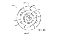
図10から図13を参照すると、アダプタ62は、バルブ54に連結されるとバルブ54を通る流れを可能にし、バルブ54から切り離されると流れを制限する。アダプタ62は、細長い流体通路66が内部を貫通する本体64を備える。締付要素68は、その上に突出したグリップ、ネジ、または突起69を有する。この締付要素68は、本体64の近位端に配置されて、バルブ54にアダプタ62を解放可能に連結し、軸方向にそれらを一緒に引っ張る。このような連結は、一般にルアーロック接続と呼ばれる。
Referring to FIGS. 10-13, the
作動ポスト70は、本体64の近位端で流体通路66に沿って位置する。作動ポスト70は、近位方向に締付要素68を超えて延びる。作動ポスト70は、バルブ54を貫通し、密封部材60を圧縮し、中空スパイクピン58を露出させるように構成され、これにより、バルブ54を開く。
アダプタ62は、作動ポスト70に結合され、かつ流体通路66と流体連通する再密封部材72を有する。好ましくは、再密封部材72は、弾性エラストマー材料で形成され、再密封部材72の弾性により通常は閉じているプレスリット開口74を有する。プレスリット開口74は、中空のスパイクピン58を受け入れるように構成され、バルブ54からの流体を流すためにアダプタ62を開く。プレスリット開口74は、バルブ54から離れると閉じ、これにより流体通路66から流出する流れを制限する。
ポート76は、本体64の遠位端に、流体通路66に沿って位置する。ポート76は、針のないシリンジ78にアダプタ62を流体接続するように構成される。針のないシリンジ78へのアダプタ62の接続を容易にするため、突出したグリップ、ネジ、または突起80は、本体64に備えられる。アダプタ62および針のないシリンジ78は、一体型構造で形成できることは、当業者には理解されるであろう。
図2、図8、図9、図12、および図13を参照すると、作動中、バイアル12は、開いた分離エンクロージャ14内に配置される。バイアル12を先行係合部材34に係合させることにより、第1の先行係合されるまたは固定される位置で、バイアル12は物質ハンドリングシステム10に固定される。バイアル12が固定されると、分離エンクロージャ14は閉じられる。
With reference to FIGS. 2, 8, 9, 12, and 13, during operation, the
代替方法では、係合抽出要素32は、分離エンクロージャ14とは別に設けられる。この場合、バイアル12は、分離エンクロージャ14の外側で先行係合部材34に最初に固定される。係合抽出要素32およびバイアル12が一緒に固定されると、それら係合抽出要素32およびバイアル12は、開いた分離エンクロージャ14内に置かれる。次に、係合抽出要素の接続部材52は、キャップ部分17の注入ポート18に取り付けられ、分離エンクロージャ14内にバイアル12を固定する。バイアル12が固定されると、分離エンクロージャ14は閉じられる。
In an alternative method, the
可撓性バッグ本体部分16を通してバイアルをつかみ、バイアル12を抽出部材36および主係合部材38に同時に係合させることにより、バイアル12を安全に穿刺できる。したがって、抽出部材36は、バイアル12を穿刺し、バイアル12へのアクセスを可能にする。主係合部材38は、抽出部材36にバイアル12を固定する。
The
一般に、この時点で希釈剤がバイアル12に追加される。これを達成するため、希釈剤を含む針のないシリンジ78が、アダプタ62に備えられる。アダプタ62は、バルブ54に嵌合され、中空のスパイクピン58およびプレスリット開口74の両方を開いて、流体を流す。希釈剤は、バイアル12に追加され、過剰ガスは、ベントポート48を通してバイアルから排出される。
In general, diluent is added to
希釈されると、バイアル12内容物の一部は、シリンジ78内に取り出される。アダプタ62およびシリンジ78は、バルブ54から切り離される。切り離されると、中空のスパイクピン58およびプレスリット開口74は、再密閉され、それぞれの内容物を別々に維持する。この時点で、バイアル12は、抽出部材36により穿孔された状態、および主係合部材38により固定された状態のままである。
When diluted, a portion of the contents of the
このとき、シリンジ78の内容物は、所望の移動先に移される。この移動は、分離エンクロージャ14から離れて位置する第2のバルブ54に、アダプタ62およびシリンジ78を取り外し可能に結合することによりなされる。再び、中空のスパイクピンおよびプレスリット開口74の両方が開き、第2のバルブ54内に流体が流れ込むことを可能にする。
At this time, the contents of the
したがって、本発明は、不透過性の分離エンクロージャ内にバイアルを固定できる方法および手段を提供することがわかる。本発明は、さらに、固定位置において不透過性の分離エンクロージャ内でバイアルを穿孔し、かつ選択的にバイアルの内容物にアクセスできる方法および手段を提供する。本発明は、また、バイアルが不透過性の分離エンクロージャ内で穿孔された状態である間に、バイアルの内容物一部を安全に移動できる方法および手段を提供する。 Thus, it can be seen that the present invention provides a method and means by which a vial can be secured within an impermeable separation enclosure. The present invention further provides a method and means for piercing a vial in an impermeable separation enclosure at a fixed location and selectively accessing the contents of the vial. The present invention also provides a method and means by which a portion of the contents of a vial can be safely moved while the vial is pierced within an impermeable separation enclosure.
したがって本発明は、少なくとも記載した目的の全てを達成することは明らかである。 It is therefore evident that the present invention achieves at least all of the stated objectives.
Claims (9)
本体部分と、バイアルに挿入されるように構成された本体部分の抽出部材と、本体部分に取り付けられた先行係合部材と、バイアルを抽出部材に対して固定するために本体部分に取り付けられた主係合部材とを備えており、先行係合部材が、本体部分から抽出部材と同一方向に延びる複数のラッチアームを含み、主係合部材が、本体部分から前記同一方向に延びる複数のラッチアームを含み、先行係合部材のラッチアームが、主係合部材のラッチアームよりも長い距離を本体部分から前記同一方向に延びている、ラッチ式抽出要素を準備するステップと、
不透過性の分離エンクロージャの選択的に密封可能な開口を通してバイアルを不透過性の分離エンクロージャの中に入れるステップと、
バイアルを先行係合部材のラッチアームの間に押し込んで係合させることにより、バイアルはラッチ式抽出要素に固定されるが抽出部材はバイアルの外側にある先行固定位置において、バイアルを固定するステップと、
ラッチ式抽出要素を不透過性の分離エンクロージャの内部に取り付けるステップと、
不透過性の分離エンクロージャの選択的に密封可能な開口を密封して閉じるステップと、
抽出部材がバイアルを突き刺すように、バイアルを主係合部材のラッチアームの間に押し込んで係合させることにより、主固定位置においてバイアルをラッチ式抽出要素に固定するステップと、
不透過性の分離エンクロージャの外側に取り付けられてラッチ式抽出要素の抽出部材と流体連通している通常は閉じられたバルブを介して、閉じられた不透過性の分離エンクロージャの外部からバイアルの内容物に選択的にアクセスするステップと、
バルブを通して針の無いシリンジの中にバイアルの内容物の少なくとも一部を取り出すステップと、
主固定位置においてバイアルを抽出部材で突き刺したままの状態で、バイアルから取り出した内容物の一部を分離して移動し、内容物の残った部分はバイアル内に分離して保持するステップと、
バイアルが抽出部材により突き刺された主固定位置にあり、かつ不透過性の分離エンクロージャが閉じられた状態で、バイアルに希釈剤を追加するステップとを備えており、
希釈剤を追加するステップが、抽出部材と本体部分との両方を貫通して、閉じられた不透過性の分離エンクロージャの内部のベントポートまで延びるベント流路を通して、バイアルからガスを排出することを含んでいる、前記方法。A method of accessing material in the sealed vial,
A body portion, a body portion extraction member configured to be inserted into the vial, a pre-engagement member attached to the body portion, and attached to the body portion to secure the vial to the extraction member A plurality of latch arms extending from the main body portion in the same direction as the extraction member, wherein the main engagement member extends from the main body portion in the same direction. Providing a latching extraction element including an arm, wherein the latch arm of the preceding engagement member extends from the body portion in the same direction at a greater distance than the latch arm of the main engagement member;
Placing the vial into the impermeable separation enclosure through a selectively sealable opening in the impermeable separation enclosure;
By engaging pushed between the latch arms of the prior engagement member vial, the vial is being The extraction member fixed to the latching extraction element is fixed fraud and mitigating risk vials prior fixed position on the outside of the vial Steps,
Mounting the latching extraction element inside an impermeable separating enclosure;
Sealing and closing the selectively sealable opening of the impermeable separation enclosure;
Securing the vial to the latching extraction element in the main securing position by pushing and engaging the vial between the latch arms of the main engagement member such that the extraction member pierces the vial;
The contents of the vial from the outside of the closed impermeable separation enclosure via a normally closed valve mounted outside the impermeable separation enclosure and in fluid communication with the extraction member of the latching extraction element Selectively accessing objects ,
Removing at least a portion of the contents of the vial through a valve into a needleless syringe;
Separating and moving a portion of the contents taken out of the vial while the vial remains pierced with the extraction member at the main fixing position, and separating and holding the remaining portion of the contents in the vial;
Adding a diluent to the vial with the vial in the main fixed position pierced by the extraction member and the impermeable separation enclosure closed.
The step of adding diluent is to expel the gas from the vial through a vent channel that extends through both the extraction member and the body portion to the vent port inside the closed impermeable separation enclosure. It is Nde including the method.
アダプタの第1の端部を、希釈剤を収容した針の無いシリンジに取り外し可能に結合し、アダプタの第2の端部は、希釈剤がシリンジから漏洩するのを制限するように、通常は閉じられている再密封部材によって密封された状態に維持されているサブステップと、The first end of the adapter is removably coupled to a syringe without a needle containing the diluent, and the second end of the adapter is typically used to limit leakage of the diluent from the syringe. A sub-step maintained in a sealed state by a closed reseal member;
アダプタの再密封部材とバルブとを開いて流体を流すように、アダプタの第2の端部を不透過性の分離エンクロージャのバルブに取り外し可能に結合するサブステップとを含んでいる、請求項1に記載の方法。And a sub-step of removably coupling the second end of the adapter to the valve of the impermeable isolation enclosure to open the reseal member of the adapter and the valve to allow fluid flow. The method described in 1.
バルブおよびアダプタの両方からの流体の流れを制限するように、アダプタの第2の端部をバルブから切り離すサブステップと、A sub-step of disconnecting the second end of the adapter from the valve so as to restrict fluid flow from both the valve and the adapter;
バイアルから取り出した内容物の一部の受渡しのために、シリンジを所望の移動先に移すサブステップと、A sub-step of moving the syringe to a desired destination for delivery of a portion of the contents removed from the vial;
アダプタの第2の端部を、不透過性の分離エンクロージャから離れた通常は閉じている第2のバルブに対して、取り外し可能に結合するサブステップとを含んでいる、請求項8に記載の方法。9. The substep of removably coupling the second end of the adapter to a normally closed second valve away from the impermeable isolation enclosure. Method.
Applications Claiming Priority (2)
| Application Number | Priority Date | Filing Date | Title |
|---|---|---|---|
| US10/453,393 US20040249235A1 (en) | 2003-06-03 | 2003-06-03 | Hazardous material handling system and method |
| PCT/US2004/017443 WO2004108058A2 (en) | 2003-06-03 | 2004-06-02 | Hazardous material handling system and method |
Publications (3)
| Publication Number | Publication Date |
|---|---|
| JP2006526477A JP2006526477A (en) | 2006-11-24 |
| JP2006526477A5 JP2006526477A5 (en) | 2007-07-12 |
| JP4664906B2 true JP4664906B2 (en) | 2011-04-06 |
Family
ID=33489533
Family Applications (1)
| Application Number | Title | Priority Date | Filing Date |
|---|---|---|---|
| JP2006515115A Expired - Fee Related JP4664906B2 (en) | 2003-06-03 | 2004-06-02 | Hazardous material handling system and method |
Country Status (6)
| Country | Link |
|---|---|
| US (2) | US20040249235A1 (en) |
| EP (1) | EP1633301A2 (en) |
| JP (1) | JP4664906B2 (en) |
| AU (1) | AU2004245055A1 (en) |
| CA (1) | CA2527924C (en) |
| WO (1) | WO2004108058A2 (en) |
Cited By (1)
| Publication number | Priority date | Publication date | Assignee | Title |
|---|---|---|---|---|
| TWI662209B (en) * | 2015-02-20 | 2019-06-11 | 瑞士商塞德爾斯 美島克斯公司 | Valve device, removing tool and mounting tool |
Families Citing this family (93)
| Publication number | Priority date | Publication date | Assignee | Title |
|---|---|---|---|---|
| DE202005010459U1 (en) * | 2004-11-22 | 2005-10-13 | Filtertek B.V., Newcastle West | Device for introducing air into containers used in artificial nutrition |
| US7648491B2 (en) | 2005-05-13 | 2010-01-19 | Bob Rogers | Medical substance transfer system |
| US20070016161A1 (en) * | 2005-06-13 | 2007-01-18 | Vasogen Ireland Limited | Controlled flow adapter with piercing end for medical fluid containers |
| AU2006279864A1 (en) * | 2005-08-12 | 2007-02-22 | Mallinckrodt Inc. | Radiation-shielding assembly having container location feature |
| US11478623B2 (en) * | 2006-02-09 | 2022-10-25 | Deka Products Limited Partnership | Infusion pump assembly |
| US7547300B2 (en) | 2006-04-12 | 2009-06-16 | Icu Medical, Inc. | Vial adaptor for regulating pressure |
| US20090306621A1 (en) * | 2008-02-06 | 2009-12-10 | Gale H. Thome, JR. | Vial transfer convenience IV kits and methods |
| US8449521B2 (en) * | 2008-02-06 | 2013-05-28 | Intravena, Llc | Methods for making and using a vial shielding convenience kit |
| WO2009140511A1 (en) | 2008-05-14 | 2009-11-19 | J&J Solutions, Inc. | Systems and methods for safe medicament transport |
| WO2010022095A1 (en) | 2008-08-20 | 2010-02-25 | Icu Medical, Inc. | Anti-reflux vial adaptors |
| CA3068441C (en) | 2009-07-29 | 2024-01-09 | Icu Medical, Inc. | Fluid transfer devices and methods of use |
| US9662271B2 (en) | 2009-10-23 | 2017-05-30 | Amgen Inc. | Vial adapter and system |
| EP2351596A1 (en) * | 2010-01-29 | 2011-08-03 | Fresenius Medical Care Deutschland GmbH | Insert for the infusion of drugs |
| WO2011091542A1 (en) * | 2010-02-01 | 2011-08-04 | Medmix Systems Ag | Device for removing a fluid from a vial |
| EP2959880B1 (en) | 2010-05-27 | 2017-04-12 | J&J Solutions, Inc. | Closed fluid transfer system |
| US9139316B2 (en) * | 2010-12-29 | 2015-09-22 | Cardinal Health 414, Llc | Closed vial fill system for aseptic dispensing |
| MX341790B (en) | 2011-03-31 | 2016-09-02 | Amgen Inc | Vial adapter and system. |
| CN103635215A (en) * | 2011-05-06 | 2014-03-12 | 赛诺菲-安万特德国有限公司 | Active valve for drug delivery |
| WO2013012822A1 (en) | 2011-07-15 | 2013-01-24 | Cardinal Health 414, Llc | Systems, methods, and devices for producing, manufacturing, and control of radiopharmaceuticals |
| CN104010616B (en) | 2011-08-18 | 2016-09-28 | Icu医学有限公司 | Controlled pressure type phial joint |
| EP4218857A3 (en) | 2011-12-22 | 2023-10-25 | ICU Medical, Inc. | Fluid transfer devices and methods of use |
| WO2013106757A1 (en) | 2012-01-13 | 2013-07-18 | Icu Medical, Inc. | Pressure-regulating vial adaptors and methods |
| CA3154910A1 (en) * | 2012-03-07 | 2013-09-12 | Deka Products Limited Partnership | Infusion pump assembly |
| AU2013204180B2 (en) | 2012-03-22 | 2016-07-21 | Icu Medical, Inc. | Pressure-regulating vial adaptors |
| EP3909639A1 (en) | 2012-03-27 | 2021-11-17 | Cytiva Sweden AB | Aseptic connector |
| IL221634A0 (en) | 2012-08-26 | 2012-12-31 | Medimop Medical Projects Ltd | Universal drug vial adapter |
| EP2948125B1 (en) | 2013-01-23 | 2019-05-22 | ICU Medical, Inc. | Pressure-regulating vial adaptors |
| US9089475B2 (en) | 2013-01-23 | 2015-07-28 | Icu Medical, Inc. | Pressure-regulating vial adaptors |
| US9414990B2 (en) | 2013-03-15 | 2016-08-16 | Becton Dickinson and Company Ltd. | Seal system for cannula |
| US9597260B2 (en) | 2013-03-15 | 2017-03-21 | Becton Dickinson and Company Ltd. | System for closed transfer of fluids |
| US20140283485A1 (en) * | 2013-03-19 | 2014-09-25 | Gale Harrison Thorne, JR. | Methods for making and using a vial shielding convenience kit |
| IL225734A0 (en) | 2013-04-14 | 2013-09-30 | Medimop Medical Projects Ltd | Ready-to-use drug vial assemblages including drug vial and drug vial closure having fluid transfer member, and drug vial closure therefor |
| CN105228676B (en) | 2013-05-10 | 2018-01-05 | 麦迪麦珀医疗工程有限公司 | Include the medical treatment device of the vial adapter with inline dry kit |
| CN105722493B (en) | 2013-07-19 | 2019-10-11 | 伊库医学有限公司 | Pressure adjusts fluid delivery system and method |
| NZ716552A (en) | 2013-08-02 | 2020-02-28 | J&J Solutions Inc D B A Corvida Medical | Compounding systems and methods for safe medicament transport |
| WO2015019343A1 (en) | 2013-08-07 | 2015-02-12 | Medimop Medical Projects Ltd | Liquid transfer devices for use with infusion liquid containers |
| EP3049044B1 (en) * | 2013-09-25 | 2022-06-15 | Saint-Gobain Performance Plastics Corporation | Cryopreservation container |
| US20150096646A1 (en) * | 2013-10-08 | 2015-04-09 | Stephanie Davidson | Needle-less vial assembly for use with needle-free system |
| JP2016535636A (en) | 2013-11-06 | 2016-11-17 | ベクトン ディキンソン アンド カンパニー リミテッド | Fluid closure transfer system with connector |
| CN106413799B (en) | 2013-11-06 | 2019-12-06 | 贝克顿·迪金森有限公司 | Liquid closed transfer system with locking mechanism |
| CA2929473C (en) | 2013-11-06 | 2019-06-04 | Becton Dickinson and Company Limited | Medical connector having locking engagement |
| WO2015069643A1 (en) | 2013-11-06 | 2015-05-14 | Becton Dickinson and Company Limited | Connection apparatus for a medical device |
| EP3073982B1 (en) | 2013-11-25 | 2020-04-08 | ICU Medical, Inc. | Methods and system for filling iv bags with therapeutic fluid |
| AU2015215683B2 (en) * | 2014-02-07 | 2019-08-22 | Industrie Borla S.P.A. | Access device for containers of fluidizable substances |
| USD794183S1 (en) | 2014-03-19 | 2017-08-08 | Medimop Medical Projects Ltd. | Dual ended liquid transfer spike |
| CA2945533C (en) | 2014-04-16 | 2018-10-16 | Becton Dickinson and Company Limited | Fluid transfer device with axially and rotationally movable portion |
| EP3134059B1 (en) | 2014-04-21 | 2020-03-04 | Becton Dickinson and Company Limited | Fluid transfer device and packaging therefor |
| JP6356828B2 (en) | 2014-04-21 | 2018-07-11 | ベクトン ディキンソン アンド カンパニー リミテッド | Fluid transfer device and packaging therefor |
| CN106413663B (en) | 2014-04-21 | 2019-02-12 | 贝克顿迪金森有限公司 | The syringe adapter being disengaged with compound motion |
| EP4233827A3 (en) | 2014-04-21 | 2023-11-01 | Becton Dickinson and Company Limited | System for closed transfer of fluids |
| EP3714861A1 (en) | 2014-04-21 | 2020-09-30 | Becton Dickinson and Company Limited | System for closed transfer of fluids and membrane arrangements for use thereof |
| JP6466967B2 (en) | 2014-04-21 | 2019-02-06 | ベクトン ディキンソン アンド カンパニー リミテッド | Syringe adapter with disconnect feedback mechanism |
| CA2946563C (en) | 2014-04-21 | 2019-03-12 | Becton Dickinson and Company Limited | Vial stabilizer base with connectable vial adapter |
| EP3134055B1 (en) | 2014-04-21 | 2018-06-27 | Becton Dickinson and Company Limited | System with adapter for closed transfer of fluids |
| CA2953229C (en) | 2014-06-20 | 2024-01-02 | Icu Medical, Inc. | Pressure-regulating vial adaptors |
| CN108601706B (en) | 2015-01-05 | 2019-06-25 | 麦迪麦珀医疗工程有限公司 | With for guaranteeing the vial adapter component of proper use of quick release vial adapter |
| CN107405445B (en) * | 2015-03-23 | 2020-10-09 | 株式会社Jms | Adapter |
| JP6367512B1 (en) | 2015-07-16 | 2018-08-01 | ウエスト・ファーマ.サービシーズ・イスラエル,リミテッド | Solution transfer device for securely snap-fitting into injection vials |
| JP6366876B1 (en) * | 2015-07-20 | 2018-08-01 | ウエスト・ファーマ.サービシーズ・イスラエル,リミテッド | Solution transfer device having set-up vial holding flexure |
| NZ740418A (en) | 2015-09-17 | 2022-02-25 | J&J Solutions Inc D B A Corvida Medical | Medicament vial assembly |
| JP2018530396A (en) | 2015-10-13 | 2018-10-18 | ジェイ アンド ジェイ ソリューションズ,インコーポレイテッド | Automatic compounding equipment for closed fluid transfer systems. |
| USD801522S1 (en) | 2015-11-09 | 2017-10-31 | Medimop Medical Projects Ltd. | Fluid transfer assembly |
| US10278897B2 (en) | 2015-11-25 | 2019-05-07 | West Pharma. Services IL, Ltd. | Dual vial adapter assemblage including drug vial adapter with self-sealing access valve |
| JP6710758B2 (en) | 2015-12-04 | 2020-06-17 | アイシーユー・メディカル・インコーポレーテッド | Electronic medical fluid transfer device for transferring medical fluid |
| IL243108B (en) * | 2015-12-22 | 2018-08-30 | Kriheli Marino | Connector section |
| WO2017132588A1 (en) | 2016-01-29 | 2017-08-03 | Icu Medical, Inc. | Pressure-regulating vial adaptors |
| IL245800A0 (en) | 2016-05-24 | 2016-08-31 | West Pharma Services Il Ltd | Dual vial adapter assemblages including identical twin vial adapters |
| IL245803A0 (en) | 2016-05-24 | 2016-08-31 | West Pharma Services Il Ltd | Dual vial adapter assemblages including vented drug vial adapter and vented liquid vial adapter |
| CA3025593A1 (en) * | 2016-06-03 | 2017-12-07 | Teva Medical Ltd. | A shielding device for manipulating a radioactive solution |
| IL246073A0 (en) | 2016-06-06 | 2016-08-31 | West Pharma Services Il Ltd | Fluid transfer devices for use with drug pump cartridge having slidable driving plunger |
| USD851745S1 (en) | 2016-07-19 | 2019-06-18 | Icu Medical, Inc. | Medical fluid transfer system |
| WO2018022640A1 (en) | 2016-07-25 | 2018-02-01 | Icu Medical, Inc. | Systems, methods, and components for trapping air bubbles in medical fluid transfer modules and systems |
| IL247376A0 (en) | 2016-08-21 | 2016-12-29 | Medimop Medical Projects Ltd | Syringe assembly |
| WO2018064206A1 (en) | 2016-09-30 | 2018-04-05 | Icu Medical, Inc. | Pressure-regulating vial access devices and methods |
| USD832430S1 (en) | 2016-11-15 | 2018-10-30 | West Pharma. Services IL, Ltd. | Dual vial adapter assemblage |
| IL249408A0 (en) | 2016-12-06 | 2017-03-30 | Medimop Medical Projects Ltd | Liquid transfer device for use with infusion liquid container and pincers-like hand tool for use therewith for releasing intact drug vial therefrom |
| US11197803B2 (en) * | 2017-03-24 | 2021-12-14 | Carefusion 303, Inc. | Needleless cartridge for automatic drug compounder |
| IL251458A0 (en) | 2017-03-29 | 2017-06-29 | Medimop Medical Projects Ltd | User actuated liquid drug transfer devices for use in ready-to-use (rtu) liquid drug transfer assemblages |
| JP6972747B2 (en) * | 2017-08-03 | 2021-11-24 | 株式会社ジェイ・エム・エス | Adapter assembly |
| IL254802A0 (en) | 2017-09-29 | 2017-12-31 | Medimop Medical Projects Ltd | Dual vial adapter assemblages with twin vented female vial adapters |
| JP1630477S (en) | 2018-07-06 | 2019-05-07 | ||
| USD923812S1 (en) | 2019-01-16 | 2021-06-29 | West Pharma. Services IL, Ltd. | Medication mixing apparatus |
| JP1648075S (en) | 2019-01-17 | 2019-12-16 | ||
| US11918542B2 (en) | 2019-01-31 | 2024-03-05 | West Pharma. Services IL, Ltd. | Liquid transfer device |
| AU2020265821B2 (en) | 2019-04-30 | 2023-07-20 | West Pharma. Services IL, Ltd. | Liquid transfer device with dual lumen IV spike |
| USD957630S1 (en) | 2019-05-20 | 2022-07-12 | Icu Medical, Inc. | Port retention clip |
| USD931441S1 (en) | 2019-05-20 | 2021-09-21 | Icu Medical, Inc. | Port retention clip |
| USD930824S1 (en) | 2019-05-20 | 2021-09-14 | Icu Medical, Inc. | Port retention clip |
| US11590057B2 (en) | 2020-04-03 | 2023-02-28 | Icu Medical, Inc. | Systems, methods, and components for transferring medical fluids |
| US11612733B2 (en) * | 2020-04-23 | 2023-03-28 | Carefusion 303, Inc. | Screw control medical fluid flow manifolds |
| USD956958S1 (en) | 2020-07-13 | 2022-07-05 | West Pharma. Services IL, Ltd. | Liquid transfer device |
| JP2023546374A (en) | 2020-10-09 | 2023-11-02 | アイシーユー・メディカル・インコーポレーテッド | Fluid transfer device and method of use therefor |
| EP4112035A1 (en) * | 2021-06-29 | 2023-01-04 | Kairish Innotech Private Ltd. | Tray for positioning a medical vial together with a vial adapter in a fixed positional relationship relative to each other and packaging unit comprising the same |
Citations (4)
| Publication number | Priority date | Publication date | Assignee | Title |
|---|---|---|---|---|
| JPH021277A (en) * | 1988-03-31 | 1990-01-05 | Fujisawa Pharmaceut Co Ltd | Infusion container |
| JPH0670737U (en) * | 1993-03-25 | 1994-10-04 | 昭和電工株式会社 | Infusion container |
| JPH08257101A (en) * | 1995-03-22 | 1996-10-08 | Nissho Corp | Dissolution liquid injection set |
| JPH08308905A (en) * | 1995-05-23 | 1996-11-26 | Showa Denko Kk | Infusion container |
Family Cites Families (32)
| Publication number | Priority date | Publication date | Assignee | Title |
|---|---|---|---|---|
| FR1417152A (en) | 1964-07-22 | 1965-11-12 | Sames Mach Electrostat | Product for the treatment of agricultural crops and means for its preparation |
| US3940003A (en) * | 1974-05-07 | 1976-02-24 | Pharmaco, Inc. | Safety cap for medicament vial having puncturable seal |
| US4401432A (en) | 1982-05-26 | 1983-08-30 | Boris Schwartz | Storage, mixing and filtering receptacle for syringe |
| SE434700B (en) | 1983-05-20 | 1984-08-13 | Bengt Gustavsson | DEVICE FOR AIRED TRANSFER OF SUBSTANCE FROM A KERLE TO ANOTHER |
| EP0165926B1 (en) * | 1983-05-20 | 1990-10-24 | Bengt Gustavsson | A device for transferring a substance |
| SE442264B (en) | 1983-12-23 | 1985-12-16 | Bengt Gustavsson | AMPOULE |
| US4645073A (en) | 1985-04-02 | 1987-02-24 | Survival Technology, Inc. | Anti-contamination hazardous material package |
| US4722733A (en) | 1986-02-26 | 1988-02-02 | Intelligent Medicine, Inc. | Drug handling apparatus and method |
| EP0273015A3 (en) * | 1986-12-24 | 1988-10-05 | Vifor S.A. | Container with a receiving device for a vial |
| EP0354947B1 (en) | 1988-01-25 | 1994-07-20 | BAXTER INTERNATIONAL INC. (a Delaware corporation) | Pre-slit injection site and tapered cannula |
| FR2684007B1 (en) | 1991-11-25 | 1997-04-18 | Vygon | MONOBLOCK CONNECTOR WITH INTERNAL INJECTION NEEDLE FOR CONNECTING A LIQUID CIRCUIT, ESPECIALLY FOR MEDICAL APPLICATIONS. |
| US5195980A (en) | 1992-01-03 | 1993-03-23 | Thomas Medical Products, Inc. | Hemostatic valve |
| JPH0670737A (en) | 1992-08-24 | 1994-03-15 | Japan Tobacco Inc | Sampler of machine for producing cigarette with filter |
| US5405333A (en) * | 1992-12-28 | 1995-04-11 | Richmond; Frank M. | Liquid medicament bag with needleless connector fitting using boat assembly |
| WO1994023775A1 (en) * | 1993-03-23 | 1994-10-27 | Abbott Laboratories | Securing collar for cannula connector |
| US5833674A (en) * | 1993-08-27 | 1998-11-10 | St. Paul Medical, Inc. | Needleless IV medical delivery system |
| US5403293A (en) | 1994-01-03 | 1995-04-04 | Abbott Laboratories | Molded partial pre-slit reseal |
| US5470319A (en) * | 1994-06-20 | 1995-11-28 | Critical Device Corporation | Needleless injection site |
| US5509912A (en) * | 1994-10-24 | 1996-04-23 | Vlv Associates | Connector |
| US5492147A (en) * | 1995-01-17 | 1996-02-20 | Aeroquip Corporation | Dry break coupling |
| SE509950C2 (en) | 1995-05-02 | 1999-03-29 | Carmel Pharma Ab | Device for the administration of toxic liquid |
| US5848997A (en) * | 1996-03-15 | 1998-12-15 | Becton Dickinson And Company | Disconnect for medical access devices |
| GB9700177D0 (en) * | 1997-01-07 | 1997-02-26 | Nycomed Imaging As | Container |
| US6290682B1 (en) * | 1997-02-13 | 2001-09-18 | Filterek Inc. | Infusion set |
| GB2328432A (en) | 1997-08-23 | 1999-02-24 | Nmt Group Plc | Vial |
| IT236233Y1 (en) * | 1997-11-26 | 2000-08-08 | Eurospital S P A | DEVICE FOR THE CONNECTION OF A PHARMACEUTICAL PRODUCT CONTAINER TO A BAG OF LIQUID PRODUCT TO CARRY OUT THE |
| FR2773735B1 (en) | 1998-01-20 | 2000-02-25 | Becton Dickinson France | WATERPROOF CONTAINMENT DEVICE |
| US6096011A (en) * | 1998-01-29 | 2000-08-01 | Medrad, Inc. | Aseptic connector and fluid delivery system using such an aseptic connector |
| ES2325466T3 (en) * | 1998-05-29 | 2009-09-04 | Lawrence A. Lynn | LUER RECEIVER AND METHOD FOR THE TRANSFER OF FLUIDS. |
| SE513225C2 (en) | 1998-12-03 | 2000-08-07 | Carmel Pharma Ab | Arrangement, procedure and gas container for sterile or aseptic handling |
| DE19938078A1 (en) | 1999-08-12 | 2001-02-15 | Transcoject Gmbh | Unit for taking a liquid medicament from a container provided with a membrane comprises a movable housing section with a hollow mandrel which in a certain position pierces the membrane |
| US6745998B2 (en) * | 2001-08-10 | 2004-06-08 | Alaris Medical Systems, Inc. | Valved male luer |
-
2003
- 2003-06-03 US US10/453,393 patent/US20040249235A1/en not_active Abandoned
-
2004
- 2004-06-02 AU AU2004245055A patent/AU2004245055A1/en not_active Abandoned
- 2004-06-02 JP JP2006515115A patent/JP4664906B2/en not_active Expired - Fee Related
- 2004-06-02 EP EP20040754122 patent/EP1633301A2/en not_active Withdrawn
- 2004-06-02 CA CA 2527924 patent/CA2527924C/en not_active Expired - Fee Related
- 2004-06-02 WO PCT/US2004/017443 patent/WO2004108058A2/en active Application Filing
-
2006
- 2006-07-21 US US11/490,903 patent/US7758560B2/en not_active Expired - Fee Related
Patent Citations (4)
| Publication number | Priority date | Publication date | Assignee | Title |
|---|---|---|---|---|
| JPH021277A (en) * | 1988-03-31 | 1990-01-05 | Fujisawa Pharmaceut Co Ltd | Infusion container |
| JPH0670737U (en) * | 1993-03-25 | 1994-10-04 | 昭和電工株式会社 | Infusion container |
| JPH08257101A (en) * | 1995-03-22 | 1996-10-08 | Nissho Corp | Dissolution liquid injection set |
| JPH08308905A (en) * | 1995-05-23 | 1996-11-26 | Showa Denko Kk | Infusion container |
Cited By (1)
| Publication number | Priority date | Publication date | Assignee | Title |
|---|---|---|---|---|
| TWI662209B (en) * | 2015-02-20 | 2019-06-11 | 瑞士商塞德爾斯 美島克斯公司 | Valve device, removing tool and mounting tool |
Also Published As
| Publication number | Publication date |
|---|---|
| CA2527924A1 (en) | 2004-12-16 |
| US20040249235A1 (en) | 2004-12-09 |
| CA2527924C (en) | 2013-04-09 |
| EP1633301A2 (en) | 2006-03-15 |
| US20060259004A1 (en) | 2006-11-16 |
| WO2004108058A2 (en) | 2004-12-16 |
| AU2004245055A1 (en) | 2004-12-16 |
| US7758560B2 (en) | 2010-07-20 |
| JP2006526477A (en) | 2006-11-24 |
| WO2004108058A3 (en) | 2005-02-24 |
Similar Documents
| Publication | Publication Date | Title |
|---|---|---|
| JP4664906B2 (en) | Hazardous material handling system and method | |
| US10806668B2 (en) | Method and assembly for fluid transfer and drug containment in an infusion system | |
| KR101507828B1 (en) | Method and apparatus for contamination-free transfer of a hazardous drug | |
| JP6371369B2 (en) | System for closed transfer of fluid | |
| JP5023070B2 (en) | A vial adapter that is ventilated and can be handled safely. | |
| JP4731118B2 (en) | Fluid transfer method and apparatus in infusion system | |
| US7744581B2 (en) | Device and method for mixing medical fluids | |
| CA2650966C (en) | Vented infusion access device | |
| JP2007509691A5 (en) | ||
| WO2007148708A1 (en) | Liquid medicine preparation kit | |
| JP7442568B2 (en) | Syringe adapter with suction assembly | |
| KR101996378B1 (en) | Device for interfacing a fluid injection instrument with a puncturable flask and method for use thereof | |
| WO2023031910A1 (en) | Closed system for sterile drug preparation and administration |
Legal Events
| Date | Code | Title | Description |
|---|---|---|---|
| A521 | Written amendment |
Free format text: JAPANESE INTERMEDIATE CODE: A523 Effective date: 20070524 |
|
| A621 | Written request for application examination |
Free format text: JAPANESE INTERMEDIATE CODE: A621 Effective date: 20070524 |
|
| A131 | Notification of reasons for refusal |
Free format text: JAPANESE INTERMEDIATE CODE: A131 Effective date: 20100126 |
|
| A601 | Written request for extension of time |
Free format text: JAPANESE INTERMEDIATE CODE: A601 Effective date: 20100423 |
|
| A602 | Written permission of extension of time |
Free format text: JAPANESE INTERMEDIATE CODE: A602 Effective date: 20100506 |
|
| A521 | Written amendment |
Free format text: JAPANESE INTERMEDIATE CODE: A523 Effective date: 20100723 |
|
| TRDD | Decision of grant or rejection written | ||
| A01 | Written decision to grant a patent or to grant a registration (utility model) |
Free format text: JAPANESE INTERMEDIATE CODE: A01 Effective date: 20101214 |
|
| A01 | Written decision to grant a patent or to grant a registration (utility model) |
Free format text: JAPANESE INTERMEDIATE CODE: A01 |
|
| A61 | First payment of annual fees (during grant procedure) |
Free format text: JAPANESE INTERMEDIATE CODE: A61 Effective date: 20110107 |
|
| R150 | Certificate of patent or registration of utility model |
Free format text: JAPANESE INTERMEDIATE CODE: R150 |
|
| FPAY | Renewal fee payment (event date is renewal date of database) |
Free format text: PAYMENT UNTIL: 20140114 Year of fee payment: 3 |
|
| LAPS | Cancellation because of no payment of annual fees |