JP4664898B2 - Telescopic actuator for vehicles - Google Patents
Telescopic actuator for vehicles Download PDFInfo
- Publication number
- JP4664898B2 JP4664898B2 JP2006352932A JP2006352932A JP4664898B2 JP 4664898 B2 JP4664898 B2 JP 4664898B2 JP 2006352932 A JP2006352932 A JP 2006352932A JP 2006352932 A JP2006352932 A JP 2006352932A JP 4664898 B2 JP4664898 B2 JP 4664898B2
- Authority
- JP
- Japan
- Prior art keywords
- screw member
- female screw
- male screw
- vehicle
- housing
- Prior art date
- Legal status (The legal status is an assumption and is not a legal conclusion. Google has not performed a legal analysis and makes no representation as to the accuracy of the status listed.)
- Expired - Fee Related
Links
Images


Description
本発明は、相互に螺合する雄ねじ部材および雌ねじ部材をモータで相対回転させ、前記雄ねじ部材および前記雌ねじ部材の軸方向の相対変位をスラスト力として出力する車両用伸縮アクチュエータに関する。 The present invention relates to a telescopic actuator for a vehicle that rotates a male screw member and a female screw member that are screwed to each other with a motor and outputs a relative displacement in the axial direction of the male screw member and the female screw member as a thrust force.
車両のサスペンション装置のアッパーリンクおよびロアリンクをアクチュエータで伸縮制御することで、車輪のバンプおよびリバウンドに伴うキャンバー角や対地トレッドの変化を抑制して操縦安定性能を高めるものにおいて、前記アクチュエータをモータで相対回転する雄ねじ部材および雌ねじ部材を備えた送りねじ機構で構成したものが、下記特許文献1により公知である。
ところで、送りねじ機構を用いたこの種のアクチュエータでは、相対回転する雄ねじ部材および雌ねじ部材間に微小なバックラッシュが存在するため、出力側から逆伝達される振動的な荷重や大きな荷重によって雄ねじ部材および雌ねじ部材がスリップして相対回転してしまい、アクチュエータが意図しない伸縮をする可能性があった。これを防止するには、モータに雄ねじ部材および雌ねじ部材の相対回転を規制する保持トルクを発生させれば良いが、このようにするとモータの消費電力が増加してしまうという新たな問題が発生する。 By the way, in this type of actuator using a feed screw mechanism, since there is a minute backlash between the male screw member and the female screw member that rotate relative to each other, the male screw member is caused by a vibration load or a large load that is reversely transmitted from the output side. In addition, the female screw member slips and rotates relatively, and the actuator may expand and contract unintentionally. In order to prevent this, it is only necessary to generate a holding torque that restricts the relative rotation of the male screw member and the female screw member in the motor. However, this causes a new problem that the power consumption of the motor increases. .
本発明は前述の事情に鑑みてなされたもので、送りねじ機構を用いた、トー角制御のための車両用伸縮アクチュエータが外力により伸縮するのを機械的に規制することを目的とする。 The present invention has been made in view of the above circumstances, and an object of the present invention is to mechanically restrict the expansion / contraction of a vehicular expansion / contraction actuator for toe angle control that uses a feed screw mechanism due to external force.
上記目的を達成するために、請求項1に記載された発明によれば、車輪を回転自在に支持するナックルと、そのナックルを上下動可能に車体に連結するアームとを備えた車両に装備されて、伸縮変位により前記車輪のトー角を制御すべく前記アームとは別に前記ナックルを車体に連結する車両用伸縮アクチュエータであって、相互に螺合する雄ねじ部材および雌ねじ部材をモータで相対回転させ、前記雄ねじ部材および前記雌ねじ部材の軸方向の相対変位をスラスト力として出力するものにおいて、前記雄ねじ部材および前記雌ねじ部材の一方を他方に向けて軸方向に付勢することで前記雄ねじ部材および前記雌ねじ部材のねじ山相互を常に密着させて両ねじ部材間に摩擦力を発生させる弾性体を備え、その弾性体は、前記車輪側から前記雄ねじ部材および前記雌ねじ部材の一方に荷重が入力したときに両ねじ部材の相対回転を防ぐ前記摩擦力を発生させる弾発力を有していることを特徴とする車両用伸縮アクチュエータが提案される。 In order to achieve the above object, according to the invention described in claim 1, the vehicle is equipped with a knuckle that rotatably supports a wheel and an arm that connects the knuckle to the vehicle body so as to be movable up and down. A telescopic actuator for a vehicle that connects the knuckle to the vehicle body separately from the arm to control the toe angle of the wheel by expansion / contraction displacement, and a male screw member and a female screw member that are screwed together are relatively rotated by a motor. The axial displacement of the male screw member and the female screw member is output as a thrust force. By biasing one of the male screw member and the female screw member in the axial direction toward the other, the male screw member and the an elastic member which generates a frictional force between the two threaded members is always brought into close contact with the threads cross of the female screw member, the elastic member, the male from the wheel side Expansion actuators is proposed a vehicle, characterized in that it has a resilient force causing the frictional force preventing relative rotation of the two threaded members when Flip load on one member and the female screw member is entered .
また請求項2に記載された発明によれば、請求項1の構成に加えて、前記雌ねじ部材を軸方向に分割された複数の要素で構成し、前記複数の要素の相互間に前記弾性体を焼き付けにより固定して、その弾性体の予荷重で前記複数の要素を相互に離反する方向に付勢することを特徴とする車両用伸縮アクチュエータが提案される。
According to the invention described in
尚、実施の形態のコイルばね101、ゴムブッシュ111および皿ばね112は本発明の弾性体に対応する。
In addition, the
請求項1の構成によれば、相互に螺合する雄ねじ部材および雌ねじ部材をモータで相対回転させると、雄ねじ部材および雌ねじ部材の軸方向の相対変位をスラスト力として出力することができる。特に車輪側から振動的な荷重や大きな荷重が入力すると、雄ねじ部材および雌ねじ部材がスリップにより相対回転して伸縮アクチュエータが意図せぬ伸縮を行う可能性があるが、雄ねじ部材および雌ねじ部材の一方を他方に向けて軸方向に付勢することで両ねじ部材のねじ山相互を常に密着させて摩擦力を発生させる弾性体を備え、その弾性体が、車輪側から一方のねじ部材に荷重が入力したときに両ねじ部材の相対回転を防ぐ前記摩擦力を発生させる弾発力を有しているので、雄ねじ部材および雌ねじ部材間に、その間の相対回転を抑制し得る摩擦力を発生させて両ねじ部材の相対回転を抑制でき、従って前記意図せぬ伸縮の発生を防止できて、車輪のトー角が変化するのを防止することができるため、車輪のトー角の制御精度が向上する。しかも、モータに電流を流してねじ部材の意図せぬ回転を抑制する必要はなくなり、モータの消費電力が削減される。 According to the configuration of the first aspect, when the male screw member and the female screw member that are screwed together are relatively rotated by the motor, the axial relative displacement of the male screw member and the female screw member can be output as a thrust force. Especially when the vibration load or large load from the wheel side to the input, but the externally threaded member and the internally threaded member is likely to perform stretching, not relative rotational expansion actuators is unintentionally by slip, one of the male threaded member and the internally threaded member Is provided with an elastic body that always causes the screw threads of both screw members to closely adhere to each other to generate a frictional force, and that elastic body applies a load to one screw member from the wheel side. Since it has a resilient force to generate the frictional force that prevents relative rotation of both screw members when input, a frictional force that can suppress relative rotation between the male screw member and the female screw member is generated. both screws can be suppressed relative rotation member, thus it can be prevented the occurrence of stretch which is not the intention, since the toe angles of the wheel can be prevented from changing to improve the control accuracy of the toe angle of the wheel In addition, it is not necessary to flow an electric current through the motor to suppress unintended rotation of the screw member, and the power consumption of the motor is reduced.
また請求項2の構成によれば、雌ねじ部材を軸方向に分割した複数の要素を弾性体の予荷重で相互に離反する方向に付勢するので、雌ねじ部材の各要素と雄ねじ部材との間に摩擦力を発生させることができる。しかも雌ねじ部材の各要素は相互に相対回転しないため、弾性体の捩じれを防止する手段が不要になって構造が簡素化される。 According to the second aspect of the present invention, since the plurality of elements obtained by dividing the female screw member in the axial direction are biased in a direction away from each other by the preload of the elastic body, between each element of the female screw member and the male screw member A frictional force can be generated. Moreover each element of the female screw member because it does not rotate relative to each other, the structure is Ru is simplified means for preventing twisting of the elastic body becomes unnecessary.
以下、本発明の実施の形態を添付の図面に基づいて説明する。 Hereinafter, embodiments of the present invention will be described with reference to the accompanying drawings.
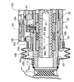
図1〜図7は本発明の第1の実施の形態を示すもので、図1は左後輪のサスペンション装置の斜視図、図2は図1の2方向矢視図、図3はトーコントロールアクチュエータの縦断面図、図4は図3の4部拡大図、図5は図3の5部拡大図、図6は減速機およびカップリングの分解斜視図、図7は図3の7−7線拡大断面図である。
1 to 7 show a first embodiment of the present invention. FIG. 1 is a perspective view of a left rear wheel suspension device, FIG. 2 is a view in the direction of the
図1および図2に示すように、四輪操舵車両のダブルウイッシュボーン式のリヤサスペンションSは、後輪Wを回転自在に支持するナックル11と、ナックル11を上下動可能に車体に連結するアッパーアーム12およびロアアーム13と、後輪Wのトー角を制御すべくナックル11および車体を連結するトーコントロールアクチュエータ14と、後輪Wの上下動を緩衝する懸架ばね付きダンパー15等で構成される。
As shown in FIGS. 1 and 2, a double wishbone type rear suspension S for a four-wheel steering vehicle includes a
基端をそれぞれゴムブッシュジョイント16,17で車体に連結されたアッパーアーム12およびロアアーム13の先端は、それぞれボールジョイント18,19を介してナックル11の上部および下部に連結される。トーコントロールアクチュエータ14は、基端がゴムブッシュジョイント20を介して車体に連結され、先端がゴムブッシュジョイント21を介してナックル11の後部に連結される。上端を車体(サスペンションタワーの上壁22)に固定された懸架ばね付きダンパー15の下端が、ゴムブッシュジョイント23を介してナックル11の上部に連結される。
The distal ends of the
トーコントロールアクチュエータ14を伸長駆動すると、ナックル11の後部が車幅方向外側に押されて後輪Wのトー角がトーイン方向に変化し、トーコントロールアクチュエータ14を収縮駆動すると、ナックル11の後部が車幅方向内側に引かれて後輪Wのトー角がトーアウト方向に変化する。従って、ステアリングホイールの操作による通常の前輪の操舵に加えて、車速やステアリングホイールの操舵角に応じて後輪Wのトー角を制御することで、車両の直進安定性能や旋回性能を高めることができる。
When the
次に、図3〜図7に基づいてトーコントロールアクチュエータ14の構造を詳細に説明する。
Next, the structure of the
図3および図4に示すように、トーコントロールアクチュエータ14は、車体側に連結されるゴムブッシュジョイント20が一体に設けられた第1ハウジング31と、ナックル11側に連結されるゴムブッシュジョイント21が一体に設けられた出力ロッド33を伸縮自在に支持する第2ハウジング32とを備えており、第1、第2ハウジング31,32の対向部は、シール部材34を介してインロー嵌合した状態で、各々の結合フランジ31a,32aを複数本のボルト35…で締結して一体化される。第1ハウジング31の内部には駆動源となるブラシ付きのモータ36が収納され、第2ハウジング32の内部には遊星歯車式の減速機37と、弾性を有するカップリング38と、台形ねじを用いた送りねじ機構39とが収納される。
As shown in FIGS. 3 and 4, the
このように、モータ36を収納する第1ハウジング31と、減速機37、カップリング38および送りねじ機構39を収納する第2ハウジング32とを予めサブアセンブリ化しておき、それらを結合することでトーコントロールアクチュエータ14を構成するので、モータ36を出力の大きいものや小さいものに変更したい場合や、減速機37や送りねじ機構39の作動特性を変更したい場合に、トーコントロールアクチュエータ14全体を設計変更することなく、第1ハウジング31側のサブアセンブリあるいは第2ハウジング32側のサブアセンブリだけの交換で対応することが可能となり、多機種に対する汎用性が向上してコストダウンが可能になる。
As described above, the
モータ36の外郭は、フランジ40aを有するをカップ状に形成されたヨーク40と、ヨーク40のフランジ40aに複数のボルト41…で締結されたベアリングホルダ42とで構成される。ヨーク40およびベアリングホルダ42を締結するボルト41…は第1ハウジング31の端面に螺合しており、このボルト41…を利用してモータ36が第1ハウジング31に固定される。
The outer shell of the
ヨーク40の内周面に支持した環状のステータ43内に配置されるロータ44は、その回転軸45の一端がヨーク40の底部に設けたボールベアリング46に回転自在に支持され、他端がベアリングホルダ42に設けたボールベアリング47に回転自在に支持される。ベアリングホルダ42の内面には、回転軸45の外周に設けたコミュテータ48に摺接するブラシ49が支持される。ブラシ49から延びる導線50は、第1ハウジング31に設けたグロメット51を介して外部に引き出される。
The
ステータ43およびロータ44を収納する強固な部品であるヨーク40でモータ36の外郭を構成し、このヨーク40を第1ハウジング31に固定したので、後輪Wからトーコントロールアクチュエータ14に入力される荷重を第1ハウジング31で受けてモータ36に作用し難くし、モータ36の耐久性や信頼性を高めることができる。しかもモータ36のヨーク40の外周面と第1ハウジング31の内周面との間に隙間αが形成されているため、この隙間αによりモータ36の作動音が第1ハウジング31の外部に漏れるのを抑制することができるだけでなく、第1ハウジング31に作用する外力がモータ36に伝達されるのを更に確実に防止することができる。
The
またモータ36のヨーク40およびベアリングホルダ42を一体に締結するボルト41…を利用してモータ36を第1ハウジング31に固定するので、前記ボルト41…とは別のボルトでモータ36を第1ハウジング31に固定する場合に比べて、ボルトの本数を削減できるだけでなく、前記別のボルトを配置するスペースを削減してトーコントロールアクチュエータ14の小型化を図ることができる。
In addition, the
図4および図5に示すように、減速機37は第1遊星歯車機構61および第2遊星歯車機構62を2段に結合して構成される。第1遊星歯車機構61は、第2ハウジング32の開口部に嵌合して固定されたリングギヤ63と、モータ36の回転軸45の先端に直接形成された第1サンギヤ64と、円板状の第1キャリヤ65と、第1キャリヤ65に圧入により片持ち支持された第1ピニオンピン66…にボールベアリング67…を介して回転自在に支持され、前記リングギヤ63および前記第1サンギヤ64に同時に噛合する4個の第1ピニオン68…とで構成される。第1遊星歯車機構61は、入力部材である第1サンギヤ64の回転を、出力部材である第1キャリヤ65に減速して伝達する。
As shown in FIGS. 4 and 5, the
減速機37の第2遊星歯車機構62は、第1遊星歯車機構61と共通のリングギヤ63と、第1キャリヤ65の中心に固定された第2サンギヤ69と、円板状の第2キャリヤ70と、第2キャリヤ70に圧入により片持ち支持された第2ピニオンピン71…にスライドブッシュ72…を介して回転自在に支持され、前記リングギヤ63および前記第2サンギヤ69に同時に噛合する4個の第2ピニオン73…とで構成される。第2遊星歯車機構62は、入力部材である第2サンギヤ69の回転を、出力部材である第2キャリヤ70に減速して伝達する。
The second
このように第1、第2遊星歯車機構61,62を直列に接続することで、大きな減速比を得ることができ、しかも減速機37の小型化を図ることができる。また第1遊星歯車機構61のサンギヤ64を、モータ36の回転軸45に固定することなく回転軸45に直接形成したので、回転軸45と別体の第1サンギヤ64を用いる場合に比べて部品点数を削減することができるだけでなく、第1サンギヤ64の直径を最小限に抑えて第1遊星歯車機構61の減速比を大きく設定することができる。
Thus, by connecting the first and second
減速機37の出力部材である第2キャリヤ70は、送りねじ機構39の入力部材である入力フランジ74にカップリンング38を介して接続される。概ね円板状の入力フランジ74は、その外周部を一対のスラストベアリング75,76に挟まれて回転自在に支持される。即ち、第2ハウジング32の内周面にスペーサカラー77を挟むように環状のロックナット78が締結されており、一方のスラストベアリング75は第2ハウジング32と入力フランジ74との間のスラスト荷重を支持し、他方のスラストベアリング76はロックナット78と入力フランジ74との間のスラスト荷重を支持するように配置される。
The
図4、図6および図7から明らかなように、カップリング38は、例えばポリアセタールで構成された2枚の外側弾性ブッシュ79,79と、例えばシリコンゴムで構成された1枚の内側弾性ブッシュ80とを備えており、それらの外周には各8個の突起79a…,80a…および各8個の溝79b…,80b…が等間隔で放射状に突出する。一方、第2キャリヤ70および入力フランジ74の対向面には、各4個の爪70a…,74a…が等間隔で軸方向に対峙するように突出する。
4, 6, and 7, the
外側弾性ブッシュ79,79および内側弾性ブッシュ80は突起79a…,80a…の位相が揃うように重ね合わされ、8個の溝79b…,80b…のうちの一つおきの4個に第2キャリヤ70の4個の爪70a…が係合し、8個の溝79b…,80b…のうちの残りの4個に入力フランジ74の4個の爪74a…が係合する。
The outer
従って、第2キャリヤ70のトルクは、該第2キャリヤ70の爪70a…から外側弾性ブッシュ79,79および内側弾性ブッシュ80は突起79a…,80a…と、入力フランジ74の爪74a…とを介して、該入力フランジ74に伝達される。その際に、弾性体で構成された外側弾性ブッシュ79,79および内側弾性ブッシュ80が、第2キャリヤ70および入力フランジ74間の微小な軸線のずれを吸収するとともに、トルクの急変を吸収してスムーズな動力伝達を可能にすることができる。
Accordingly, the torque of the
図5から明らかなように、第2ハウジング32の軸方向中間部の内周面に第1スライドベアリング91が固定され、また第1ハウジング32の軸方向端部に螺合するエンド部材93の内周面に第2スライドベアリング92が固定されており、これら第1、第2スライドベアリング91,92に前記出力ロッド33が摺動自在に支持される。入力フランジ74の回転運動を出力ロッド33のスラスト運動に変換する送りねじ機構39は、入力フランジ74の中心を貫通してナット94(図4参照)で締結された雄ねじ部材95と、この雄ねじ部材95の外周に螺合するとともに、中空の出力ロッド33の内周面に嵌合してロックナット97で固定された雌ねじ部材96とを備える。
As is clear from FIG. 5, the first slide bearing 91 is fixed to the inner peripheral surface of the axially intermediate portion of the
このように、出力ロッド33を複数個(実施の形態では2個)のスライドベアリング91,92を介して第2ハウジング32に支持したので、出力ロッド33に加わる径方向の荷重を第2ハウジング32で確実に支持して送りねじ機構39のコジリを防止することができる。
As described above, since the
雄ねじ部材95の先端にスラストベアリング98を介して支持したばね座99と、出力ロッド33の先端に設けたばね座100との間に、コイルばね101が縮設される。このコイルばね101の弾発力は、出力ロッド33に固定された雌ねじ部材96と、この雌ねじ部材96に螺合する雄ねじ部材95とを相互に逆方向に付勢し、雄ねじ部材95および雌ねじ部材96のねじ山間のガタを消滅させるように機能する。
A
これにより、雄ねじ部材95および雌ねじ部材96のねじ山を常に密着させて摩擦力を発生させ、後輪W側から雌ねじ部材96に振動的な荷重が入力したときに、あるいは後輪W側から雌ねじ部材96に大荷重が入力したときに、雄ねじ部材95が勝手に回転して後輪Wのトー角が変化してしまうのを防止することができ、トー角の制御精度が向上する。その結果、モータ36に電流を流して雄ねじ部材95の意図せぬ回転を抑制する必要がなくなり、モータ36の消費電力が削減される。
Thereby, the screw threads of the
トーコントロールアクチュエータ14を伸縮制御する際に、その出力ロッド33ストローク位置を検出して制御装置にフィードバックすべく第2ハウジング32に設けられたストロークセンサ102は、出力ロッド33の外周面にボルト103で固定された永久磁石よりなる被検出部104と、この被検出部104の位置を磁気的に検出するコイル等の検出部105を収納するセンサ本体106とを備える。第2ハウジング32には、出力ロッド33の移動に伴って被検出部104が干渉するのを回避すべく、軸方向に延びる開口32bが形成される。
A
出力ロッド33の外周には環状のストッパ107が設けられており、このストッパ107は出力ロッド33が伸長方向に限界位置まで移動したときに、前記エンド部材93の付き当て面93bに当接する。このストッパ107を設けたことにより、何らかの異常でモータ36が暴走しても、出力ロッド33が第2ハウジング32から脱落するのを確実に防止することができる。また第1、第2スライドベアリング91,92に挟まれたデッドスペースを利用してストッパ107を配置したので、スペースの削減が可能になる。しかも第2スライドベアリング92が第2ハウジング32から分離可能なエンド部材93に設けられているので、ストッパ107を備えた出力ロッド33を、第2スライドベアリング92に邪魔されることなく第2ハウジング32に着脱することができる。
An
第2ハウジング32と出力ロッド33との隙間に水や塵が侵入するのを防止すべく、第2ハウジング32に形成した環状段部32cと、出力ロッド33に形成した環状溝33aとにブーツ108の両端が嵌合し、それぞれバンド109,110で固定される。このとき、第2ハウジング32の環状段部32cと、エンド部材93のフランジ93aとが協働して環状溝を構成するので、バンド109で固定されたブーツ108の一端部の脱落を防止することができる。またエンド部材93のフランジ93aを利用してブーツ108の脱落を防止するので、第2ハウジング32に環状溝を設けずに環状段部32cを設けるだけで済み、環状溝を形成する場合に比べて加工が容易になる。しかも二つの肩部を持つ環状溝よりも一つの肩部だけを持つ環状段部32c方が幅が小さくなるため、その分だけ第2ハウジング32の軸方向寸法を小型化することができる。
In order to prevent water and dust from entering the gap between the
出力ロッド33が伸長すると第1、第2ハウジング31,32の内部空間の容積が増加し、逆に出力ロッド33が収縮すると第1、第2ハウジング31,32の内部空間の容積が減少するため、前記内部空間の圧力が変動してトーコントロールアクチュエータ14のスムーズな作動を妨げる虞がある。しかしながら、中空の出力ロッド33の内部空間とブーツ108の内部空間とが、出力ロッド33に形成した通気孔33bを介して連通しているため、前記圧力の変動がブーツ108の変形により緩和されてトーコントロールアクチュエータ14のスムーズな作動が可能になる。
When the
次に、図8に基づいて本発明の第2の実施の形態を説明する。 Next, a second embodiment of the present invention will be described with reference to FIG.
上述した第1の実施の形態では、圧縮したコイルばね101を雄ねじ部材95と出力ロッド33(雌ねじ部材96)との間に配置しているが、第2の実施の形態では、雌ねじ部材96を二つの要素96A,96Bに分割し、それらの間に円筒状のゴムブッシュ111を焼き付けにより固定している。雌ねじ部材96はゴムブッシュ111に圧縮方向の予荷重を与えた状態で雄ねじ部材95に螺合しており、ゴムブッシュ111の弾発力で二つの要素96A,96Bは相互に離間する方向に弾発付勢され、それらのねじ歯が雄ねじ部材95のねじ歯に圧接される。
In the first embodiment described above, the
この第2の実施の形態によれば、上述した第1の実施の形態に作用効果に加えて、雌ねじ部材96の相対回転しない二つの要素96A,96B間にゴムブッシュ111を介在させたので、ゴムブッシュ111と二つの要素96A,96Bとの間に、第1の実施の形態のスラストベアリング98(図5参照)のような特別の部材を配置する必要がなくなり、しかも元の雌ねじ部材96の寸法の範囲内でゴムブッシュ111を配置することができるので、ゴムブッシュ111の配置スペースを特別に確保する必要がない。
According to the second embodiment, in addition to the effects of the first embodiment described above, the
次に、図9および図10に基づいて本発明の第3の実施の形態を説明する。 Next, a third embodiment of the present invention will be described based on FIG. 9 and FIG.
第3の実施の形態は、送りねじ機構39が発生するスラスト力の伝達経路にあたる出力ロッド33と雌ねじ部材96との間に、重ね合わせた複数の皿ばね112…を配置したものである。これらの皿ばね112…が雌ねじ部材96を雄ねじ部材95に向けて付勢し、それらのねじ山どうしを密着させる点では第1、第2の実施の形態と同じであるが、第3の実施の形態では皿ばね112…の非線形特性により以下のような更なる作用効果を達成することができる。
In the third embodiment, a plurality of overlapping disc springs 112 are arranged between the
図10のグラフは皿ばね112…の変位と荷重との非線形な関係を示している。荷重が小さいAの領域と荷重が大きいCの領域とにおいては変位の変化率が小さく、荷重が中程度のBの領域において変位の変化率が大きくなっている。つまり、荷重が小さいAの領域と荷重が大きいCの領域とでは、荷重が増加しても皿ばね112…は殆ど潰れないことになる。 The graph of FIG. 10 shows a non-linear relationship between the displacement and load of the disc springs 112. The rate of change of the displacement is small in the region A where the load is small and the region C where the load is large, and the rate of change of the displacement is large in the region B where the load is medium. That is, in the region A where the load is small and the region C where the load is large, the disc springs 112 are hardly crushed even if the load increases.
従って、出力ロッド33が収縮状態から伸長を開始したとき、つまり後輪Wからの反力荷重が未だ小さいときに皿ばね112…が潰れ難いので、出力ロッド33を速やかに伸長させてトーコントロールアクチュエータ14の作動応答性を高めることができる。また出力ロッド33が伸長限界に近づいたとき、つまり後輪Wからの反力荷重が大きくなったときに皿ばね112…が潰れ難いので、前記反力荷重がモータ36の負荷を増加させることで出力ロッド33の伸縮速度を小さくすることができる。
Therefore, when the
このように、非線型特性を有する皿ばね112…をトーコントロールアクチュエータ14のスラスト力の伝達経路に配置することで、モータ35の回転角を特別に制御することなく、モータ36の回転角に対するトーコントロールアクチュエータ14の伸縮量を増加させたり減少させたりすることができる。
Thus, by arranging the disc springs 112 having non-linear characteristics in the thrust force transmission path of the
以上、本発明の実施の形態を説明したが、本発明は上記実施の形態に限定されるものではなく、特許請求の範囲に記載された本発明を逸脱することなく種々の設計変更を行うことが可能である。 Although the embodiments of the present invention have been described above, the present invention is not limited to the above-described embodiments, and various design changes can be made without departing from the present invention described in the claims. Is possible.
例えば、本発明の伸縮アクチュエータの用途は実施の形態で説明したトーコントロールアクチュエータ14に限定されず、任意の用途に適用することができる。但し、本伸縮アクチュエータをトーコントロールアクチュエータ14に適用すれば、その小型軽量な特徴によりサスペンションSのばね下荷重を低減することができる。
For example, the use of the telescopic actuator of the present invention is not limited to the
また本発明の弾性体は実施の形態で説明したコイルばね101、ゴムブッシュ111および皿ばね112…に限定されるものではなく、その装着位置も、雄ねじ部材95および雌ねじ部材96のねじ山を相互に密着させる弾発力を発生させ得る位置であれば任意である。
Further, the elastic body of the present invention is not limited to the
また実施の形態では送りねじ機構39に台形ねじを用いているが、ボールねじのような他種のねじを用いることができる。
In the embodiment, a trapezoidal screw is used for the
36 モータ
95 雄ねじ部材
96 雌ねじ部材
96A 要素
96B 要素
101 コイルばね(弾性体)
111 ゴムブッシュ(弾性体)
112 皿ばね(弾性体)
36
111 Rubber bush (elastic body)
112 Disc spring (elastic body)
Claims (2)
相互に螺合する雄ねじ部材(95)および雌ねじ部材(96)をモータ(36)で相対回転させ、前記雄ねじ部材(95)および前記雌ねじ部材(96)の軸方向の相対変位をスラスト力として出力するものにおいて、
前記雄ねじ部材(95)および前記雌ねじ部材(96)の一方を他方に向けて軸方向に付勢することで前記雄ねじ部材(95)および前記雌ねじ部材(96)のねじ山相互を常に密着させて両ねじ部材(95,96)間に摩擦力を発生させる弾性体(101,111,112)を備え、
その弾性体(101,111,112)は、前記車輪(W)側から前記雄ねじ部材(95)および前記雌ねじ部材(96)の一方に荷重が入力したときに両ねじ部材(95,96)の相対回転を防ぐ前記摩擦力を発生させる弾発力を有していることを特徴とする車両用伸縮アクチュエータ。 The vehicle is equipped with a knuckle (11) that rotatably supports a wheel (W) and an arm (12, 13) that connects the knuckle (11) to a vehicle body so as to be movable up and down. A telescopic actuator for a vehicle that connects the knuckle (11) to a vehicle body separately from the arms (12, 13) to control a toe angle of a wheel (W),
The male screw member (95) and the female screw member (96) that are screwed together are relatively rotated by the motor (36), and the axial relative displacement of the male screw member (95) and the female screw member (96) is output as a thrust force. In what to do
By urging one of the male screw member (95) and the female screw member (96) in the axial direction toward the other, the threads of the male screw member (95) and the female screw member (96) are always brought into close contact with each other. An elastic body (101, 111, 112) for generating a frictional force between the screw members (95, 96) ;
The elastic bodies (101, 111, 112) are formed on both the screw members (95, 96) when a load is applied to one of the male screw member (95) and the female screw member (96) from the wheel (W) side. A telescopic actuator for a vehicle having a resilient force for generating the frictional force to prevent relative rotation .
Priority Applications (1)
| Application Number | Priority Date | Filing Date | Title |
|---|---|---|---|
| JP2006352932A JP4664898B2 (en) | 2006-12-27 | 2006-12-27 | Telescopic actuator for vehicles |
Applications Claiming Priority (1)
| Application Number | Priority Date | Filing Date | Title |
|---|---|---|---|
| JP2006352932A JP4664898B2 (en) | 2006-12-27 | 2006-12-27 | Telescopic actuator for vehicles |
Publications (3)
| Publication Number | Publication Date |
|---|---|
| JP2008164015A JP2008164015A (en) | 2008-07-17 |
| JP2008164015A5 JP2008164015A5 (en) | 2008-10-30 |
| JP4664898B2 true JP4664898B2 (en) | 2011-04-06 |
Family
ID=39693768
Family Applications (1)
| Application Number | Title | Priority Date | Filing Date |
|---|---|---|---|
| JP2006352932A Expired - Fee Related JP4664898B2 (en) | 2006-12-27 | 2006-12-27 | Telescopic actuator for vehicles |
Country Status (1)
| Country | Link |
|---|---|
| JP (1) | JP4664898B2 (en) |
Citations (5)
| Publication number | Priority date | Publication date | Assignee | Title |
|---|---|---|---|---|
| JPS4323476Y1 (en) * | 1964-03-07 | 1968-10-03 | ||
| JPH0238741A (en) * | 1988-07-29 | 1990-02-08 | Hitachi Electron Eng Co Ltd | Backlashless feed screw |
| JPH03178880A (en) * | 1989-12-06 | 1991-08-02 | Mazda Motor Corp | Rear wheel steering device of vehicle |
| JPH10218008A (en) * | 1997-02-12 | 1998-08-18 | Honda Motor Co Ltd | Toe angle control device for vehicle |
| JP2001032273A (en) * | 1999-07-27 | 2001-02-06 | Ohbayashi Corp | Antifreeze anchoring structure of ground anchor |
-
2006
- 2006-12-27 JP JP2006352932A patent/JP4664898B2/en not_active Expired - Fee Related
Patent Citations (5)
| Publication number | Priority date | Publication date | Assignee | Title |
|---|---|---|---|---|
| JPS4323476Y1 (en) * | 1964-03-07 | 1968-10-03 | ||
| JPH0238741A (en) * | 1988-07-29 | 1990-02-08 | Hitachi Electron Eng Co Ltd | Backlashless feed screw |
| JPH03178880A (en) * | 1989-12-06 | 1991-08-02 | Mazda Motor Corp | Rear wheel steering device of vehicle |
| JPH10218008A (en) * | 1997-02-12 | 1998-08-18 | Honda Motor Co Ltd | Toe angle control device for vehicle |
| JP2001032273A (en) * | 1999-07-27 | 2001-02-06 | Ohbayashi Corp | Antifreeze anchoring structure of ground anchor |
Also Published As
| Publication number | Publication date |
|---|---|
| JP2008164015A (en) | 2008-07-17 |
Similar Documents
| Publication | Publication Date | Title |
|---|---|---|
| JP4319217B2 (en) | Telescopic actuator | |
| JP4464955B2 (en) | Telescopic actuator | |
| JP4310336B2 (en) | Telescopic actuator | |
| JP4810474B2 (en) | Vehicle with actuator | |
| JP4253017B2 (en) | Telescopic actuator | |
| JP2008164017A5 (en) | ||
| JP4310347B2 (en) | Lead screw mechanism | |
| JP4751315B2 (en) | Telescopic actuator | |
| JP4459278B2 (en) | Telescopic actuator | |
| JP2009173192A (en) | Rear wheel steering device | |
| JP2009133339A (en) | Telescopic actuator | |
| JP5090992B2 (en) | Telescopic actuator | |
| JP4664898B2 (en) | Telescopic actuator for vehicles | |
| JP5311862B2 (en) | Steering device | |
| JP2008232185A (en) | Ball screw mechanism | |
| JP2008164018A (en) | Actuator | |
| JP2008215572A (en) | Extensible actuator | |
| JP4815462B2 (en) | Telescopic actuator | |
| JP2008164015A5 (en) | ||
| JP4859866B2 (en) | Telescopic mechanism | |
| JP5236975B2 (en) | Telescopic actuator | |
| JP2010023813A (en) | Steering device | |
| JP2009236212A (en) | Expansion actuator | |
| JP6254005B2 (en) | Telescopic actuator | |
| JP2009173191A (en) | Extendable actuator |
Legal Events
| Date | Code | Title | Description |
|---|---|---|---|
| A521 | Written amendment |
Free format text: JAPANESE INTERMEDIATE CODE: A523 Effective date: 20080910 |
|
| A621 | Written request for application examination |
Free format text: JAPANESE INTERMEDIATE CODE: A621 Effective date: 20080910 |
|
| A977 | Report on retrieval |
Free format text: JAPANESE INTERMEDIATE CODE: A971007 Effective date: 20100610 |
|
| A131 | Notification of reasons for refusal |
Free format text: JAPANESE INTERMEDIATE CODE: A131 Effective date: 20100616 |
|
| A521 | Written amendment |
Free format text: JAPANESE INTERMEDIATE CODE: A523 Effective date: 20100811 |
|
| TRDD | Decision of grant or rejection written | ||
| A01 | Written decision to grant a patent or to grant a registration (utility model) |
Free format text: JAPANESE INTERMEDIATE CODE: A01 Effective date: 20101222 |
|
| A01 | Written decision to grant a patent or to grant a registration (utility model) |
Free format text: JAPANESE INTERMEDIATE CODE: A01 |
|
| A61 | First payment of annual fees (during grant procedure) |
Free format text: JAPANESE INTERMEDIATE CODE: A61 Effective date: 20110107 |
|
| R150 | Certificate of patent or registration of utility model |
Ref document number: 4664898 Country of ref document: JP Free format text: JAPANESE INTERMEDIATE CODE: R150 Free format text: JAPANESE INTERMEDIATE CODE: R150 |
|
| FPAY | Renewal fee payment (event date is renewal date of database) |
Free format text: PAYMENT UNTIL: 20140114 Year of fee payment: 3 |
|
| LAPS | Cancellation because of no payment of annual fees |