JP4659364B2 - Bookbinding system - Google Patents
Bookbinding system Download PDFInfo
- Publication number
- JP4659364B2 JP4659364B2 JP2004001558A JP2004001558A JP4659364B2 JP 4659364 B2 JP4659364 B2 JP 4659364B2 JP 2004001558 A JP2004001558 A JP 2004001558A JP 2004001558 A JP2004001558 A JP 2004001558A JP 4659364 B2 JP4659364 B2 JP 4659364B2
- Authority
- JP
- Japan
- Prior art keywords
- signature
- binding
- flexible
- flat
- book
- Prior art date
- Legal status (The legal status is an assumption and is not a legal conclusion. Google has not performed a legal analysis and makes no representation as to the accuracy of the status listed.)
- Expired - Fee Related
Links
Images


Classifications
-
- B—PERFORMING OPERATIONS; TRANSPORTING
- B42—BOOKBINDING; ALBUMS; FILES; SPECIAL PRINTED MATTER
- B42F—SHEETS TEMPORARILY ATTACHED TOGETHER; FILING APPLIANCES; FILE CARDS; INDEXING
- B42F13/00—Filing appliances with means for engaging perforations or slots
- B42F13/12—Filing appliances with means for engaging perforations or slots with pillars, posts, rods, or tubes
-
- Y—GENERAL TAGGING OF NEW TECHNOLOGICAL DEVELOPMENTS; GENERAL TAGGING OF CROSS-SECTIONAL TECHNOLOGIES SPANNING OVER SEVERAL SECTIONS OF THE IPC; TECHNICAL SUBJECTS COVERED BY FORMER USPC CROSS-REFERENCE ART COLLECTIONS [XRACs] AND DIGESTS
- Y10—TECHNICAL SUBJECTS COVERED BY FORMER USPC
- Y10S—TECHNICAL SUBJECTS COVERED BY FORMER USPC CROSS-REFERENCE ART COLLECTIONS [XRACs] AND DIGESTS
- Y10S402/00—Binder device releasably engaging aperture or notch of sheet
- Y10S402/50—Binder with tab or fastener for securing sheet
-
- Y—GENERAL TAGGING OF NEW TECHNOLOGICAL DEVELOPMENTS; GENERAL TAGGING OF CROSS-SECTIONAL TECHNOLOGIES SPANNING OVER SEVERAL SECTIONS OF THE IPC; TECHNICAL SUBJECTS COVERED BY FORMER USPC CROSS-REFERENCE ART COLLECTIONS [XRACs] AND DIGESTS
- Y10—TECHNICAL SUBJECTS COVERED BY FORMER USPC
- Y10T—TECHNICAL SUBJECTS COVERED BY FORMER US CLASSIFICATION
- Y10T24/00—Buckles, buttons, clasps, etc.
- Y10T24/20—Paper fastener
- Y10T24/201—Paper fastener with screw threaded or notch engaging securing means
-
- Y—GENERAL TAGGING OF NEW TECHNOLOGICAL DEVELOPMENTS; GENERAL TAGGING OF CROSS-SECTIONAL TECHNOLOGIES SPANNING OVER SEVERAL SECTIONS OF THE IPC; TECHNICAL SUBJECTS COVERED BY FORMER USPC CROSS-REFERENCE ART COLLECTIONS [XRACs] AND DIGESTS
- Y10—TECHNICAL SUBJECTS COVERED BY FORMER USPC
- Y10T—TECHNICAL SUBJECTS COVERED BY FORMER US CLASSIFICATION
- Y10T24/00—Buckles, buttons, clasps, etc.
- Y10T24/20—Paper fastener
- Y10T24/202—Resiliently biased
- Y10T24/205—One piece
-
- Y—GENERAL TAGGING OF NEW TECHNOLOGICAL DEVELOPMENTS; GENERAL TAGGING OF CROSS-SECTIONAL TECHNOLOGIES SPANNING OVER SEVERAL SECTIONS OF THE IPC; TECHNICAL SUBJECTS COVERED BY FORMER USPC CROSS-REFERENCE ART COLLECTIONS [XRACs] AND DIGESTS
- Y10—TECHNICAL SUBJECTS COVERED BY FORMER USPC
- Y10T—TECHNICAL SUBJECTS COVERED BY FORMER US CLASSIFICATION
- Y10T24/00—Buckles, buttons, clasps, etc.
- Y10T24/20—Paper fastener
- Y10T24/209—Paper-penetrating
Landscapes
- Sheet Holders (AREA)
Description
本開示は、一般に製本に関し、より詳細には、ばらばらのページ、折丁及び書籍の新しくかつ改良された綴じ方(バインディング)に関する。 The present disclosure relates generally to bookbinding and, more particularly, to new and improved binding of loose pages, signatures, and books.
これまで、さまざまな手段が製本に用いられている。一般的に使用される1方法が、種々のタイプのミシンによって折丁シートを縫い合わせる方法であるが、このような方法は本質的に時間及び費用がかかる。別の方法は、シートの背にあたる端部を、好ましくはテープににかわづけする方法である。この方法の欠点の1つとして、にかわの凝固に時間がかかり、さらにその接着力が弱いことがある。さらに別の方法が、金属ステープル(留め針)でシートをステープル留めする方法である。また、会計帳簿などの本には強固な金属ポストが使用されているが、これらのポストはルーズリーフタイプに使用するには非常に重く、高額である。 Until now, various means have been used for bookbinding. One commonly used method is to stitch together signature sheets with various types of sewing machines, but such methods are inherently time consuming and expensive. Another method is to replace the back end of the sheet, preferably with tape. One of the disadvantages of this method is that the glue takes time to solidify and its adhesion is weak. Yet another method is to staple the sheet with metal staples (fastening needles). Also, strong metal posts are used for books such as accounting books, but these posts are very heavy and expensive to use for the loose-leaf type.
製本を改良する試みが上記の装置及び方法に関してなされている。例えば、米国特許第4,369,013号(1983年1月18日,ウィリアムH.アビルドガード(William H. Abildgaard)他に発行)では、各シートの1方のマージンに近接して設けられた貫通穴に嵌合するプラスチックスタッドと、スタッドの端部に固定されたストリップによって製本が提供される。スタッドは、スタッド端部を受けるための対応するストリップ内に形成される。スタッドの余分な長さはせん断され、ストリップ及び間に挟まれたシートを適所にロックするように向けられる。 Attempts have been made to improve bookbinding with respect to the above apparatus and method. For example, in US Pat. No. 4,369,013 (issued January 18, 1983 to William H. Abildgaard et al.), It is provided close to one margin of each sheet. Binding is provided by a plastic stud that fits into the through-hole and a strip secured to the end of the stud. The stud is formed in a corresponding strip for receiving the stud end. The excess length of the stud is sheared and oriented to lock the strip and the sandwiched sheet in place.
米国特許第4,674,906号(1987年1月23日,ウィリアムH.アビルドガード(William H. Abildgaard)に発行)では、一対のストリップを製本に用いる。ストリップの一方は、長さ方向に間隔を空けて設けられた可撓性プラスチックスタッドを有し、他方のストリップは、1つ以上の溝に近接してスタッドの間隔を補完する穴を有し、前記溝には折り曲げられたスタッドを挿入できる。さらに、スタッドを折り曲げた位置に保持するための保持手段も設けられている。 U.S. Pat. No. 4,674,906 (issued January 23, 1987 to William H. Abildgaard) uses a pair of strips for bookbinding. One of the strips has flexible plastic studs spaced in the lengthwise direction, the other strip has holes that complement the stud spacing adjacent to one or more grooves, A bent stud can be inserted into the groove. Furthermore, a holding means for holding the stud in a bent position is also provided.
一部のホットメルトフィニッシング装置は、ページをまとめて保持し、専門的な外観の本を製造できる。ところが、相対的に不撓性の接着剤の性質のため、また接着剤が各シート間に入り込むため、綴じられた本は開いた時に平らにならない。すなわち、ページが互いを塞ぎ、背部に大きな屈曲が形成される。消費者調査の結果、消費者はGBC社の「Cerlock」、スパイラルワイヤバインドまたはデュアルバインドと同様のフラットバインディング(lay-flat binding)を低コストで望んでいることが示された。これらの製本装置は、平らに開ける特性を実現するためにシートを貫通して穴を形成する。また、これらの装置では、個々のシートに特定の穿孔パターンであらかじめ穿孔を設けたり、あるいは孔のない紙にオンライン(作動中に)穿孔することが求められる。しかしながら、あらかじめ穿孔した用紙は高額であり、一方、オンライン穿孔は紙屑、穿孔の切り屑及び雑音を出す。さらに、プラスチックコームであれ、プラスチックスパイラルワイヤであれ、シングル又はデュアルワイヤであれ、綴じ具は高額である。ステープルは非常に廉価ではあるが、平らに開ける本(lay-flat book)が生成できない。 Some hot-melt finishing devices can hold pages together and produce a professional-looking book. However, because of the relatively inflexible nature of the adhesive and because the adhesive penetrates between the sheets, the bound book will not flatten when opened. That is, the pages close each other and a large bend is formed at the back. A consumer survey showed that consumers want low cost, flat binding similar to GBC's “Cerlock”, spiral wire binding or dual binding. These bookbinding devices form holes through the sheet in order to achieve a flat opening characteristic. Also, these devices require pre-perforation of individual sheets with a specific perforation pattern, or on-line (during operation) perforation on paper without holes. However, pre-perforated paper is expensive, while online perforation produces paper waste, perforated chips and noise. Furthermore, whether it is a plastic comb, a plastic spiral wire, a single or dual wire, the binding tool is expensive. Staples are very inexpensive, but cannot produce a lay-flat book.
したがって、廉価で、穿孔シートを使用することもしないことも可能な、綴じられた厚い、平らに開ける本を製造できる製本システムが依然として求められている。 Accordingly, there remains a need for a bookbinding system that can produce a thick, flat-open book that is inexpensive and can be used with or without perforated sheets.
ステープルで留められた多数の折丁を新規の方法で綴じ合わせることによって本を形成するための改良されたシステムが開示される。システムは、ステープル留めされた折丁の端部を綴じるために使用される可撓性綴じ(Flexibind)部材を含む。可撓性部材は、低硬度で伸縮可能な材料、例えばシリコーンゴムなどであり、底部及び上部キャップを有する。小冊子は中綴じされ、折丁の一方のマージンに取り付けられたステープルのあいだに空間を残す。ステープルの端部は折丁の内側に抗してぴったり位置している。ステープルのあいだに残る空間と折丁の外側マージンとの間に可撓性綴じ部材のための空間ができる。これらの小冊子のいくつかは中綴じされて半分に折り畳まれ、その後、可撓性綴じ部材のストリップによって綴じ合わされる。そして、この集積物全体をカバーで覆うことができる。 An improved system for forming a book by binding a number of stapled signatures in a novel manner is disclosed. The system includes a flexible binding member that is used to bind the ends of stapled signatures. The flexible member is a low-hardness and expandable material, such as silicone rubber, and has a bottom portion and a top cap. The booklet is saddle-stitched, leaving space between the staples attached to one margin of the signature. The ends of the staples are snugly positioned against the inside of the signature. There is a space for the flexible binding member between the space remaining between the staples and the outer margin of the signature. Some of these booklets are saddle-stitched and folded in half and then bound together by a strip of flexible binding members. And this whole accumulation | aggregation can be covered with a cover.
また、本のあらかじめ穿孔を有するページの孔に挿入された可撓性綴じ部材を含む、仮綴じシステムが開示される。可撓性綴じ部材は上部及び底部にキャップを有するシリコーンゴムで、綴じ部材が意図せず外れてしまうのを防ぐことができる。これは、ペーパークリップ及びバネクリップタイプの装置に代わる低コストの装置であり、フラットバインディングの特性が実現できる。 A temporary binding system is also disclosed that includes a flexible binding member inserted into a hole in a pre-perforated page of the book. The flexible binding member is a silicone rubber having caps at the top and bottom, and can prevent the binding member from unintentionally coming off. This is a low-cost device that replaces paper clip and spring clip type devices, and can achieve flat binding characteristics.
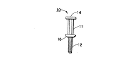
図1から図3には、複数の折丁を綴じて製本するために、または穿孔された複数のページを綴じて本にするために使用される可撓性綴じスタッド(Flexibind stud)を示すさまざまな図が示されている。可撓性綴じスタッドは、強力で硬度の低い(low durometer)伸縮可能な材料、例えばシリコーンゴムであり、底部及び上部キャップを有する。なお、可撓性があり、コストが安ければ、任意の可撓性部材を綴じ部材として使用できる。図1から図3において、ばらばらの本のページどうしを一時的にまとめるために使用可能なスタッド10が示されている。例えば、マニュアルや教材の改訂として、印刷したページを後にリングバインダに挿入し、短期間のプリント本、例えば、週間在庫目録などを生成する場合などである。可撓性綴じスタッド10は、シャフト部11及び12を含み、シャフト部11は上部キャップ14と底部キャップ16とのあいだに延び、シャフト部12は底部キャップ16の下方に延びている。可撓性綴じスタッド10は、強力で低デュロメータ40SAの材料、例えばシリコーンゴムで構成され、半円形ポストの形状を有する。ポストは、円形でもよいし、所望されれば他の任意の形状でもよい。
FIGS. 1 through 3 show various flexible binding studs used to bind and bind multiple signatures or to bind a plurality of perforated pages into a book. A simple diagram is shown. The flexible binding stud is a strong, low durometer stretchable material, such as silicone rubber, and has a bottom and top cap. Any flexible member can be used as the binding member as long as it is flexible and inexpensive. 1-3, a
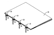
図4及び図5に示されるように、積み重ねた一組の穿孔ページ20を手でゆすって揃え、可撓性綴じスタッド10をページの上部孔から押し込み、キャップ14がページの上部に位置し、キャップ16がページの底部に位置するまで、底部孔を通して引っ張る。スタッド10の互いに向き合う端部にある可撓性綴じキャップ14及び16により、本を開いたときにページがばらばらになるのを防ぐ。スタッド10のシャフト部12は、ページの穿孔を通してスタッドを手で引っ張るために使用され、底部キャップ16の滑らかな外面を提供するために切り離してもよい。あるいは、可撓性シャフトはそのままにすることもでき、可撓性バインドを本から手で取り外した時、ペーパークリップが再使用できるのと同様に、これを、道具を用いずに再使用できる。図5に示されるように、キャップ14は半円の形状であり、そのため、折丁を開いたときにページが簡単に平らになる。
As shown in FIGS. 4 and 5, a set of stacked
図6において、また本発明の別の実施形態によれば、折丁40の綴じ端部に取り付けたステープル30が示されている。折丁は従来の方法で生成されている。すなわち、印刷され、積み重ねられ、ステープルで留められ、折り畳まれて、バインディングステーションに提示される。本発明に特有の特徴の1つが、王冠部35及び脚部材31、33を含むステープル30の使用であり、ステープルの王冠部35は、折丁の綴じ端部から約4mm突出している。図7に示されるように、3つ以上のステープルを各折丁に挿入できる。ステープル30の王冠部35の目的は、可撓性綴じスタッド10を挿入する「穴」を、折丁本体の外側に形成することである。「穴」の正確な形状は重要ではない。図6には1つの穴の形状が示されているが、穴は矩形、円形、長楕円形などの形状でもよい。
In FIG. 6 and according to another embodiment of the present invention, a
図8に示されるように、ステープル留めされた折丁は、対応するステープルがすべて上下に一直線上に並ぶように位置合わせされる。可撓性綴じスタッド10は、図示されるように、各ステープルと折丁の端部とのあいだの間隙に挿入される。こうして、すべての折丁が綴じ端部に沿ってまとめて保持される。可撓性バインドブックを開く際、任意の折丁の各ページは180度開くことができ、平らに置かれる。折丁の最終ページを開ける際も、綴じ部材が非常に可撓性であるため、ページは平らに置かれる。ただし、従来のスパイラルまたはデュアルワイヤバインドに見られるように、折丁どうしには小さい間隙がある。可撓性綴じ部材の可撓性の性質及び部材がシート自体を通過しないという事実によって、平らな綴じが実現する。可撓性綴じ部材はほぼ2倍に伸張可能なので、0.5インチ(1.27センチメートル)から2インチ(5.08センチメートル)の厚さの本に対して2種類のポストサイズのみが必要である。可撓性綴じ部材を供給するための、及びステープル留めされた折丁に可撓性綴じ部材を自動挿入するための任意の数の装置が想定可能であり、ここでは説明しない。
As shown in FIG. 8, the stapled signatures are aligned so that the corresponding staples are all aligned up and down. A flexible
平らに開ける小冊子に適応するために、穿孔ページの孔と折丁の綴じ端部に固定されたステープルに形成された穴のいずれかに挿入される、単純で低コストの可撓性綴じ部材が開示される。可撓性綴じ部材による製本は、穿孔及び標準的なにかわ綴じストリップに対して以下のような利点がある。(1)小冊子は「サブウェイ」すなわち360度折り曲げが可能である。(2)小冊子は、開いたときに平らになる。(3)穿孔からの紙くずが出ない。(4)可撓性綴じ部材による製本方法には、標準的なステープルを利用する。 To accommodate flat booklets, a simple, low-cost flexible binding member that is inserted into either a hole in the perforated page or a hole formed in a staple fixed to the binding end of a signature is provided. Disclosed. Binding with flexible binding members has the following advantages over perforations and standard glue binding strips: (1) The booklet can be “subway” or folded 360 degrees. (2) The booklet becomes flat when opened. (3) No paper waste from the perforations. (4) A standard staple is used for the bookbinding method using the flexible binding member.
10 可撓性スタッド、11,12 シャフト部、14 上部キャップ、16 底部キャップ、30 ステープル、35 王冠部、40 折丁。 10 flexible studs, 11, 12 shafts, 14 top caps, 16 bottom caps, 30 staples, 35 crowns, 40 signatures.
Claims (3)
少なくとも1つの可撓性部材と、At least one flexible member;
少なくとも1つのステープルと、At least one staple;
を含み、Including
前記少なくとも1つの可撓性部材は、上部キャップと、底部キャップと、これら2つのキャップの間にあり前記折丁の綴じ側の端部に沿って取り付けられる平坦な側面を備えたシャフト部と、を有し、前記上部キャップは、上部が平坦であり且つ半円形状であり、これにより、前記本を開いたときに前記折丁を平らな状態に開き易くし、The at least one flexible member includes a top cap, a bottom cap, and a shaft portion having a flat side surface between the two caps and attached along the binding side end of the signature; The upper cap has a flat top and is semicircular, thereby making it easier to open the signature in a flat state when the book is opened;
前記少なくとも1つのステープルは、前記折丁の綴じ側の端部に取り付けられることにより、その王冠部が穴を形成し、この穴に前記可撓性部材が挿入され、これにより、さらに前記折丁を平らな状態に開き易くする、The at least one staple is attached to the end of the signature on the binding side, so that the crown portion forms a hole, and the flexible member is inserted into the hole. Makes it easier to open in a flat state,
ことを特徴とする製本システム。A bookbinding system characterized by that.
2つのキャップ部を有する少なくとも1つの可撓性ポスト形状部材を含み、Including at least one flexible post-shaped member having two cap portions;
前記2つのキャップ部は、ページを綴じるために、あらかじめ穿孔されたページの孔の直径を超えて広がるように構成されて、前記あらかじめ穿孔されたページの最上ページと最下ページに載せられており、The two cap portions are configured to expand beyond the diameter of a hole of a pre-perforated page in order to bind the pages, and are placed on the uppermost page and the lowermost page of the pre-perforated page. ,
前記少なくとも1つの可撓性ポスト形状部材は、前記2つのキャップ部である上部キャップと底部キャップと、これら2つのキャップの間にあり前記あらかじめ穿孔されたページの孔に挿入される平坦な側面を備えたシャフト部と、を備え、The at least one flexible post-shaped member has an upper cap and a bottom cap that are the two cap portions, and a flat side surface that is interposed between the two caps and is inserted into the hole of the pre-drilled page. A shaft portion provided with,
前記上部キャップは、上部が平坦であり且つ半円形状であり、これにより、前記本を開いたときに前記あらかじめ穿孔されたページを平らな状態に開き易くする、The top cap has a flat top and a semicircular shape, which facilitates opening the pre-perforated page in a flat state when the book is opened.
ことを特徴とする器具。A device characterized by that.
シャフト部と、そのシャフト部の別々の位置から略直角に延伸する複数の平坦な表面とを含み、前記複数の平坦な表面の間に折丁が固定される、少なくとも一つの可撓性シングルピース部材を用い、
少なくとも一つのステープルであって、折丁の綴じ端部に取り付けられることにより、その王冠部が穴を形成し、この穴に前記可撓性シングルピース部材が挿入されて折丁を平らな状態に開くことができる、ステープルを用い、
前記少なくとも一つの可撓性シングルピース部材を、前記少なくとも一つのステープルの前記王冠部に挿入することで折丁を綴じる、
工程を含み、
前記可撓性シングルピース部材を、シリコーンゴムで形成し、前記複数の平坦な表面のうちの最底部の表面よりも下方に前記シャフト部が延びている、
ことを特徴とする方法。 A method of binding the end of a book signature,
At least one flexible single piece including a shaft portion and a plurality of flat surfaces extending substantially perpendicularly from different positions of the shaft portion, the signature being fixed between the plurality of flat surfaces Using the members,
At least one staple, which is attached to the binding end of the signature, so that the crown forms a hole, and the flexible single piece member is inserted into the hole to flatten the signature. Can be opened, using staples,
Binding the signature by inserting the at least one flexible single piece member into the crown of the at least one staple;
Including steps,
The flexible single piece member is formed of silicone rubber, and the shaft portion extends below the bottommost surface of the plurality of flat surfaces.
A method characterized by that.
Applications Claiming Priority (1)
| Application Number | Priority Date | Filing Date | Title |
|---|---|---|---|
| US10/338,961 US6955493B2 (en) | 2003-01-08 | 2003-01-08 | Flexibind books |
Publications (3)
| Publication Number | Publication Date |
|---|---|
| JP2004209987A JP2004209987A (en) | 2004-07-29 |
| JP2004209987A5 JP2004209987A5 (en) | 2007-02-08 |
| JP4659364B2 true JP4659364B2 (en) | 2011-03-30 |
Family
ID=32681524
Family Applications (1)
| Application Number | Title | Priority Date | Filing Date |
|---|---|---|---|
| JP2004001558A Expired - Fee Related JP4659364B2 (en) | 2003-01-08 | 2004-01-07 | Bookbinding system |
Country Status (2)
| Country | Link |
|---|---|
| US (1) | US6955493B2 (en) |
| JP (1) | JP4659364B2 (en) |
Families Citing this family (11)
| Publication number | Priority date | Publication date | Assignee | Title |
|---|---|---|---|---|
| WO2003020533A1 (en) * | 2001-08-29 | 2003-03-13 | General Binding Corporation | Binding elements for binding a wide range of thicknesses of stacks of sheets |
| US20040067094A1 (en) * | 2002-10-02 | 2004-04-08 | Hong Kong Stationery Manufacturing Co., Ltd. | Trigger construction for ring binder mechanism |
| US6955493B2 (en) * | 2003-01-08 | 2005-10-18 | Xerox Corporation | Flexibind books |
| EP1768857A4 (en) | 2004-07-12 | 2012-01-11 | Gen Binding Corp | Binding element and plurality of binding elements particularly suited for automated processes |
| ITVI20050219A1 (en) | 2005-08-02 | 2007-02-03 | Quintilia Pistolesi | DEVICE FOR THE REMOVABLE CONNECTION OF GROUPS OF SHEETS OR LAMINAR ELEMENTS, PARTICULARLY FOR COLLECTORS WITH RINGS OR SIMILAR SUPPORTS |
| US8123448B2 (en) | 2005-08-16 | 2012-02-28 | General Binding Corporation | Apparatus and methods for automatically binding a stack of sheets with a nonspiral binding element |
| US20070134628A1 (en) * | 2005-12-08 | 2007-06-14 | Capello Lawrence D | Bilingual safety manual |
| USD620977S1 (en) | 2006-08-04 | 2010-08-03 | General Binding Corporation | Binding element |
| US20080067798A1 (en) * | 2006-09-19 | 2008-03-20 | Daryl Lee Tempesta | Bookbinding and art framing zip tie system |
| ITUB20153493A1 (en) * | 2015-09-09 | 2017-03-09 | Gruppo Mecc Luciani S R L | EQUIPMENT FOR STUDIES APPLICATION. |
| USD852883S1 (en) * | 2017-09-22 | 2019-07-02 | Minbok Ltee | Binding element |
Citations (2)
| Publication number | Priority date | Publication date | Assignee | Title |
|---|---|---|---|---|
| JPS52120618U (en) * | 1976-03-10 | 1977-09-13 | ||
| JPH0495108U (en) * | 1990-12-26 | 1992-08-18 |
Family Cites Families (20)
| Publication number | Priority date | Publication date | Assignee | Title |
|---|---|---|---|---|
| US396088A (en) * | 1889-01-15 | Record or other file | ||
| US474509A (en) * | 1892-05-10 | John a | ||
| US549080A (en) * | 1895-10-29 | Temporary binder | ||
| US451710A (en) * | 1891-05-05 | Carl grtjlsrzweig | ||
| US708102A (en) * | 1902-06-16 | 1902-09-02 | John A Waldo Jr | Device for fastening loose-leaf books. |
| US877478A (en) * | 1907-01-09 | 1908-01-28 | William N Barnard | Temporary binder. |
| GB191204599A (en) * | 1912-02-23 | 1912-12-05 | Charles Edward Douglas | Improvements in and relating to the Temporary Binding of Pamphlets, Loose Sheets and the like. |
| US1142021A (en) * | 1914-08-31 | 1915-06-08 | Thomas Chambers | Loose-leaf binder. |
| US1526533A (en) * | 1923-12-06 | 1925-02-17 | Waldo Arthur Maas | Device for rapidly binding folded sheets, parts, and the like |
| US1630487A (en) * | 1925-10-08 | 1927-05-31 | Frank A Harrison | Sample book |
| US3467479A (en) * | 1967-08-28 | 1969-09-16 | Holes Webway Co | Loose-leaf binder |
| US3485564A (en) * | 1967-10-16 | 1969-12-23 | Holes Webway Co | Concealed binding and hinge means and cover |
| US4369013A (en) * | 1969-02-13 | 1983-01-18 | Velo-Bind, Inc. | Bookbinding strips |
| US3608115A (en) * | 1970-05-18 | 1971-09-28 | Holes Webway Co | Apparatus for making albums |
| US4674906A (en) * | 1984-10-22 | 1987-06-23 | Velo Bind, Inc. | Bookbinding strips and method of binding books |
| AT393106B (en) * | 1985-04-05 | 1991-08-26 | Jakob Lothar | STAPLING DEVICE FOR SHEET STACK |
| US4714366A (en) * | 1986-05-15 | 1987-12-22 | Boudrot John E | Loose-leaf document binder |
| US5620206A (en) * | 1995-05-19 | 1997-04-15 | Flores; Adalberto | Apparatus for binding materials |
| US6409447B2 (en) * | 2000-02-03 | 2002-06-25 | Tanarax, Llc | Bookbinding signature comb and spine device |
| US6955493B2 (en) * | 2003-01-08 | 2005-10-18 | Xerox Corporation | Flexibind books |
-
2003
- 2003-01-08 US US10/338,961 patent/US6955493B2/en not_active Expired - Lifetime
-
2004
- 2004-01-07 JP JP2004001558A patent/JP4659364B2/en not_active Expired - Fee Related
Patent Citations (2)
| Publication number | Priority date | Publication date | Assignee | Title |
|---|---|---|---|---|
| JPS52120618U (en) * | 1976-03-10 | 1977-09-13 | ||
| JPH0495108U (en) * | 1990-12-26 | 1992-08-18 |
Also Published As
| Publication number | Publication date |
|---|---|
| JP2004209987A (en) | 2004-07-29 |
| US20040131446A1 (en) | 2004-07-08 |
| US6955493B2 (en) | 2005-10-18 |
Similar Documents
| Publication | Publication Date | Title |
|---|---|---|
| US5683111A (en) | Binder system and kit | |
| JP4659364B2 (en) | Bookbinding system | |
| EP1934058B1 (en) | Method for binding a bundle of loose leaves or the like and binding element, end leaf or cover applied thereby | |
| US6210065B1 (en) | Sequential first page notebook | |
| US6409447B2 (en) | Bookbinding signature comb and spine device | |
| US3956798A (en) | Flexible binding | |
| US717957A (en) | Loose leaf for temporary binders. | |
| US4072326A (en) | Wrap-around cover for books | |
| US20050047894A1 (en) | Method for binding graphic products | |
| RU2698145C1 (en) | Method of stitching a pack of sheets and a book or magazine obtained using said method | |
| US20100129179A1 (en) | Self-binding system | |
| AU2018281028B2 (en) | Method for binding a bundle of leaves | |
| US8925968B2 (en) | Composition book | |
| US2250018A (en) | Binding | |
| JP2695620B2 (en) | File | |
| US1737052A (en) | Scrapbook and leaf unit therefor | |
| US4560299A (en) | Presentation folder | |
| WO2021148867A1 (en) | Kit and method for binding a bundle of leaves | |
| US1358421A (en) | Bookbinding | |
| US736339A (en) | Binding-file attachment. | |
| JPS6126064Y2 (en) | ||
| US3435828A (en) | Article and method for retaining loose leaves in bound volumes | |
| JP2003039852A (en) | Cover for coil binding and coil-bound booklet with the cover | |
| US1169868A (en) | Bookbinding. | |
| US1735211A (en) | Bookbinder |
Legal Events
| Date | Code | Title | Description |
|---|---|---|---|
| A521 | Request for written amendment filed |
Free format text: JAPANESE INTERMEDIATE CODE: A523 Effective date: 20061213 |
|
| A621 | Written request for application examination |
Free format text: JAPANESE INTERMEDIATE CODE: A621 Effective date: 20061213 |
|
| A131 | Notification of reasons for refusal |
Free format text: JAPANESE INTERMEDIATE CODE: A131 Effective date: 20100316 |
|
| A521 | Request for written amendment filed |
Free format text: JAPANESE INTERMEDIATE CODE: A523 Effective date: 20100601 |
|
| TRDD | Decision of grant or rejection written | ||
| A01 | Written decision to grant a patent or to grant a registration (utility model) |
Free format text: JAPANESE INTERMEDIATE CODE: A01 Effective date: 20101207 |
|
| A01 | Written decision to grant a patent or to grant a registration (utility model) |
Free format text: JAPANESE INTERMEDIATE CODE: A01 |
|
| A61 | First payment of annual fees (during grant procedure) |
Free format text: JAPANESE INTERMEDIATE CODE: A61 Effective date: 20101227 |
|
| FPAY | Renewal fee payment (event date is renewal date of database) |
Free format text: PAYMENT UNTIL: 20140107 Year of fee payment: 3 |
|
| R150 | Certificate of patent or registration of utility model |
Free format text: JAPANESE INTERMEDIATE CODE: R150 |
|
| R250 | Receipt of annual fees |
Free format text: JAPANESE INTERMEDIATE CODE: R250 |
|
| R250 | Receipt of annual fees |
Free format text: JAPANESE INTERMEDIATE CODE: R250 |
|
| R250 | Receipt of annual fees |
Free format text: JAPANESE INTERMEDIATE CODE: R250 |
|
| R250 | Receipt of annual fees |
Free format text: JAPANESE INTERMEDIATE CODE: R250 |
|
| LAPS | Cancellation because of no payment of annual fees |