JP4657082B2 - Ultrasonic therapy device - Google Patents
Ultrasonic therapy device Download PDFInfo
- Publication number
- JP4657082B2 JP4657082B2 JP2005314323A JP2005314323A JP4657082B2 JP 4657082 B2 JP4657082 B2 JP 4657082B2 JP 2005314323 A JP2005314323 A JP 2005314323A JP 2005314323 A JP2005314323 A JP 2005314323A JP 4657082 B2 JP4657082 B2 JP 4657082B2
- Authority
- JP
- Japan
- Prior art keywords
- actuator
- electrostrictive polymer
- electrode
- blade
- treatment
- Prior art date
- Legal status (The legal status is an assumption and is not a legal conclusion. Google has not performed a legal analysis and makes no representation as to the accuracy of the status listed.)
- Expired - Fee Related
Links
Images


Classifications
-
- A—HUMAN NECESSITIES
- A61—MEDICAL OR VETERINARY SCIENCE; HYGIENE
- A61B—DIAGNOSIS; SURGERY; IDENTIFICATION
- A61B17/00—Surgical instruments, devices or methods, e.g. tourniquets
- A61B17/32—Surgical cutting instruments
- A61B17/320068—Surgical cutting instruments using mechanical vibrations, e.g. ultrasonic
- A61B2017/32007—Surgical cutting instruments using mechanical vibrations, e.g. ultrasonic with suction or vacuum means
-
- A—HUMAN NECESSITIES
- A61—MEDICAL OR VETERINARY SCIENCE; HYGIENE
- A61B—DIAGNOSIS; SURGERY; IDENTIFICATION
- A61B17/00—Surgical instruments, devices or methods, e.g. tourniquets
- A61B17/32—Surgical cutting instruments
- A61B17/320068—Surgical cutting instruments using mechanical vibrations, e.g. ultrasonic
- A61B2017/320071—Surgical cutting instruments using mechanical vibrations, e.g. ultrasonic with articulating means for working tip
-
- A—HUMAN NECESSITIES
- A61—MEDICAL OR VETERINARY SCIENCE; HYGIENE
- A61B—DIAGNOSIS; SURGERY; IDENTIFICATION
- A61B17/00—Surgical instruments, devices or methods, e.g. tourniquets
- A61B17/32—Surgical cutting instruments
- A61B17/320068—Surgical cutting instruments using mechanical vibrations, e.g. ultrasonic
- A61B2017/320082—Surgical cutting instruments using mechanical vibrations, e.g. ultrasonic for incising tissue
Description
この発明は、例えば外科手術等の手術において生体組織を凝固・切開するのに用いられる超音波治療装置に関する。 The present invention relates to an ultrasonic treatment apparatus used for coagulation / incision of a living tissue in an operation such as a surgical operation.
一般に、開腹して外科手術を施す場合や、内視鏡下外科手術を施す場合には、生体組織の凝固・切開を行う手段として超音波治療装置が用いられる。このような超音波治療装置は、超音波振動子で発振された超音波振動が増幅されて処置部を構成する超音波プローブに伝達され、その超音波振動を利用して生体組織の凝固・切開処置が行われる。 In general, when performing a surgical operation with an abdomen or performing an endoscopic surgical operation, an ultrasonic therapy apparatus is used as a means for coagulating and incising a living tissue. In such an ultrasonic therapy apparatus, ultrasonic vibrations oscillated by an ultrasonic transducer are amplified and transmitted to an ultrasonic probe constituting a treatment section, and the ultrasonic vibration is used to coagulate and incise living tissue. Treatment is performed.
そして、この超音波治療装置に用いられている超音波振動子としては、圧電素子及び電極を交互に積層して、ホーンと裏打ち板との間に締結配置したボルト締めランジュバン型振動子構造(例えば、特許文献1参照)、磁歪材料をコイルで巻いた磁歪型振動子構造(例えば、特許文献2参照)のものが知られている。 As an ultrasonic transducer used in this ultrasonic therapy apparatus, a bolt-clamped Langevin type transducer structure (for example, a piezoelectric element and an electrode are alternately stacked and fastened between a horn and a backing plate (for example, And a magnetostrictive vibrator structure in which a magnetostrictive material is wound with a coil (see, for example, Patent Document 2) is known.
しかしながら、上記超音波治療装置では、超音波振動子の歪率が1%程度のために、超音波振動子の振幅を大きくして処置能力を高めると、超音波振動子が大型となるという問題を有する。このため、上記超音波治療装置にあっては、内視鏡を用いる治療において要請されている、例えば内視鏡の挿入部に設けられるチャンネルに挿入して所望の処置に供するまでの小型が困難である。 However, in the above ultrasonic therapy apparatus, since the distortion rate of the ultrasonic transducer is about 1%, the ultrasonic transducer becomes large when the amplitude of the ultrasonic transducer is increased to increase the treatment capability. Have For this reason, it is difficult to miniaturize the ultrasonic treatment apparatus until it is inserted into a channel provided in an insertion portion of an endoscope and used for a desired treatment, which is required in the treatment using an endoscope. It is.
ところで、最近、人工筋肉の素材候補として、誘電エストラマーと称する電場応答性の高分子材料であるシリコーン樹脂やアクリル系樹脂等の電歪高分子を用いることが考えられている(例えば、非特許文献1、2及び3参照。)。このような電歪高分子を用いたアクチュエータは、その電歪高分子の両面に電極を薄膜形成して、電極間に電圧を印加すると、一方面が収縮して他方面が伸展することで、その電極間に周期的に電圧を印加することにより、電歪高分子が伸縮して所望の駆動力を発生する。 Recently, it has been considered to use electrostrictive polymers such as silicone resins and acrylic resins, which are electric field responsive polymer materials called dielectric elastomers, as candidate materials for artificial muscles (for example, non-patent literature). See 1, 2 and 3.) An actuator using such an electrostrictive polymer has electrodes formed on both sides of the electrostrictive polymer, and when a voltage is applied between the electrodes, one surface contracts and the other surface extends, By applying a voltage periodically between the electrodes, the electrostrictive polymer expands and contracts to generate a desired driving force.
そして、このような電歪高分子を利用したアクチュエータとしては、義手、義足パブティックやセンシングが可能な皮膚、血液等を診断するポンプ等の人工機器や治療機器等への応用が研究されている(例えば、非特許文献3参照。)。
And as an actuator using such an electrostrictive polymer, application to artificial devices such as artificial hands such as artificial pumps, blood pumps for diagnosis of artificial hands, artificial legs, boutiques and blood, etc., and therapeutic devices has been studied. (For example, refer
例えば電歪高分子を利用したアクチュエータを治療機器等に応用する場合には、単に、治療に適するまでの小型化を実現すればよいものでなく、小型化の要請を満足したうえで、その他の構成部品と有機的に結合して信頼性の高い安定した動作制御を実現することが要請される。
この発明は、上記の事情に鑑みてなされたもので、簡易な構成で、且つ、小型化の促進を図り得るようにした超音波治療装置を提供することを目的とする。 The present invention has been made in view of the above circumstances, and an object of the present invention is to provide an ultrasonic treatment apparatus having a simple configuration and capable of promoting miniaturization.
本発明の一実施態様では、超音波治療装置は、伸縮駆動するアクチュエータと、前記アクチュエータに接続され、前記アクチュエータの伸縮駆動に連動して超音波振動して、治療部位を処置する処置部と、を具備し、前記アクチュエータは、互いに対向する第1及び第2の対向面を備える外面を有する電歪高分子部材と、前記電歪高分子部材の外面の前記第1の対向面に設けられている第1の電極部材と、前記電歪高分子部材の外面の前記第2の対向面に設けられ、前記第1の電極部材に対して分離されている第2の電極部材と、前記電歪高分子部材に埋設され、前記第1の電極部材に接続されている複数の第1の内部電極部材と、前記電歪高分子部材に埋設され、前記第2の電極部材に接続され、前記複数の第1の内部電極部材に対して前記第1及び前記第2の対向面の面方向と略直交する方向に交互に離間されて対設されている複数の第2の内部電極部材と、を有し、前記第1の電極部材と前記第2の電極部材との間に交流電圧が印加される場合には、前記電歪高分子部材が伸縮駆動される、ことを特徴とする。
In one embodiment of the present invention, an ultrasonic therapy apparatus includes an actuator that drives to extend and contract, and a treatment unit that is connected to the actuator and ultrasonically vibrates in conjunction with the extension and contraction of the actuator to treat a treatment site. comprising a said actuator, electrostrictive polymer member having an outer surface comprising first and second opposing surfaces facing each other, provided on said first opposing surface of the outer surface of the electrostrictive polymer member A first electrode member, a second electrode member provided on the second facing surface of the outer surface of the electrostrictive polymer member, and separated from the first electrode member, and the electrostriction is embedded in the polymer member, a plurality of first inner electrode member connected to the first electrode member, wherein embedded in the electrostrictive polymer member, is connected to the second electrode member, said plurality before the first inner electrode member Includes a plurality of second inner electrode member which are spaced alternately in the direction which is oppositely arranged substantially orthogonal to the surface direction of the first and second opposing faces, the, the and the first electrode member When an AC voltage is applied between the second electrode member and the second electrode member, the electrostrictive polymer member is driven to expand and contract.
以上のように、この発明によれば、簡易な構成で、且つ、小型化の促進を図り得るようにした超音波治療装置を提供することができる。 As described above, according to the present invention, it is possible to provide an ultrasonic therapy apparatus that has a simple configuration and can promote miniaturization.
以下、この発明の実施の形態について、図面を参照して詳細に説明する。 Hereinafter, embodiments of the present invention will be described in detail with reference to the drawings.
(第1の実施の形態)
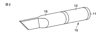
図1は、この発明の第1の実施の形態に係る超音波治療装置の要部を示すもので、超音波振動子を構成するアクチュエータ10は、チューブ状の電歪高分子11の外周面及び内周面に伸縮自在なプラス12電極及びマイナス電極13が分離して配される(図2及び図3参照)。
(First embodiment)
FIG. 1 shows an essential part of an ultrasonic therapy apparatus according to a first embodiment of the present invention. An
この電歪高分子11は、弾性を有するいわゆるコンデンサーであり、上述した非特許文献2に示されるように誘電エラストマと称され、例えばアクリル、シリコン、ポリウレタン等の樹脂材料でチューブ状に形成される。そして、プラス電極12及びマイナス電極13は、例えばフォトリソグラフィーを用いて成膜した電極、あるいはバインダとカーボン微粒子を混ぜて吹き付けたカーボン電極等が用いられる。
The
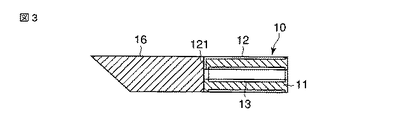
上記アクチュエータ10のプラス電極12は、プラス電極接続端121が電歪高分子11の内径まで延出される。そして、このプラス電極接続端121及びマイナス電極13には、配線ケーブル14,14の一端が接続される。
The plus
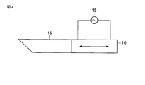
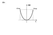
この配線ケーブル14の他端には、電源手段を構成する電源15に接続され(図4参照)、この電源15から電圧を上記プラス電極12及びマイナス電極13に所望の周期で印加する。これにより、電歪高分子11は、上述した非特許文献3に示されるように電圧の周期に同期してプラス電極12とマイナス電極13との間に引力が発生して面方向(外周面から内周面方向)に収縮され、その面方向と直交する方向(チューブ軸方向)に伸展される(図5(a)(b)参照)。この歪率は、図6に示すように印加する電界Eの二乗に比例され、数10%〜300%以上となることが確認される。
The other end of the
上記アクチュエータ10には、その一端部に処置部を構成するブレード16が例えば接着、スポット溶接、ロー付け等の接合方法により接合される。そして、このアクチュエータ10の他端部には、可撓性部材であるシース17を介して処置操作部18が設けられ、この処置操作部18には、ケーブル引き出し口181が設けられる。このケーブル引き出し口181には、上記アクチュエータ10のプラス電極12及びマイナス電極13に接続された配線ケーブル14,14が上記シース17に設けられた挿通孔171に挿通された後、挿通されて外部に引き出される。そして、このケーブル引き出し口181から引き出された配線ケーブル14は、上記電源15に接続される。
A
また、上記アクチュエータ10及びシース17には、例えば図7に示すようにテフロン(登録商標)、ポリエチレン、アクリル、シリコン、ポリウレタン等の樹脂材料で形成した保護用樹脂チューブ19が例えば接着剤を用いて被覆される。この樹脂チューブ19としては、その他、少なくとも図8に示すようにアクチュエータ10を覆うように設けるだけでも良い。これにより、アクチュエータ保護の促進が図れる。
Further, for example, as shown in FIG. 7, a
上記ブレード16、アクチュエータ10及びシース17は、図9に示すように内視鏡1の挿入部2の手元側に配される口金3を通して該挿入部2に設けられたチャンネル4に挿入されて装着される(図10参照)。ここで、ブレード16は、挿入部2の撮像レンズ系5に並設されて操作自在に配置される。この状態で、アクチュエータ10は、その電歪高分子11のプラス電極12及びマイナス電極13に対して上記電源15からの電圧が所望の周期で印加されると、電歪高分子11がチューブ軸方向に伸縮駆動されてブレード16を超音波振動させ、ここに、ブレード16を用いた生体組織の切開・止血等の処置が可能となる。
The
上記構成において、生体組織の切開・止血等の処置を行う場合には、先ず内視鏡1の挿入部2を体腔内に挿入し、その撮像レンズ系5を通して体腔内を撮像してその画像を観察し、患部を確認する。この内視鏡1を介して患部を確認した状態で、ブレード16、アクチュエータ10及びシース17を挿入部2の口金3からチャンネル4内に順に挿入して装着する。
In the above configuration, when performing a treatment such as incision or hemostasis of a living tissue, first, the
次に、患部の観察を行いながら処置操作部18を操作して、ブレード16を前後に移動させて処置部位に合わせ、上記超音波発生操作手段(図示せず)を操作する。ここで、アクチュエータ10のプラス電極12及びマイナス電極13には、電源15から電圧が所望の周期で印加される。すると、アクチュエータ10は、その電歪高分子11が電源15からの電圧の供給周期に同期してチューブ軸方向に伸縮され、ここに、ブレード16が超音波振動されて生体組織の切開・止血処置が行われる。
Next, the
このように、上記超音波治療装置は、電歪高分子11にプラス電極12及びマイナス電極13を配し、その電極12,13間に電圧が印加されると、電歪高分子11が伸縮駆動されるアクチュエータ10を備えて、アクチュエータ10のプラス電極12及びマイナス電極13に電圧を所定の周期で供給して電歪高分子11を伸縮駆動させ、ブレード16を超音波振動させるように構成した。
As described above, in the ultrasonic therapy apparatus, the
これによれば、アクチュエータ10は、そのプラス電極12とマイナス電極13間に電圧が印加されると、上述した非特許文献1及び3に示されるように電歪高分子11の電極12,13に対応する一方方向が収縮されて、その直交する他方方向が数10%〜数100%の歪率で伸展され、印加される電圧の周期に同期して伸縮されてブレード16を超音波振動する。これにより、ブレード16を大きな振幅で超音波振動することが可能となり、高い処置能力を有するブレード16を、小型のアクチュエータ10を用いて実現することが可能となり、装置の小型化を図ることができる。
According to this, when a voltage is applied between the plus
また、上記説明では、アクチュエータ10の電歪高分子11をブレード16に接着、スポット溶接、ロー付け等の手法で接合するように構成した場合で説明したが、これに限ることなく、その他、例えば図11に示すように押さえ部材20及び線材21を用いて電歪高分子11とブレード16を固定配置するように構成しても良く、同様の効果が期待される。
In the above description, the
即ち、線材21は、上記ブレード16に突出して設けられ、その先端部に螺子部211が形成される。この線材21は、例えば導電性を有する金属等で形成した場合、絶縁チューブ22が被覆されて上記電歪高分子11内に挿通される。そして、この線材21の螺子部211には、上記押さえ部材20に設けられた螺子孔201が螺合される。これにより、アクチュエータ10の電歪高分子11は、ブレード16に線材21及び押さえ部材20を介して固定配置される。
That is, the
また、アクチュエータ10を線材21及び押さえ部材20を用いてブレード16に接合固定する場合には、例えば図12乃至図14に示すように少なくとも2枚の膜状の電歪高分子11aを用いて形成することで、さらに歪率の向上を図ることが可能となる。
When the
即ち、両面にプラス電極12及びマイナス電極13を形成した膜状の電歪高分子11aを2枚、例えば互いのマイナス電極13を重ねて線材21に巻き付けて形成する。上述した非特許文献1に示されるように線材21ではなく、ばねを用いても良いが、線材21を用いる方がより剛性を高くでき、周波数特性をより向上させることができる。この際、電歪高分子11aを予め、伸展させた状態で形成することが可能となり、そのプラス電極12及びマイナス電極13に対して電圧を印加した際の歪を大きく設定することが可能となる。
That is, two film-like
この電歪高分子構成の場合、上記押さえ部材20には、図14に示すように線材挿通孔202、一対の電極挿通孔203が設けられる。このうち線材挿通孔202には、上記ブレード16に固定された線材21が挿通され、この線材21の先端部に固定部材23が取り付けられて押さえ部材20に固定される。他方の電極挿通孔203には、上記プラス電極及びマイナス電極12,13に接続されたプラス電極接続端121a及びマイナス電極接続端131(図12参照)が挿通され、上記配線ケーブル14を介して電源15に接続される。
In the case of this electrostrictive polymer configuration, the pressing
さらに、上記説明では、アクチュエータ10の電歪高分子11としてチューブ状のものを用いて構成した場合で説明したが、これに限るものでなく、その他、例えば図15乃至図18に示すように構成しても良く、同様の効果が期待される。但し、この図15乃至図18においては、上記図1乃至図14と同一部分について同一符号を付して、その詳細な説明を省略する。
Furthermore, in the above description, the
図15及び図16では、電歪高分子111を矩形状に形成して、その対向する両側面にプラス電極12及びマイナス電極13を分離して配し、このプラス電極12及びマイナス電極13は、上記電源15に接続させる。そして、このプラス電極12及びマイナス電極には、それぞれ電歪高分子111内に面方向と略平行に埋設された、例えば複数のプラス内部電極12a及びマイナス内部電極13aが接続される(図16参照)。この複数のプラス内部電極12a及びマイナス内部電極13aは、例えば電歪高分子111の面方向に交互に所定の間隔を有して対設するように埋設される。
15 and 16, the
図17及び図18は、電歪高分子112を矩形状に形成して、その上下面にプラス電極12及びマイナス電極13を分離して配し、このプラス電極12及びマイナス電極13は、上記電源15に接続させる。そして、このプラス電極12及びマイナス電極13には、それぞれ電歪高分子112内に面方向と略直交して埋設された、例えば複数のプラス内部電極12b及びマイナス内部電極13bが接続される(図18参照)。この複数のプラス内部電極12b及びマイナス内部電極13bは、例えば電歪高分子112の面方向と直交する方向に交互に所定の間隔を有して対設するように埋設される。
17 and 18, the
(第2の実施の形態)
図19乃至図23は、この発明の第2の実施の形態に係る超音波治療装置を示すもので、上記第1の実施の形態と同様の効果が期待される。但し、この図19乃至図23においては、上記第1の実施の形態と同一部分について同一符号を付して、その詳細な説明を省略する。
(Second Embodiment)
19 to 23 show an ultrasonic therapy apparatus according to the second embodiment of the present invention, and the same effects as those of the first embodiment are expected. However, in FIG. 19 to FIG. 23, the same parts as those in the first embodiment are denoted by the same reference numerals, and detailed description thereof is omitted.
即ち、第2の実施の形態では、図19に示すように生体組織の粉砕・乳化処置を施すように処置部であるブレード16に挿通孔161を設けた処置具構造に適用するように構成した。このブレード16の挿通孔161には、チューブ24の一端が挿入される(図20参照)。このチューブ24の他端部は、上記アクチュエータ10の電歪高分子11a(上記図12参照)内に挿通された後、上記シース17内に挿通され、処置操作部18に設けられるチューブ排出口182から引き出されて排出ポンプ25に連結される。
That is, in the second embodiment, as shown in FIG. 19, it is configured to be applied to a treatment instrument structure in which an
この場合、アクチュエータ10は、例えば上記図12に示すように膜状の電歪高分子11aの両面にプラス電極12及びマイナス電極13を積層形成して、互いのマイナス電極13同士を重ねて上記チューブ24の周囲に巻き付けてられる(図21参照)。この際、プラス12電極及びマイナス電極13は、配線ケーブル14を介してシース17とチューブ24との間の隙間を通して処置操作部18まで配線接続され、この配線ケーブル14がケーブル引き出し口181から引き出されて上記電源15に接続される。
In this case, for example, as shown in FIG. 12, the
また、上記アクチュエータ10及びシース17は、例えば図22に示すように上記第1の実施の形態と同様のテフロン、ポリエチレン、アクリル、シリコン、ポリウレタン等の樹脂材料で形成した保護用樹脂チューブ19が被されて接着される。この樹脂チューブ19としては、その他、少なくとも図23に示すようにアクチュエータ10を覆うように設けるだけでも良い。これにより、アクチュエータ保護の促進が図れる。
Further, for example, as shown in FIG. 22, the
上記構成において、生体組織の粉砕・乳化処置を行う場合には、先ず上記内視鏡1の挿入部2を体腔内に挿入し、その撮像レンズ系5を通して体腔内を撮像してその画像を観察し、患部を確認する。この内視鏡1を介して患部を確認した状態で、ブレード16、アクチュエータ10及びシース17を挿入部2の口金3からチャンネル4内に順に挿入して装着する。
In the above configuration, when performing pulverization / emulsification treatment of the living tissue, first, the
次に、患部の観察を行いながら処置操作部18を操作して、ブレード16を前後に移動させて処置部位に合わせ、上記超音波発生操作手段(図示せず)を操作する。ここで、アクチュエータ10のプラス電極12及びマイナス電極13には、電源15から電圧が所望の周期で印加される。すると、アクチュエータ10は、その電歪高分子11aが電源15からの電圧の供給周期に同期してチューブ軸方向に伸縮され、ここに、ブレード16が超音波振動されて生体組織の粉砕・乳化処置が行われる。
Next, the
この際、排出ポンプ25が駆動され、粉砕・乳化処置した生体組織がブレード16の挿通孔161に吸引されてチューブ24を通して排出ポンプ25から図示しない排出瓶に排出される。
At this time, the
(第3の実施の形態)
図24乃至図28は、この発明の第3の実施の形態に係る超音波治療装置を示すもので、上記第1の実施の形態と同様の効果が期待される。但し、この図24乃至図28においては、上記第1の実施の形態と同一部分について同一符号を付して、その詳細な説明を省略する。
(Third embodiment)
FIGS. 24 to 28 show an ultrasonic therapy apparatus according to the third embodiment of the present invention, and the same effects as those of the first embodiment are expected. However, in FIGS. 24 to 28, the same parts as those in the first embodiment are denoted by the same reference numerals, and detailed description thereof is omitted.
即ち、第3の実施の形態では、図24に示すように生体組織を挟んで強固・切開処置を施すように処置部であるブレード26の基端部に鉗子片27を開閉自在に配した処置具構造に適用するように構成した。このブレード26は、図25及び図26に示すように有底筒状に形成され、その内部に上記アクチュエータ10が挿入される。
That is, in the third embodiment, as shown in FIG. 24, a treatment in which a
このアクチュエータ10は、上述したようにチューブ状の電歪高分子11の内周面及び外周面にプラス電極12及びマイナス電極13が設けられ、電歪高分子11の先端部がブレード26の底面に取付けられる(図26参照)。この電歪高分子11の他端部には、先端カバー部材28の一端部が取付けられ、この先端カバー部材28の他端部には、上記可撓性を有したシース17の先端部が取付けられる。
In the
なお、上記アクチュエータ10としては、上記第1の実施の形態において説明したいずれの構成のものを用いて適用可能で、同様の効果が期待される。
The
上記ブレード26に内挿されたアクチュエータ10には、例えば図27に示すように上記第1及び第2の実施の形態と同様のテフロン、ポリエチレン、アクリル、シリコン、ポリウレタン等の樹脂材料で形成した保護用樹脂チューブ19が被されて接着される。これにより、アクチュエータ保護の促進が図れる。
For example, as shown in FIG. 27, the
上記先端カバー部材28には、鉗子片27の中間部が主軸ピン281を介して回動自在に支持される(図25参照)。この先端カバー部材28の基端部には、リンク部材29の一端部が支持ピン291を介して回動自在に取付けられる。そして、リンク部材29の基端部には、連結部材30が操作ピン301を介して回動自在に取付けられる。
An intermediate portion of the
この連結部材30は、先端カバー部材28に設けられる案内溝282に軸方向に移動自在に配される。そして、この連結部材30には、操作ワイヤ31の先端部が取付けられる。この操作ワイヤ31は、上記シース17内に挿通されて上記処置操作部18に移動操作自在に設けられるハンドル32が取付けられ、このハンドル32の摺動操作により矢印A,B方向に移動付勢される。
The connecting
上記鉗子片27は、ハンドル32を操作して操作ワイヤ31が矢印A方向に引き込まれると、リンク部材29が連結部材30、操作ピン301を介して時計方向に回動されることにより、主軸ピン281を中心として反時計方向に回動され、ブレード26に対して図示しない生体組織を挟んで閉じられる。そして、鉗子片27は、上記ハンドル32が反転操作されると、上記操作ワイヤ31が矢印B方向に移動付勢され、挟持動作と逆に時計方向に回動されて上記ブレード26から離間される。
When the
また、上記先端カバー28には、上記アクチュエータ10のプラス電極12及びマイナス電極13に接続された配線ケーブル14が挿通され、この配線ケーブル14が上記電源15に接続される。これにより、アクチュエータ10は、電源15からの電圧が配線ケーブル14を介してプラス電極12及びマイナス電極13間に印加され、その印加される周期に応じて、図28(a)に示す初期位置から矢印B方向(軸方向)に伸展される(同図(b)参照)。
In addition, a
上記構成において、生体組織の凝固・切開処置を行う場合には、先ず上記内視鏡1の挿入部2を体腔内に挿入し、その撮像レンズ系5を通して体腔内を撮像してその画像を観察し、患部を確認する。この内視鏡1を介して患部を確認した状態で、ブレード26、アクチュエータ10及びシース17を挿入部2の口金3からチャンネル4内に順に挿入して装着する。
In the above configuration, when coagulation / incision treatment of a living tissue is performed, first, the
ここで、処置操作部18のハンドル32を操作して鉗子片27を開き、ブレード26と鉗子片27との間に患部が位置するように移動調整して、位置したのを確認した状態で、ハンドル32を反転操作して鉗子片27を閉方向に回動させて鉗子片27とブレード26との間で生体組織を挟持する。
Here, by operating the
次に、挟持状態を確認しながら処置操作部18を操作して、電源15の電圧を所望の周期でアクチュエータ10のプラス電極12及びマイナス電極13に印加する。すると、アクチュエータ10は、その電歪高分子11が電源15からの電圧の供給周期に同期してチューブ軸方向に伸縮され、ここに、ブレード26が超音波振動されて鉗子片27との間で挟持した生体組織の粉砕・乳化処置が行われる。
Next, the
なお、この発明は、上記実施の形態に限ることなく、その他、実施段階ではその要旨を逸脱しない範囲で種々の変形を実施し得ることが可能である。さらに、上記実施の形態には、種々の段階の発明が含まれており、開示される複数の構成要件における適宜な組合せにより種々の発明が抽出され得る。 The present invention is not limited to the above-described embodiment, and various modifications can be made without departing from the scope of the invention at the stage of implementation. Further, the above embodiments include inventions at various stages, and various inventions can be extracted by appropriately combining a plurality of disclosed constituent elements.
例えば実施の形態に示される全構成要件から幾つかの構成要件が削除されても、発明が解決しようとする課題の欄で述べた課題が解決でき、発明の効果で述べられている効果が得られる場合には、この構成要件が削除された構成が発明として抽出され得る。 For example, even if some constituent requirements are deleted from all the constituent requirements shown in the embodiment, the problem described in the column of the problem to be solved by the invention can be solved, and the effect described in the effect of the invention can be obtained. In such a case, a configuration in which this configuration requirement is deleted can be extracted as an invention.
また、この発明は、上記各実施の形態によれば、その他、次のような構成を得ることもできる。 In addition, according to each of the above embodiments, the present invention can also obtain the following configuration.
(付記1)
超音波振動により治療部位を処置する超音波治療装置において、
電歪高分子と2つ以上の電極を有し、前記電極間に電圧が印加されると、前記電歪高分子が伸縮駆動される電歪高分子アクチュエータと、
前記電歪高分子アクチュエータに接合され、前記電歪高分子アクチュエータの伸縮駆動に連動して超音波振動し、前記治療部位を処置するブレードと、
電歪高分子アクチュエータの電極間に交流電圧を供給する電源と、
を具備することを特徴とする超音波治療装置。
(Appendix 1)
In an ultrasonic therapy apparatus for treating a treatment site by ultrasonic vibration,
An electrostrictive polymer actuator having two or more electrodes, and when a voltage is applied between the electrodes, the electrostrictive polymer actuator is driven to expand and contract;
A blade that is bonded to the electrostrictive polymer actuator, ultrasonically vibrates in conjunction with the expansion and contraction drive of the electrostrictive polymer actuator, and treats the treatment site;
A power source for supplying an AC voltage between the electrodes of the electrostrictive polymer actuator;
An ultrasonic therapy apparatus comprising:
(付記2)
内視鏡観察下で超音波振動により治療部位を処置する超音波治療装置において、
電歪高分子と2つ以上の電極を有し、前記電極間に電圧が印加されると、前記電歪高分子が伸縮駆動される電歪高分子アクチュエータと、
前記電歪高分子アクチュエータに接合され、前記電歪高分子アクチュエータの伸縮駆動に連動して超音波振動し、前記治療部位を処置するブレードと、
電歪高分子アクチュエータの電極間に交流電圧を供給する電源と、
前記電歪高分子アクチュエータを支持する可撓性を有したシースと、
前記シースの基端部に配され、前記電源を制御して電歪高分子アクチュエータを動作制御する操作部と、
を具備することを特徴とする超音波治療装置。
(Appendix 2)
In an ultrasonic therapy apparatus that treats a treatment site by ultrasonic vibration under endoscopic observation,
An electrostrictive polymer actuator having two or more electrodes, and when a voltage is applied between the electrodes, the electrostrictive polymer actuator is driven to expand and contract;
A blade that is bonded to the electrostrictive polymer actuator, ultrasonically vibrates in conjunction with the expansion and contraction drive of the electrostrictive polymer actuator, and treats the treatment site;
A power source for supplying an AC voltage between the electrodes of the electrostrictive polymer actuator;
A flexible sheath for supporting the electrostrictive polymer actuator;
An operation unit that is arranged at a proximal end portion of the sheath and controls the operation of the electrostrictive polymer actuator by controlling the power source,
An ultrasonic therapy apparatus comprising:
(付記3)
内視鏡観察下で超音波振動により治療部位を処置する超音波治療装置において、
電歪高分子と2つ以上の電極を有し、前記電極間に電圧が印加されると、前記電歪高分子が伸縮駆動される電歪高分子アクチュエータと、
前記電歪高分子アクチュエータに接合され、前記電歪高分子アクチュエータの伸縮駆動に連動して超音波振動し、前記治療部位を処置する中空状のブレードと、
電歪高分子アクチュエータの電極間に交流電圧を供給する電源と、
前記電歪高分子アクチュエータを支持する可撓性を有したシースと、
前記シースの基端部に配され、前記電源を制御して電歪高分子アクチュエータを動作制御する操作部と、
前記シース内部を通り前記ブレードの内径部に連通されるチューブと、
前記チューブの基端に接続されたポンプと、
を具備することを特徴とする超音波治療装置。
(Appendix 3)
In an ultrasonic therapy apparatus that treats a treatment site by ultrasonic vibration under endoscopic observation,
An electrostrictive polymer actuator having two or more electrodes, and when a voltage is applied between the electrodes, the electrostrictive polymer actuator is driven to expand and contract;
A hollow blade that is joined to the electrostrictive polymer actuator, ultrasonically vibrates in conjunction with the expansion and contraction drive of the electrostrictive polymer actuator, and treats the treatment site;
A power source for supplying an AC voltage between the electrodes of the electrostrictive polymer actuator;
A flexible sheath for supporting the electrostrictive polymer actuator;
An operation unit that is arranged at a proximal end portion of the sheath and controls the operation of the electrostrictive polymer actuator by controlling the power source,
A tube passing through the inside of the sheath and communicating with the inner diameter portion of the blade;
A pump connected to the proximal end of the tube;
An ultrasonic therapy apparatus comprising:
(付記4)
付記9又は10記載の超音波治療装置において、
前記電歪高分子アクチュエータから前記電源への配線は、前記シース内側かつ前記チューブ外側に配したことを特徴とする超音波治療装置。
(Appendix 4)
In the ultrasonic therapy apparatus according to
The ultrasonic therapy apparatus, wherein the wiring from the electrostrictive polymer actuator to the power source is arranged inside the sheath and outside the tube.
(付記5)
内視鏡観察下で超音波振動により治療部位を処置する超音波治療装置において、
電歪高分子と2つ以上の電極を有し、前記電極間に電圧が印加されると、前記電歪高分子が伸縮駆動される電歪高分子アクチュエータと、
前記電歪高分子アクチュエータに接合され、前記電歪高分子アクチュエータの伸縮駆動に連動して超音波振動し、前記治療部位を処置するブレードと、
電歪高分子アクチュエータの電極間に交流電圧を供給する電源と、
前記電歪高分子アクチュエータを支持する可撓性を有したシースと、
前記シースの基端部に配され、前記電源を制御して電歪高分子アクチュエータを動作制御する操作部と、
前記電歪高分子アクチュエータに接続され、前記ブレードに対して選択的に係合される鉗子片を開閉自在に支持する先端カバー部材と、
前記鉗子片を開閉操作して選択的に前記ブレードに係合させる操作ワイヤと、
を具備することを特徴とする超音波治療装置。
(Appendix 5)
In an ultrasonic therapy apparatus that treats a treatment site by ultrasonic vibration under endoscopic observation,
An electrostrictive polymer actuator having two or more electrodes, and when a voltage is applied between the electrodes, the electrostrictive polymer actuator is driven to expand and contract;
A blade that is bonded to the electrostrictive polymer actuator, ultrasonically vibrates in conjunction with the expansion and contraction drive of the electrostrictive polymer actuator, and treats the treatment site;
A power source for supplying an AC voltage between the electrodes of the electrostrictive polymer actuator;
A flexible sheath for supporting the electrostrictive polymer actuator;
An operation unit that is arranged at a proximal end portion of the sheath and controls the operation of the electrostrictive polymer actuator by controlling the power source,
A tip cover member that is connected to the electrostrictive polymer actuator and supports a forceps piece that is selectively engaged with the blade so as to be freely opened and closed;
An operation wire for selectively engaging the blade by opening and closing the forceps piece;
An ultrasonic therapy apparatus comprising:
(付記6)
付記5記載の超音波治療装置において、
前記ブレードを有底筒状に形成し、且つ前記電歪高分子アクチュエータの電歪高分子を内周面及び外周面に電極を形成したチューブ状に形成し、前記ブレード内に前記電歪高分子アクチュエータの電歪高分子を内挿して、その端部を前記ブレードに固定配置したことを特徴とする超音波治療装置。
(Appendix 6)
In the ultrasonic therapy apparatus according to
The blade is formed in a bottomed cylindrical shape, and the electrostrictive polymer of the electrostrictive polymer actuator is formed in a tube shape in which electrodes are formed on an inner peripheral surface and an outer peripheral surface, and the electrostrictive polymer is formed in the blade. An ultrasonic therapy apparatus, wherein an electrostrictive polymer of an actuator is inserted and an end portion thereof is fixedly disposed on the blade.
(付記7)
付記5又は6記載の超音波治療装置において、
前記電歪高分子アクチュエータはチューブ状の電歪高分子の内周面と外周面に電極を配置し、外周面の電極は前記電歪高分子内側に引き出し、該電歪高分子内部から前記先端カバー部材内部と前記シース内部を通して前記電源まで配線したことを特徴とする超音波治療装置。
(Appendix 7)
In the ultrasonic therapy apparatus according to
The electrostrictive polymer actuator has electrodes disposed on the inner peripheral surface and the outer peripheral surface of a tube-shaped electrostrictive polymer, and the electrode on the outer peripheral surface is drawn out to the inside of the electrostrictive polymer, and the tip from the electrostrictive polymer An ultrasonic therapy apparatus characterized in that wiring is made to the power supply through a cover member and the sheath.
1…内視鏡、2…挿入部、3…口金、4…チャンネル、5…撮像レンズ系、10…アクチュエータ、11…電歪高分子、11a…電歪高分子、111…電歪高分子、112…電歪高分子、12…プラス電極、121,121a…プラス電極接続端、12a…プラス内部電極、12b…プラス内部電極、13…マイナス電極、131…マイナス電極接続端、13a…マイナス内部電極、13b…マイナス内部電極、14…配線ケーブル、15…電源、16…ブレード、161…挿通孔、17…シース、171…挿通孔、18…処置操作部、181…ケーブル引き出し口、182…チューブ排出口、19…樹脂チューブ、20…押さえ部材、201…螺子孔、202…線材挿入部、203…電極挿入孔、21…線材、211…螺子部、22…絶縁チューブ、23…固定部材、24…チューブ、25…排出ポンプ、26…ブレード、27…鉗子片、28…先端カバー部材、281…主軸ピン、282…案内溝、29…リンク部材、291…支持ピン、30…連結部材、301…操作ピン、31…操作ワイヤ、32…ハンドル。
DESCRIPTION OF
Claims (3)
前記アクチュエータに接続され、前記アクチュエータの伸縮駆動に連動して超音波振動して、治療部位を処置する処置部と、
を具備し、
前記アクチュエータは、
互いに対向する第1及び第2の対向面を備える外面を有する電歪高分子部材と、
前記電歪高分子部材の外面の前記第1の対向面に設けられている第1の電極部材と、
前記電歪高分子部材の外面の前記第2の対向面に設けられ、前記第1の電極部材に対して分離されている第2の電極部材と、
前記電歪高分子部材に埋設され、前記第1の電極部材に接続されている複数の第1の内部電極部材と、
前記電歪高分子部材に埋設され、前記第2の電極部材に接続され、前記複数の第1の内部電極部材に対して前記第1及び前記第2の対向面の面方向と略直交する方向に交互に離間されて対設されている複数の第2の内部電極部材と、
を有し、
前記第1の電極部材と前記第2の電極部材との間に交流電圧が印加される場合には、前記電歪高分子部材が伸縮駆動される、
ことを特徴とする超音波治療装置。 An actuator that drives to extend and contract,
A treatment unit connected to the actuator, ultrasonically oscillating in conjunction with the expansion and contraction drive of the actuator, and treating a treatment site;
Comprising
The actuator is
An electrostrictive polymer member having an outer surface with first and second opposing surfaces facing each other ;
A first electrode member provided on the first facing surface of the outer surface of the electrostrictive polymer member;
A second electrode member provided on the second facing surface of the outer surface of the electrostrictive polymer member and separated from the first electrode member;
A plurality of first internal electrode members embedded in the electrostrictive polymer member and connected to the first electrode member;
A direction embedded in the electrostrictive polymer member, connected to the second electrode member, and substantially perpendicular to the surface direction of the first and second opposing surfaces with respect to the plurality of first internal electrode members. A plurality of second internal electrode members that are alternately spaced apart from each other ;
Have
When an AC voltage is applied between the first electrode member and the second electrode member, the electrostrictive polymer member is driven to expand and contract.
An ultrasonic therapy apparatus characterized by that.
前記筒状ブレードは、前記筒状ブレードの一端部を閉塞している端壁を有し、 The cylindrical blade has an end wall that closes one end of the cylindrical blade,
前記アクチュエータは、前記筒状ブレード内に収容され、前記端壁に接続されている、 The actuator is housed in the cylindrical blade and connected to the end wall.
ことを特徴とする請求項1に記載の超音波治療装置。 The ultrasonic therapeutic apparatus according to claim 1.
前記シースの先端部と前記アクチュエータとを接続している先端部材と、 A tip member connecting the tip of the sheath and the actuator;
前記先端部材に設けられ、前記処置部に対して開閉可能であり、前記処置部との間で処置対象を保持する保持部材と、 A holding member that is provided on the distal end member and is openable and closable with respect to the treatment portion, and holds a treatment target with the treatment portion;
をさらに具備することを特徴とする請求項1に記載の超音波治療装置。 The ultrasonic therapeutic apparatus according to claim 1, further comprising:
Priority Applications (4)
| Application Number | Priority Date | Filing Date | Title |
|---|---|---|---|
| JP2005314323A JP4657082B2 (en) | 2005-10-28 | 2005-10-28 | Ultrasonic therapy device |
| PCT/JP2006/321417 WO2007049718A1 (en) | 2005-10-28 | 2006-10-26 | Ultrasonic treatment device |
| CN200680036235XA CN101277653B (en) | 2005-10-28 | 2006-10-26 | Ultrasonic treatment device |
| US12/109,920 US20080221603A1 (en) | 2005-10-28 | 2008-04-25 | Ultrasonic treatment device |
Applications Claiming Priority (1)
| Application Number | Priority Date | Filing Date | Title |
|---|---|---|---|
| JP2005314323A JP4657082B2 (en) | 2005-10-28 | 2005-10-28 | Ultrasonic therapy device |
Publications (3)
| Publication Number | Publication Date |
|---|---|
| JP2007117446A JP2007117446A (en) | 2007-05-17 |
| JP2007117446A5 JP2007117446A5 (en) | 2007-08-16 |
| JP4657082B2 true JP4657082B2 (en) | 2011-03-23 |
Family
ID=37967828
Family Applications (1)
| Application Number | Title | Priority Date | Filing Date |
|---|---|---|---|
| JP2005314323A Expired - Fee Related JP4657082B2 (en) | 2005-10-28 | 2005-10-28 | Ultrasonic therapy device |
Country Status (4)
| Country | Link |
|---|---|
| US (1) | US20080221603A1 (en) |
| JP (1) | JP4657082B2 (en) |
| CN (1) | CN101277653B (en) |
| WO (1) | WO2007049718A1 (en) |
Families Citing this family (7)
| Publication number | Priority date | Publication date | Assignee | Title |
|---|---|---|---|---|
| JP4507006B2 (en) * | 2007-11-15 | 2010-07-21 | セイコーエプソン株式会社 | Driving method of vibration cutter |
| GB0906572D0 (en) | 2009-04-16 | 2009-05-20 | Gyrus Medical Ltd | A surgical instrument |
| JP5385930B2 (en) * | 2011-02-22 | 2014-01-08 | 富士フイルム株式会社 | Ultrasonic surgical device |
| JP5350418B2 (en) * | 2011-02-28 | 2013-11-27 | 富士フイルム株式会社 | Resonance vibrator, method for manufacturing resonance vibrator, and ultrasonic treatment instrument having the resonance vibrator |
| JP5851147B2 (en) * | 2011-08-05 | 2016-02-03 | オリンパス株式会社 | Ultrasonic vibration device |
| JP5911259B2 (en) * | 2011-10-24 | 2016-04-27 | オリンパス株式会社 | Ultrasonic vibration device |
| US10405875B2 (en) * | 2016-05-05 | 2019-09-10 | Misonix, Incorporated | Ultrasonic surgical instrument and method for manufacturing same |
Citations (2)
| Publication number | Priority date | Publication date | Assignee | Title |
|---|---|---|---|---|
| US20020151825A1 (en) * | 2001-04-12 | 2002-10-17 | Pearl Technology Holdings, Llc | Ultrasound plaque emulsion device |
| WO2004012615A1 (en) * | 2002-08-02 | 2004-02-12 | Olympus Corporation | Ultrasonic treatment apparatus |
Family Cites Families (15)
| Publication number | Priority date | Publication date | Assignee | Title |
|---|---|---|---|---|
| US4728843A (en) * | 1985-11-11 | 1988-03-01 | Taga Electric Co., Ltd. | Ultrasonic vibrator and drive control method thereof |
| JPH0217860U (en) * | 1988-07-20 | 1990-02-06 | ||
| JPH0268047A (en) * | 1988-09-05 | 1990-03-07 | Sumitomo Bakelite Co Ltd | Implement for surgery operation |
| CA2114988A1 (en) * | 1993-02-05 | 1994-08-06 | Matthew O'boyle | Ultrasonic angioplasty balloon catheter |
| JPH08117240A (en) * | 1994-10-20 | 1996-05-14 | Alps Electric Co Ltd | Therapeutic device |
| US6063098A (en) * | 1996-12-23 | 2000-05-16 | Houser; Kevin | Articulable ultrasonic surgical apparatus |
| JPH1156867A (en) * | 1997-08-12 | 1999-03-02 | Yasuto Takeuchi | Ultrasonic medical operation system |
| US6068647A (en) * | 1997-10-10 | 2000-05-30 | Ethicon Endo-Surgery, Inc. | Ultrasonic clamp coagulator apparatus having improved clamp arm tissue pad |
| CA2262286C (en) * | 1998-02-20 | 2006-09-19 | Agency Of Industrial Science And Technology, Ministry Of International Trade And Industry | Polymeric actuators and process for producing the same |
| US6214017B1 (en) * | 1998-09-25 | 2001-04-10 | Sherwood Services Ag | Ultrasonic surgical apparatus |
| US6458142B1 (en) * | 1999-10-05 | 2002-10-01 | Ethicon Endo-Surgery, Inc. | Force limiting mechanism for an ultrasonic surgical instrument |
| US6605084B2 (en) * | 2000-03-24 | 2003-08-12 | Transurgical, Inc. | Apparatus and methods for intrabody thermal treatment |
| JP3501216B2 (en) * | 2000-03-31 | 2004-03-02 | 慶和 劉 | Drive device using electrostrictive elastic material |
| US6514237B1 (en) * | 2000-11-06 | 2003-02-04 | Cordis Corporation | Controllable intralumen medical device |
| JP4127810B2 (en) * | 2003-09-19 | 2008-07-30 | オリンパス株式会社 | Ultrasonic vibrator and manufacturing method thereof |
-
2005
- 2005-10-28 JP JP2005314323A patent/JP4657082B2/en not_active Expired - Fee Related
-
2006
- 2006-10-26 CN CN200680036235XA patent/CN101277653B/en not_active Expired - Fee Related
- 2006-10-26 WO PCT/JP2006/321417 patent/WO2007049718A1/en active Application Filing
-
2008
- 2008-04-25 US US12/109,920 patent/US20080221603A1/en not_active Abandoned
Patent Citations (2)
| Publication number | Priority date | Publication date | Assignee | Title |
|---|---|---|---|---|
| US20020151825A1 (en) * | 2001-04-12 | 2002-10-17 | Pearl Technology Holdings, Llc | Ultrasound plaque emulsion device |
| WO2004012615A1 (en) * | 2002-08-02 | 2004-02-12 | Olympus Corporation | Ultrasonic treatment apparatus |
Also Published As
| Publication number | Publication date |
|---|---|
| CN101277653B (en) | 2010-12-08 |
| CN101277653A (en) | 2008-10-01 |
| US20080221603A1 (en) | 2008-09-11 |
| JP2007117446A (en) | 2007-05-17 |
| WO2007049718A1 (en) | 2007-05-03 |
Similar Documents
| Publication | Publication Date | Title |
|---|---|---|
| JP4657082B2 (en) | Ultrasonic therapy device | |
| JP3999715B2 (en) | Ultrasonic treatment device | |
| CN109640846B (en) | Tissue loading of surgical instruments | |
| CN106413595B (en) | Ultrasound pincers | |
| JP4542499B2 (en) | Ultrasonic therapy device | |
| JP5450107B2 (en) | Surgical tools | |
| US7479148B2 (en) | Ultrasonic shear with asymmetrical motion | |
| CN105764568A (en) | Ultrasonic anastomosis instrument with piezoelectric sealing head | |
| WO2014113270A2 (en) | Ultrasonic surgical apparatus with silicon waveguide | |
| JP2000510751A (en) | Method and apparatus for enhancing the ultrasonic effect | |
| JP2010005460A (en) | Ultrasonic soft tissue cutting and coagulation system | |
| JP2006511250A (en) | Medical handpiece with automatic power switch means | |
| HRP990264A2 (en) | Neurosurgical endoscopic ultrasonic contact probe | |
| CN103815947A (en) | Fluid-surgical instrument with variable spray image | |
| US20170128122A1 (en) | Surgical device employing a cantilevered beam dissector | |
| JP2007117447A5 (en) | ||
| JP2007117446A5 (en) | ||
| JP6393382B2 (en) | Medical equipment | |
| WO2016051486A1 (en) | Ultrasonic vibrator and ultrasonic medical apparatus | |
| JP2018082934A (en) | Ultrasound catheter for kidney nerve | |
| WO2015125359A1 (en) | Friction drive actuator | |
| JP6084100B2 (en) | Ultrasonic treatment device | |
| JP2004135782A (en) | Fixture for treatment | |
| JP2006006390A (en) | Ultrasonic treatment apparatus | |
| WO2016075745A1 (en) | Medical treatment apparatus |
Legal Events
| Date | Code | Title | Description |
|---|---|---|---|
| A521 | Written amendment |
Free format text: JAPANESE INTERMEDIATE CODE: A523 Effective date: 20070703 |
|
| A621 | Written request for application examination |
Free format text: JAPANESE INTERMEDIATE CODE: A621 Effective date: 20070703 |
|
| A131 | Notification of reasons for refusal |
Free format text: JAPANESE INTERMEDIATE CODE: A131 Effective date: 20100615 |
|
| A521 | Written amendment |
Free format text: JAPANESE INTERMEDIATE CODE: A523 Effective date: 20100729 |
|
| A131 | Notification of reasons for refusal |
Free format text: JAPANESE INTERMEDIATE CODE: A131 Effective date: 20100928 |
|
| A521 | Written amendment |
Free format text: JAPANESE INTERMEDIATE CODE: A523 Effective date: 20101122 |
|
| TRDD | Decision of grant or rejection written | ||
| A01 | Written decision to grant a patent or to grant a registration (utility model) |
Free format text: JAPANESE INTERMEDIATE CODE: A01 Effective date: 20101214 |
|
| A01 | Written decision to grant a patent or to grant a registration (utility model) |
Free format text: JAPANESE INTERMEDIATE CODE: A01 |
|
| A61 | First payment of annual fees (during grant procedure) |
Free format text: JAPANESE INTERMEDIATE CODE: A61 Effective date: 20101221 |
|
| FPAY | Renewal fee payment (event date is renewal date of database) |
Free format text: PAYMENT UNTIL: 20140107 Year of fee payment: 3 |
|
| R151 | Written notification of patent or utility model registration |
Ref document number: 4657082 Country of ref document: JP Free format text: JAPANESE INTERMEDIATE CODE: R151 |
|
| FPAY | Renewal fee payment (event date is renewal date of database) |
Free format text: PAYMENT UNTIL: 20140107 Year of fee payment: 3 |
|
| S111 | Request for change of ownership or part of ownership |
Free format text: JAPANESE INTERMEDIATE CODE: R313111 |
|
| R350 | Written notification of registration of transfer |
Free format text: JAPANESE INTERMEDIATE CODE: R350 |
|
| S531 | Written request for registration of change of domicile |
Free format text: JAPANESE INTERMEDIATE CODE: R313531 |
|
| R350 | Written notification of registration of transfer |
Free format text: JAPANESE INTERMEDIATE CODE: R350 |
|
| R250 | Receipt of annual fees |
Free format text: JAPANESE INTERMEDIATE CODE: R250 |
|
| LAPS | Cancellation because of no payment of annual fees |