JP4542499B2 - Ultrasonic therapy device - Google Patents
Ultrasonic therapy device Download PDFInfo
- Publication number
- JP4542499B2 JP4542499B2 JP2005314324A JP2005314324A JP4542499B2 JP 4542499 B2 JP4542499 B2 JP 4542499B2 JP 2005314324 A JP2005314324 A JP 2005314324A JP 2005314324 A JP2005314324 A JP 2005314324A JP 4542499 B2 JP4542499 B2 JP 4542499B2
- Authority
- JP
- Japan
- Prior art keywords
- electrostrictive polymer
- actuators
- electrodes
- blade
- polymer actuators
- Prior art date
- Legal status (The legal status is an assumption and is not a legal conclusion. Google has not performed a legal analysis and makes no representation as to the accuracy of the status listed.)
- Expired - Fee Related
Links
Images


Classifications
-
- A—HUMAN NECESSITIES
- A61—MEDICAL OR VETERINARY SCIENCE; HYGIENE
- A61B—DIAGNOSIS; SURGERY; IDENTIFICATION
- A61B17/00—Surgical instruments, devices or methods, e.g. tourniquets
- A61B17/32—Surgical cutting instruments
- A61B17/320068—Surgical cutting instruments using mechanical vibrations, e.g. ultrasonic
- A61B2017/32007—Surgical cutting instruments using mechanical vibrations, e.g. ultrasonic with suction or vacuum means
-
- A—HUMAN NECESSITIES
- A61—MEDICAL OR VETERINARY SCIENCE; HYGIENE
- A61B—DIAGNOSIS; SURGERY; IDENTIFICATION
- A61B17/00—Surgical instruments, devices or methods, e.g. tourniquets
- A61B17/32—Surgical cutting instruments
- A61B17/320068—Surgical cutting instruments using mechanical vibrations, e.g. ultrasonic
- A61B2017/320082—Surgical cutting instruments using mechanical vibrations, e.g. ultrasonic for incising tissue
-
- Y—GENERAL TAGGING OF NEW TECHNOLOGICAL DEVELOPMENTS; GENERAL TAGGING OF CROSS-SECTIONAL TECHNOLOGIES SPANNING OVER SEVERAL SECTIONS OF THE IPC; TECHNICAL SUBJECTS COVERED BY FORMER USPC CROSS-REFERENCE ART COLLECTIONS [XRACs] AND DIGESTS
- Y10—TECHNICAL SUBJECTS COVERED BY FORMER USPC
- Y10S—TECHNICAL SUBJECTS COVERED BY FORMER USPC CROSS-REFERENCE ART COLLECTIONS [XRACs] AND DIGESTS
- Y10S310/00—Electrical generator or motor structure
- Y10S310/80—Piezoelectric polymers, e.g. PVDF
-
- Y—GENERAL TAGGING OF NEW TECHNOLOGICAL DEVELOPMENTS; GENERAL TAGGING OF CROSS-SECTIONAL TECHNOLOGIES SPANNING OVER SEVERAL SECTIONS OF THE IPC; TECHNICAL SUBJECTS COVERED BY FORMER USPC CROSS-REFERENCE ART COLLECTIONS [XRACs] AND DIGESTS
- Y10—TECHNICAL SUBJECTS COVERED BY FORMER USPC
- Y10S—TECHNICAL SUBJECTS COVERED BY FORMER USPC CROSS-REFERENCE ART COLLECTIONS [XRACs] AND DIGESTS
- Y10S82/00—Turning
- Y10S82/904—Vibrating method or tool
Description
この発明は、例えば外科手術等の手術において生体組織を凝固・切開するのに用いられる超音波治療装置に関する。 The present invention relates to an ultrasonic treatment apparatus used for coagulation / incision of a living tissue in an operation such as a surgical operation.
一般に、開腹して外科手術を施す場合や、内視鏡下外科手術を施す場合には、生体組織の凝固・切開を行う手段として超音波治療装置が用いられる。このような超音波治療装置は、超音波振動子で発振された超音波振動が増幅されて処置部を構成する超音波プローブに伝達され、その超音波振動を利用して生体組織の凝固・切開処置が行われる。 In general, when performing a surgical operation with an abdomen or performing an endoscopic surgical operation, an ultrasonic therapy apparatus is used as a means for coagulating and incising a living tissue. In such an ultrasonic therapy apparatus, ultrasonic vibrations oscillated by an ultrasonic transducer are amplified and transmitted to an ultrasonic probe constituting a treatment section, and the ultrasonic vibration is used to coagulate and incise living tissue. Treatment is performed.
そして、この超音波治療装置に用いられている超音波振動子としては、圧電素子及び電極を交互に積層して、ホーンと裏打ち板との間に締結配置したボルト締めランジュバン型振動子構造(例えば、特許文献1参照)、磁歪材料をコイルで巻いた磁歪型振動子構造(例えば、特許文献2参照)のものが知られている。 As an ultrasonic transducer used in this ultrasonic therapy apparatus, a bolt-clamped Langevin type transducer structure (for example, a piezoelectric element and an electrode are alternately stacked and fastened between a horn and a backing plate (for example, And a magnetostrictive vibrator structure in which a magnetostrictive material is wound with a coil (see, for example, Patent Document 2) is known.
しかしながら、上記超音波治療装置では、超音波振動子の歪率が1%程度のために、超音波振動子の振幅を大きくして処置能力を高めると、超音波振動子が大型となるという問題を有する。このため、上記超音波治療装置にあっては、内視鏡を用いる治療において要請されている、例えば内視鏡の挿入部に設けられるチャンネルに挿入して所望の処置に供するまでの小型が困難である。 However, in the above ultrasonic therapy apparatus, since the distortion rate of the ultrasonic transducer is about 1%, the ultrasonic transducer becomes large when the amplitude of the ultrasonic transducer is increased to increase the treatment capability. Have For this reason, it is difficult to miniaturize the ultrasonic treatment apparatus until it is inserted into a channel provided in an insertion portion of an endoscope and used for a desired treatment, which is required in the treatment using an endoscope. It is.
ところで、最近、人工筋肉の素材候補として、誘電エストラマーと称する電場応答性の高分子材料であるシリコーン樹脂やアクリル系樹脂等の電歪高分子を用いることが考えられている(例えば、非特許文献1、2及び3参照。)。このような電歪高分子を用いたアクチュエータは、その電歪高分子の両面に電極を薄膜形成して、電極間に電圧を印加すると、一方面が収縮して他方面が伸展することで、その電極間に周期的に電圧を印加することにより、電歪高分子が伸縮して所望の駆動力を発生する。 Recently, it has been considered to use electrostrictive polymers such as silicone resins and acrylic resins, which are electric field responsive polymer materials called dielectric elastomers, as candidate materials for artificial muscles (for example, non-patent literature). See 1, 2 and 3.) An actuator using such an electrostrictive polymer has electrodes formed on both sides of the electrostrictive polymer, and when a voltage is applied between the electrodes, one surface contracts and the other surface extends, By applying a voltage periodically between the electrodes, the electrostrictive polymer expands and contracts to generate a desired driving force.
そして、このような電歪高分子を利用したアクチュエータとしては、義手、義足パブティックやセンシングが可能な皮膚、血液等を診断するポンプ等の人工機器や治療機器等への応用が研究されている(例えば、非特許文献3参照。)。
And as an actuator using such an electrostrictive polymer, application to artificial devices such as artificial hands such as artificial pumps, blood pumps for diagnosis of artificial hands, artificial legs, boutiques and blood, etc., and therapeutic devices has been studied. (For example, refer
例えば電歪高分子を利用したアクチュエータを治療機器等に応用する場合には、単に、治療に適するまでの小型化を実現すればよいものでなく、小型化の要請を満足したうえで、その他の構成部品と有機的に結合して信頼性の高い安定した動作制御を実現することが要請される。
この発明は、上記の事情に鑑みてなされたもので、簡易な構成で、且つ、小型化の促進を図り得るようにした超音波治療装置を提供することを目的とする。 The present invention has been made in view of the above circumstances, and an object of the present invention is to provide an ultrasonic treatment apparatus having a simple configuration and capable of promoting miniaturization.
この発明は、電歪高分子に電極を配し、前記電極間に電圧が印加されると、前記電歪高分子が伸縮駆動される第1及び第2のアクチュエータと、前記第1及び第2のアクチュエータ間に介在される固定部材と、前記固定部材に支持され、前記第1及び第2のアクチュエータの伸縮駆動に連動して超音波振動して治療部位を処置する処置部と、前記第1及び第2のアクチュエータの電極間に電圧を印加して一方を収縮駆動して他方を伸展駆動し、前記処置部を前記固定部材を介して超音波振動させる電源手段とを備えて超音波治療装置を構成した。 In the present invention, an electrode is disposed on an electrostrictive polymer, and when a voltage is applied between the electrodes, the electrostrictive polymer is driven to expand and contract, and the first and second actuators. A fixing member interposed between the actuators, a treatment part supported by the fixing member and ultrasonically oscillating in conjunction with the expansion and contraction driving of the first and second actuators, and the first treatment part. And a power supply means for applying a voltage between the electrodes of the second actuator, driving one to contract and extending the other to ultrasonically vibrate the treatment portion via the fixing member. Configured.
上記構成によれば、第1及び第2のアクチュエータは、それぞれ電源手段からの電圧が電極間に印加されると、その一方が電歪高分子の電極に対応した一方方向に収縮されて、その一方方向と直交する他方方向に数10%〜数100%の歪率で伸展され、且つその他方が電歪高分子の電極に対応した一方方向に数10%〜数100%の歪率で伸展されて、その一方方向と直交する他方方向に収縮されることにより、協働して固定部材に支持された処置部を超音波振動する。これにより、処置部を大きな振幅で超音波振動することが可能となり、高い処置能力を有する処置部を、小型のアクチュエータを用いて実現することが可能となり、装置の小型化を図ることができる。 According to the above configuration, when the voltage from the power supply means is applied between the electrodes, the first and second actuators are contracted in one direction corresponding to the electrostrictive polymer electrode, Stretched in the other direction orthogonal to one direction with a strain rate of several tens to several hundreds of percent, and the other stretched with a strain rate of several tens to several hundreds of percent in one direction corresponding to the electrostrictive polymer electrode. By being contracted in the other direction orthogonal to the one direction, the treatment portion supported by the fixing member is ultrasonically vibrated in cooperation. Accordingly, the treatment section can be ultrasonically vibrated with a large amplitude, and a treatment section having a high treatment capability can be realized using a small actuator, and the apparatus can be miniaturized.
以上のように、この発明によれば、簡易な構成で、且つ、小型化の促進を図り得るようにした超音波治療装置を提供することができる。 As described above, according to the present invention, it is possible to provide an ultrasonic therapy apparatus that has a simple configuration and can promote miniaturization.
以下、この発明の実施の形態について、図面を参照して詳細に説明する。 Hereinafter, embodiments of the present invention will be described in detail with reference to the drawings.
(第1の実施の形態)
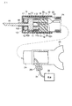
図1は、この発明の第1の実施の形態に係る超音波治療装置の要部を示すもので、超音波振動子を構成する第1及び第2の電歪高分子アクチュエータである第1及び第2のアクチュエータ10,11は、合体自在な第1及び第2のケース12,13内に導電性部材である固定部材14を挟んで対向されて収容配置される。このうち第1のアクチュエータ10は、筒状(チューブ状)の電歪高分子101の両端面に伸縮自在なプラス電極102及びマイナス電極103が分離して設けられ、そのマイナス電極103が上記固定部材14に電気的に接続される。そして、第1のアクチュエータ10の電歪高分子101の内周部には、処置部であるブレード15が挿通される。
(First embodiment)
FIG. 1 shows a main part of an ultrasonic therapy apparatus according to a first embodiment of the present invention. First and second electrostrictive polymer actuators constituting an ultrasonic transducer are shown in FIG. The
このブレード15は、例えば上記固定部材14に一体的に形成され、第1及び第2のケース10,11を金属材料で形成した場合、その外周部に例えば絶縁チューブ16が被覆されて第1のアクチュエータ10との間の絶縁が保たれた状態で、上記第1のケース12の挿通孔121から突出される。この際、第1のアクチュエータ10は、そのプラス電極102と第1のケース12との間に絶縁リング17が介在されて第1のケース12との間の絶縁が保たれる。
The
上記第2のアクチュエータ11は、同様に筒状(チューブ状)の電歪高分子111の外周面及び内周面に伸縮自在なプラス電極112及びマイナス電極113が分離して設けられ、そのマイナス電極113が上記固定部材14に電気的に接続される。そして、この第2のアクチュエータ11は、そのプラス電極112が上記第1のアクチュエータ10のプラス電極102と線材18を介して電気的に接続され、そのマイナス電極113が、上記第1のアクチュエータ10のマイナス電極103と固定部材14を介して電気的に接続される。
Similarly, the
また、上記第2のアクチュエータ11のプラス電極112及びマイナス電極113は、線材18を介して第2のケース13の電極挿通孔131に配したプラス金属板19及びマイナス金属板20に電気的に接続され、このプラス金属板19及びマイナス金属20には、配線ケーブル21が接続される。このプラス金属板19及びマイナス金属板20は、第2のケース13の電極挿通孔131に対して例えばOリング22を介在して密閉収容される。
Further, the plus
上記配線ケーブル21は、上記第1のケース12に支持部材23を介して固定される可撓性を有したシース24内に挿通される。このシース24の基端には、引き出し口251を有した処置操作部25が操作自在に設けられ、この引き出し口251から上記シース24内に挿通された配線ケーブル14が引き出される。この引き出し口251から引き出された配線ケーブル14には、所望の電圧を周期的に供給する電源手段を構成する電源26に接続される。
The
上記第1及び第2のアクチュエータ10,11の電歪高分子101,111は、弾性を有するいわゆるコンデンサーであり、先述した非特許文献2に示されるように誘電エラストマと称され、例えばアクリル、シリコン、ポリウレタン等の樹脂材料で筒状に形成される。そして、プラス電極102,112及びマイナス電極103,113は、例えばフォトリソグラフィーを用いて成膜した電極、あるいはバインダとカーボン微粒子を混ぜて吹き付けたカーボン電極等が用いられる。
The
ここで、上記第1及び第2のアクチュエータ10(11)の駆動原理は、先述した非特許文献3に示されるように、例えば図2に示すように板状の電歪高分子101(111)の両面にプラス電極102(112)及びマイナス電極103(113)を形成して構成した場合、このプラス電極102(112)及びマイナス電極103(113)間に上記電源からの電圧を所望の周期で印加すると、電歪高分子101(111)が、電圧の周期に同期してプラス電極102(112)とマイナス電極103(113)との間に引力が発生し、その電極間方向に収縮されて、その直交する方向に伸展される。この歪率は、図3に示すように印加する電界Eの二乗に比例され、数10%〜300%以上となることが確認される。
Here, the driving principle of the first and second actuators 10 (11) is, for example, as shown in
この動作原理に基づいて、上記第1及び第2のアクチュエータ10,11は、そのプラス電極102,112及びマイナス電極103,113に電源26からの電圧が所望の周期で印加されると、図4に示すようにその第1のアクチュエータ10の電歪高分子101が、電圧の周期に同期して軸方向に収縮されて軸方向と直交する方向に伸展され、その第2のアクチュエータ11の電歪高分子111が、軸方向に伸展されて軸方向と直交する方向に収縮される。これにより、固定部材14に設けられたブレード15は、第1及び第2のアクチュエータ10,11の独立した収縮、伸展動作に連動して軸方向に超音波振動される。
Based on this principle of operation, the first and
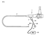
上記ブレード15、第1及び第2のケース12,13、シース24は、図5に示すように内視鏡1の挿入部2の手元側に配される口金3を通して該挿入部2に設けられたチャンネル4に挿入されて装着される(図6参照)。ここで、ブレード15は、挿入部2の撮像レンズ系5に並設されて操作自在に配置される。この状態で、第1及び第2のケース12,13内の第1及び第2のアクチュエータ10,11は、その各電歪高分子101,111のプラス電極102,112及びマイナス電極103,113に対して上記電源26からの電圧が所望の周期で印加されると、上記図4に示すように伸縮駆動、伸展駆動されてブレード15を超音波振動させ、ここに、ブレード15を用いた生体組織の切開・止血等の処置が可能となる。
The
上記構成において、生体組織の切開・止血等の処置を行う場合には、先ず内視鏡1の挿入部2を体腔内に挿入し、その撮像レンズ系5を通して体腔内を撮像してその画像を観察し、患部を確認する。この内視鏡1を介して患部を確認した状態で、ブレード15、第1及び第2のケース12,13、シース24を挿入部2の口金3からチャンネル4内に順に挿入して装着する。
In the above configuration, when performing a treatment such as incision or hemostasis of a living tissue, first, the
次に、患部の観察を行いながら処置操作部25を操作して、ブレード15を前後に移動させて処置部位に合わせ、上記超音波発生操作手段(図示せず)を操作する。ここで、第1及び第2のアクチュエータ10,11の各プラス電極102,112及びマイナス電極103,113には、電源26から電圧が所望の周期で印加される。すると、第1及び第2のアクチュエータ10,11は、その各電歪高分子101,111が電源26からの電圧の供給周期に同期して軸方向に収縮駆動、伸展駆動され、ここに、ブレード15が超音波振動されて生体組織の切開・止血処置が行われる。
Next, the
このように、上記超音波治療装置は、筒状の電歪高分子101,111に対してプラス電極102,112とマイナス電極103,113を配した第1及び第2のアクチュエータ10,11を、固定部材14を介在して対向配置して、この固定部材14に第1のアクチュエータ10を挿通するブレード15を設け、この第1及び第2のアクチュエータ10,11を同期して一方を伸縮駆動して、他方を伸展駆動することにより、固定部材14を介してブレード15を超音波振動させるように構成した。
As described above, the ultrasonic therapy apparatus includes the first and
これによれば、第1及び第2のアクチュエータ10,11は、先述した非特許文献1及び3に示されるようにその一方が数10%〜数100%の歪率で収縮され、その他方が数10%〜数100%の歪率で伸展されてブレード15を超音波振動させることにより、ブレード15を大きな振幅で超音波振動することが可能となり、高い処置能力を有するブレード15を、小型のアクチュエータを用いて実現することが可能となり、装置の小型化を図ることができる。
According to this, one of the first and
また、上記説明では、第1のアクチュエータ10の電歪高分子101の両側面にプラス電極102及びマイナス電極103を設けて、第2のアクチュエータ11の電歪高分子111の内周面及び外周面にプラス電極112及びマイナス電極113を設けて構成した場合について説明したが、これに限るものでなく、その他、図7(a)(b)に示すように第1及び第2のアクチュエータ10,11の電歪高分子101,111内にプラス電極102,112に電気的に接続されるプラス内部電極104,114と、マイナス電極103,113に電気的に接続されるマイナス内部電極105,115を配して構成しても良い。この場合、各プラス内部電極104,114及びマイナス内部電極105,115は、例えば電歪高分子101,111内に複数層が所定の間隔を有して埋設されて各プラス電極102,112及びマイナス電極103,113に電気的に接続される。
In the above description, the
また、ブレード15と固定部材14の配置構成としては、上記説明のようなブレード15を固定部材14に一体形成する構成に限ることなく、その他、例えば図8に示すようにブレード15を固定部材14に螺子締結するように構成しても良く、同様の効果が期待される。
Further, the arrangement configuration of the
即ち、固定部材14には、螺子孔141を第1のアクチュエータ10の電歪高分子101の内周面に対応して設け、ブレード15の基端には、螺子部151を固定部材14の螺子孔141に対応して設ける。そして、ブレード15は、第1のアクチュエータ10の電歪高分子101を挿通させて、その螺子部151を固定部材14の螺子孔141に螺合させて固定配置される。この場合にも、図8中においては、図示していないが上記ブレード15と第1のケース12との間に絶縁チューブ16を介在して絶縁配置し、その第1のアクチュエータ10のプラス電極102と第1のケース12との間に絶縁リング17を介在して絶縁配置することで、さらに良好な効果が得られる(図1参照)。
That is, the fixing
また、上記説明では、異なる電極構造を有する第1及び第2のアクチュエータ10,11を用いて構成したが、これに限ることなく、その他、例えば図9に示すように同一の電極構造を用いて構成することも可能で、同様の効果が期待される。
In the above description, the first and
即ち、図9に示す電極構造は、上記第1及び第2のアクチュエータ10,11の双方の電歪高分子101,11の内周面及び外周面にプラス電極102,112及びマイナス電極103,113が設けられる。そして、これら第1及び第2のアクチュエータ10,11は、その第1のアクチュエータ10に対して上記第2のアクチュエータ11が固定部材14を挟んで対向配置される。
That is, the electrode structure shown in FIG. 9 has
また、第1及び第2のアクチュエータ10,11には、交流電源261、バイアス回路262、反転回路263を有する電源26aが接続され、この電源26aを介して180°の位相差を有する電圧が周期的に供給されて駆動制御される。この場合、第1及び第2のアクチュエータ10,11の各プラス電極102,112は、固定部材14に短絡しないように配され、その各マイナス電極103,113は、固定部材14に導通されて配される。
The first and
そして、第1及び第2のアクチュエータ10,11は、そのプラス電極102,112が、線材264を介して電源26aの反転回路263に電圧が180°の位相差を有するように配線接続される。これにより、第1及び第2のアクチュエータ10,11は、図10に示すように電源26aからバイアス電圧Voが印加されると、交流電圧が0Vの場合、基準(イ),(ハ)となる。そして、第1のアクチュエータ10は、電源16aから電圧Vo+Eoが印加されると、収縮した基準(ロ)の状態となる。他方の、第2のアクチュエータ11は、電圧Vo−Eoが印加されると、基準(ニ)となる。ここで、Vo≧Eoである。
The
上記構成において、第1及び第2のアクチュエータ10,11は、電源26aからの電圧が0Vの状態で、図11(a)の示すように初期状態に設定される。そして、第1及び第2のアクチュエータ10,11は、電源26aを介して第1のアクチュエータ10に電圧Vo−Eoが印加され、第2のアクチュエータ11に電圧Vo+Eoが印加されると、図11(b)に示すように第1のアクチュエータ10が収縮駆動され、第2のアクチュエータ11が伸展駆動される。また、第1のアクチュエータ10に対して電源16aから電圧Vo+Eoが印加され、第2のアクチュエータ11に電圧Vo−Eoが印加されると、図11(c)に示すように第1のアクチュエータ10が伸展駆動され、第2のアクチュエータ11が収縮駆動される。このようにして、第1及び第2のアクチュエータ10,11は、協働してブレード15を軸方向に超音波振動させる。
In the above configuration, the first and
上記第1及び第2のアクチュエータ10,11に配する電極構造としては、その他、図12に示すようにそれぞれプラス電極102,112及びマイナス電極103,113を電歪高分子101,111の両端面に分離配置するように構成しても良い。この場合には、第1及び第2のアクチュエータ10,11の各マイナス電極103,113は、固定部材14に対向して設け、この固定部材14にそれぞれが導通されて取付けられる。また、第1及び第2のアクチュエータ10,11のプラス電極102,112と第1及び第2のケース12,13との間には、上記絶縁リング17がそれぞれ介在されて短絡が防止される。
As the electrode structure disposed on the first and
そして、第1及び第2のアクチュエータ10,11は、各プラス電極102,112及び第2のアクチュエータ11のマイナス電極113が上記電源26aに同様に接続され、同様に180°の位相差を持たせて電圧が供給されて駆動される。
In the first and
なお、上記図8、図9及び図12の電極構造においても、上述したように複数のプラス内部電極104,114及びマイナス内部電極105,115(図7参照)を埋設して構成するようにしても良い。
8, 9, and 12, the plurality of positive
(第2の実施の形態)
図13及び図14は、この発明の第2の実施の形態に係る超音波治療装置を示すもので、上記第1の実施の形態と同様の効果が期待される。但し、この図13及び図14においては、上記第1の実施の形態と同一部分について同一符号を付して、その詳細な説明を省略する。
(Second Embodiment)
FIGS. 13 and 14 show an ultrasonic therapy apparatus according to the second embodiment of the present invention, and the same effects as those of the first embodiment are expected. However, in FIG. 13 and FIG. 14, the same reference numerals are given to the same parts as those in the first embodiment, and the detailed description thereof is omitted.
この第2の実施の形態では、図13に示すように生体組織の粉砕・乳化処置を施すように処置部であるブレード15a及び固定部材14aに挿通孔151a,141aを設けた処置具構造に適用するように構成した。
This second embodiment is applied to a treatment instrument structure in which
即ち、固定部材14aは、図14に示すように上記第1及び第2のアクチュエータ10,11で挟装される。この固定部材14aには、その一方面に上記ブレード15aが突出して設けられ、その他方面に管状のポート27が突出して設けられる。そして、この固定部材に突出されたブレード15aは、上記第1のアクチュエータ10内に挿通されて第1のケース12から突設される。
That is, the fixing
また、上記ポート27は、上記第2のアクチュエーア11内に挿通される。このポート27に対向して第2のケース13には、繋ぎ孔部13aが設けられ、この繋ぎ孔部13aの一端部には、上記ポート27がOリング22aを介在して密封結合される。この繋ぎ孔部13aの他端には、排出チューブ28が取り付けられ、この排出チューブ28は、シース24内に挿通されて、処置操作部25に設けられるチューブ排出口252から引き出されて排出ポンプ29に連結される(図13参照)。
The
上記構成において、生体組織の粉砕・乳化処置を行う場合には、先ず上記内視鏡1の挿入部2を体腔内に挿入し、その撮像レンズ系5を通して体腔内を撮像してその画像を観察し、患部を確認する。この内視鏡1を介して患部を確認した状態で、ブレード15a、第1及び第2のケース12,13、シース24を挿入部2の口金3からチャンネル4内に順に挿入して装着する。
In the above configuration, when performing pulverization / emulsification treatment of the living tissue, first, the
次に、患部の観察を行いながら処置操作部を操作して、ブレード15aを前後に移動させて処置部位に合わせ、上記超音波発生操作手段(図示せず)を操作する。ここで、第1及び第2のアクチュエータ10,11は、その各プラス電極102,112及びマイナス電極間103,113に上述したように電源26から電圧が所望の周期で印加される。すると、第1及び第2のアクチュエータ10,11は、電源26からの電圧の供給周期に同期して軸方向に伸縮され、ここに、ブレード15aが超音波振動されて生体組織の粉砕・乳化処置が行われる。
Next, the treatment operation unit is operated while observing the affected part, the
この際、排出ポンプ29が駆動され、粉砕・乳化処置した生体組織がブレード15aの挿通孔151aに吸引されてポート27、繋ぎ孔部13a及びチューブ28を通して排出ポンプ29から図示しない排出瓶に排出される。
At this time, the
なお、この第2の実施の形態においても、第1及び第2のアクチュエータ10,11の電極構造としては、上記第1の実施の形態において説明したいずれの電極構造のものを用いても適用することが可能であり、いずれの電極構造を用いて構成しても同様の効果が期待される。
In the second embodiment, the electrode structures of the first and
(第3の実施の形態)
図15乃至図18は、この発明の第3の実施の形態に係る超音波治療装置を示すもので、上記第1の実施の形態と同様の効果が期待される。但し、この図15乃至図18においては、上記第1の実施の形態と同一部分について同一符号を付して、その詳細な説明を省略する。
(Third embodiment)
15 to 18 show an ultrasonic therapy apparatus according to the third embodiment of the present invention, and the same effects as those of the first embodiment are expected. However, in FIG. 15 to FIG. 18, the same parts as those in the first embodiment are denoted by the same reference numerals, and detailed description thereof is omitted.
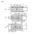
即ち、第3の実施の形態では、図15に示すように生体組織を挟んで強固・切開処置を施すように処置部であるブレード15bの基端部に鉗子片30を開閉自在に配した処置具構造に適用するように構成した。このブレード15bは、図16及び図17に示すように筒状に形成され、その中間部に挿通孔151bを有した隔壁152bが設けられる。そして、このブレード15b内には、筒状の第1及び第2のアクチュエータ10,11が隔壁を挟んで収容配置され、この第1及び第2のアクチュエータ10,11には、筒状の電歪高分子101,111の外周面及び内周面にそれぞれプラス電極102,112及びマイナス電極103,113が設けられる。
That is, in the third embodiment, as shown in FIG. 15, a treatment in which the
また、上記ブレード15b内に内挿された第1及び第2のアクチュエータ10,11の各内周面部、隔壁152bの挿通孔151bには、先端カバー部材31に突設された固定部311が挿通される。この固定部311の先端部には、螺子部312が設けられ、この螺子部312は、カバー押さえ部材32に設けられた螺子孔321に螺合される。これにより、第1のアクチュエータ10は、ブレード15bの隔壁152bとカバー押さえ部材32との間に配され、第2のアクチュエータ11は、ブレード15bの隔壁152bと先端カバー部材31との間に配されてブレード15b内に収容配置される。
Further, a fixing
また、上記先端カバー部材31には、上記鉗子片30の中間部が主軸ピン301を介して回動自在に支持される(図16参照)。この鉗子片30の基端部には、リンク部材33の一端部が支持ピン331を介して回動自在に取付けられる。そして、リンク部材33の基端部には、連結部材34が操作ピン341を介して回動自在に取付けられる。
In addition, an intermediate portion of the
この連結部材34は、先端カバー部材31に設けられる案内溝313に軸方向に移動自在に配される。そして、この連結部材34には、操作ワイヤ35の先端部が取付けられる。この操作ワイヤ35は、上記シース24内に挿通されて上記処置操作部25に移動操作自在に設けられるハンドル36が取付けられ、このハンドル36の摺動操作により矢印A,B方向に移動付勢される。
The connecting
上記鉗子片30は、ハンドル36を操作して操作ワイヤ35が矢印A方向に引き込まれると、リンク部材33が連結部材34、操作ピン341を介して時計方向に回動される。これにより、鉗子片30は、主軸ピン301を中心として反時計方向に回動され、ブレード15bに対して図示しない生体組織を挟んで閉じられる。そして、鉗子片30は、上記ハンドル36が反転操作されると、上記操作ワイヤ35が矢印B方向に移動付勢され、挟持動作と逆に時計方向に回動されて上記ブレード15bから離間される。
When the
また、上記先端カバー部材31には、上記第1及び第2のアクチュエータ10,11のプラス電極102,112及びマイナス電極103,113に接続された配線ケーブル21が挿通され、この配線ケーブル21には、上記電源26aが接続される。これにより、第1及び第2のアクチュエータ10,11は、そのプラス電極102,112及びマイナス電極103,113間に、上述したように電源26aから180°の位相差を有した電圧が印加され、その印加される周期に応じて、図18(a)に示す初期位置から同図(b)あるいは同図(c)に示すように軸方向に収縮、伸展されてブレード15bを超音波振動させる。
A
上記構成において、生体組織の凝固・切開処置を行う場合には、先ず上記内視鏡1の挿入部2を体腔内に挿入し、その撮像レンズ系5を通して体腔内を撮像してその画像を観察し、患部を確認する。この内視鏡1を介して患部を確認した状態で、第1及び第2のアクチュエータ10,11の内挿されたブレード15b、シース24を挿入部2の口金3からチャンネル4内に順に挿入して装着する。
In the above configuration, when coagulation / incision treatment of a living tissue is performed, first, the
ここで、処置操作部25のハンドル36を操作して鉗子片27を開き、ブレード15bと鉗子片30との間に患部が位置するように移動調整して、位置したのを確認した状態で、ハンドル36を反転操作して鉗子片30を閉方向に回動させて鉗子片30とブレード15bとの間で生体組織を挟持する。
Here, the
次に、挟持状態を確認しながら処置操作部25を操作して、電源26aから180°の位相差を有した電圧を所望の周期で第1及び第2のアクチュエータ10,11のプラス電極102,112及びマイナス電極193,113間に印加する。すると、第1及び第2のアクチュエータ10,11は、図18(b)あるいは(c)に示すように電源26aからの電圧の供給周期に同期して軸方向に伸縮され、ここに、ブレード15bが超音波振動されて鉗子片30との間で挟持した生体組織の粉砕・乳化処置が行われる。
Next, the
なお、この第3の実施の形態においても、第1及び第2のアクチュエータ10,11の電極構造としては、上記第1の実施の形態において説明したいずれの電極構造のものを用いても適用することが可能であり、いずれの電極構造を用いて構成しても同様の効果が期待される。
In the third embodiment, the electrode structures of the first and
また、この発明は、上記実施の形態に限ることなく、その他、実施段階ではその要旨を逸脱しない範囲で種々の変形を実施し得ることが可能である。さらに、上記実施の形態には、種々の段階の発明が含まれており、開示される複数の構成要件における適宜な組合せにより種々の発明が抽出され得る。 The present invention is not limited to the above-described embodiment, and various modifications can be made without departing from the scope of the invention at the stage of implementation. Further, the above embodiments include inventions at various stages, and various inventions can be extracted by appropriately combining a plurality of disclosed constituent elements.
例えば実施の形態に示される全構成要件から幾つかの構成要件が削除されても、発明が解決しようとする課題の欄で述べた課題が解決でき、発明の効果で述べられている効果が得られる場合には、この構成要件が削除された構成が発明として抽出され得る。 For example, even if some constituent requirements are deleted from all the constituent requirements shown in the embodiment, the problem described in the column of the problem to be solved by the invention can be solved, and the effect described in the effect of the invention can be obtained. In such a case, a configuration in which this configuration requirement is deleted can be extracted as an invention.
また、この発明は、上記各実施の形態によれば、その他、次のような構成を得ることもできる。 In addition, according to each of the above embodiments, the present invention can also obtain the following configuration.
(付記1)
超音波振動により治療部位を処置する超音波治療装置において、
電歪高分子と2つ以上の電極を有し、前記電極間に電圧が印加されると、前記電歪高分子が伸縮駆動される第1及び第2の電歪高分子アクチュエータと、
前記第1及び第2の電歪高分子アクチュエータ間に介在される固定部材と、
前記固定部材に支持され、前記第1及び第2の電歪高分子アクチュエータの伸縮駆動に連動して超音波振動して治療部位を処置するブレードと、
前記第1及び第2の電歪高分子アクチュエータの各電極間に交流電圧を印加して一方を収縮駆動し、他方を伸展駆動して前記ブレードを前記固定部材を介して超音波振動させる電源と、
を具備することを特徴とする超音波治療装置。
(Appendix 1)
In an ultrasonic therapy apparatus for treating a treatment site by ultrasonic vibration,
First and second electrostrictive polymer actuators having an electrostrictive polymer and two or more electrodes, and when a voltage is applied between the electrodes, the electrostrictive polymer is expanded and contracted;
A fixing member interposed between the first and second electrostrictive polymer actuators;
A blade that is supported by the fixing member and that ultrasonically vibrates in conjunction with the expansion and contraction drive of the first and second electrostrictive polymer actuators to treat the treatment site;
A power source for applying an AC voltage between the electrodes of the first and second electrostrictive polymer actuators to drive one of the electrodes in contraction, and to drive the other to extend and ultrasonically vibrate the blade through the fixing member; ,
An ultrasonic therapy apparatus comprising:
(付記2)
付記1記載の超音波治療装置において、
前記電源は、前記第1及び第2の電歪高分子アクチュエータの電極間に対して180°の位相差を有する電圧を同期して印加することを特徴とする超音波治療装置。
(Appendix 2)
In the ultrasonic therapy apparatus according to
The ultrasonic power supply apparatus according to
(付記3)
内視鏡観察下で超音波振動により治療部位を処置する超音波治療装置において、
電歪高分子と2つ以上の電極を有し、前記電極間に電圧が印加されると、前記電歪高分子が伸縮駆動される第1及び第2の電歪高分子アクチュエータと、
前記第1及び第2の電歪高分子アクチュエータ間に介在される固定部材と、
前記固定部材に支持され、前記第1及び第2の電歪高分子アクチュエータの伸縮駆動に連動して超音波振動して治療部位を処置するブレードと、
前記第1及び第2の電歪高分子アクチュエータの電極間に交流電圧を印加して一方を収縮駆動し、他方を伸展駆動して前記ブレードを前記固定部材を介して超音波振動させる電源と、
前記第1及び第2の電歪高分子アクチュエータを支持する可撓性を有したシースと、
前記シースの基端部に配され、前記電源を制御して第1及び第2の電歪高分子アクチュエータを動作制御する操作部と、
を具備することを特徴とする超音波治療装置。
(Appendix 3)
In an ultrasonic therapy apparatus that treats a treatment site by ultrasonic vibration under endoscopic observation,
First and second electrostrictive polymer actuators having an electrostrictive polymer and two or more electrodes, and when a voltage is applied between the electrodes, the electrostrictive polymer is expanded and contracted;
A fixing member interposed between the first and second electrostrictive polymer actuators;
A blade that is supported by the fixing member and that ultrasonically vibrates in conjunction with the expansion and contraction drive of the first and second electrostrictive polymer actuators to treat the treatment site;
A power source for applying an alternating voltage between the electrodes of the first and second electrostrictive polymer actuators to drive one of them in a contracted manner and to drive the other to extend and to vibrate the blade ultrasonically through the fixing member;
A flexible sheath for supporting the first and second electrostrictive polymer actuators;
An operation unit arranged at a proximal end portion of the sheath and controlling the operation of the first and second electrostrictive polymer actuators by controlling the power source;
An ultrasonic therapy apparatus comprising:
(付記4)
内視鏡観察下で超音波振動により治療部位を処置する超音波治療装置において、
電歪高分子と2つ以上の電極を有し、前記電極間に電圧が印加されると、前記電歪高分子が伸縮駆動される第1及び第2の電歪高分子アクチュエータと、
前記第1及び第2の電歪高分子アクチュエータ間に介在される固定部材と、
前記固定部材に支持され、前記第1及び第2の電歪高分子アクチュエータの伸縮駆動に連動して超音波振動して治療部位を処置するブレードと、
前記第1及び第2の電歪高分子アクチュエータの電極間に交流電圧を印加して一方を収縮駆動し、他方を伸展駆動して前記ブレードを前記固定部材を介して超音波振動させる電源と、
前記第1及び第2の電歪高分子アクチュエータを支持する可撓性を有したシースと、
前記シースの基端部に配され、前記電源を制御して第1及び第2の電歪高分子アクチュエータを動作制御する操作部と、
前記シース内部を通り前記ブレードの内径部に連通されるチューブと、
前記チューブの基端に接続されたポンプと、
を具備することを特徴とする超音波治療装置。
(Appendix 4)
In an ultrasonic therapy apparatus that treats a treatment site by ultrasonic vibration under endoscopic observation,
First and second electrostrictive polymer actuators having an electrostrictive polymer and two or more electrodes, and when a voltage is applied between the electrodes, the electrostrictive polymer is expanded and contracted;
A fixing member interposed between the first and second electrostrictive polymer actuators;
A blade that is supported by the fixing member and that ultrasonically vibrates in conjunction with the expansion and contraction drive of the first and second electrostrictive polymer actuators to treat the treatment site;
A power source for applying an alternating voltage between the electrodes of the first and second electrostrictive polymer actuators to drive one of them in a contracted manner and to drive the other to extend and to vibrate the blade ultrasonically through the fixing member;
A flexible sheath for supporting the first and second electrostrictive polymer actuators;
An operation unit arranged at a proximal end portion of the sheath and controlling the operation of the first and second electrostrictive polymer actuators by controlling the power source;
A tube passing through the inside of the sheath and communicating with the inner diameter portion of the blade;
A pump connected to the proximal end of the tube;
An ultrasonic therapy apparatus comprising:
(付記5)
内視鏡観察下で超音波振動により治療部位を処置する超音波治療装置において、
電歪高分子と2つ以上の電極を有し、前記電極間に電圧が印加されると、前記電歪高分子が伸縮駆動される第1及び第2の電歪高分子アクチュエータと、
前記第1及び第2の電歪高分子アクチュエータが直線上に並設されて内挿され、該第1及び第2の電歪高分子アクチュエータの伸縮に連動して超音波振動して治療部位を処置するブレードと、
前記第1及び第2の電歪高分子アクチュエータの電極間に交流電圧を印加して一方を収縮駆動し、他方を伸展駆動して前記ブレードを超音波振動させる電源と、
前記第1及び第2の電歪高分子アクチュエータを支持する可撓性を有したシースと、
前記シースの基端部に配され、前記電源を制御して第1及び第2の電歪高分子アクチュエータを動作制御する操作部と、
前記第1及び第2の電歪高分子アクチュエータを伸縮駆動自在に支持するもので、前記ブレードに対して選択的に係合される鉗子片を開閉自在に支持する先端カバー部材と、
前記鉗子片を開閉操作して選択的に前記ブレードに係合させる操作ワイヤと、
を具備することを特徴とする超音波治療装置。
(Appendix 5)
In an ultrasonic therapy apparatus that treats a treatment site by ultrasonic vibration under endoscopic observation,
First and second electrostrictive polymer actuators that have an electrostrictive polymer and two or more electrodes, and when a voltage is applied between the electrodes, the electrostrictive polymer is expanded and contracted;
The first and second electrostrictive polymer actuators are arranged side by side in a straight line, and are ultrasonically oscillated in conjunction with the expansion and contraction of the first and second electrostrictive polymer actuators to define a treatment site. A blade to be treated;
A power source for applying an alternating voltage between the electrodes of the first and second electrostrictive polymer actuators to drive one of them in contraction and to drive the other to extend and ultrasonically vibrate the blade;
A flexible sheath for supporting the first and second electrostrictive polymer actuators;
An operation unit arranged at a proximal end portion of the sheath and controlling the operation of the first and second electrostrictive polymer actuators by controlling the power source;
A tip cover member that supports the first and second electrostrictive polymer actuators so as to be extendable and retractable, and supports a forceps piece that is selectively engaged with the blade so as to be opened and closed;
An operation wire for selectively engaging the blade by opening and closing the forceps piece;
An ultrasonic therapy apparatus comprising:
(付記6)
付記5記載の超音波治療装置において、
前記ブレードは、筒状の内周部に挿通孔を有する隔壁が設けられ、この隔壁を挟んで前記第1及び第2の電歪高分子アクチュエータを対向配置し、前記先端カバー部材に設けた連結部を第1及び第2の電歪高分子アクチュエータ、前記隔壁の挿通孔に挿通させて前記第1及び第2の電歪高分子アクチュエータを前記先端カバー部材に組付けたことを特徴とする超音波治療装置。
(Appendix 6)
In the ultrasonic therapy apparatus according to
The blade is provided with a partition wall having an insertion hole in a cylindrical inner peripheral portion, the first and second electrostrictive polymer actuators are arranged opposite to each other with the partition wall interposed therebetween, and a connection provided on the tip cover member The first and second electrostrictive polymer actuators are inserted into the insertion holes of the first and second electrostrictive polymer actuators and the partition wall, and the first and second electrostrictive polymer actuators are assembled to the tip cover member. Sonic therapy device.
1…内視鏡、2…挿入部、3…口金、4…チャンネル、5…撮像レンズ系、10,11…第1及び第2のアクチュエータ、101…電歪高分子、102,112…プラス電極、103,113…マイナス電極、104,114…プラス内部電極、105,115…マイナス内部電極、11…電歪高分子、12,13…第1及び第2のケース、121…挿通孔、131…電極挿通孔、13a…繋ぎ孔部、14,14a…固定部材、141a…挿通孔、15,15a,15b…ブレード、151…螺子部、151a…挿通孔、151b…挿通孔、152b…隔壁、16…絶縁チューブ、17…絶縁リング、18…線材、19…プラス金属板、20…マイナス金属板、21…配線ケーブル、22,22a…Oリング、23…支持部材、24…シース、25…処置操作部、251…引き出し口、252…チューブ排出口、26,26a…電源、261…交流電源、262…バイアス回路、263…反転回路、264…線材、27…ポート、28…Oリング、29…排出ポンプ、30…鉗子片、301…主軸ピン、31…先端カバー部材、311…固定部、312…螺子部、32…カバー押さえ部材、321…螺子孔、33…リンク部材、331…支持ピン、34…連結部材、35…操作ワイヤ、36…ハンドル。
DESCRIPTION OF
Claims (7)
前記第1及び第2のアクチュエータ間に介在される固定部材と、
前記固定部材に支持され、前記第1及び第2のアクチュエータの伸縮駆動に連動して超音波振動して治療部位を処置する処置部と、
前記第1及び第2のアクチュエータの電極間に電圧を印加して一方を収縮駆動して他方を伸展駆動し、前記処置部を前記固定部材を介して超音波振動させる電源手段と、
を具備することを特徴とする超音波治療装置。 When an electrode is disposed on the electrostrictive polymer, and a voltage is applied between the electrodes, the first and second actuators are driven to extend and contract the electrostrictive polymer;
A fixing member interposed between the first and second actuators;
A treatment unit supported by the fixing member and ultrasonically oscillating in conjunction with the expansion and contraction drive of the first and second actuators to treat the treatment site;
Power supply means for applying a voltage between the electrodes of the first and second actuators to drive one of the actuators contractively and drive the other to extend, and ultrasonically vibrate the treatment portion via the fixing member;
An ultrasonic therapy apparatus comprising:
電歪高分子と2つ以上の電極を有し、前記電極間に電圧が印加されると、前記電歪高分子が伸縮駆動される第1及び第2の電歪高分子アクチュエータと、
前記第1及び第2の電歪高分子アクチュエータ間に介在される固定部材と、
前記固定部材に支持され、前記第1及び第2の電歪高分子アクチュエータの伸縮駆動に連動して超音波振動して治療部位を処置するブレードと、
前記第1及び第2の電歪高分子アクチュエータの各電極間に交流電圧を印加して一方を収縮駆動し、他方を伸展駆動して前記ブレードを前記固定部材を介して超音波振動させる電源と、
を具備することを特徴とする超音波治療装置。 In an ultrasonic therapy apparatus for treating a treatment site by ultrasonic vibration,
First and second electrostrictive polymer actuators having an electrostrictive polymer and two or more electrodes, and when a voltage is applied between the electrodes, the electrostrictive polymer is expanded and contracted;
A fixing member interposed between the first and second electrostrictive polymer actuators;
A blade that is supported by the fixing member and that ultrasonically vibrates in conjunction with the expansion and contraction drive of the first and second electrostrictive polymer actuators to treat the treatment site;
A power source for applying an AC voltage between the electrodes of the first and second electrostrictive polymer actuators to drive one of the electrodes in contraction, and to drive the other to extend and ultrasonically vibrate the blade through the fixing member; ,
An ultrasonic therapy apparatus comprising:
電歪高分子と2つ以上の電極を有し、前記電極間に電圧が印加されると、前記電歪高分子が伸縮駆動される第1及び第2の電歪高分子アクチュエータと、First and second electrostrictive polymer actuators having an electrostrictive polymer and two or more electrodes, and when a voltage is applied between the electrodes, the electrostrictive polymer is expanded and contracted;
前記第1及び第2の電歪高分子アクチュエータ間に介在される固定部材と、A fixing member interposed between the first and second electrostrictive polymer actuators;
前記固定部材に支持され、前記第1及び第2の電歪高分子アクチュエータの伸縮駆動に連動して超音波振動して治療部位を処置するブレードと、A blade that is supported by the fixing member and that ultrasonically vibrates in conjunction with the expansion and contraction drive of the first and second electrostrictive polymer actuators to treat the treatment site;
前記第1及び第2の電歪高分子アクチュエータの電極間に交流電圧を印加して一方を収縮駆動し、他方を伸展駆動して前記ブレードを前記固定部材を介して超音波振動させる電源と、A power source for applying an alternating voltage between the electrodes of the first and second electrostrictive polymer actuators to drive one of them in a contracted manner and to drive the other to extend and to vibrate the blade ultrasonically through the fixing member;
前記第1及び第2の電歪高分子アクチュエータを支持する可撓性を有したシースと、A flexible sheath for supporting the first and second electrostrictive polymer actuators;
前記シースの基端部に配され、前記電源を制御して第1及び第2の電歪高分子アクチュエータを動作制御する操作部と、An operation unit arranged at a proximal end portion of the sheath and controlling the operation of the first and second electrostrictive polymer actuators by controlling the power source;
を具備することを特徴とする超音波治療装置。An ultrasonic therapy apparatus comprising:
電歪高分子と2つ以上の電極を有し、前記電極間に電圧が印加されると、前記電歪高分子が伸縮駆動される第1及び第2の電歪高分子アクチュエータと、First and second electrostrictive polymer actuators having an electrostrictive polymer and two or more electrodes, and when a voltage is applied between the electrodes, the electrostrictive polymer is expanded and contracted;
前記第1及び第2の電歪高分子アクチュエータ間に介在される固定部材と、A fixing member interposed between the first and second electrostrictive polymer actuators;
前記固定部材に支持され、前記第1及び第2の電歪高分子アクチュエータの伸縮駆動に連動して超音波振動して治療部位を処置するブレードと、A blade that is supported by the fixing member and that ultrasonically vibrates in conjunction with the expansion and contraction drive of the first and second electrostrictive polymer actuators to treat the treatment site;
前記第1及び第2の電歪高分子アクチュエータの電極間に交流電圧を印加して一方を収縮駆動し、他方を伸展駆動して前記ブレードを前記固定部材を介して超音波振動させる電源と、A power source for applying an alternating voltage between the electrodes of the first and second electrostrictive polymer actuators to drive one of them in a contracted manner and to drive the other to extend and to vibrate the blade ultrasonically through the fixing member;
前記第1及び第2の電歪高分子アクチュエータを支持する可撓性を有したシースと、A flexible sheath for supporting the first and second electrostrictive polymer actuators;
前記シースの基端部に配され、前記電源を制御して第1及び第2の電歪高分子アクチュエータを動作制御する操作部と、An operation unit arranged at a proximal end portion of the sheath and controlling the operation of the first and second electrostrictive polymer actuators by controlling the power source;
前記シース内部を通り前記ブレードの内径部に連通されるチューブと、A tube passing through the inside of the sheath and communicating with the inner diameter portion of the blade;
前記チューブの基端に接続されたポンプと、A pump connected to the proximal end of the tube;
を具備することを特徴とする超音波治療装置。An ultrasonic therapy apparatus comprising:
電歪高分子と2つ以上の電極を有し、前記電極間に電圧が印加されると、前記電歪高分子が伸縮駆動される第1及び第2の電歪高分子アクチュエータと、First and second electrostrictive polymer actuators having an electrostrictive polymer and two or more electrodes, and when a voltage is applied between the electrodes, the electrostrictive polymer is expanded and contracted;
前記第1及び第2の電歪高分子アクチュエータが直線上に並設されて内挿され、該第1及び第2の電歪高分子アクチュエータの伸縮に連動して超音波振動して治療部位を処置するブレードと、The first and second electrostrictive polymer actuators are arranged side by side in a straight line, and are ultrasonically oscillated in conjunction with the expansion and contraction of the first and second electrostrictive polymer actuators to define a treatment site. A blade to treat,
前記第1及び第2の電歪高分子アクチュエータの電極間に交流電圧を印加して一方を収縮駆動し、他方を伸展駆動して前記ブレードを超音波振動させる電源と、A power source for applying an alternating voltage between the electrodes of the first and second electrostrictive polymer actuators to drive one of them in contraction and to drive the other to extend and ultrasonically vibrate the blade;
前記第1及び第2の電歪高分子アクチュエータを支持する可撓性を有したシースと、A flexible sheath for supporting the first and second electrostrictive polymer actuators;
前記シースの基端部に配され、前記電源を制御して第1及び第2の電歪高分子アクチュエータを動作制御する操作部と、An operation unit arranged at a proximal end portion of the sheath and controlling the operation of the first and second electrostrictive polymer actuators by controlling the power source;
前記第1及び第2の電歪高分子アクチュエータを伸縮駆動自在に支持するもので、前記ブレードに対して選択的に係合される鉗子片を開閉自在に支持する先端カバー部材と、A tip cover member that supports the first and second electrostrictive polymer actuators so as to be extendable and retractable, and supports a forceps piece that is selectively engaged with the blade so as to be freely opened and closed;
前記鉗子片を開閉操作して選択的に前記ブレードに係合させる操作ワイヤと、An operation wire for selectively engaging the blade by opening and closing the forceps piece;
を具備することを特徴とする超音波治療装置。An ultrasonic therapy apparatus comprising:
Priority Applications (4)
| Application Number | Priority Date | Filing Date | Title |
|---|---|---|---|
| JP2005314324A JP4542499B2 (en) | 2005-10-28 | 2005-10-28 | Ultrasonic therapy device |
| CN2006800360180A CN101277652B (en) | 2005-10-28 | 2006-10-26 | Ultrasonic treatment device |
| PCT/JP2006/321416 WO2007049717A1 (en) | 2005-10-28 | 2006-10-26 | Ultrasonic treatment device |
| US12/109,744 US8226676B2 (en) | 2005-10-28 | 2008-04-25 | Ultrasonic surgical instrument |
Applications Claiming Priority (1)
| Application Number | Priority Date | Filing Date | Title |
|---|---|---|---|
| JP2005314324A JP4542499B2 (en) | 2005-10-28 | 2005-10-28 | Ultrasonic therapy device |
Publications (3)
| Publication Number | Publication Date |
|---|---|
| JP2007117447A JP2007117447A (en) | 2007-05-17 |
| JP2007117447A5 JP2007117447A5 (en) | 2007-08-16 |
| JP4542499B2 true JP4542499B2 (en) | 2010-09-15 |
Family
ID=37967827
Family Applications (1)
| Application Number | Title | Priority Date | Filing Date |
|---|---|---|---|
| JP2005314324A Expired - Fee Related JP4542499B2 (en) | 2005-10-28 | 2005-10-28 | Ultrasonic therapy device |
Country Status (4)
| Country | Link |
|---|---|
| US (1) | US8226676B2 (en) |
| JP (1) | JP4542499B2 (en) |
| CN (1) | CN101277652B (en) |
| WO (1) | WO2007049717A1 (en) |
Families Citing this family (7)
| Publication number | Priority date | Publication date | Assignee | Title |
|---|---|---|---|---|
| DE102008041682A1 (en) * | 2008-08-29 | 2010-03-04 | Robert Bosch Gmbh | Electric hand tool |
| JP5385930B2 (en) * | 2011-02-22 | 2014-01-08 | 富士フイルム株式会社 | Ultrasonic surgical device |
| US9852385B2 (en) * | 2011-12-08 | 2017-12-26 | Sap Se | Processing of business object identifiers in master data integration scenarios involving non-local identifiers |
| JP5782177B2 (en) * | 2012-03-15 | 2015-09-24 | アルプス電気株式会社 | Drive device using polymer actuator |
| EP2910175A4 (en) * | 2012-12-04 | 2016-06-01 | Olympus Corp | Scanning endoscope system |
| US10231747B2 (en) * | 2013-09-20 | 2019-03-19 | Ethicon Llc | Transducer features for ultrasonic surgical instrument |
| CN112438781B (en) * | 2020-11-24 | 2022-02-18 | 常州安康医疗器械有限公司 | Negative pressure suction type ultrasonic knife |
Citations (5)
| Publication number | Priority date | Publication date | Assignee | Title |
|---|---|---|---|---|
| JPH0299046A (en) * | 1988-10-07 | 1990-04-11 | Olympus Optical Co Ltd | Ultrasonic treatment apparatus |
| JPH0747135A (en) * | 1993-02-05 | 1995-02-21 | Joe W & Dorothy Dorsett Brown Found:The | Ultrasonic angioplasty baloon catheter |
| JP2001057983A (en) * | 1999-08-23 | 2001-03-06 | Olympus Optical Co Ltd | Ultrasonic treating tool |
| JP2001286162A (en) * | 2000-03-31 | 2001-10-12 | Keiwa Ryu | Drive device utilizing electrostrictive expansion and construction material |
| US20020151825A1 (en) * | 2001-04-12 | 2002-10-17 | Pearl Technology Holdings, Llc | Ultrasound plaque emulsion device |
Family Cites Families (11)
| Publication number | Priority date | Publication date | Assignee | Title |
|---|---|---|---|---|
| US4728843A (en) * | 1985-11-11 | 1988-03-01 | Taga Electric Co., Ltd. | Ultrasonic vibrator and drive control method thereof |
| JPH0268047A (en) * | 1988-09-05 | 1990-03-07 | Sumitomo Bakelite Co Ltd | Implement for surgery operation |
| JPH08117240A (en) * | 1994-10-20 | 1996-05-14 | Alps Electric Co Ltd | Therapeutic device |
| US6063098A (en) * | 1996-12-23 | 2000-05-16 | Houser; Kevin | Articulable ultrasonic surgical apparatus |
| JPH1156867A (en) * | 1997-08-12 | 1999-03-02 | Yasuto Takeuchi | Ultrasonic medical operation system |
| US6068647A (en) | 1997-10-10 | 2000-05-30 | Ethicon Endo-Surgery, Inc. | Ultrasonic clamp coagulator apparatus having improved clamp arm tissue pad |
| US6214017B1 (en) | 1998-09-25 | 2001-04-10 | Sherwood Services Ag | Ultrasonic surgical apparatus |
| US6458142B1 (en) * | 1999-10-05 | 2002-10-01 | Ethicon Endo-Surgery, Inc. | Force limiting mechanism for an ultrasonic surgical instrument |
| US6605084B2 (en) * | 2000-03-24 | 2003-08-12 | Transurgical, Inc. | Apparatus and methods for intrabody thermal treatment |
| WO2004012615A1 (en) * | 2002-08-02 | 2004-02-12 | Olympus Corporation | Ultrasonic treatment apparatus |
| JP4127810B2 (en) * | 2003-09-19 | 2008-07-30 | オリンパス株式会社 | Ultrasonic vibrator and manufacturing method thereof |
-
2005
- 2005-10-28 JP JP2005314324A patent/JP4542499B2/en not_active Expired - Fee Related
-
2006
- 2006-10-26 WO PCT/JP2006/321416 patent/WO2007049717A1/en active Application Filing
- 2006-10-26 CN CN2006800360180A patent/CN101277652B/en not_active Expired - Fee Related
-
2008
- 2008-04-25 US US12/109,744 patent/US8226676B2/en not_active Expired - Fee Related
Patent Citations (5)
| Publication number | Priority date | Publication date | Assignee | Title |
|---|---|---|---|---|
| JPH0299046A (en) * | 1988-10-07 | 1990-04-11 | Olympus Optical Co Ltd | Ultrasonic treatment apparatus |
| JPH0747135A (en) * | 1993-02-05 | 1995-02-21 | Joe W & Dorothy Dorsett Brown Found:The | Ultrasonic angioplasty baloon catheter |
| JP2001057983A (en) * | 1999-08-23 | 2001-03-06 | Olympus Optical Co Ltd | Ultrasonic treating tool |
| JP2001286162A (en) * | 2000-03-31 | 2001-10-12 | Keiwa Ryu | Drive device utilizing electrostrictive expansion and construction material |
| US20020151825A1 (en) * | 2001-04-12 | 2002-10-17 | Pearl Technology Holdings, Llc | Ultrasound plaque emulsion device |
Also Published As
| Publication number | Publication date |
|---|---|
| US20080208232A1 (en) | 2008-08-28 |
| WO2007049717A1 (en) | 2007-05-03 |
| JP2007117447A (en) | 2007-05-17 |
| US8226676B2 (en) | 2012-07-24 |
| CN101277652A (en) | 2008-10-01 |
| CN101277652B (en) | 2011-02-09 |
Similar Documents
| Publication | Publication Date | Title |
|---|---|---|
| JP4542499B2 (en) | Ultrasonic therapy device | |
| JP3999715B2 (en) | Ultrasonic treatment device | |
| CN109640846B (en) | Tissue loading of surgical instruments | |
| CN109561913B (en) | Ultrasonic assembly for use with ultrasonic surgical instruments | |
| JP4657082B2 (en) | Ultrasonic therapy device | |
| CN106413595B (en) | Ultrasound pincers | |
| US9566079B2 (en) | Single probe with disturber | |
| CN108377642A (en) | Activation feature structure for ultrasonic surgical instrument | |
| HRP990264A2 (en) | Neurosurgical endoscopic ultrasonic contact probe | |
| US20150088123A1 (en) | Liquid ejecting apparatus for medical treatment | |
| US10736686B2 (en) | Surgical device employing a cantilevered beam dissector | |
| US9180315B2 (en) | Ultrasonic treatment device and probe unit | |
| JP6393382B2 (en) | Medical equipment | |
| US20150088130A1 (en) | Liquid ejecting apparatus for medical treatment | |
| JP6280633B2 (en) | Friction drive actuator | |
| EP2095779B1 (en) | Surgical treatment apparatus | |
| JP2014000525A (en) | Ultrasonic treatment device and ultrasonic treatment system | |
| JPH06326369A (en) | Actuator | |
| JP6084100B2 (en) | Ultrasonic treatment device | |
| JP2006006390A (en) | Ultrasonic treatment apparatus | |
| WO2016075745A1 (en) | Medical treatment apparatus |
Legal Events
| Date | Code | Title | Description |
|---|---|---|---|
| A521 | Written amendment |
Free format text: JAPANESE INTERMEDIATE CODE: A523 Effective date: 20070702 |
|
| A621 | Written request for application examination |
Free format text: JAPANESE INTERMEDIATE CODE: A621 Effective date: 20070702 |
|
| TRDD | Decision of grant or rejection written | ||
| A01 | Written decision to grant a patent or to grant a registration (utility model) |
Free format text: JAPANESE INTERMEDIATE CODE: A01 Effective date: 20100615 |
|
| A01 | Written decision to grant a patent or to grant a registration (utility model) |
Free format text: JAPANESE INTERMEDIATE CODE: A01 |
|
| A61 | First payment of annual fees (during grant procedure) |
Free format text: JAPANESE INTERMEDIATE CODE: A61 Effective date: 20100625 |
|
| R151 | Written notification of patent or utility model registration |
Ref document number: 4542499 Country of ref document: JP Free format text: JAPANESE INTERMEDIATE CODE: R151 |
|
| FPAY | Renewal fee payment (event date is renewal date of database) |
Free format text: PAYMENT UNTIL: 20130702 Year of fee payment: 3 |
|
| S111 | Request for change of ownership or part of ownership |
Free format text: JAPANESE INTERMEDIATE CODE: R313111 |
|
| R350 | Written notification of registration of transfer |
Free format text: JAPANESE INTERMEDIATE CODE: R350 |
|
| S531 | Written request for registration of change of domicile |
Free format text: JAPANESE INTERMEDIATE CODE: R313531 |
|
| R350 | Written notification of registration of transfer |
Free format text: JAPANESE INTERMEDIATE CODE: R350 |
|
| R250 | Receipt of annual fees |
Free format text: JAPANESE INTERMEDIATE CODE: R250 |
|
| LAPS | Cancellation because of no payment of annual fees |