JP4655701B2 - Position detection device, blur correction device, and lens barrel - Google Patents
Position detection device, blur correction device, and lens barrel Download PDFInfo
- Publication number
- JP4655701B2 JP4655701B2 JP2005070775A JP2005070775A JP4655701B2 JP 4655701 B2 JP4655701 B2 JP 4655701B2 JP 2005070775 A JP2005070775 A JP 2005070775A JP 2005070775 A JP2005070775 A JP 2005070775A JP 4655701 B2 JP4655701 B2 JP 4655701B2
- Authority
- JP
- Japan
- Prior art keywords
- magnetic
- unit
- generation unit
- magnetic generation
- magnetism
- Prior art date
- Legal status (The legal status is an assumption and is not a legal conclusion. Google has not performed a legal analysis and makes no representation as to the accuracy of the status listed.)
- Expired - Fee Related
Links
Images


Landscapes
- Measurement Of Length, Angles, Or The Like Using Electric Or Magnetic Means (AREA)
- Adjustment Of Camera Lenses (AREA)
Description
本発明は、所定の対象物の変位を検出する位置検出装置、及び、このような位置検出装置を備えたブレ補正装置及びレンズ鏡筒に関するものである。 The present invention relates to a position detection device that detects a displacement of a predetermined object, and a shake correction device and a lens barrel that include such a position detection device.
カメラの撮影用光学系等に用いられるブレ補正装置は、光学系の一部に含まれるブレ補正光学系を、光軸と略直交方向に変位させることによって、その結像面における被写体像のブレ(像ブレ)を低減するものである。
ブレ補正装置は、通常撮影時におけるカメラの縦振れ(ピッチング)及び横振れ(ヨーイング)に対する補正を行うことが一般的であり、この場合、ブレ補正光学系は、各方向のブレに対応して、直交2軸方向にそれぞれ平行移動する。
A shake correction apparatus used in a camera photographing optical system or the like displaces a shake correction optical system included in a part of the optical system in a direction substantially orthogonal to the optical axis, thereby blurring a subject image on its imaging plane. (Image blur) is reduced.
The shake correction device generally corrects the vertical shake (pitching) and lateral shake (yawing) of the camera during normal shooting. In this case, the shake correction optical system corresponds to the shake in each direction. , And move in parallel in two orthogonal directions.
ブレ補正装置は、その補正精度を確保するため、ブレ補正光学系の位置を正確に検出することが求められる。
従来、ブレ補正装置は、ブレ補正光学系の位置を検出するために、ホール素子等の磁気検出素子を利用した位置検出装置を用いることが知られている(例えば、特許文献1)。
このような位置検出装置は、磁気検出素子とマグネットとを備え、この一方をブレ補正光学系に追従して移動するようにし、他方をレンズ鏡筒側に固定したものであって、これらが相対移動する際に磁気検出素子が検出する磁場強度の変化に基づいて位置検出を行うものである。
The shake correction device is required to accurately detect the position of the shake correction optical system in order to ensure the correction accuracy.
Conventionally, it is known that a shake correction device uses a position detection device using a magnetic detection element such as a Hall element in order to detect the position of a shake correction optical system (for example, Patent Document 1).
Such a position detection device includes a magnetic detection element and a magnet, one of which moves following the blur correction optical system, and the other is fixed to the lens barrel side. Position detection is performed based on a change in magnetic field intensity detected by the magnetic detection element when moving.
上述した位置検出装置は、通常、磁気検出素子に対するマグネットの磁化方向(N極とS極との配列方向)における位置を検出するものであるが、ブレ補正光学系は、直交2軸方向にそれぞれ移動するために、位置検出装置の磁気検出素子とマグネットとは、本来の検出方向とは異なる方向にも相対移動することになる。
位置検出装置は、磁気検出素子とマグネットとが、マグネットの磁化方向と直交する方向に相対移動した場合であっても、磁気検出素子が検出する磁場強度が変化するから、本来の検出方向における位置検出において誤差が生じてしまう。
Since the magnetic field intensity detected by the magnetic detection element changes even when the magnetic detection element and the magnet move relative to each other in a direction perpendicular to the magnetization direction of the magnet, the position detection device has a position in the original detection direction. An error occurs in detection.
本発明の課題は、検出誤差を低減した位置検出装置、及び、このような位置検出装置を備えたブレ補正装置及びレンズ鏡筒を提供することである。 An object of the present invention is to provide a position detection device with reduced detection error, and a blur correction device and a lens barrel that include such a position detection device.
本発明は、以下のような解決手段により、前記課題を解決する。なお、理解を容易にするために、本発明の実施例に対応する符号を付して説明するが、これに限定されるものではない。 The present invention solves the above problems by the following means. In addition, in order to make an understanding easy, although the code | symbol corresponding to the Example of this invention is attached | subjected and demonstrated, it is not limited to this.
請求項1に記載の発明は、第1方向に沿った一端側に、前記第1方向と略直交する第2方向に離間して複数のN極(121,122)が備えられ、前記第1方向に沿った他端側に、前記第2方向に離間して複数のS極が備えられ、前記複数のN極(121,122)の間、及び、前記複数のS極の間に、前記第1方向に延在する無磁化領域が備えられた相対移動部(120)と、前記相対移動部(120)に対して前記第1方向及び前記第2方向に相対移動可能に前記相対移動部(120)と対向して備えられ、前記N極(121,122)及び前記S極の磁気を検出する磁気検出部(110)とを含み、前記相対移動部(120)と前記磁気検出部(110)との前記第1方向の相対位置を検出することを特徴とする位置検出装置(100)である。 In the first aspect of the present invention, a plurality of N poles (121, 122) are provided on one end side along the first direction so as to be spaced apart from each other in a second direction substantially orthogonal to the first direction . A plurality of S poles spaced apart in the second direction are provided on the other end side along the direction, and between the plurality of N poles (121, 122) and between the plurality of S poles , A relative movement part (120) provided with a non-magnetized region extending in a first direction, and the relative movement part movable relative to the relative movement part (120) in the first direction and the second direction. (120) and a magnetic detection unit (110) that detects the magnetism of the N pole (121, 122) and the S pole, and includes the relative movement unit (120) and the magnetic detection unit ( position detecting device characterized that you detect the relative position of said first direction and 110) (100 It is.
請求項2に記載の発明は、第1方向に沿った一端側に、前記第1方向と略直交する第2方向に離間して複数のN極(121,122)が備えられ、前記第1方向に沿った他端側に、前記第2方向に離間して複数のS極が備えられ、前記複数のN極(121,122)の間、及び、前記複数のS極の間に、前記複数のN極(121,122)及び前記複数のS極よりも磁束密度が低い低磁化領域(300)が備えられた相対移動部(120)と、前記相対移動部(120)に対して前記第1方向及び前記第2方向に相対移動可能に前記相対移動部(120)と対向して備えられ、前記N極(121,122)及び前記S極の磁気を検出する磁気検出部(110)とを含み、前記相対移動部(120)と前記磁気検出部(110)との前記第1方向の相対位置を検出することを特徴とする位置検出装置(300)である。 According to a second aspect of the present invention, a plurality of N poles (121, 122) are provided on one end side along the first direction so as to be spaced apart from each other in a second direction substantially orthogonal to the first direction. A plurality of S poles spaced apart in the second direction are provided on the other end side along the direction, and between the plurality of N poles (121, 122) and between the plurality of S poles, A relative movement part (120) provided with a plurality of N poles (121, 122) and a low magnetization region (300) having a magnetic flux density lower than that of the plurality of S poles, and the relative movement part (120) A magnetic detection unit (110) provided to face the relative movement unit (120) so as to be relatively movable in the first direction and the second direction, and detects the magnetism of the N poles (121, 122) and the S poles. The first way of the relative movement part (120) and the magnetic detection part (110) A position detecting device which is characterized that you detect the relative position (300).
請求項3に記載の発明は、第1方向に沿った一端側にN極(121,122)が備えられ、前記第1方向に沿った他端側にS極が備えられ、前記N極(121,122)及び前記S極の磁気検出部(110)に対向する面に前記第1方向と平行な凹部(420)が備えられた相対移動部(420)と、前記相対移動部(420)に対して前記第1方向及び前記第1方向と略直交する第2方向に相対移動可能に前記相対移動部(420)と対向して備えられ、前記N極(121,122)及び前記S極の磁気を検出する前記磁気検出部(110)とを含み、前記相対移動部(420)と前記磁気検出部(110)との前記第1方向の相対位置を検出することを特徴とする位置検出装置(400)である。 According to a third aspect of the present invention, an N pole (121, 122) is provided on one end side along the first direction, an S pole is provided on the other end side along the first direction, and the N pole ( 121, 122) and the S magnetic detector of the pole (110) parallel to the first direction to the surface facing the recess (420) is provided relative movement section (420), the relative movement unit (420 ) To be opposed to the relative movement part (420) so as to be relatively movable in the first direction and a second direction substantially orthogonal to the first direction, and the N pole (121, 122) and the S and a said magnetic detector for detecting a pole of the magnetic (110), a position and detecting the relative position of said first direction of said magnetic detection unit and the relative moving section (420) (110) A detection device (400).
請求項4に記載の発明は、ブレ補正光学系(2)と、前記ブレ補正光学系(2)を、その光軸に直交する平面に略沿って移動可能に支持するブレ補正光学系(2)支持部と、前記ブレ補正光学系(2)を前記ブレ補正光学系(2)支持部に対してその光軸と略直交する方向に駆動する駆動部(4,5)と、前記ブレ補正光学系(2)及び前記ブレ補正光学系(2)支持部の一方に固定された磁気検出部(110)及び他方に固定された相対移動部(120)を有する請求項1から請求項3までのいずれか1項に記載の位置検出装置(100)とを備えるブレ補正装置である。
請求項5に記載の発明は、第1方向に沿った一端側に備えられ、磁気を発生させる第1の磁気発生部と、前記第1方向と交差する第2方向に前記第1の磁気発生部と間隔を隔てて前記一端側に備えられ、前記第1の磁気発生部と同一極性の磁気を発生させる第2の磁気発生部と、前記第1方向に沿った他端側に備えられ前記第1の磁気発生部とは異なる極性の磁気を発生させる第3の磁気発生部と、前記第2方向に前記第3の磁気発生部と間隔を隔てて前記他端側に備えられ、前記第3の磁気発生部と同一極性の磁気を発生させる第4の磁気発生部と、前記第1の磁気発生部と前記第2の磁気発生部との間に備えられ、前記第1の磁気発生部および前記第2の磁気発生部よりも低い磁気を発生する第1低磁気部と、前記第3の磁気発生部と前記第4の磁気発生部との間に備えられ、前記第3の磁気発生部および前記第4の磁気発生部よりも低い磁気を発生する第2低磁気部と、前記第1の磁気発生部、前記第2の磁気発生部、前記第3の磁気発生部および前記第4の磁気発生部と前記第1方向及び前記第2方向に相対移動可能であり、前記第1の磁気発生部、前記第2の磁気発生部、前記第3の磁気発生部および前記第4の磁気発生部から生じる前記磁気を検出する磁気検出部(110)とを備え、前記磁気検出部(110)と、前記第1の磁気発生部、前記第2の磁気発生部、前記第3の磁気発生部および前記第4の磁気発生部との前記第1方向の相対位置を検出することを特徴とする位置検出装置(100)である。
請求項6に記載の発明は、請求項5に記載の位置検出装置(100)において、前記磁気検出部(110)は、前記第1低磁気部及び前記第2低磁気部と対向して前記第1方向に沿って前記第1の磁気発生部、前記第2の磁気発生部、前記第3の磁気発生部および前記第4の磁気発生部と相対移動可能であり、前記第1の磁気発生部、前記第2の磁気発生部、前記第3の磁気発生部および前記第4の磁気発生部は、前記第1方向に沿って前記磁気検出部(110)と相対移動するとき、前記磁気検出部(110)で検出される前記磁気が前記第1方向の相対移動量に対して所定の出力特性で変化するように配置されていることを特徴とする位置検出装置(100)である。
請求項7に記載の発明は、請求項5又は請求項6に記載の位置検出装置(100)において、前記第1低磁気部及び前記第2低磁気部は、前記第2方向に前記第1の磁気発生部、前記第2の磁気発生部、前記第3の磁気発生部および前記第4の磁気発生部と前記磁気検出部(110)とが相対移動するとき、前記磁気検出部(110)で検出される前記磁気の位置検出誤差が抑制されるように配置されていることを特徴とする位置検出装置(100)である。
請求項8に記載の発明は、請求項5から請求項7までの何れか1項に記載された位置検出装置(100)を備えたことを特徴とするブレ補正装置である。
請求項9に記載の発明は、請求項4又は請求項8に記載されたブレ補正装置を備えたことを特徴とするレンズ鏡筒である。
請求項10に記載の発明は、ブレ補正光学系(2)と、前記ブレ補正光学系(2)を、その光軸に直交するとともに互いに直交するX軸とY軸とで構成されるXY平面に略沿って移動可能に支持するブレ補正光学系(2)支持部と、前記ブレ補正光学系(2)を前記ブレ補正光学系(2)支持部に対して前記XY平面に略沿って駆動する駆動部(4,5)と、請求項1から請求項3、請求項5から7に記載のいずれか1項に記載の第1及び第2の位置検出装置(100)とを備え、前記第1の位置検出装置(100)は、前記第1方向がX軸に沿った方向であり、前記第2の位置検出装置(100)は、前記第1方向がY軸方向に沿った方向であるブレ補正装置である。
According to a fourth aspect of the present invention, there is provided a shake correction optical system (2) and a shake correction optical system (2) that supports the shake correction optical system (2) so as to be movable along a plane orthogonal to the optical axis. ) A support unit, a drive unit (4, 5) for driving the blur correction optical system (2) in a direction substantially orthogonal to the optical axis with respect to the blur correction optical system (2) support unit, and the blur correction The magnetic detection unit (110) fixed to one of the optical system (2) and the blur correction optical system (2) support unit and the relative movement unit (120) fixed to the other of the optical system (2). It is a blurring correction apparatus provided with the position detection apparatus (100) of any one of these.
The invention according to claim 5 is provided at one end side along the first direction, and generates a first magnetism in a second direction intersecting the first direction, and a first magnetism generating section that generates magnetism. Provided on the one end side with a gap between the first magnetic generation unit and a second magnetic generation unit for generating magnetism having the same polarity as the first magnetic generation unit, and provided on the other end side along the first direction. A third magnetism generating unit for generating magnetism of a polarity different from that of the first magnetism generating unit; and provided on the other end side at a distance from the third magnetism generating unit in the second direction. A first magnetism generating unit, which is provided between the first magnetism generating unit and the second magnetism generating unit; And a first low magnetic part for generating magnetism lower than the second magnetic generation part, and the third magnetic generation part and the front A second low magnetic unit that is provided between the fourth magnetic generation unit and generates a lower magnetism than the third magnetic generation unit and the fourth magnetic generation unit; and the first magnetic generation unit, The second magnetic generation unit, the third magnetic generation unit, and the fourth magnetic generation unit are relatively movable in the first direction and the second direction, and the first magnetic generation unit, 2 magnetic generation units, a magnetic detection unit (110) for detecting the magnetism generated from the third magnetic generation unit and the fourth magnetic generation unit, the magnetic detection unit (110) and the first magnetic generation unit Detecting a relative position in the first direction with respect to the first magnetic generation unit, the second magnetic generation unit, the third magnetic generation unit, and the fourth magnetic generation unit. ).
According to a sixth aspect of the present invention, in the position detection device (100) according to the fifth aspect, the magnetic detection unit (110) is opposed to the first low magnetic unit and the second low magnetic unit. The first magnetic generation unit is movable relative to the first magnetic generation unit, the second magnetic generation unit, the third magnetic generation unit, and the fourth magnetic generation unit along a first direction. And the second magnetic generation unit, the third magnetic generation unit, and the fourth magnetic generation unit move relative to the magnetic detection unit (110) along the first direction. The position detection device (100) is arranged such that the magnetism detected by the unit (110) changes with a predetermined output characteristic with respect to the relative movement amount in the first direction.
According to a seventh aspect of the present invention, in the position detection device (100) according to the fifth or sixth aspect, the first low magnetic part and the second low magnetic part are arranged in the second direction. The magnetic detection unit (110) when the magnetic generation unit, the second magnetic generation unit, the third magnetic generation unit, and the fourth magnetic generation unit and the magnetic detection unit (110) move relative to each other. It is arrange | positioned so that the said magnetic position detection error detected by 1 may be suppressed, It is a position detection apparatus (100) characterized by the above-mentioned.
According to an eighth aspect of the present invention, there is provided a shake correction apparatus including the position detection device (100) according to any one of the fifth to seventh aspects.
According to a ninth aspect of the present invention, there is provided a lens barrel comprising the blur correction device according to the fourth or eighth aspect.
According to a tenth aspect of the present invention, there is provided an XY plane including a blur correction optical system (2) and the blur correction optical system (2), which includes an X axis and a Y axis that are orthogonal to each other and orthogonal to each other. And a blur correction optical system (2) supporting portion that is movably supported along the XY plane, and driving the blur correction optical system (2) along the XY plane with respect to the blur correction optical system (2) support portion. a driving unit for the (4,5), claims 1 to 3, and a first and second position detecting device according to any one of claims 5 7 (100), the first position detection device (100), the first hand direction is up direction der along the X axis, the second position detecting device (100), the first hand direction is along the Y-axis direction This is a shake correction device that is in the direction of the movement.
本発明によれば、相対移動部が磁気検出部に対して非検出方向に移動した場合の磁気検出部の出力変化を低減することができ、本来の検出方向における位置検出誤差を低減することができる。 According to the present invention, it is possible to reduce the output change of the magnetic detection unit when the relative movement unit moves in the non-detection direction with respect to the magnetic detection unit, and to reduce the position detection error in the original detection direction. it can.
本実施例は、検出誤差を低減した位置検出装置等を提供するという課題を、ホール素子に対して平行移動するマグネットに、検出方向に配列されたN極及びS極をそれぞれ有する磁化領域を、検出方向と直交する非検出方向に離間して複数設け、その間隔に無磁化領域を配置することによって解決する。 In this embodiment , the problem of providing a position detection device or the like with reduced detection errors is obtained by providing magnetized regions each having N and S poles arranged in a detection direction on a magnet that translates relative to a Hall element. The problem is solved by providing a plurality in a non-detection direction perpendicular to the detection direction and disposing a non-magnetized region in the interval.
以下、図面等を参照して、本発明の実施例をあげてさらに詳しく説明する。
図1は、本発明を適用した位置検出装置の実施例1を有するブレ補正装置の構成を示す概略図であって、このブレ補正装置の光軸方向から見た状態を示す図である。
なお、図1(a)は、ブレ補正光学系の光軸がレンズ鏡筒の光軸Iと一致した状態を示し、図1(b)は、ブレ補正光学系が他の光学系に対して下方にシフトした状態を示す図である。(なお、特記ない限り、「光軸I」は、レンズ鏡筒に含まれるブレ補正レンズ群以外のレンズ群の光軸を指すものとする。)
Hereinafter, the present invention will be described in more detail with reference to the drawings and the like.
FIG. 1 is a schematic diagram showing a configuration of a shake correction apparatus having a position detection apparatus according to a first embodiment to which the present invention is applied, and shows a state of the shake correction apparatus viewed from the optical axis direction.
1A shows a state in which the optical axis of the blur correction optical system is coincident with the optical axis I of the lens barrel, and FIG. 1B shows that the blur correction optical system is different from other optical systems. It is a figure which shows the state shifted downward. (Note that unless otherwise specified, “optical axis I” refers to the optical axis of a lens group other than the blur correction lens group included in the lens barrel.)
ブレ補正装置1は、ブレ補正レンズ群2と、可動レンズ枠3と、X方向アクチュエータ4と、Y方向アクチュエータ5と、X方向位置検出装置100と、Y方向位置検出装置200とを備えている。
The
ブレ補正装置1は、例えば図示しないカメラのレンズ鏡筒に備えられ、図示しない振動ジャイロセンサが検出した振動に基づいて、X方向アクチュエータ4及びY方向アクチュエータ5を駆動し、ブレ補正レンズ群2を変位させることによって撮像面における像ブレを低減するものである。
ブレ補正レンズ群2は、全体は図示しない撮影用レンズ群の一部を構成するレンズ群であって、光軸Iと直交する方向へ移動することによって結像面における像ブレを改善するものである。
可動レンズ枠3は、その内径側にブレ補正レンズ群2が固定されるレンズ支持枠であって、図示しない可動レンズ群支持機構部によってレンズ鏡筒に対して光軸Iと直交する平面に沿って移動可能に支持されている。
The
The blur correction lens group 2 is a lens group that constitutes a part of an imaging lens group (not shown) as a whole, and improves image blur on the imaging plane by moving in a direction orthogonal to the optical axis I. is there.
The movable lens frame 3 is a lens support frame to which the blur correction lens group 2 is fixed on the inner diameter side thereof, and is along a plane orthogonal to the optical axis I with respect to the lens barrel by a movable lens group support mechanism (not shown). It is supported so that it can move.
X方向アクチュエータ4及びY方向アクチュエータ5は、それぞれボイスコイルモータを備え、可動レンズ枠3をそれぞれ対応する方向に駆動するものである。
なお、X方向、Y方向は、それぞれ通常撮影時におけるヨーイング及びピッチングに対するブレ補正時のブレ補正レンズ2の移動方向をいうものとし、X方向は、通常撮影時における上下方向を指し、Y方向は、水平方向を指すものとする。
X方向アクチュエータ4及びY方向アクチュエータ5は、それぞれ可動レンズ枠3の外周部であって、ブレ補正レンズ群2の光軸に対して水平方向に沿った位置、及び、ブレ補正レンズ群2の光軸に対して下側の位置にそのコイル部が固定されている。
Each of the
The X direction and the Y direction refer to the moving direction of the blur correction lens 2 during blur correction for yawing and pitching during normal shooting, respectively. The X direction indicates the up and down direction during normal shooting. The horizontal direction shall be indicated.
The
X方向位置検出装置100及びY方向位置検出装置200は、可動レンズ枠3のX方向、Y方向における位置をそれぞれ検出するものであって、それぞれX方向アクチュエータ4及びY方向アクチュエータ5に対してブレ補正レンズ群2の光軸を挟んだ反対側に配置されている。
The X direction
X方向位置検出装置100及びY方向位置検出装置200は、それぞれ磁気検出部110,210、及び、マグネット120,220を備えている。
磁気検出部110,210は、レンズ鏡筒の図示しない鏡胴側に固定され、その検出部の磁束密度に応じた出力電圧を発生するホール素子を有する磁場強度センサを備えている。この磁場強度センサは、これと対向するマグネット120,220の表面の法線方向の磁場を検出するものである。
マグネット120,220は、例えば鉄系金属等の磁性体に着磁(磁化)処理を施したものであって、可動レンズ枠3の外周部にそれぞれ固定され、可動レンズ枠3の変位に追従して、対応する磁気検出部110,210に対して、光軸Iと直交する平面に沿って相対移動する相対移動部である。
The X direction
The
The
なお、X方向位置検出装置100とY方向位置検出装置200とは、その検出方向を略直交させて配置されているから、例えば、図1(b)に示すように、可動レンズ枠3がY方向に変位した場合は、X方向位置検出装置100のマグネット120は、磁気検出部110に対して非検出方向に移動することになる。
Since the X direction
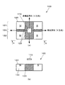
図2は、X方向位置検出装置100の拡大図である。図2(a)は、図1のII部拡大図であり、図2(b)は、図2(a)のb−b部矢視図である。なお、図2(a)において、水平方向が検出方向であるX方向を示し、垂直方向が非検出方向であるY方向を示している。
図2(a)に示すように、マグネット120は、その光軸I方向から見た平面形状を、各辺の方向をX方向、Y方向とそれぞれ略平行に配置された矩形に形成されている。また、図2(b)に示すように、マグネット120は、その磁気検出部110と対向する側の面部及びその反対側の面部が略平面に形成されている。このマグネット120の磁気検出部110と対向する面部は、X方向及びY方向とそれぞれ平行に配置され、これによって可動レンズ枠3の移動に追従してマグネット120が移動する際に、これと磁気検出部110との間隔が略一定となるようになっている。
FIG. 2 is an enlarged view of the X-direction
As shown in FIG. 2A, the
マグネット120は、X方向に離間して配置されたN極及びS極をそれぞれ有する1対の磁化領域121,122が、Y方向に離間して平行に配置されている。
各磁化領域121,122は、そのN極、S極の配列方向(磁化方向)が統一され、また、各磁化領域121,122は、それぞれN極とS極との間に挟まれて配置され、残留磁束密度が無視できる程度に低い無磁化領域123が形成されている。
In the
Each of the
また、マグネット120は、磁化領域121,122の間に設けられ、X方向に沿って帯状に延在し、かつ、その残留磁束密度が無視できる程度に低い無磁化領域124が形成されている。残留磁束密度とは、外部磁場をなくした場合にも磁性体の材料自体に残存する磁束密度をいう。
そして、磁気検出部110は、ブレ補正レンズ群2の光軸がレンズ鏡筒の光軸Iと一致した状態(センタリングされた状態)において、マグネット120に対して、Y方向においては無磁化領域124の中央部であり、かつ、X方向においては、無磁化領域123の中央部に相当する領域に対向するように配置されている。
なお、Y方向位置検出装置200は、その検出対象方向の違いに対応した装置の向きの違いを除くと、X方向位置検出装置100と同様の構成を備えている。
The
Then, the
The Y-direction
次に、上述した実施例1の効果を、以下説明する比較例と対比して説明する。
図3は、本発明の比較例における位置検出装置の構成を示す図である。なお、上述した実施例1のX方向位置検出装置100と同様の部分については同じ符号を付して説明を省略し、主に相違点について説明する。
比較例の位置検出装置500のマグネット520は、X方向に離間した1対のN極及びS極を備えており、これらのN極及びS極は、それぞれマグネット520のY方向における中央部に設けられている。そして、磁気検出部110は、ブレ補正レンズ群2の光軸がレンズ鏡筒の光軸Iと一致した状態において、マグネット520のN極とS極との中間部に対向するように配置されている。
Next, the effect of Example 1 mentioned above is demonstrated in contrast with the comparative example demonstrated below.
FIG. 3 is a diagram showing a configuration of a position detection device in a comparative example of the present invention. In addition, the same code | symbol is attached | subjected about the part similar to the X direction
The
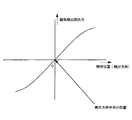
図4は、実施例1のX方向位置検出装置100におけるマグネット120のX方向(検出方向)の位置に対する磁気検出部110の出力例を示すグラフである。図4において、横軸はブレ補正レンズ群2がセンタリングされた状態を基準としたマグネット120の相対位置を示し、縦軸は磁気検出部110の出力を示している。
磁気検出部110の出力は、マグネット120がセンタリングされた状態のときに0となり、ここからの変位量が大きくなるにつれて増大し、その極性は変位の方向に応じて反転するから、この出力の低下に基づいて、磁気検出部110に対するマグネット120の変位を検出することができる。
また、このような傾向は、比較例の位置検出装置500においても共通するものである。
FIG. 4 is a graph illustrating an output example of the
The output of the
Such a tendency is common to the
一方、図5は、実施例1のX方向位置検出装置100、及び、比較例の位置検出装置500におけるマグネット120,520の磁気検出部110に対するY方向(非検出方向)の位置に対する磁気検出部110の出力例を示すグラフである。図5において、横軸はブレ補正レンズ群2がY方向についてセンタリングされ、X方向については(+)の出力のある状態を基準としたマグネット120、520の相対位置を示し、縦軸は磁気検出部110の出力を示している。なお、図中、実施例1を実線、比較例を破線で示している。
On the other hand, FIG. 5 shows a magnetic detection unit for the position in the Y direction (non-detection direction) relative to the
この場合、磁気検出部110の出力は、マグネット120,520が変位していないときに最大となり、ここからの変位量が大きくなるにつれて徐々に低下する。
このように、マグネット120,520が、磁気検出部110に対して非検出方向に変位した場合にも磁気検出部110の出力は変化するから、検出方向における位置検出に誤差が生じることになるが、実施例1は、比較例よりも非検出方向の変位に対する磁気検出部110の出力変化が少なくなっている。この点について、以下詳しく説明する。
In this case, the output of the
As described above, even when the
図6は、実施例1のX方向位置検出装置100、及び、比較例の位置検出装置500におけるマグネット120,520の磁気検出部110に対するY方向(非検出方向)の位置に応じた磁気検出部110における磁場強度のシミュレーション結果を示すグラフである。図6において、横軸はブレ補正レンズ群2がY方向についてセンタリングされた状態からのマグネット120、520の変位を示し、縦軸は規格化された磁場強度を示している。
このシミュレーションの前提条件は、以下の通りである。
(1)マグネット120,520のレンズ鏡筒の光軸I方向の厚さ:1.0mm
(2)マグネット120,520のX方向の長さ:1.65mm
(3)マグネット120,520のY方向の長さ:3.0mm
(4)X方向におけるN極とS極との間隔:1.0mm
(5)マグネット120,520と磁気検出部110との間隔:1.0mm
(6)Y方向における無磁化領域124の幅:0.2mm(実施例1のみ)
FIG. 6 illustrates a magnetic detection unit according to the position in the Y direction (non-detection direction) of the
The prerequisites for this simulation are as follows.
(1) Thickness of the lens barrel of the
(2) Length of
(3) Length of
(4) Distance between N pole and S pole in the X direction: 1.0 mm
(5) Distance between
(6) Width of the
図6に示すように、比較例は、ブレ補正用レンズ群2がY方向についてセンタリングされた状態から、マグネット520が非検出方向(Y方向)に0.6mm移動した場合は、磁気検出部110における磁場強度は約6%低下し、これによって位置検出に誤差が生じる。
これに対し、実施例1は、同様にマグネット120が移動した場合であっても、磁場強度の低下は約1.5%に抑えられるから、位置検出誤差を低減することができる。
As shown in FIG. 6, in the comparative example, when the
On the other hand, in the first embodiment, even when the
以上のように、実施例1によれば、磁化領域121,122の間に、検出方向(X方向)に沿って延在する無磁化領域124を配置しているから、非検出方向(Y方向)における磁場強度分布が平準化され、マグネット120が磁気検出部110に対してY方向に変位した場合における磁気検出部110の出力の変化を抑制することができる。これによって、位置検出装置の検出精度を確保することができる。
As described above, according to the first embodiment, since the
次に、本発明を適用した位置検出装置の実施例2について説明する。なお、以下説明する各実施例において、上述した実施例1と同様の部分については同じ符号を付して説明を省略し、主に相違点について説明する。 Next, a second embodiment of the position detection apparatus to which the present invention is applied will be described. Note that, in each embodiment described below, the same parts as those in the first embodiment described above are denoted by the same reference numerals, description thereof is omitted, and differences are mainly described.
図7は、実施例2のX方向位置検出装置300の構成を示す図である。図7(a)は、光軸I側から見た状態を示す図であり、図7(b)は、図7(a)のb−b部矢視図である。
X方向位置検出装置300のマグネット320は、実施例1のマグネット120における無磁化領域124に代えて、低磁化領域325を備えている。
低磁化領域325は、磁化領域121,122のN極間、S極間にそれぞれ挟まれて配置されたN極及びS極を有し、これらのN極、S極はその磁束密度が隣接する磁化領域121,122のN極、S極よりも小さくされている。
なお、X方向位置検出装置300は、ブレ補正レンズ群2がセンタリングされた状態において、磁気検出部110が低磁化領域325のX方向における中央部に対向するように配置される。
以上説明した実施例2によれば、上述した実施例1と同様の効果に加え、低磁化領域325の磁束密度の設定により、非検出方向における磁気強度分布の調整の自由度を向上できる。
FIG. 7 is a diagram illustrating a configuration of the X-direction
The
The
Note that the X-direction
According to the second embodiment described above, in addition to the same effects as the first embodiment described above, the degree of freedom in adjusting the magnetic intensity distribution in the non-detection direction can be improved by setting the magnetic flux density of the
図8は、実施例3のX方向位置検出装置400の構成を示す図である。図8(a)は、光軸I側から見た状態を示す図であり、図7(b)、図7(c)は、それぞれ図7(a)のb−b部矢視図、c−c部矢視図である。
X方向位置検出装置400のマグネット420は、X方向に離間して配置された1対のN極及びS極を備えている。これらのN極及びS極は、マグネット420のY方向における中央部に設けられている。また、マグネット420は、その磁気検出部110と対向する面部を凹ませて形成された溝部426が備えられている。
溝部426は、X方向に略直線状に延在し、Y方向においてはマグネット420の略中央部に配置されている。上述したN極及びS極は、それぞれこの溝部426の溝底面部に配置されている。溝部426の横断面は、例えば矩形に形成され、溝部426に長手方向にわたって略一定である。
なお、X方向位置検出装置400は、ブレ補正レンズ群2がセンタリングされた状態において、磁気検出部110がマグネット420のN極とS極との略中央部に対向するように配置される。
以上説明した実施例3によれば、上述した実施例1、実施例2と同様の効果に加え、着磁箇所を低減することができるから、製造が容易となる効果がある。
FIG. 8 is a diagram illustrating the configuration of the X-direction
The
The
Note that the X-direction
According to the third embodiment described above, in addition to the same effects as those of the first and second embodiments described above, the number of magnetized places can be reduced.
(変形例)
本発明は、以上説明した各実施例に限定されることなく、種々の変形や変更が可能であって、それらも本発明の均等の範囲内である。
(1)実施例1、実施例2は、複数の磁化領域の間に無磁化領域、低磁化領域のいずれか一方をそれぞれ配置しているが、これに限らず、無磁化領域と低磁化領域とを組み合わせて配置してもよい。また、無磁化領域、低磁化領域は、相対移動部のN極側、S極側の少なくとも一方に備えてもよい。
(2)実施例1、実施例2のような無磁化領域、低磁化領域を有する相対移動部は、その両側の磁化領域と一体に形成された磁性体を用いて、局所的に着磁の有無、程度を異ならせて形成してもよいが、別体に形成されそれぞれ着磁の有無、程度を異ならせた磁性体を組み合わせたり、無磁化領域に相当する部分を非磁性体によって形成してもよい。
(3)実施例3は、凹部として検出方向に延在する矩形断面の溝部を備えるが、凹部の形状はこれに限らず他の形状であってもよく、また、N極側、S極側の一方にのみ凹部を形成してもよい。
(4)実施例1、実施例2のように、無磁化領域、低磁化領域が形成された相対移動部に、実施例3のような溝部等の凹部を形成してもよい。
(Modification)
The present invention is not limited to the embodiments described above, and various modifications and changes can be made, and these are also within the equivalent scope of the present invention.
(1) In the first and second embodiments, either the non-magnetized region or the low-magnetized region is arranged between the plurality of magnetized regions. And may be arranged in combination. Further, the non-magnetized region and the low-magnetized region may be provided on at least one of the north pole side and the south pole side of the relative movement unit.
(2) A relative moving part having a non-magnetized region and a low-magnetized region as in Example 1 and Example 2 is locally magnetized using a magnetic body formed integrally with the magnetized regions on both sides thereof. It may be formed with different presence / absence and degree, but it can be formed by combining different magnetic bodies with different presence / absence and degree of magnetization, or by forming a part corresponding to non-magnetized region with non-magnetic material. May be.
(3) Although the third embodiment includes a groove having a rectangular cross section extending in the detection direction as a recess, the shape of the recess is not limited to this, and may be other shapes, and the N pole side and the S pole side You may form a recessed part only in one of these.
(4) Like Example 1 and Example 2, you may form recessed parts, such as a groove part like Example 3, in the relative movement part in which the non-magnetization area | region and the low magnetization area | region were formed.
1 ブレ補正装置
2 ブレ補正レンズ群
3 可動レンズ枠
4 X方向アクチュエータ
5 Y方向アクチュエータ
100 X方向位置検出装置
110 磁気検出部
120 マグネット
121,122 磁化領域
124 無磁化領域
DESCRIPTION OF
Claims (10)
前記相対移動部に対して前記第1方向及び前記第2方向に相対移動可能に前記相対移動部と対向して備えられ、前記N極及び前記S極の磁気を検出する磁気検出部とを含み、
前記相対移動部と前記磁気検出部との前記第1方向の相対位置を検出することを特徴とする位置検出装置。 A plurality of N poles are provided on one end side along the first direction and spaced apart in a second direction substantially orthogonal to the first direction, and on the other end side along the first direction in the second direction. A plurality of S poles spaced apart from each other, a relative moving part including a non-magnetized region extending in the first direction between the plurality of N poles and between the plurality of S poles;
A magnetic detection unit that is provided to face the relative movement unit so as to be capable of relative movement with respect to the relative movement unit in the first direction and the second direction, and that detects magnetism of the N pole and the S pole. ,
A position detection device that detects a relative position of the relative movement unit and the magnetic detection unit in the first direction.
前記相対移動部に対して前記第1方向及び前記第2方向に相対移動可能に前記相対移動部と対向して備えられ、前記N極及び前記S極の磁気を検出する磁気検出部とを含み、
前記相対移動部と前記磁気検出部との前記第1方向の相対位置を検出することを特徴とする位置検出装置。 A plurality of N poles are provided on one end side along the first direction and spaced apart in a second direction substantially orthogonal to the first direction, and on the other end side along the first direction in the second direction. A plurality of S poles spaced apart from each other, and a low magnetization region having a lower magnetic flux density than the plurality of N poles and the plurality of S poles between the plurality of N poles and between the plurality of S poles A relative movement part provided with,
A magnetic detection unit that is provided to face the relative movement unit so as to be capable of relative movement with respect to the relative movement unit in the first direction and the second direction, and that detects magnetism of the N pole and the S pole. ,
A position detection device that detects a relative position of the relative movement unit and the magnetic detection unit in the first direction.
前記相対移動部に対して前記第1方向及び前記第1方向と略直交する第2方向に相対移動可能に前記相対移動部と対向して備えられ、前記N極及び前記S極の磁気を検出する前記磁気検出部とを含み、
前記相対移動部と前記磁気検出部との前記第1方向の相対位置を検出することを特徴とする位置検出装置。 N pole is provided on one end side along the first direction, the S pole provided with the other end to the first direction, said the surface facing the magnetic detection portion of the N pole and the S pole A relative movement part provided with a recess parallel to the first direction;
It is provided to face the relative movement unit so as to be relatively movable in the first direction and a second direction substantially orthogonal to the first direction with respect to the relative movement unit, and detects the magnetism of the N pole and the S pole. and a said magnetic detection unit for,
A position detection device that detects a relative position of the relative movement unit and the magnetic detection unit in the first direction.
前記ブレ補正光学系を、その光軸に直交する平面に略沿って移動可能に支持するブレ補正光学系支持部と、
前記ブレ補正光学系を前記ブレ補正光学系支持部に対してその光軸と略直交する方向に駆動する駆動部と、
前記ブレ補正光学系及び前記ブレ補正光学系支持部の一方に固定された磁気検出部及び他方に固定された相対移動部を有する請求項1から請求項3までのいずれか1項に記載の位置検出装置と
を備えるブレ補正装置。 An image stabilization optical system;
A blur correction optical system support unit that supports the blur correction optical system movably along a plane orthogonal to the optical axis;
A drive unit that drives the blur correction optical system in a direction substantially orthogonal to the optical axis with respect to the blur correction optical system support;
The position according to any one of claims 1 to 3, further comprising: a magnetic detection unit fixed to one of the blur correction optical system and the blur correction optical system support unit, and a relative movement unit fixed to the other. A blur correction device comprising: a detection device.
前記第1方向と交差する第2方向に前記第1の磁気発生部と間隔を隔てて前記一端側に備えられ、前記第1の磁気発生部と同一極性の磁気を発生させる第2の磁気発生部と、
前記第1方向に沿った他端側に備えられ前記第1の磁気発生部とは異なる極性の磁気を発生させる第3の磁気発生部と、
前記第2方向に前記第3の磁気発生部と間隔を隔てて前記他端側に備えられ、前記第3の磁気発生部と同一極性の磁気を発生させる第4の磁気発生部と、
前記第1の磁気発生部と前記第2の磁気発生部との間に備えられ、前記第1の磁気発生部および前記第2の磁気発生部よりも低い磁気を発生する第1低磁気部と、
前記第3の磁気発生部と前記第4の磁気発生部との間に備えられ、前記第3の磁気発生部および前記第4の磁気発生部よりも低い磁気を発生する第2低磁気部と、
前記第1の磁気発生部、前記第2の磁気発生部、前記第3の磁気発生部および前記第4の磁気発生部と前記第1方向及び前記第2方向に相対移動可能であり、前記第1の磁気発生部、前記第2の磁気発生部、前記第3の磁気発生部および前記第4の磁気発生部から生じる前記磁気を検出する磁気検出部とを備え、
前記磁気検出部と、前記第1の磁気発生部、前記第2の磁気発生部、前記第3の磁気発生部および前記第4の磁気発生部との前記第1方向の相対位置を検出することを特徴とする位置検出装置。 A first magnetism generating section that is provided on one end side along the first direction and generates magnetism;
A second magnetic generation that is provided on the one end side in a second direction intersecting the first direction and spaced from the first magnetic generation unit, and generates magnetism having the same polarity as the first magnetic generation unit. And
A third magnetic generator that is provided on the other end side along the first direction and generates magnetism having a polarity different from that of the first magnetic generator;
A fourth magnetic generation unit provided on the other end side at a distance from the third magnetic generation unit in the second direction and generating magnetism having the same polarity as the third magnetic generation unit;
A first low magnetic part that is provided between the first magnetic generation part and the second magnetic generation part and that generates a lower magnetism than the first magnetic generation part and the second magnetic generation part; ,
A second low magnetic unit that is provided between the third magnetic generation unit and the fourth magnetic generation unit and generates a lower magnetism than the third magnetic generation unit and the fourth magnetic generation unit; ,
The first magnetic generation unit, the second magnetic generation unit, the third magnetic generation unit, and the fourth magnetic generation unit are relatively movable in the first direction and the second direction, and A magnetic detection unit that detects the magnetism generated from the first magnetic generation unit, the second magnetic generation unit, the third magnetic generation unit, and the fourth magnetic generation unit,
Detecting a relative position in the first direction between the magnetic detection unit, the first magnetic generation unit, the second magnetic generation unit, the third magnetic generation unit, and the fourth magnetic generation unit; A position detection device characterized by the above.
前記磁気検出部は、前記第1低磁気部及び前記第2低磁気部と対向して前記第1方向に沿って前記第1の磁気発生部、前記第2の磁気発生部、前記第3の磁気発生部および前記第4の磁気発生部と相対移動可能であり、
前記第1の磁気発生部、前記第2の磁気発生部、前記第3の磁気発生部および前記第4の磁気発生部は、前記第1方向に沿って前記磁気検出部と相対移動するとき、前記磁気検出部で検出される前記磁気が前記第1方向の相対移動量に対して所定の出力特性で変化するように配置されていることを特徴とする位置検出装置。 The position detection device according to claim 5,
The magnetic detection unit is configured to face the first low magnetic unit and the second low magnetic unit along the first direction along the first direction, the second magnetic generation unit, the third magnetic generation unit, and the third magnetic generation unit. It is movable relative to the magnetism generator and the fourth magnetism generator,
When the first magnetic generation unit, the second magnetic generation unit, the third magnetic generation unit, and the fourth magnetic generation unit move relative to the magnetic detection unit along the first direction, The position detection device is arranged so that the magnetism detected by the magnetism detection unit changes with a predetermined output characteristic with respect to the relative movement amount in the first direction.
前記第1低磁気部及び前記第2低磁気部は、前記第2方向に前記第1の磁気発生部、前記第2の磁気発生部、前記第3の磁気発生部および前記第4の磁気発生部と前記磁気検出部とが相対移動するとき、
前記磁気検出部で検出される前記磁気の位置検出誤差が抑制されるように配置されていることを特徴とする位置検出装置。 In the position detection device according to claim 5 or 6,
The first low magnetic part and the second low magnetic part are the first magnetic generation unit, the second magnetic generation unit, the third magnetic generation unit, and the fourth magnetic generation in the second direction. When the part and the magnetic detection part move relative to each other,
A position detection device, wherein the magnetic position detection error detected by the magnetic detection unit is arranged to be suppressed.
前記ブレ補正光学系を、その光軸に直交するとともに互いに直交するX軸とY軸とで構成されるXY平面に略沿って移動可能に支持するブレ補正光学系支持部と、
前記ブレ補正光学系を前記ブレ補正光学系支持部に対して前記XY平面に略沿って駆動する駆動部と、
請求項1から請求項3、請求項5から7に記載のいずれか1項に記載の第1及び第2の位置検出装置とを備え、
前記第1の位置検出装置は、前記第1方向がX軸に沿った方向であり、
前記第2の位置検出装置は、前記第1方向がY軸方向に沿った方向であるブレ補正装置。 An image stabilization optical system;
A blur correction optical system support that supports the blur correction optical system so as to be movable substantially along an XY plane composed of an X axis and a Y axis that are orthogonal to the optical axis and orthogonal to each other;
A drive unit that drives the blur correction optical system along the XY plane with respect to the blur correction optical system support;
The first and second position detection devices according to any one of claims 1 to 3 and claims 5 to 7 ,
The first position detecting device, up direction der that the first way direction is along the X axis,
It said second position detecting device, shake correcting device wherein the first way direction is the direction along the Y-axis direction.
Priority Applications (1)
| Application Number | Priority Date | Filing Date | Title |
|---|---|---|---|
| JP2005070775A JP4655701B2 (en) | 2005-03-14 | 2005-03-14 | Position detection device, blur correction device, and lens barrel |
Applications Claiming Priority (1)
| Application Number | Priority Date | Filing Date | Title |
|---|---|---|---|
| JP2005070775A JP4655701B2 (en) | 2005-03-14 | 2005-03-14 | Position detection device, blur correction device, and lens barrel |
Publications (3)
| Publication Number | Publication Date |
|---|---|
| JP2006250857A JP2006250857A (en) | 2006-09-21 |
| JP2006250857A5 JP2006250857A5 (en) | 2008-05-08 |
| JP4655701B2 true JP4655701B2 (en) | 2011-03-23 |
Family
ID=37091519
Family Applications (1)
| Application Number | Title | Priority Date | Filing Date |
|---|---|---|---|
| JP2005070775A Expired - Fee Related JP4655701B2 (en) | 2005-03-14 | 2005-03-14 | Position detection device, blur correction device, and lens barrel |
Country Status (1)
| Country | Link |
|---|---|
| JP (1) | JP4655701B2 (en) |
Families Citing this family (8)
| Publication number | Priority date | Publication date | Assignee | Title |
|---|---|---|---|---|
| JP5040658B2 (en) | 2005-10-25 | 2012-10-03 | 株式会社ニコン | Position detection apparatus, two-dimensional position measurement apparatus, optical instrument, and position detection method |
| JP4859792B2 (en) * | 2007-08-30 | 2012-01-25 | トッパン・フォームズ株式会社 | Mark detection system |
| JP4823174B2 (en) * | 2007-08-30 | 2011-11-24 | トッパン・フォームズ株式会社 | Form |
| JP6006534B2 (en) * | 2012-05-29 | 2016-10-12 | 旭化成エレクトロニクス株式会社 | Position detection device |
| JP6018417B2 (en) * | 2012-05-29 | 2016-11-02 | 旭化成エレクトロニクス株式会社 | Position detection device |
| KR101479637B1 (en) * | 2014-03-12 | 2015-01-07 | 삼성전기주식회사 | Camera Module |
| KR102458711B1 (en) * | 2015-08-26 | 2022-10-25 | 엘지이노텍 주식회사 | Lens moving unit and camera module including the same |
| JP6986002B2 (en) * | 2018-11-26 | 2021-12-22 | Tdk株式会社 | Magnetic sensor device |
Citations (7)
| Publication number | Priority date | Publication date | Assignee | Title |
|---|---|---|---|---|
| JPS54164155A (en) * | 1978-06-16 | 1979-12-27 | Suwa Seikosha Kk | Positional detector |
| JPH0898488A (en) * | 1994-09-22 | 1996-04-12 | Nippon Seiko Kk | Three-phase brushless motor |
| JPH08136207A (en) * | 1994-11-08 | 1996-05-31 | Canon Inc | Position detector |
| JPH10132506A (en) * | 1996-10-30 | 1998-05-22 | Denso Corp | Rotation angle sensor |
| JP2002310722A (en) * | 2001-04-19 | 2002-10-23 | Aisin Seiki Co Ltd | Angle sensor |
| JP2003214897A (en) * | 2001-11-19 | 2003-07-30 | Nippon Soken Inc | Displacement amount sensor |
| JP2004245765A (en) * | 2003-02-17 | 2004-09-02 | Nikon Corp | Position detection device and blur correction device |
-
2005
- 2005-03-14 JP JP2005070775A patent/JP4655701B2/en not_active Expired - Fee Related
Patent Citations (7)
| Publication number | Priority date | Publication date | Assignee | Title |
|---|---|---|---|---|
| JPS54164155A (en) * | 1978-06-16 | 1979-12-27 | Suwa Seikosha Kk | Positional detector |
| JPH0898488A (en) * | 1994-09-22 | 1996-04-12 | Nippon Seiko Kk | Three-phase brushless motor |
| JPH08136207A (en) * | 1994-11-08 | 1996-05-31 | Canon Inc | Position detector |
| JPH10132506A (en) * | 1996-10-30 | 1998-05-22 | Denso Corp | Rotation angle sensor |
| JP2002310722A (en) * | 2001-04-19 | 2002-10-23 | Aisin Seiki Co Ltd | Angle sensor |
| JP2003214897A (en) * | 2001-11-19 | 2003-07-30 | Nippon Soken Inc | Displacement amount sensor |
| JP2004245765A (en) * | 2003-02-17 | 2004-09-02 | Nikon Corp | Position detection device and blur correction device |
Also Published As
| Publication number | Publication date |
|---|---|
| JP2006250857A (en) | 2006-09-21 |
Similar Documents
| Publication | Publication Date | Title |
|---|---|---|
| JP5040658B2 (en) | Position detection apparatus, two-dimensional position measurement apparatus, optical instrument, and position detection method | |
| JP4655701B2 (en) | Position detection device, blur correction device, and lens barrel | |
| KR101960493B1 (en) | Optical adjusting apparatus | |
| US8159746B2 (en) | Optical apparatus with image stabilizing and movable lenses and actuators for shifting and/or moving the lenses | |
| JP4874591B2 (en) | Stage device and camera shake correction device using the stage device | |
| JP4899712B2 (en) | Lens barrel | |
| JP3952207B2 (en) | Actuator and lens unit and camera provided with the same | |
| JP5347193B2 (en) | Anti-vibration actuator, lens unit and camera equipped with the same | |
| US8908272B2 (en) | Image blur correcting device and image pickup device | |
| JP2012078450A (en) | Shake correction device, lens barrel, and optical instrument | |
| JP2005284169A (en) | Driving device and optical equipment | |
| US9030741B2 (en) | Image stabilizing apparatus, lens barrel, and optical apparatus | |
| JP2008233525A (en) | Actuator, lens unit equipped therewith and camera | |
| JP6672656B2 (en) | Position detecting device and optical device | |
| KR20140027418A (en) | Imaging device | |
| JP2006250857A5 (en) | ||
| JP2019095540A (en) | Tremor correction device | |
| CN107561820B (en) | Actuator, and lens unit and camera provided with same | |
| JP4742558B2 (en) | Blur correction imaging apparatus and camera | |
| JP2009230025A (en) | Coil drive unit, blur correction mechanism and imaging apparatus | |
| JP2016144257A (en) | Magnet device | |
| JP6065563B2 (en) | Position detecting device and photographing device | |
| JP5365088B2 (en) | Image shake correction apparatus and optical apparatus using the same | |
| JP2020194049A (en) | Imaging device | |
| JP2006284415A (en) | Position detection system and camera |
Legal Events
| Date | Code | Title | Description |
|---|---|---|---|
| A621 | Written request for application examination |
Free format text: JAPANESE INTERMEDIATE CODE: A621 Effective date: 20080307 |
|
| A521 | Written amendment |
Free format text: JAPANESE INTERMEDIATE CODE: A523 Effective date: 20080326 |
|
| A977 | Report on retrieval |
Free format text: JAPANESE INTERMEDIATE CODE: A971007 Effective date: 20100408 |
|
| A131 | Notification of reasons for refusal |
Free format text: JAPANESE INTERMEDIATE CODE: A131 Effective date: 20100413 |
|
| A521 | Written amendment |
Free format text: JAPANESE INTERMEDIATE CODE: A523 Effective date: 20100614 |
|
| A131 | Notification of reasons for refusal |
Free format text: JAPANESE INTERMEDIATE CODE: A131 Effective date: 20100817 |
|
| A521 | Written amendment |
Free format text: JAPANESE INTERMEDIATE CODE: A523 Effective date: 20101018 |
|
| TRDD | Decision of grant or rejection written | ||
| A01 | Written decision to grant a patent or to grant a registration (utility model) |
Free format text: JAPANESE INTERMEDIATE CODE: A01 Effective date: 20101130 |
|
| A01 | Written decision to grant a patent or to grant a registration (utility model) |
Free format text: JAPANESE INTERMEDIATE CODE: A01 |
|
| A61 | First payment of annual fees (during grant procedure) |
Free format text: JAPANESE INTERMEDIATE CODE: A61 Effective date: 20101213 |
|
| FPAY | Renewal fee payment (event date is renewal date of database) |
Free format text: PAYMENT UNTIL: 20140107 Year of fee payment: 3 |
|
| R150 | Certificate of patent or registration of utility model |
Ref document number: 4655701 Country of ref document: JP Free format text: JAPANESE INTERMEDIATE CODE: R150 Free format text: JAPANESE INTERMEDIATE CODE: R150 |
|
| FPAY | Renewal fee payment (event date is renewal date of database) |
Free format text: PAYMENT UNTIL: 20140107 Year of fee payment: 3 |
|
| R250 | Receipt of annual fees |
Free format text: JAPANESE INTERMEDIATE CODE: R250 |
|
| R250 | Receipt of annual fees |
Free format text: JAPANESE INTERMEDIATE CODE: R250 |
|
| R250 | Receipt of annual fees |
Free format text: JAPANESE INTERMEDIATE CODE: R250 |
|
| R250 | Receipt of annual fees |
Free format text: JAPANESE INTERMEDIATE CODE: R250 |
|
| R250 | Receipt of annual fees |
Free format text: JAPANESE INTERMEDIATE CODE: R250 |
|
| R250 | Receipt of annual fees |
Free format text: JAPANESE INTERMEDIATE CODE: R250 |
|
| R250 | Receipt of annual fees |
Free format text: JAPANESE INTERMEDIATE CODE: R250 |
|
| LAPS | Cancellation because of no payment of annual fees |