JP4654477B2 - Cylindrical sealed lead-acid battery - Google Patents
Cylindrical sealed lead-acid battery Download PDFInfo
- Publication number
- JP4654477B2 JP4654477B2 JP37286099A JP37286099A JP4654477B2 JP 4654477 B2 JP4654477 B2 JP 4654477B2 JP 37286099 A JP37286099 A JP 37286099A JP 37286099 A JP37286099 A JP 37286099A JP 4654477 B2 JP4654477 B2 JP 4654477B2
- Authority
- JP
- Japan
- Prior art keywords
- length
- electrode plate
- winding
- grid
- ratio
- Prior art date
- Legal status (The legal status is an assumption and is not a legal conclusion. Google has not performed a legal analysis and makes no representation as to the accuracy of the status listed.)
- Expired - Fee Related
Links
Images


Classifications
-
- Y—GENERAL TAGGING OF NEW TECHNOLOGICAL DEVELOPMENTS; GENERAL TAGGING OF CROSS-SECTIONAL TECHNOLOGIES SPANNING OVER SEVERAL SECTIONS OF THE IPC; TECHNICAL SUBJECTS COVERED BY FORMER USPC CROSS-REFERENCE ART COLLECTIONS [XRACs] AND DIGESTS
- Y02—TECHNOLOGIES OR APPLICATIONS FOR MITIGATION OR ADAPTATION AGAINST CLIMATE CHANGE
- Y02E—REDUCTION OF GREENHOUSE GAS [GHG] EMISSIONS, RELATED TO ENERGY GENERATION, TRANSMISSION OR DISTRIBUTION
- Y02E60/00—Enabling technologies; Technologies with a potential or indirect contribution to GHG emissions mitigation
- Y02E60/10—Energy storage using batteries
-
- Y—GENERAL TAGGING OF NEW TECHNOLOGICAL DEVELOPMENTS; GENERAL TAGGING OF CROSS-SECTIONAL TECHNOLOGIES SPANNING OVER SEVERAL SECTIONS OF THE IPC; TECHNICAL SUBJECTS COVERED BY FORMER USPC CROSS-REFERENCE ART COLLECTIONS [XRACs] AND DIGESTS
- Y02—TECHNOLOGIES OR APPLICATIONS FOR MITIGATION OR ADAPTATION AGAINST CLIMATE CHANGE
- Y02P—CLIMATE CHANGE MITIGATION TECHNOLOGIES IN THE PRODUCTION OR PROCESSING OF GOODS
- Y02P70/00—Climate change mitigation technologies in the production process for final industrial or consumer products
- Y02P70/50—Manufacturing or production processes characterised by the final manufactured product
Landscapes
- Cell Electrode Carriers And Collectors (AREA)
- Secondary Cells (AREA)
Description
【0001】
【発明の属する技術分野】
本発明は、円筒形密閉鉛蓄電池に関するものである。
【0002】
【従来の技術】
従来より、円筒形の密閉蓄電池に用いられるため、鋳造加工または圧延と打抜き加工により製作される格子体は、図4に示すように枠骨1と、直交配列された縦桟2と横桟3、および集電のため枠骨に配設された格子耳とで構成され、これにペースト状の活物質を充填して極板とされてきた。
【0003】
しかしながら、一般には、縦桟の長さ(隣合う横桟間の距離)aと横桟の長さ(隣合う縦桟間の距離)bとの比a/bを1以下としたもの、すなわち、格子体の上部枠骨1aに沿った方向に長い桝目形状を成す格子体が使用されており、しかも、極板の巻始部から巻終部までの全長にわたって寸法a、bに変化なく、同じ形状の桝目が連なったものが使用されている。
【0004】
【発明が解決しようとする課題】
上述の上部枠骨に沿った方向に長い桝目形状を持つ格子体を用いた場合、格子体にペースト状活物質を充填した正極板と負極板とをセパレータを介して巻回し、電極体を形成する際に、巻回時の格子体の変形により活物質の剥離あるいは脱落が発生する。そして、極板の活物質層に亀裂が入ることにより電気的接続が十分保たれない部分が生じることから、蓄電池としての容量密度や高率放電特性などの電池特性の低下を招くだけでなく、蓄電池の使用中に機械的振動等を受けて活物質が極板から脱離した場合には、容量低下を引き起こすことになり、充放電サイクル特性が低下する。
さらに、脱落した活物質が極板とセパレータの間に噛み込んで、セパレータを突き破るようなこともあり、最悪の場合には、内部短絡の発生から発熱・発火につながることもあり得る。
【0005】
【課題を解決するための手段】
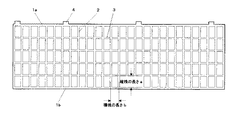
本発明の円筒形密閉鉛蓄電池では、正極板または負極板の少なくともいずれか一方の格子体において、図1に示す実施例に見られるように、格子体の桝目における縦桟の長さが横桟の長さより大きく、縦長な形状を有することを特徴としている。
【0006】
なお、ここで、縦桟、横桟の長さとは、それぞれの隣接する横桟同士、縦桟同士の桟中心相互間の距離として定義されるものとする。
【0007】
巻始部では、巻回半径が短いため、巻回時に活物質の剥離や脱落を起こしやすくなる傾向にあるが、このように縦桟間の間隔を狭くすることにより、この間に充填された活物質が縦桟により両側から挟持されるため、活物質の剥離や脱落の発生を確実に防止することができる。
【0008】
さらに、本発明の前記格子体桝目形状においては、縦桟と横桟の長さの比を巻始部側で大きく、巻終部側で小さくすることすることを特徴とする。この実施例を図2に示す。図2において巻始部は左側に、巻終部は右側に位置するよう示しているが、縦桟の長さを巻始部でも巻終部でも同じとした場合、横桟の長さを巻始部側で短く、巻終部側で長く設定することになる。
【0009】
この第二の特徴を持たせることにより、前掲の実施例の場合と同様、巻始部における活物質の剥離や脱落を確実に防止することができるとともに、曲げ半径が大きい巻終部側では、格子体重量を相対的に軽減できることになる。巻終部側では、極板中を流れる電流密度を考慮して、縦桟の配列間隔および縦桟の幅あるいは太さを適正寸法に設定すればよく、このことにより、蓄電池の重量当たりの容量密度(Ah/kg)、エネルギー密度(Wh/kg)を向上させることが可能となる。
【0010】
さらに、図3は、本発明の特徴を活かした実施例に当たるが、巻終部側で縦桟の長さを長くしながら、横桟の長さとの比を、巻始部側での比よりも小さくしたものであり、電池性能に余り寄与しない横桟の重量を減らして、充填できる活物質の重量を増やし、蓄電池としての容量密度、単位重量当たりのエネルギー密度を更に向上させようとしたものである。
格子体を構成する縦桟および横桟の相互隣接距離や断面積は、蓄電池のエネルギー密度や高率放電特性を始めとする種々の電池特性、ならびに強度や耐震性等の信頼性にも大きな影響を及ぼす因子である。上述したように、縦桟の隣接距離を相対的に短く設定した本発明の格子体を、円筒形密閉蓄電池の正極板または負極板の少なくともいずれか一方に用いて構成することによって、電池性能と信頼性の向上を実現させることが可能である。
また、極板からの活物質脱落を防止することは、先にも記したように内部短絡の発生を防止した安全性の高い蓄電池を提供するだけでなく、容量密度、サイクル寿命等の性能バラツキを無い信頼性の高い蓄電池を提供し、かつ製造工程での歩留り向上、コスト低減にも寄与するものである。
【0011】
巻始部側における縦桟と横桟の長さの比は、基本的には巻回時の活物質脱落や寸法精度の維持等の作業性への配慮から決まるものであり、通常2.0〜5.0の範囲に設定され、好ましくは2.5〜3.0の範囲に設定される。他方、巻終部側では、極板の巻回軸方向への変形を抑制でき、適正な電流密度が確保できる範囲内であれば、縦桟の配置密度を低くしても良く、そのことによって格子体全体の重量を減らし、電池の容量密度向上に繋がることにもなる。そのような観点から、巻終部側における縦桟と横桟の長さの比は、通常1.0〜2.0の範囲に設定され、好ましくは1.2〜1.5の範囲に設定される。
【0012】
以上に述べたように、縦桟と横桟の長さの比は、巻始部では2.5〜3.0、巻終部では1.2〜1.5の範囲とすることが好ましく、さらに、この巻始部と巻終部の間にあっては、縦桟と横桟の長さの比をいくつかの段階に分けて漸次変化させることが望ましい。
縦桟と横桟の長さの比を1.0より大きくするということは、格子体中に占める縦桟の重量比率を増やすことになる。巻回された渦巻電極体の場合、極板の膨張・収縮に伴う電極体の変形は、極板の厚さ方向ならびに円周方向で小さく、巻回軸方向で比較的大きい。縦桟の配列密度が大きく、縦桟の占める重量比率が大きいと、この巻回軸方向の変形を抑制する方向に作用する。したがって、本願発明における縦桟と横桟の長さの比を1.0より大きくした格子体の場合、渦巻電極体の巻回軸方向への変形を抑え、活物質の脱落や短絡の発生を防止し、さらに電池の長寿命化に寄与することになる。
【0013】
【発明の実施の形態】
以下、いくつかの実施例をもとに本発明の実施の形態とその効果を説明する。
【0014】
(実施例)
本発明の実施形態として、図1および図2に示す桝目形状を有する格子体を正極板ならびに負極板に用いて作製した公称容量5Ahの円筒形密閉鉛蓄電池を取り上げた。
【0015】
実施例1の格子体(図1に示す実施形態に対応)として、厚さ0.6mm、幅80mm×長さ500mmの圧延鉛合金シートに、巻始部から巻終部まで縦桟の長さ10mm一定で、横桟の長さをそれぞれ3mm、5mm、8mmとして打抜いた3種類の格子体を作製し、正極板および負極板に使用した。
【0016】
正極板は、酸化度70%(金属鉛30%、一酸化鉛70%)の鉛粉と希硫酸とを混練して得た活物質ペーストを、前記格子体の両面に塗布、充填することにより作製した。また、負極板は、酸化度70%(金属鉛30%、一酸化鉛70%)の鉛粉に若干の炭素粉末とリグニンとを添加し、希硫酸を加えて混練して得た活物質ペーストを、前記格子体の両面に塗布、充填することにより作製した。正極板、負極板のそれぞれの理論容量を12Ah、16Ahとして活物質充填量を設定していたが、実際には格子開口部分の容積に差異があり、また、充填した活物質が極板のハンドリング時や巻回時に脱落したこともあり、極板により活物質充填量に多少の増減が生じた。
【0017】
次に、これらの正極板と負極板を、ガラスマットセパレータを介して巻回して渦巻状電極体を構成した。そして、この電極体の格子耳部をストラップで接続した後、樹脂製の円筒形容器に入れて封口し、さらに注液口から電解液(所定比重の希硫酸水溶液)を減圧注入して、円筒形密閉鉛蓄電池を得た。なお、この電池に0.25CA定電流×40時間の条件で電槽化成を施した後、下記の容量確認試験と充放電サイクル試験に供した。
【0018】
実施例2の格子体(図2に示す実施形態に対応)としては、厚さ0.6mm、幅80mm×長さ500mmの圧延鉛合金シートに、巻始部からの距離が0〜150mmの間は縦桟の長さ10mmで、横桟の長さを3mmとし、巻始部からの距離が150〜300mmの間は横桟の長さを5mm、巻始部からの距離が300〜500mm(巻終部)の間は横桟の長さを8mmと変化させて打抜き、正極板および負極板に使用した。試験電池の作製方法は、前記実施例1の試験電池の場合と同じである。
【0019】
一方、比較例として、厚さ0.6mm、幅80mm×長さ500mmの圧延鉛合金シートに、巻始部から巻終部まで、縦桟の長さ5mm、横桟の長さ7mmで打抜いたものを使用した。試験電池の作製方法は、前記実施例1の試験電池の場合と同じである。
【0020】
これらの円筒形鉛蓄電池に対して、0.2CAの放電電流での容量確認試験を実施した。このときの初期容量確認試験の結果を表1に示す。なお、表中の容量密度は、試験電池の初期容量を電極体重量で除した値であり、ここでの電極体重量としては、正極、負極、セパレータの重量およびこれらに含まれる電解液の重量の合計重量を用いた。
【0021】

実施例1の3種類の試験電池の中で、縦桟と横桟の長さの比が小さくなるに伴い、試験電池の初期容量および容量密度が大きくなっており、これは、実際に充填できた活物質量に依存したものと思われる。これに対して、比較例の試験電池では、実施例1の試験電池に比べ、初期容量、容量密度とも少し低い方に位置している。これは、製造工程において活物質が脱落等により損なわれたためと思われる。
【0023】
続いて、これらの円筒形鉛蓄電池を用いて充放電サイクル試験を実施した。充放電条件は、1CA定電流+2.45V定電圧充電(総充電時間1.5時間)と1CA放電(終止電圧1.7V)との繰り返しとした。充放電サイクル経過に伴う容量維持特性を図5に示すとともに、その結果を表2にまとめる。
【0024】
本発明の実施例1および2の試験電池は、いずれも充放電の繰返しによる容量低下が少なく、高い容量維持率を示している。これは、実施例の格子体においては縦桟の配列密度が高く、充放電の繰返しに伴う極板の変形が抑制されたことに起因しているものと思われる。比較例の試験電池では、電池製作時に極板の活物質層に亀裂が生じ、電気的接続の十分に保たれていない部分が存在し、そのような活物質が充放電の繰返しに伴う極板の変形により徐々に脱落していったことが容量維持率の低下を助長したものと思われる。単に容量維持率の点からすれば、実施例における縦桟と横桟の長さの比の大きいものの方が良いが、初期容量や容量密度にも重点を置くと、縦桟と横桟の長さの比を巻始部と巻終部で変化させたもの(実施例2)が最も優れていると言える。
【0026】
なお、上記実施例は、正極板と負極板の両方に、縦桟の長さの方が長い格子体を用いたが、性能向上の理由からして、当然ながら、正極板または負極板のいずれかに一方に前記の格子体を用いても同様の効果が得られる。
【0027】
また、上記実施例では円筒形鉛蓄電池における適用例を示したが、縦桟と横桟とが直交配列された桝目構造を持つ格子体を用いる他の蓄電池においても、同じく、本発明は同様の効果を発揮し得るものである。
【0028】
【発明の効果】
以上に示したごとく、格子体の各桝目における縦桟の長さaと横桟の長さbの比a/bが1より大きいことを特徴とする格子体を、円筒形密閉鉛蓄電池の正極板または負極板の少なくともいずれか一方に用いることにより、活物質の剥離、脱落を防止し、容量密度、サイクル特性に優れた円筒形密閉鉛蓄電池を提供することができる。
【図面の簡単な説明】
【図1】本願発明に関わる格子体形状図(縦桟長さaと横桟長さbとの比a/bが1より大きい桝目形状が巻始部から巻終部まで連なる実施例)
【図2】本願発明に関わる格子体形状図(巻終部側における縦桟長さa’と横桟長さb’との比a’/b’を、巻始部側におけるa/bよりも小さく設定したした実施例)
【図3】本願発明に関わる格子体形状図(巻終部側で縦桟長さa’を大きく設定し、かつ縦桟間の距離bとの比a/bを巻始部よりも小さく設定した実施例)
【図4】従来の格子体形状図
【符号の説明】
1 枠 骨、
1a 上部横骨、
1b 下部横骨、
2 縦桟、
3 横桟、
4 格子耳、
5 活物質[0001]
BACKGROUND OF THE INVENTION
The present invention relates to a cylindrical sealed lead-acid battery.
[0002]
[Prior art]
Conventionally, since it is used for a cylindrical sealed storage battery, a lattice body manufactured by casting or rolling and punching is a frame 1, a
[0003]
However, in general, the ratio a / b between the length of the vertical beam (distance between adjacent horizontal beams) a and the length of the horizontal beam (distance between adjacent vertical beams) b is 1 or less, that is, In addition, a grid body having a long grid shape in the direction along the upper frame bone 1a of the grid body is used, and the dimensions a and b do not change over the entire length from the winding start part to the winding end part of the electrode plate, A series of cells with the same shape is used.
[0004]
[Problems to be solved by the invention]
When a grid body having a long grid shape in the direction along the upper frame bone is used, a positive electrode plate filled with a paste-like active material and a negative electrode plate are wound through a separator to form an electrode body In this case, the active material is peeled off or dropped due to deformation of the lattice during winding. And, since the portion where the electrical connection is not sufficiently maintained due to cracks in the active material layer of the electrode plate, not only causes a decrease in battery characteristics such as capacity density and high rate discharge characteristics as a storage battery, When the active material is detached from the electrode plate due to mechanical vibration or the like during use of the storage battery, the capacity is reduced and charge / discharge cycle characteristics are deteriorated.
Further, the fallen active material may be caught between the electrode plate and the separator and break through the separator. In the worst case, the internal short circuit may lead to heat generation and ignition.
[0005]
[Means for Solving the Problems]
In the cylindrical sealed lead-acid battery according to the present invention, as shown in the embodiment shown in FIG. 1, in the grid body of at least one of the positive electrode plate and the negative electrode plate, the length of the vertical beam at the grid is equal to the horizontal beam. It is characterized by having a vertically long shape that is larger than the length of.
[0006]
Here, the length of the vertical beam and the horizontal beam is defined as the distance between the adjacent horizontal beams and the center of the vertical beams.
[0007]
Since the winding radius is short at the winding start portion, the active material tends to be peeled off or dropped off during winding. Since the material is sandwiched from both sides by the vertical beam, the active material can be reliably prevented from peeling off or falling off.
[0008]
Further, in the grid body grid shape of the present invention, the ratio of the length of the vertical beam to the horizontal beam is increased on the winding start side and decreased on the winding end side. This embodiment is shown in FIG. In FIG. 2, the winding start portion is shown on the left side and the winding end portion is on the right side. However, if the length of the vertical beam is the same at the winding start portion and the winding end portion, the length of the horizontal beam is wound. The length is set short on the start side and long on the winding end side.
[0009]
By giving this second feature, it is possible to reliably prevent the active material from peeling off and falling off at the winding start portion as in the case of the above-described example, and at the winding end portion where the bending radius is large, The grid body weight can be relatively reduced. At the end of the winding, considering the current density flowing in the electrode plate, the arrangement interval of the vertical bars and the width or thickness of the vertical bars may be set to appropriate dimensions. The density (Ah / kg) and energy density (Wh / kg) can be improved.
[0010]
Furthermore, FIG. 3 corresponds to an embodiment utilizing the features of the present invention. While the length of the vertical beam is increased on the winding end portion side, the ratio of the length of the horizontal beam is compared with the ratio on the winding start side. In order to further improve the capacity density as a storage battery and the energy density per unit weight, the weight of the horizontal beam that does not contribute much to the battery performance is reduced and the weight of the active material that can be filled is increased. It is.
The mutual adjacent distance and cross-sectional area of the vertical and horizontal beams that make up the grid body have a great influence on various battery characteristics such as energy density and high-rate discharge characteristics of storage batteries, and reliability such as strength and earthquake resistance. Is a factor that affects As described above, by using the grid body of the present invention in which the adjacent distance between the vertical rails is set to be relatively short for at least one of the positive electrode plate and the negative electrode plate of the cylindrical sealed storage battery, battery performance and It is possible to improve the reliability.
In addition, as described above, preventing the active material from falling off the electrode plate not only provides a highly safe storage battery that prevents the occurrence of an internal short circuit, but also varies in performance such as capacity density and cycle life. In addition to providing a highly reliable storage battery, it also contributes to improvement in yield and cost reduction in the manufacturing process.
[0011]
The ratio of the length of the vertical beam to the horizontal beam on the winding start side is basically determined by considerations for workability such as dropping of the active material and maintenance of dimensional accuracy during winding. It is set in the range of -5.0, preferably in the range of 2.5-3.0. On the other hand, on the winding end side, deformation in the direction of the winding axis of the electrode plate can be suppressed, and the arrangement density of the vertical rails may be lowered as long as the appropriate current density can be secured. The weight of the whole grid | lattice body will be reduced and it will also lead to the capacity density improvement of a battery. From such a viewpoint, the ratio of the length of the vertical beam to the horizontal beam at the end of the winding is usually set in the range of 1.0 to 2.0, preferably in the range of 1.2 to 1.5. Is done.
[0012]
As described above, the ratio of the length of the vertical beam to the horizontal beam is preferably in the range of 2.5 to 3.0 at the start of winding and 1.2 to 1.5 at the end of winding, Further, it is desirable that the ratio between the length of the vertical beam and the horizontal beam is gradually changed in several stages between the winding start part and the winding end part.
Increasing the ratio of the length of the vertical beam to the horizontal beam exceeds 1.0 increases the weight ratio of the vertical beam in the lattice. In the case of a wound spiral electrode body, the deformation of the electrode body accompanying the expansion and contraction of the electrode plate is small in the thickness direction and the circumferential direction of the electrode plate, and relatively large in the winding axis direction. When the arrangement density of the vertical bars is large and the weight ratio of the vertical bars is large, it acts in a direction to suppress the deformation in the winding axis direction. Therefore, in the case of the grid body in which the ratio of the length of the vertical beam to the horizontal beam in the present invention is larger than 1.0, the deformation of the spiral electrode body in the direction of the winding axis is suppressed, and the active material is prevented from dropping or short-circuiting. This contributes to a longer battery life.
[0013]
DETAILED DESCRIPTION OF THE INVENTION
Hereinafter, embodiments of the present invention and effects thereof will be described based on some examples.
[0014]
(Example)
As an embodiment of the present invention, a cylindrical sealed lead-acid battery having a nominal capacity of 5 Ah manufactured using the grid body having the grid shape shown in FIGS. 1 and 2 as a positive electrode plate and a negative electrode plate was taken up.
[0015]
As the grid body of Example 1 (corresponding to the embodiment shown in FIG. 1), the length of the vertical beam from the winding start portion to the winding end portion on a rolled lead alloy sheet having a thickness of 0.6 mm, a width of 80 mm × a length of 500 mm. Three types of grids were formed by punching with a horizontal rail length of 3 mm, 5 mm, and 8 mm, respectively, with a constant 10 mm, and used for the positive electrode plate and the negative electrode plate.
[0016]
The positive electrode plate is formed by applying and filling an active material paste obtained by kneading lead powder having a degree of oxidation of 70% (metal lead 30%, lead monoxide 70%) and dilute sulfuric acid on both sides of the lattice body. Produced. The negative electrode plate is an active material paste obtained by adding some carbon powder and lignin to lead powder with an oxidation degree of 70% (metal lead 30%, lead monoxide 70%), adding dilute sulfuric acid and kneading. Was prepared by coating and filling both sides of the lattice. The active material filling amount was set by setting the theoretical capacity of the positive electrode plate and the negative electrode plate to 12 Ah and 16 Ah, respectively. However, there is actually a difference in the volume of the lattice opening, and the filled active material is handled by the electrode plate. Sometimes it dropped out at the time of winding or winding, and the active material filling amount slightly increased or decreased due to the electrode plate.
[0017]
Next, the positive electrode plate and the negative electrode plate were wound through a glass mat separator to form a spiral electrode body. Then, after connecting the lattice ears of this electrode body with a strap, it is sealed in a resin-made cylindrical container, and an electrolytic solution (diluted sulfuric acid aqueous solution having a specific gravity) is injected under reduced pressure from a liquid injection port. A sealed lead-acid battery was obtained. The battery was subjected to battery formation under the condition of 0.25 CA constant current × 40 hours, and then subjected to the following capacity confirmation test and charge / discharge cycle test.
[0018]
As the grid body of Example 2 (corresponding to the embodiment shown in FIG. 2), the distance from the winding start portion is 0 to 150 mm on a rolled lead alloy sheet having a thickness of 0.6 mm, a width of 80 mm and a length of 500 mm. The length of the vertical beam is 10 mm, the length of the horizontal beam is 3 mm, the length of the horizontal beam is 5 mm while the distance from the winding start part is 150 to 300 mm, and the distance from the winding start part is 300 to 500 mm ( During the end of winding, the length of the cross rail was changed to 8 mm and punched out and used for the positive electrode plate and the negative electrode plate. The method for producing the test battery is the same as that for the test battery of Example 1.
[0019]
On the other hand, as a comparative example, a rolled lead alloy sheet having a thickness of 0.6 mm, a width of 80 mm and a length of 500 mm is punched from the winding start portion to the winding end portion with a vertical beam length of 5 mm and a horizontal beam length of 7 mm. Used. The method for producing the test battery is the same as that for the test battery of Example 1.
[0020]
A capacity confirmation test with a discharge current of 0.2 CA was performed on these cylindrical lead-acid batteries. The results of the initial capacity confirmation test at this time are shown in Table 1. The capacity density in the table is a value obtained by dividing the initial capacity of the test battery by the weight of the electrode body, and the weight of the electrode body here includes the weight of the positive electrode, the negative electrode, the separator, and the weight of the electrolyte contained therein. The total weight of was used.
[0021]
Among the three types of test batteries in Example 1, the initial capacity and capacity density of the test battery increased as the ratio of the length of the vertical beam to the horizontal beam became smaller. It seems to depend on the amount of active material. On the other hand, in the test battery of the comparative example, both the initial capacity and the capacity density are slightly lower than those of the test battery of Example 1. This is presumably because the active material was damaged by dropping or the like in the manufacturing process.
[0023]
Subsequently, a charge / discharge cycle test was performed using these cylindrical lead-acid batteries. The charging / discharging conditions were 1 CA constant current + 2.45 V constant voltage charging (total charging time 1.5 hours) and 1 CA discharging (end voltage 1.7 V). FIG. 5 shows the capacity maintenance characteristics accompanying the charge / discharge cycle, and Table 2 summarizes the results.
[0024]
The test batteries of Examples 1 and 2 of the present invention both show a high capacity retention rate with little capacity drop due to repeated charge and discharge. This seems to be due to the fact that in the grid body of the example, the arrangement density of the vertical bars is high, and the deformation of the electrode plate due to repeated charge and discharge is suppressed. In the test battery of the comparative example, the active material layer of the electrode plate was cracked at the time of battery production, and there was a part where the electrical connection was not sufficiently maintained, and such an active material was subjected to repeated charging and discharging. It is thought that the gradual dropout due to the deformation of the battery contributed to the decrease in the capacity retention rate. From the standpoint of capacity maintenance rate, the one with a larger ratio of the length of the vertical beam to the horizontal beam in the embodiment is better. However, if the initial capacity and capacity density are also emphasized, the length of the vertical beam and the horizontal beam It can be said that the ratio (Example 2) in which the ratio of the thickness is changed at the start part and the end part is the most excellent.
[0026]
In the above embodiment, a grid member having a longer vertical bar is used for both the positive electrode plate and the negative electrode plate. However, for the purpose of improving the performance, of course, either the positive electrode plate or the negative electrode plate is used. The same effect can be obtained even if the above-mentioned lattice body is used for one of them.
[0027]
Further, in the above embodiment, an example of application in a cylindrical lead-acid battery is shown. However, the present invention is similarly applied to other storage batteries using a grid structure having a grid structure in which vertical bars and horizontal bars are orthogonally arranged. It can be effective.
[0028]
【The invention's effect】
As described above, a grid body in which the ratio a / b of the length a of the vertical beam to the length b of the horizontal beam in each grid of the grid body is larger than 1, the positive electrode of the cylindrical sealed lead- acid battery By using it for at least one of the plate and the negative electrode plate, it is possible to provide a cylindrical sealed lead-acid battery that prevents the active material from peeling and dropping and is excellent in capacity density and cycle characteristics.
[Brief description of the drawings]
FIG. 1 is a diagram of a grid body according to the present invention (an embodiment in which a grid shape in which the ratio a / b between the longitudinal beam length a and the transverse beam length b is greater than 1 is continuous from the winding start portion to the winding end portion).
FIG. 2 is a diagram showing the shape of a lattice according to the present invention (the ratio a ′ / b ′ between the longitudinal beam length a ′ and the horizontal beam length b ′ on the winding end side is based on a / b on the winding start side. Is also set to be small)
FIG. 3 is a diagram of a grid structure according to the present invention (the longitudinal beam length a ′ is set larger on the winding end side, and the ratio a / b with the distance b between the longitudinal beams is set smaller than the winding start portion) Example)
[Fig. 4] Fig. 4 is a diagram of a conventional grid shape
1 frame bone,
1a Upper transverse bone,
1b Lower transverse bone,
2 Vertical rail,
3 Horizontal rail,
4 Lattice ears,
5 active materials
Claims (2)
Priority Applications (1)
| Application Number | Priority Date | Filing Date | Title |
|---|---|---|---|
| JP37286099A JP4654477B2 (en) | 1999-12-28 | 1999-12-28 | Cylindrical sealed lead-acid battery |
Applications Claiming Priority (1)
| Application Number | Priority Date | Filing Date | Title |
|---|---|---|---|
| JP37286099A JP4654477B2 (en) | 1999-12-28 | 1999-12-28 | Cylindrical sealed lead-acid battery |
Publications (3)
| Publication Number | Publication Date |
|---|---|
| JP2001185156A JP2001185156A (en) | 2001-07-06 |
| JP2001185156A5 JP2001185156A5 (en) | 2007-01-11 |
| JP4654477B2 true JP4654477B2 (en) | 2011-03-23 |
Family
ID=18501171
Family Applications (1)
| Application Number | Title | Priority Date | Filing Date |
|---|---|---|---|
| JP37286099A Expired - Fee Related JP4654477B2 (en) | 1999-12-28 | 1999-12-28 | Cylindrical sealed lead-acid battery |
Country Status (1)
| Country | Link |
|---|---|
| JP (1) | JP4654477B2 (en) |
Families Citing this family (3)
| Publication number | Priority date | Publication date | Assignee | Title |
|---|---|---|---|---|
| JP4729851B2 (en) * | 2004-01-23 | 2011-07-20 | 新神戸電機株式会社 | Lead acid battery |
| JP4491384B2 (en) * | 2005-07-06 | 2010-06-30 | 古河電池株式会社 | Sealed lead acid battery |
| JP2007179898A (en) * | 2005-12-28 | 2007-07-12 | Shin Kobe Electric Mach Co Ltd | Grid for wound type lead-acid storage battery |
Citations (2)
| Publication number | Priority date | Publication date | Assignee | Title |
|---|---|---|---|---|
| JPS5091726A (en) * | 1973-12-13 | 1975-07-22 | ||
| JPS60167267A (en) * | 1984-02-09 | 1985-08-30 | Furukawa Battery Co Ltd:The | Electrode base plates for lead storage battery |
-
1999
- 1999-12-28 JP JP37286099A patent/JP4654477B2/en not_active Expired - Fee Related
Patent Citations (2)
| Publication number | Priority date | Publication date | Assignee | Title |
|---|---|---|---|---|
| JPS5091726A (en) * | 1973-12-13 | 1975-07-22 | ||
| JPS60167267A (en) * | 1984-02-09 | 1985-08-30 | Furukawa Battery Co Ltd:The | Electrode base plates for lead storage battery |
Also Published As
| Publication number | Publication date |
|---|---|
| JP2001185156A (en) | 2001-07-06 |
Similar Documents
| Publication | Publication Date | Title |
|---|---|---|
| JP4900627B2 (en) | Lattice plate for lead-acid battery, electrode plate and lead-acid battery provided with this electrode plate | |
| JP6456537B1 (en) | Positive electrode grid for lead acid battery and lead acid battery | |
| JP2008130516A (en) | Liquid lead-acid storage battery | |
| JP6164266B2 (en) | Lead acid battery | |
| JP6525167B2 (en) | Lead storage battery | |
| WO2012132476A1 (en) | Grid for lead storage battery, positive plate using grid, plate group, lead storage battery, and method for manufacturing positive plate for lead storage battery | |
| JP4654477B2 (en) | Cylindrical sealed lead-acid battery | |
| JP5521503B2 (en) | Lead acid battery | |
| JPH08264202A (en) | Lead-acid battery | |
| JP4655657B2 (en) | Winded lead acid battery | |
| JP2003338310A (en) | Lead storage battery | |
| JP6921037B2 (en) | Lead-acid battery | |
| JP3405101B2 (en) | Sealed lead-acid battery | |
| JP4292666B2 (en) | Sealed lead acid battery | |
| JP3764978B2 (en) | Manufacturing method of lead acid battery | |
| JP6762975B2 (en) | Positive electrode grid for lead-acid batteries and lead-acid batteries | |
| JP2002198085A (en) | Lead storage battery | |
| JP4742424B2 (en) | Control valve type lead acid battery | |
| EP4195333A1 (en) | Liquid lead storage battery | |
| JP2002231302A (en) | Control valve type lead-acid battery | |
| JPH06267529A (en) | Monoblock storage battery | |
| JP2001155722A (en) | Sealed lead acid storage battery and method of fabricating it | |
| JP2636416B2 (en) | Sealed lead-acid battery | |
| JP2002222662A (en) | Lead storage battery | |
| JP4461697B2 (en) | Cathode grid of lead-acid battery and lead-acid battery using the same |
Legal Events
| Date | Code | Title | Description |
|---|---|---|---|
| A711 | Notification of change in applicant |
Free format text: JAPANESE INTERMEDIATE CODE: A712 Effective date: 20051213 |
|
| A521 | Written amendment |
Free format text: JAPANESE INTERMEDIATE CODE: A523 Effective date: 20061116 |
|
| A621 | Written request for application examination |
Free format text: JAPANESE INTERMEDIATE CODE: A621 Effective date: 20061116 |
|
| A711 | Notification of change in applicant |
Free format text: JAPANESE INTERMEDIATE CODE: A712 Effective date: 20100507 |
|
| A977 | Report on retrieval |
Free format text: JAPANESE INTERMEDIATE CODE: A971007 Effective date: 20100617 |
|
| A131 | Notification of reasons for refusal |
Free format text: JAPANESE INTERMEDIATE CODE: A131 Effective date: 20100720 |
|
| A521 | Written amendment |
Free format text: JAPANESE INTERMEDIATE CODE: A523 Effective date: 20100915 |
|
| TRDD | Decision of grant or rejection written | ||
| A01 | Written decision to grant a patent or to grant a registration (utility model) |
Free format text: JAPANESE INTERMEDIATE CODE: A01 Effective date: 20101124 |
|
| A01 | Written decision to grant a patent or to grant a registration (utility model) |
Free format text: JAPANESE INTERMEDIATE CODE: A01 |
|
| A61 | First payment of annual fees (during grant procedure) |
Free format text: JAPANESE INTERMEDIATE CODE: A61 Effective date: 20101207 |
|
| FPAY | Renewal fee payment (event date is renewal date of database) |
Free format text: PAYMENT UNTIL: 20140107 Year of fee payment: 3 |
|
| R150 | Certificate of patent or registration of utility model |
Ref document number: 4654477 Country of ref document: JP Free format text: JAPANESE INTERMEDIATE CODE: R150 Free format text: JAPANESE INTERMEDIATE CODE: R150 |
|
| LAPS | Cancellation because of no payment of annual fees |