JP4648297B2 - Sheet transport device - Google Patents
Sheet transport device Download PDFInfo
- Publication number
- JP4648297B2 JP4648297B2 JP2006346303A JP2006346303A JP4648297B2 JP 4648297 B2 JP4648297 B2 JP 4648297B2 JP 2006346303 A JP2006346303 A JP 2006346303A JP 2006346303 A JP2006346303 A JP 2006346303A JP 4648297 B2 JP4648297 B2 JP 4648297B2
- Authority
- JP
- Japan
- Prior art keywords
- sheet
- belt
- dielectric layer
- fixed electrode
- sheet conveying
- Prior art date
- Legal status (The legal status is an assumption and is not a legal conclusion. Google has not performed a legal analysis and makes no representation as to the accuracy of the status listed.)
- Active
Links
- 239000004020 conductor Substances 0.000 claims description 13
- 238000007599 discharging Methods 0.000 claims description 7
- 238000001179 sorption measurement Methods 0.000 description 43
- 239000000976 ink Substances 0.000 description 19
- 238000007639 printing Methods 0.000 description 19
- 230000005684 electric field Effects 0.000 description 15
- 230000015572 biosynthetic process Effects 0.000 description 14
- 230000000694 effects Effects 0.000 description 13
- 238000010586 diagram Methods 0.000 description 8
- 230000004048 modification Effects 0.000 description 7
- 238000012986 modification Methods 0.000 description 7
- 230000002238 attenuated effect Effects 0.000 description 6
- 230000001965 increasing effect Effects 0.000 description 4
- 244000126211 Hericium coralloides Species 0.000 description 3
- 230000007423 decrease Effects 0.000 description 3
- 230000006866 deterioration Effects 0.000 description 3
- 239000012212 insulator Substances 0.000 description 3
- 238000004519 manufacturing process Methods 0.000 description 3
- 239000000463 material Substances 0.000 description 3
- 230000007246 mechanism Effects 0.000 description 3
- 230000002093 peripheral effect Effects 0.000 description 3
- 238000011144 upstream manufacturing Methods 0.000 description 3
- 239000003086 colorant Substances 0.000 description 2
- 238000001514 detection method Methods 0.000 description 2
- 239000003989 dielectric material Substances 0.000 description 2
- 238000003708 edge detection Methods 0.000 description 2
- 239000002184 metal Substances 0.000 description 2
- -1 polyparaphenylene Polymers 0.000 description 2
- 230000009467 reduction Effects 0.000 description 2
- 238000000926 separation method Methods 0.000 description 2
- 239000000126 substance Substances 0.000 description 2
- 229920003026 Acene Polymers 0.000 description 1
- 229920000265 Polyparaphenylene Polymers 0.000 description 1
- HSFWRNGVRCDJHI-UHFFFAOYSA-N alpha-acetylene Natural products C#C HSFWRNGVRCDJHI-UHFFFAOYSA-N 0.000 description 1
- 238000005452 bending Methods 0.000 description 1
- 238000004891 communication Methods 0.000 description 1
- 229920001940 conductive polymer Polymers 0.000 description 1
- 230000003247 decreasing effect Effects 0.000 description 1
- 238000005516 engineering process Methods 0.000 description 1
- 230000002708 enhancing effect Effects 0.000 description 1
- 238000004299 exfoliation Methods 0.000 description 1
- 239000004744 fabric Substances 0.000 description 1
- 238000007689 inspection Methods 0.000 description 1
- 239000011810 insulating material Substances 0.000 description 1
- 238000009413 insulation Methods 0.000 description 1
- 238000000034 method Methods 0.000 description 1
- 230000000149 penetrating effect Effects 0.000 description 1
- 239000004033 plastic Substances 0.000 description 1
- 229920001197 polyacetylene Polymers 0.000 description 1
- 229920000767 polyaniline Polymers 0.000 description 1
- 229920001721 polyimide Polymers 0.000 description 1
- 229920000128 polypyrrole Polymers 0.000 description 1
- 229920000123 polythiophene Polymers 0.000 description 1
- 230000003068 static effect Effects 0.000 description 1
Images


Classifications
-
- B—PERFORMING OPERATIONS; TRANSPORTING
- B41—PRINTING; LINING MACHINES; TYPEWRITERS; STAMPS
- B41J—TYPEWRITERS; SELECTIVE PRINTING MECHANISMS, i.e. MECHANISMS PRINTING OTHERWISE THAN FROM A FORME; CORRECTION OF TYPOGRAPHICAL ERRORS
- B41J13/00—Devices or arrangements of selective printing mechanisms, e.g. ink-jet printers or thermal printers, specially adapted for supporting or handling copy material in short lengths, e.g. sheets
- B41J13/08—Conveyor bands or like feeding devices
-
- B—PERFORMING OPERATIONS; TRANSPORTING
- B41—PRINTING; LINING MACHINES; TYPEWRITERS; STAMPS
- B41J—TYPEWRITERS; SELECTIVE PRINTING MECHANISMS, i.e. MECHANISMS PRINTING OTHERWISE THAN FROM A FORME; CORRECTION OF TYPOGRAPHICAL ERRORS
- B41J3/00—Typewriters or selective printing or marking mechanisms characterised by the purpose for which they are constructed
- B41J3/28—Typewriters or selective printing or marking mechanisms characterised by the purpose for which they are constructed for printing downwardly on flat surfaces, e.g. of books, drawings, boxes, envelopes, e.g. flat-bed ink-jet printers
-
- B—PERFORMING OPERATIONS; TRANSPORTING
- B65—CONVEYING; PACKING; STORING; HANDLING THIN OR FILAMENTARY MATERIAL
- B65H—HANDLING THIN OR FILAMENTARY MATERIAL, e.g. SHEETS, WEBS, CABLES
- B65H5/00—Feeding articles separated from piles; Feeding articles to machines
- B65H5/004—Feeding articles separated from piles; Feeding articles to machines using electrostatic force
-
- B—PERFORMING OPERATIONS; TRANSPORTING
- B65—CONVEYING; PACKING; STORING; HANDLING THIN OR FILAMENTARY MATERIAL
- B65H—HANDLING THIN OR FILAMENTARY MATERIAL, e.g. SHEETS, WEBS, CABLES
- B65H2404/00—Parts for transporting or guiding the handled material
- B65H2404/20—Belts
- B65H2404/22—Cross section profile
-
- B—PERFORMING OPERATIONS; TRANSPORTING
- B65—CONVEYING; PACKING; STORING; HANDLING THIN OR FILAMENTARY MATERIAL
- B65H—HANDLING THIN OR FILAMENTARY MATERIAL, e.g. SHEETS, WEBS, CABLES
- B65H2404/00—Parts for transporting or guiding the handled material
- B65H2404/20—Belts
- B65H2404/27—Belts material used
Landscapes
- Engineering & Computer Science (AREA)
- Mechanical Engineering (AREA)
- Feeding Of Articles By Means Other Than Belts Or Rollers (AREA)
- Handling Of Sheets (AREA)
- Ink Jet (AREA)
- Delivering By Means Of Belts And Rollers (AREA)
- Handling Of Cut Paper (AREA)
Description
本発明は、静電吸着にてシートを搬送するシート搬送装置に係り、特に印刷ヘッドでシートにインクを吐出して画像を形成する画像形成装置において用いられ、シートを静電吸着によりベルトに保持しながら印刷ヘッドに沿って搬送する機能を備えたシート搬送装置において多大な効果を奏することのできる静電吸着型のシート搬送装置に関するものである。なお、本願においてシートとはシート状の印刷媒体、例えば印刷用紙、フィルム、ロール状に巻装されたシート状物、布等を意味するものとする。 The present invention relates to a sheet conveying apparatus that conveys a sheet by electrostatic adsorption, and is used particularly in an image forming apparatus that forms an image by ejecting ink onto a sheet by a print head, and the sheet is held on a belt by electrostatic adsorption. The present invention relates to an electrostatic attraction type sheet conveying apparatus capable of producing a great effect in a sheet conveying apparatus having a function of conveying along a print head. In addition, in this application, a sheet shall mean a sheet-like printing medium, for example, a printing paper, a film, the sheet-like material wound by roll shape, cloth, etc.
シートである用紙に印刷ヘッドから水性インクを吐出して画像を形成する画像形成装置では、インクが転移した用紙は膨潤してコックリングを生じる。このような用紙を再給紙して両面印刷等を行う場合、用紙の先端に浮き等が発生し、搬送経路上のローラ類や印刷ヘッド等に衝突して搬送ジャムを引き起こす可能性が高くなる。 In an image forming apparatus that forms an image by discharging aqueous ink from a print head onto a sheet of paper, the paper on which the ink has been transferred swells and causes cockling. When double-sided printing or the like is performed by re-feeding such a sheet, the leading edge of the sheet may be lifted, and there is a high possibility that the sheet will collide with rollers or a print head on the conveyance path and cause a conveyance jam. .
このような課題を解決するために、上記のような画像形成装置において用いられるシート搬送装置としては、静電吸着の原理を応用したものが効果的であると考えられており、下記特許文献1乃至3に記載されているようなシート搬送手段が知られている。
In order to solve such a problem, as a sheet conveying device used in the image forming apparatus as described above, it is considered effective to apply the principle of electrostatic attraction. A sheet conveying means as described in the
特許文献1に開示されているシート搬送手段は、図13乃至図及14に示すように、互いに入れ子状に組み合わされ、それぞれ正負の各電位に接続された一対の櫛歯状電極100,101を有しており、その電極の上方に誘電体からなる搬送ベルト102が移動するように構成されている。搬送ベルト102は、その下方にある正又は負に帯電した櫛歯状電極100,101によって分極して表面が帯電し、これによって搬送ベルト102上の用紙Pを吸着して搬送することができる。
As shown in FIGS. 13 to 14, the sheet conveying means disclosed in
特許文献2に開示されているシート搬送手段は、図15乃至図及16に示すように、搬送ベルト201の内部に電極202が埋め込まれている。これらの電極202は、搬送方向と交差する方向を長手方向とする互いに独立した複数の矩形状の電極群を構成しており、搬送方向について交互に搬送ベルト201の両縁部に導出されており、搬送ベルト201の両縁部に沿ってそれぞれ配設された正又は負のブラシ状の帯電部材によって搬送方向について交互に正又は負に帯電されるようになっており、これによって搬送ベルト201上の用紙を吸着して搬送することができる。
In the sheet conveying means disclosed in Patent Document 2, as shown in FIGS. 15 to 16, an
特許文献3に開示されているシート搬送手段は、図17に示すように、絶縁材料からなる搬送ベルト301の下面には交流電源302に接続された帯電ローラ303が回動自在に接触しており、搬送ベルト301を搬送方向について交互に正又は負に帯電させるようになっており、これによって搬送ベルト301上の用紙を吸着して搬送することができる。
しかしながら、特許文献1に記載の櫛歯電極固定型のシート搬送手段によれば、搬送ベルト102が櫛歯状電極100,101に吸着するため搬送負荷が大きく、消費電力が嵩むという問題があった。また、正と負に交互に帯電した櫛歯状電極100,101は固定されており、これに対して搬送ベルト102が移動していく構造であるため、図14(a)に示すように櫛歯状電極100,101の電位に応じて分極した搬送ベルト102の正又は負の各帯電部分が、模式的に同図(b)に示すように、搬送ベルト102の移動により隣接する櫛歯状電極100,101の負又は正の電位に瞬間的に相対することとなり、一時的に搬送ベルト102と櫛歯状電極100,101の間に反発力が発生し、これが搬送に抵抗を生じさせてしまう。このように、このシート搬送手段によれば吸着力が安定しないため搬送ベルト102の搬送速度が安定せず、極端に表現すれば搬送ベルト102の移動態様が間欠的なものとなってしまい、印字画像の印刷品位が劣化してしまうという問題があった。
However, according to the sheet conveying means of the comb electrode fixed type described in
特許文献2に記載の電極ベルト埋込型のシート搬送手段によれば、搬送ベルト201はローラに掛け回されているが、ローラに掛け回されて搬送ベルト201が屈曲する箇所においても内蔵された電極202自体は曲がらないので、搬送ベルト201には大きな負荷が加わって劣化しやすいという問題があった。また、特許文献1記載の技術で指摘したのと同様の理由で搬送ベルト201の移動が間欠的になるという問題もあった。また、搬送ベルト201は電極202を内蔵した構造であるために搬送ベルト201の厚さが他の構造のシート搬送手段に比べて相対的に大きく、このため特にローラ部において、厚みムラが発生してローラ中心から搬送ベルト201の表面までの距離がばらつき、搬送ベルト201の表面における搬送速度が変動してしまうという問題もあった。また、電極202を搬送ベルト201に内蔵させるために製造工程が複雑になるという問題もあった。さらに、内蔵した電極202に搬送ベルト201の外から電圧を印可する手段(前述したブラシ状の帯電部材等)が複雑であるという問題もあった。
According to the electrode belt-embedded sheet conveying means described in Patent Document 2, the
特許文献3に記載の帯電ローラ型のシート搬送手段によれば、帯電ローラ303によって搬送ベルト301を帯電させるため、帯電ローラ303で帯電された搬送ベルト301は帯電ローラ303から離れた直後から隣接する正負の電荷が打ち消しを始め、またリークによっても消滅していくので、長距離搬送の場合や湿気が高い場合に十分な吸着力が得られないことがあるという問題があった。この問題に対応すべく、搬送ベルト301に接する帯電ローラ303を増やすことも考えられるが、単純に帯電ローラ303の数を増やすのではコストアップが避けられず、また帯電ローラ303を複数配置するにも、用紙の印字面を汚してしまう可能性が高いために印字面に配置することができず、実際のローラ配置の面で困難性が高いという問題があった。さらに、帯電ローラ303によって搬送ベルト301を帯電させる方式では、局部的に吸着力を可変とすることが難しいという問題もあった。
According to the charging roller type sheet conveying means described in
本発明は、以上の課題に鑑みてなされたものであり、静電吸着にてシートを搬送するシート搬送装置、特に印刷ヘッドでシートにインクを吐出して画像を形成する画像形成装置に用いられ、シートをベルトに静電吸着して印刷ヘッドに沿って搬送するシート搬送装置において、簡単な構造で安定した吸着力及び搬送速度を実現でき、湿度による影響を受けにくく、電界の影響によるインク滴曲がりも発生しにくいシート搬送装置を提供することを目的としている。 The present invention has been made in view of the above problems, and is used in a sheet conveying apparatus that conveys a sheet by electrostatic attraction, and in particular, an image forming apparatus that forms an image by ejecting ink onto a sheet with a print head. In a sheet conveying device that electrostatically adsorbs a sheet to a belt and conveys it along a print head, it is possible to realize a stable adsorption force and conveyance speed with a simple structure, hardly affected by humidity, and ink droplets due to the influence of an electric field An object of the present invention is to provide a sheet conveying apparatus which is less likely to be bent.
請求項1に記載されたシート搬送装置は、
シートを搬送するシート搬送装置において、
第1電位が与えられるとともに、前記シートが搬送される側の表面には誘電体層が設けられた固定電極と、
前記固定電極の誘電体層に相対してシートの搬送方向に循環して駆動され、第2電位が与えられるとともに、前記固定電極からの電気力線が貫通する複数の通孔が形成されて前記固定電極の側とは反対側の表面にシートが静電吸着される導電体からなる搬送ベルトと、
を有することを特徴としている。
The sheet conveying apparatus according to
In a sheet conveying apparatus that conveys a sheet,
A fixed electrode provided with a dielectric layer on the surface on which the first potential is applied and the sheet is conveyed;
Driven by circulating in the sheet conveying direction relative to the dielectric layer of the fixed electrode, a second electric potential is applied, and a plurality of through holes through which lines of electric force from the fixed electrode pass are formed, and A transport belt made of a conductor on which a sheet is electrostatically adsorbed on the surface opposite to the fixed electrode;
It is characterized by having.
請求項2に記載されたシート搬送装置は、
間隔をおいて配置された複数の印刷ヘッドからシートにインクを吐出して該シート上に画像を形成する画像形成装置に設けられ、前記印刷ヘッドに沿ってシートを搬送するシート搬送装置において、
前記印刷ヘッドの下方に配置され、第1電位が与えられるとともに、前記印刷ヘッド側の表面には誘電体層が設けられた固定電極と、
前記固定電極の誘電体層に相対してシートの搬送方向に循環して駆動され、第2電位が与えられるとともに、前記固定電極からの電気力線が貫通する複数の通孔が形成されて前記印刷ヘッド側の表面にシートが静電吸着される導電体からなる搬送ベルトと、
を有することを特徴としている。
The sheet conveying apparatus according to claim 2 is:
In a sheet conveying device that is provided in an image forming apparatus that forms an image on a sheet by discharging ink from a plurality of print heads arranged at intervals to the sheet, and in which the sheet is conveyed along the print head,
A fixed electrode that is disposed below the print head and is provided with a first potential, and a dielectric layer is provided on the surface of the print head;
Driven by circulating in the sheet conveying direction relative to the dielectric layer of the fixed electrode, a second electric potential is applied, and a plurality of through holes through which lines of electric force from the fixed electrode pass are formed, and A transport belt made of a conductor on which a sheet is electrostatically attracted to the surface on the print head side;
It is characterized by having.
なお、本発明において、第1電位と第2電位は、両者の間に電位差が認められる異なる2つの電位を意味するものとする。例えば、第1電位が正の電位であるとすれば、第2電位は0又は負の電位であり、第1電位が0又は負の電位であるとすれば、第2電位は正の電位である。また、このように正電位と、負又は0の電位との組合せだけでなく、両者の間に電位差が認められる他の例として、第1電位が+3Vであり、第2電位が+1Vの場合でもよく、また第1電位が−3Vであり、第2電位が−5Vの場合等でもよい。 In the present invention, the first potential and the second potential mean two different potentials in which a potential difference is recognized between them. For example, if the first potential is a positive potential, the second potential is 0 or a negative potential. If the first potential is 0 or a negative potential, the second potential is a positive potential. is there. In addition to the combination of the positive potential and the negative or zero potential as described above, as another example in which a potential difference is recognized between the two, even when the first potential is + 3V and the second potential is + 1V Alternatively, the first potential may be −3V and the second potential may be −5V.
請求項3に記載されたシート搬送装置は、請求項1に記載のシート搬送装置において、
前記固定電極が、複数に分割されてシートの搬送方向に並んでいることを特徴としている。
The sheet conveying apparatus according to
The fixed electrode is divided into a plurality of parts and arranged in the sheet conveying direction.
請求項4に記載されたシート搬送装置は、請求項1又は3に記載のシート搬送装置において、The sheet conveying apparatus according to
前記搬送ベルトのシートを載置する側の面に誘電体層を設け、該誘電体層に前記各通孔に連通する複数の開口を形成したことを特徴としている。A dielectric layer is provided on a surface on which the sheet of the conveying belt is placed, and a plurality of openings communicating with the respective through holes are formed in the dielectric layer.
請求項5に記載されたシート搬送装置は、請求項1又は3に記載のシート搬送装置において、The sheet conveying apparatus according to
前記搬送ベルトのシートを載置する側の面に誘電体層を設け、前記搬送ベルトに形成された複数の通孔の一部と連通するように該誘電体層に開口を形成したことを特徴としている。A dielectric layer is provided on a surface of the conveyor belt on which a sheet is placed, and an opening is formed in the dielectric layer so as to communicate with a part of a plurality of through holes formed in the conveyor belt. It is said.
請求項6に記載されたシート搬送装置は、請求項2に記載のシート搬送装置において、The sheet conveying apparatus according to
前記固定電極が、複数に分割されてシートの搬送方向に並んでいることを特徴としている。The fixed electrode is divided into a plurality of parts and arranged in the sheet conveying direction.
請求項7に記載されたシート搬送装置は、請求項6記載のシート搬送装置において、
複数に分割された前記各固定電極が、前記各印刷ヘッドとは相対しない位置に配置されていることを特徴としている。
Sheet transporting device described in
Each of the fixed electrodes divided into a plurality is arranged at a position not opposed to each of the print heads.
請求項8に記載されたシート搬送装置は、請求項2、6、7のいずれか一つに記載のシート搬送装置において、
前記搬送ベルトのシートを載置する側の面に誘電体層を設け、該誘電体層に前記各通孔に連通する複数の開口を形成したことを特徴としている。
The sheet conveying apparatus according to claim 8 is the sheet conveying apparatus according to any one of
A dielectric layer is provided on a surface on which the sheet of the conveying belt is placed, and a plurality of openings communicating with the respective through holes are formed in the dielectric layer.
請求項9に記載されたシート搬送装置は、請求項2、6、7のいずれか一つに記載のシート搬送装置において、
前記搬送ベルトのシートを載置する側の面に誘電体層を設け、前記搬送ベルトに形成された複数の通孔の一部と連通するように該誘電体層に開口を形成したことを特徴としている。
The sheet conveying apparatus according to
A dielectric layer is provided on a surface of the conveyor belt on which a sheet is placed, and an opening is formed in the dielectric layer so as to communicate with a part of a plurality of through holes formed in the conveyor belt. It is said.
請求項10に記載されたシート搬送装置は、請求項2、6、7、8、9のいずれか一つに記載のシート搬送装置において、
シートの搬送方向について前記搬送ベルトの下流側に隣接して設けられ、画像形成されたシートを吸着しながら前記搬送ベルトよりも大きな速度で下流に排出する排出ローラと、
シートの搬送方向について最下流にある前記印刷ヘッドと前記排出ローラとの間に設けられ、シートの搬送方向について最下流にある前記印刷ヘッドと前記排出ローラの両方にシートがかかっている場合に前記排出ローラの吸着力よりも強い静電吸着力を生じる静電吸着電極と、
を有することを特徴としている。
The sheet conveying apparatus according to
A discharge roller that is provided adjacent to the downstream side of the conveyance belt in the conveyance direction of the sheet, and discharges downstream at a speed higher than that of the conveyance belt while adsorbing the image-formed sheet;
The sheet is provided between the print head and the discharge roller located on the most downstream side in the sheet conveyance direction, and the sheet is applied to both the print head and the discharge roller located on the most downstream side in the sheet conveyance direction. An electrostatic attracting electrode that produces an electrostatic attracting force stronger than the attracting force of the discharge roller;
It is characterized by having.
請求項1に記載されたシート搬送装置によれば、第1電位が正の電位であり、第2電位が0又は負の電位であるとすると、第1電位が印加された固定電極が誘電体層を分極し、その表面に正の電荷を発生させ、これによる電気力線が、第2電位が与えられた搬送ベルトの通孔のうち、固定電極の直上にある通孔を通って搬送ベルトの表面に載せられたシートに到達貫通してこれを分極し、その表裏面に正負の電荷を生じさせるので、搬送ベルトの固定電極と隣り合う範囲にある通孔の部分又はその周辺でシートは搬送ベルトに静電吸着される。固定電極に沿って搬送ベルトを移動させれば、シートは搬送ベルトに静電吸着された状態で搬送されていく。
According to the sheet conveying apparatus described in
このように、簡単な構造でありながら各電極への電圧の印加が容易であり、安定した吸着力及びむらのない安定した搬送速度を実現でき、搬送ベルトへの負荷も少なくて済み、湿度による影響を受けにくいシート搬送装置を実現することができる。 In this way, it is easy to apply a voltage to each electrode while having a simple structure, and it is possible to realize a stable suction force and a stable transport speed without unevenness, and a load on the transport belt can be reduced. It is possible to realize a sheet conveying apparatus that is not easily affected.
請求項2に記載されたシート搬送装置によれば、第1電位が正の電位であり、第2電位が0又は負の電位であるとすると、第1電位が印加された固定電極が誘電体層を分極し、その表面に正の電荷を発生させ、これによる電気力線が、第2電位が与えられた搬送ベルトの通孔のうち、固定電極の直上にある通孔を通って搬送ベルトの表面に載せられたシートに到達貫通してこれを分極し、その表裏面に正負の電荷を生じさせるので、搬送ベルトの固定電極と隣り合う範囲にある通孔の部分又はその周辺でシートは搬送ベルトに静電吸着される。固定電極に沿って搬送ベルトを移動させれば、シートは搬送ベルトに静電吸着された状態で搬送されていく。 According to the sheet conveying apparatus of claim 2, when the first potential is a positive potential and the second potential is 0 or a negative potential, the fixed electrode to which the first potential is applied is a dielectric. The layer is polarized to generate a positive charge on the surface thereof, and the electric lines of force thereby pass through the through hole of the transport belt to which the second potential is applied and pass through the through hole directly above the fixed electrode. Since the sheet placed on the front surface of the belt reaches and penetrates and polarizes this, and positive and negative charges are generated on the front and back surfaces thereof, the sheet is formed at or around the through hole portion adjacent to the fixed electrode of the transport belt. It is electrostatically attracted to the conveyor belt. If the conveying belt is moved along the fixed electrode, the sheet is conveyed while being electrostatically attracted to the conveying belt.
このように、シートを吸着した搬送ベルトが固定電極に吸着された状態で移動していくことにより、シートが搬送されるので、印刷ヘッドとシートの距離を一定に保つことが出来、これによって印字品位が向上する。 In this way, the sheet is conveyed by moving the conveyance belt that adsorbs the sheet while being adsorbed to the fixed electrode, so that the distance between the print head and the sheet can be kept constant, thereby printing. The quality is improved.
請求項3又は6に記載されたシート搬送装置によれば、それぞれ請求項1又は2に記載のシート搬送装置における効果において、電極がシートの搬送方向について分割されているので、搬送負荷が低減されるという効果がある。
According to the sheet transporting device according to
請求項7に記載されたシート搬送装置によれば、請求項6記載のシート搬送装置における効果において、複数に分割された各固定電極が、各印刷ヘッドとは相対しない位置に配置されているために、印刷ヘッドから吐出されるインク滴が固定電極による電界の影響を受けて飛行曲がりを生じることがない。
According to the sheet conveying apparatus described in
このような請求項2、3、6、7に記載の発明によれば、さらに、次の(1) 〜(4) に示すような効果が得られる。
(1) 構造が単純である
第1電位の固定電極に対して第2電位の可動電極としての搬送ベルトが移動するという簡単な構成であり、各電極が独立しているため、組立性及び製造コストの面で櫛歯状電極等を用いた従来の静電吸着式のシート搬送装置に比べて有利である。また、正負の電極が上下関係で配置されており、吸着力を決定する2つの電極の間隔をより容易に精密に設定することが容易である。
According to the invention described in
(1) Simple structure It is a simple configuration in which the conveyor belt as the movable electrode of the second potential moves with respect to the fixed electrode of the first potential, and each electrode is independent, so that it is easy to assemble and manufacture. This is advantageous in terms of cost compared to a conventional electrostatic attraction type sheet conveying apparatus using comb-like electrodes or the like. Further, the positive and negative electrodes are arranged in a vertical relationship, and it is easy to set the interval between the two electrodes that determine the attractive force more easily and precisely.
(2) 各電極への電圧の印加が容易である
固定電極には通常の配線接続で電圧の印加が可能であり、可動電極である導電性の搬送ベルトに対しては例えば所定電位に接続されたローラ等により電圧印加可能である。
(2) Easy application of voltage to each electrode Voltage can be applied to the fixed electrode through normal wiring connections, and the conductive transport belt, which is a movable electrode, is connected to a predetermined potential, for example. A voltage can be applied by a roller or the like.
(3) 搬送速度むらの低減
正負2種類の電極が、固定電極と可動電極としての搬送ベルトとに分けられているので、搬送ベルト内に電極を内蔵した従来の静電吸着式の搬送装置に比べ、搬送ベルト自体の厚みが小さく、表面の凹凸も少ないため、厚みむらを低減することが可能であり、搬送速度むらを低減し、良好な印刷画質を得ることが可能である。
(3) Reduction of uneven transport speed Since the two types of positive and negative electrodes are divided into a fixed electrode and a transport belt as a movable electrode, the conventional electrostatic adsorption transport device with the built-in electrode in the transport belt is used. In comparison, since the thickness of the transport belt itself is small and there are few surface irregularities, it is possible to reduce uneven thickness, reduce uneven transport speed, and obtain good print image quality.
さらに、正負の電極が交互に並んでいる従来の櫛歯状電極等を用いた静電吸着式のシート搬送装置のように間欠的な搬送動作が起こることがなく、搬送ベルトの移動が円滑であるため、この点においても良好な印刷画質を得ることが可能である。 Furthermore, there is no intermittent conveyance operation unlike the conventional electrostatic attraction type sheet conveyance device using a comb-like electrode or the like in which positive and negative electrodes are alternately arranged, and the conveyance belt moves smoothly. Therefore, it is possible to obtain good print image quality in this respect.
(4) 搬送ベルトの負荷が低減
固定電極に対して移動する可動電極としての搬送ベルトには通孔が形成されているため、両電極の接触面積は小さくなり、搬送負荷が軽減される。
(4) Reduction of the load on the conveyor belt Since the through hole is formed in the conveyor belt as a movable electrode that moves relative to the fixed electrode, the contact area between both electrodes is reduced and the conveyor load is reduced.
請求項4又は8に記載されたシート搬送装置によれば、それぞれ請求項1又は3に記載のシート搬送装置又は請求項2、6、7の何れか一つに記載のシート搬送装置における効果において、第1電位にある固定電極によって分極した誘電体層の表面の正電荷からの電気力線が、第2電位が与えられた搬送ベルトの通孔のうち、固定電極の直上にある通孔とこれに連通する誘電体の開口を貫通して搬送ベルトの表面に載せられたシートに到達貫通してこれを分極するとともに、搬送ベルトの誘電体層に到達貫通してこれを分極し、シート及び誘電体層の各表裏面に互いに逆となる正負の電荷を生じさせるので、搬送ベルトの固定電極と隣り合う範囲にある通孔の部分及びその周辺でシートは搬送ベルトの誘電体層に確実に静電吸着される。
According to the sheet transporting device according to
請求項5又は9に記載されたシート搬送装置によれば、それぞれ請求項1又は3に記載のシート搬送装置又は請求項2、6、7の何れか一つに記載のシート搬送装置における効果において、搬送ベルトの通孔と誘電体層の開口が連通している部位では、第1電位にある固定電極により分極された誘電体層の表面の正電荷からの電気力線が、第2電位が与えられた搬送ベルトの通孔のうち、固定電極の直上にある通孔とこれに連通する誘電体層の開口を貫通して搬送ベルトの表面に載せられたシートに到達貫通してこれを分極するとともに、搬送ベルトの誘電体層に到達貫通してこれを分極し、シート及び誘電体層の各表裏面に互いに逆となる正負の電荷を生じさせるので、搬送ベルトの固定電極と隣り合う範囲にある通孔の部分及びその周辺でシートは搬送ベルトの誘電体層に確実に静電吸着される。
According to the sheet conveying device according to
一方、搬送ベルトの通孔が誘電体層によって閉塞されている部位では、第1電位にある固定電極によって分極された誘電体層の表面の正電荷からの電気力線が、第2電位が与えられた搬送ベルトの通孔のうち、固定電極の直上にある通孔とこれを閉塞する誘電体層を貫通して搬送ベルトの表面に載せられたシートに到達貫通してこれを分極するとともに、搬送ベルトの誘電体層に到達貫通してこれを分極し、シート及び誘電体層の各表裏面に互いに逆となる正負の電荷を生じさせ、搬送ベルトの固定電極と隣り合う範囲にある通孔の周辺でシートは搬送ベルトに静電吸着される。 On the other hand, at the part where the through hole of the transport belt is blocked by the dielectric layer, the electric field lines from the positive charges on the surface of the dielectric layer polarized by the fixed electrode at the first potential are applied by the second potential. Among the through holes of the transport belt thus formed, the through hole directly above the fixed electrode and the dielectric layer that closes the through hole reach the sheet placed on the surface of the transport belt and polarize it. A through-hole in a range adjacent to the fixed electrode of the transport belt, which reaches and penetrates the dielectric layer of the transport belt and polarizes it to generate opposite positive and negative charges on the front and back surfaces of the sheet and dielectric layer. The sheet is electrostatically attracted to the conveyor belt around the periphery of the sheet.
ところが、時間の経過とともに、搬送ベルトの誘電体層のうち、通孔を閉塞している部分に、搬送ベルトの誘電体層と同様の電荷が蓄えられていき、これがシートを貫通していた電気力線を遮断するところとなり、シートの表裏面に電荷が形成されなくなり、シートの誘電体層に対する吸着力が低下していく。 However, with the passage of time, the same charge as that of the dielectric layer of the conveyor belt is accumulated in the portion of the dielectric layer of the conveyor belt where the through holes are blocked, and this has passed through the sheet. As a result, the lines of force are blocked, and no charge is formed on the front and back surfaces of the sheet, so that the adsorption force of the sheet to the dielectric layer decreases.
従って、搬送ベルトに形成された通孔のうち、誘電体層に形成した開口と連通して上下に貫通した孔と、誘電体層によって閉塞された孔とを、適当な分布で形成しておけば、搬送ベルトによる吸着範囲において、吸着力が維持される部分と減衰していく部分とを任意の割合又は分布で配することができる。このため、静電吸着を利用した搬送ベルトによるシートの搬送において、シートの吸着開始時には強い吸着力でシートを搬送ベルトの吸着範囲に確実に保持することができ、シート搬送中は搬送に必要な吸着力を残しつつ、余分な吸着力は時間とともに減衰していくようにすることができるので、印刷ヘッドからシートに向けて吐出されるインク滴が電荷の影響で進路を曲げられる不都合をある程度解消して画像の再現性を向上させることができ、また搬送ベルトの移動によってシートが搬送方向最後の印刷ヘッドから外れた位置に来てシートが排紙される際には、シートの後端の吸着力が速やかに減衰してシート排出時の分離性(搬送ベルトからの剥離性)が向上し、搬送ベルトから先方への排紙動作を円滑に行うことができ、排出後の用紙揃え性が向上する。 Therefore, out of the through holes formed in the transport belt, the holes that penetrate through the top and bottom in communication with the openings formed in the dielectric layer and the holes that are blocked by the dielectric layer should be formed with an appropriate distribution. For example, in the suction range by the conveyor belt, the portion where the suction force is maintained and the portion where the suction force is attenuated can be arranged at an arbitrary ratio or distribution. For this reason, in the conveyance of the sheet by the conveyance belt using electrostatic adsorption, the sheet can be reliably held in the adsorption range of the conveyance belt with a strong adsorption force when the adsorption of the sheet is started, and is necessary for conveyance during the conveyance of the sheet. The extra attractive force can be attenuated over time while leaving the attractive force, eliminating the problem that the ink droplets ejected from the print head toward the sheet bend the course due to the influence of electric charges. The reproducibility of the image can be improved, and when the sheet comes out of the last print head in the transport direction due to the movement of the transport belt and is discharged, the rear end of the sheet is sucked. The force is quickly attenuated to improve the separation (exfoliation from the conveyor belt) when discharging the sheet, and the sheet can be discharged smoothly from the conveyor belt to the other side. Align is improved.
特に、固定電極が分割された複数個から構成される場合は、シートの帯電状態が、固定電極と固定電極の間にある印刷ヘッドの位置において速やかに解消されるので、印刷ヘッドからシートに向けて吐出されるインク滴が電荷の影響で進路を曲げられる不都合が効果的に解消されて画像の再現性が向上し、さらにシート排出時の分離性(搬送ベルトからの剥離性)が向上し排紙時にシートの帯電による排紙台上でのシート揃えの悪化が低減される。 In particular, when the fixed electrode is composed of a plurality of divided parts, the charged state of the sheet is quickly eliminated at the position of the print head between the fixed electrode and the sheet, so that the print head is directed to the sheet. The inconvenience that the ink droplets ejected in this way can be bent due to the influence of the electric charge is effectively eliminated, the image reproducibility is improved, and the separation property (peeling property from the conveying belt) at the time of discharging the sheet is improved. Deterioration of sheet alignment on the sheet discharge table due to sheet charging during paper is reduced.
請求項10に記載されたシート搬送装置によれば、請求項2、6、7、8、9のいずれか一つに記載のシート搬送装置における効果において、シートが排出ローラによって先方に引きずられて印刷ヘッドに対して位置ずれを起こすことがなく、色ずれ等の印刷品位の低下の発生が防止される効果が得られる。
According to the sheet conveying apparatus described in
このように請求項10記載の発明によれば、排出ローラが印刷中のシートを引っ張ることにより起こる画像色ずれが改善されるので、搬送方向について最後方の印刷ヘッドと排出ローラの間隔を短くすることができ、装置の小型化が実現可能である。また、排出ローラの排出速度が画像形成中のシートに搬送上の影響を与えることがないので、排出ローラの速度は搬送ベルトの搬送速度よりも十分に大きくすることが可能であり、排紙性が向上して排出ジャムが低減し、排紙揃え性が向上する。 As described above, according to the tenth aspect of the present invention, since the image color misregistration caused by the discharge roller pulling the sheet being printed is improved, the distance between the last print head and the discharge roller in the transport direction is shortened. And downsizing of the apparatus can be realized. Further, since the discharge speed of the discharge roller does not affect the conveyance of the sheet during image formation, the speed of the discharge roller can be made sufficiently higher than the conveyance speed of the conveyance belt. Improves the discharge jam and improves the paper discharge alignment.
本発明の実施形態に係る静電吸着式のシート搬送装置1と、これを備えた画像形成装置2について、図面を参照して詳細に説明する。
1.第1実施形態(第1例、図1及び図2参照)
図1に示すように、第1例の画像形成装置2aは、インク色の異なる複数個の印刷ヘッド3が矢印で示すシートSの搬送方向に沿って所定間隔をおいて下向きに配置されており、下方を搬送されるシートSに向けてインク滴を吐出できるように構成されている。図示の例ではC(シアン)、K(ブラック)、M(マゼンタ)、Y(イエロー)の4色のインクをそれぞれ吐出する4つの印刷ヘッド3が設置されている。
An electrostatic attraction type
1. First embodiment (see first example, FIG. 1 and FIG. 2)
As shown in FIG. 1, in the
そして、これら印刷ヘッド3の直下には、シートSを印刷ヘッド3に沿って搬送するためのシート搬送装置1aが配置されている。まず、搬送方向について印刷ヘッド3の手前側には、図示しない給紙機構に隣接してレジストローラ4と従動ローラ5が設けられ、シートSを次段のシート搬送装置1aに供給するようになっている。
A
シート搬送装置1aは、搬送方向上流側の従動ローラ6と、搬送方向下流側に設けられて駆動源7に連動連結された駆動ローラ8と、従動ローラ6と駆動ローラ8の中間下方に配置されたテンションローラ9に無端状の搬送ベルト10が掛け回され、下方に付勢されたテンションローラ9によって搬送ベルト10に適度な張力を与えつつ、駆動ローラ8により搬送ベルト10を搬送方向に循環して移動させることができる構成とされている。これらローラ6,8,9に掛け回されて移動する搬送ベルト10のうち、印刷ヘッド3に隣接して水平に移動する部分がシートSの搬送経路となる。
The
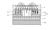
図2に示すように、搬送ベルト10は、内側(従動ローラ6に接する側)が導電体11からなり、外側(印刷ヘッド3に対向する側)に誘電体層12が設けられた2層構造とされている。誘電体12とは導電性よりも誘電性が優位であり、直流電流に対しては絶縁性を持つ物質であり、例えばプラスティック等が挙げられる。
As shown in FIG. 2, the conveying
導電体11と誘電体層12には、連続して貫通する内径の等しい円形の孔が適当な配置間隔で複数形成されている。後述するように、これらの貫通した孔は、搬送ベルト10上のシートSとその付近に電界を形成するために形成されたものであり、ここでは便宜上、導電体11の孔を通孔13、この通孔13に連通する誘電体層12の孔を開口14と称するものとする。
The
前記従動ローラ6は、少なくともその周面が導電性を有しており、その周面には、制御部38により制御される電圧印加部36によって0又は負の電位が与えられており、これに金属接触する搬送ベルト10の導電体11を0(アース)又は負の電位としている。すなわち、第1例の搬送ベルト10は0又は負の電位を有する可動電極である。
At least the peripheral surface of the driven
シートSの搬送経路にある前記搬送ベルト10の下側には、搬送ベルト10を支える矩形板状のプラテンベース15aが設置されている。このプラテンベース15aは絶縁体からなり、前記電荷印加部36に接続されて正の電位を付与される平板状の一枚電極である固定電極16aが埋込設置されている。固定電極16aは、平面視において4個の前記印刷ヘッド3を含む範囲を占めるように、印刷ヘッド3の下方に配置されている。そして、固定電極16aの表面(搬送ベルト10に対面する側)には、その表面に沿って移動する前記搬送ベルト10との接触による短絡を防止するために、誘電体層17が設けられている。
A rectangular plate-
以上の構成によれば、用紙吸着の原理を説明する図2に示すように、正電位にある固定電極16aによって誘電体層17が分極して、その表面が正電位となるので、固定電極16a側からの電気力線は、固定電極16aの直上にある搬送ベルト10の貫通した孔(通孔13及び開口14)を通って搬送ベルト10の上方に行き、搬送ベルト10の表面に載せられたシートSを下方から貫通してこれを分極するとともに、さらに下方に屈曲して搬送ベルト10の孔の周辺においてシートSを上方から貫通してこれを逆の電位に分極し、さらに搬送ベルト10の誘電体層12に到達貫通してこれを分極する。
According to the above configuration, as shown in FIG. 2 for explaining the principle of sheet adsorption, the
その結果、図2に示すように、シートS及び誘電体層12の各表裏面には互いに逆となる正負の電荷が生じるので、搬送ベルト10の固定電極16aと隣り合う範囲にある通孔13の部分及びその周辺でシートSは搬送ベルト10の誘電体層12に静電吸着される。
As a result, as shown in FIG. 2, positive and negative charges that are opposite to each other are generated on the front and back surfaces of the sheet S and the
すなわち、搬送ベルト10のうち、シートSを吸着することができる吸着領域は、固定電極16aの真上にある固定電極16aと略同一形状乃至範囲の部分だけであり、従ってこの吸着領域は、固定電極16aの真上を通過していく搬送ベルト10において固定電極16aの真上の位置に発生することとなる。
In other words, the suction area in the
従って、駆動ローラ8で駆動される搬送ベルト10にシートSを供給し、シートSを搬送ベルト10で吸着保持しながら搬送方向に沿って搬送し、その搬送速度に合せた適当なタイミングで各印刷ヘッド3を駆動してシートSに各色のインク滴を吐出して被着させれば、シートS上に所望のカラー画像を形成することができる。
Accordingly, the sheet S is supplied to the conveying
このように、第1例のシート搬送装置1aを備えた画像形成装置2aによれば、正電位の固定電極16aに対して0又は負電位の可動電極である搬送ベルト10が移動するという簡単な構成であるため、組立性及び製造コストの面で櫛歯状電極等を用いた従来の静電吸着式のシート搬送装置1に比べて有利である。また、正負の電極が上下関係で配置されており、吸着力を決定する2つの電極の間隔をより容易に精密に設定することが容易である。
As described above, according to the
また、複数の印刷ヘッド3の下方には、平板状の一枚電極である固定電極16aが配置されており、シートSを吸着した搬送ベルト10は、印刷ヘッド3の下方においては固定電極16aに吸着された状態を維持しながら移動することによりシートを搬送するので、印刷ヘッド3が配置されている固定電極16aの範囲内においては、印刷ヘッドとシートの距離を一定に保つことが出来、これによって印字品位が向上する。
A fixed
また、正負2種類の電極が、固定電極16aと可動電極としての搬送ベルト10とに分けられているので、正と負に交互に帯電した櫛歯状電極による従来の静電搬送装置のように、櫛歯状電極の電位に応じて分極した搬送ベルト10の正又は負の各帯電部分が移動により隣接する逆電位の櫛歯状電極に瞬間的に相対して搬送に抵抗を生じさせてしまうといった不都合がなく、搬送が間欠的になることがなく、円滑な動作でシートSを搬送することができるため、良好な印刷画質を得ることが可能である。
Further, since the two types of positive and negative electrodes are divided into the fixed
さらに、搬送ベルト10内に電極を内蔵した従来の静電吸着式の搬送装置に比べ、搬送ベルト10自体の厚みが小さく、表面の凹凸も少ないため、厚みむらを低減することが可能であり、搬送速度むらを低減し、この点においても良好な印刷画質を得ることが可能である。
Furthermore, since the thickness of the
また、第1例では、搬送ベルト10の表面に誘電体層12を設けたので、ユーザーが使用時又は点検時等に誤って搬送ベルト10の導電体11に触れて感電する事故を未然に防止することができ安全である。なお、搬送ベルト10に誘電体層12がなくても、搬送ベルト10の貫通した孔の部分においては、シートSとこれに対面する固定電極16aの誘電体層17は互いに逆電位に分極しているので、静電吸着力は確保され、搬送ベルト10にシートSを吸着することができる。
In the first example, since the
なお、本実施形態では搬送ベルト10に孔(通孔13及び開口14)を貫通しているが、孔の部分をポリアセチレン、ポリパラフェニレン、ポリアニリン、ポリチオフェン、ポリピロール、ポリアセン、ポリパラフェニレンビニレン等の導電性高分子としても良い。
In this embodiment, the holes (through
2.第2実施形態(第2例、図3及び図4参照)
第2例のシート搬送装置は、第1例の画像形成装置2aと同様の画像形成装置に設けられるものであり、その静電吸着の基本原理も第1例と同様であるので、画像形成装置の説明及び静電吸着機構の共通部分については説明を省略し、第1例と異なる搬送ベルト20の構造を中心に説明する。
2. Second embodiment (second example, see FIGS. 3 and 4)
The sheet conveying apparatus of the second example is provided in an image forming apparatus similar to the
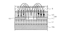
第1例のシート搬送装置においては、導電体11の通孔13と誘電体層12の開口14がすべての箇所において連通しており、すなわち、搬送ベルト10の孔はすべて完全に貫通した状態にあった。これに対し、第2例においては、図3に示すように、導電体11の通孔13に対して誘電体層12に開口が形成されていない部分があり、すなわち、搬送ベルト10の孔の一部は完全に貫通しているが、一部は通孔13はあるが開口14のない誘電体層12に被覆されて貫通していない状態となっている。
In the sheet conveying apparatus of the first example, the through
このように、第2例のシート搬送装置を備えた画像形成装置によれば、搬送ベルト20の通孔13と誘電体層12の開口が連通している部位(搬送ベルト10の孔が全体として上下に完全に貫通している部分)では、第1例で説明したのと同様の原理でシートSが搬送ベルト20に吸着される。
As described above, according to the image forming apparatus including the sheet conveying apparatus of the second example, the portion where the through
一方、搬送ベルト20の通孔13が誘電体層12によって閉塞されている部位(搬送ベルト10の孔が全体として上下に貫通していない部分)では、静電吸着力が時間の経過と共に減少していく現象が見られる。
On the other hand, at a portion where the through
まず、図3に示すように、搬送ベルト20が固定電極16aの上方に来て搬送ベルト20に吸着領域が発生する段階においては、正電位にある固定電極16aによって誘電体層17が分極して、その表面が正電位となる。そして、固定電極16a側からの電気力線は、固定電極16aの直上にある搬送ベルト20の貫通した通孔13及び誘電体層12を通って搬送ベルト20の上方に行き、搬送ベルト20の表面に載せられたシートSを下方から貫通してこれを分極するとともに、さらに下方に屈曲して搬送ベルト20の通孔13の周辺においてシートSを上方から貫通してこれを逆の電位に分極し、さらに搬送ベルト20の誘電体層12に到達貫通してこれを分極する。
First, as shown in FIG. 3, when the
その結果、図3に示すように、搬送ベルト20の通孔13の周辺領域においては、シートS及び誘電体層12の各表裏面には互いに逆となる正負の電荷が生じるので、搬送ベルト20の固定電極16aと隣り合う範囲にある通孔13の周辺でシートSは搬送ベルト20の誘電体層12に静電吸着される。
As a result, as shown in FIG. 3, in the peripheral region of the through
ところが、図4に示すように、搬送ベルト20の吸着領域が固定電極16aの上方の位置にあっても、時間が経過すると、搬送ベルト20の誘電体層12のうち、通孔13を閉塞している部分(通孔13の真上にある部分)に、周囲の搬送ベルト20の誘電体層12と同様の電荷が蓄えられていき、これがシートSを貫通していた電気力線を遮断するところとなり、シートSの表裏面には電荷が形成されなくなってシートSの誘電体層12に対する吸着力が低下していき、ついには吸着力が消滅してしまう。
However, as shown in FIG. 4, even if the adsorption region of the
従って、完全に貫通している孔と、導電体11に通孔13はあるが、開口のない誘電体層12に被覆されて貫通していない状態にある孔を、搬送ベルト20において適当な分布で形成しておけば、搬送ベルト20に生成される吸着範囲において、吸着力が維持される部分と時間の経過により吸着力が減衰していく部分とを任意の分布で配することができ、吸着力の強さと、その時間経過による減衰の態様を任意に設定することが可能となる。
Accordingly, a hole that is completely penetrated and a hole that has a through
このため、搬送ベルト20における上述した2種類の孔の配置を適宜に設定すれば、静電吸着を利用した搬送ベルト20によるシートSの搬送において、シートSの吸着開始時には必要な吸着力でシートSを搬送ベルト20の吸着範囲に確実に保持することができ、シートSの搬送中は搬送に必要な吸着力を残しつつ、余分な吸着力は時間とともに減衰していくようにすることができるので、印刷ヘッドからシートに向けて吐出されるインク滴が電荷の影響で進路を曲げられる不都合をある程度解消して画像の再現性を向上させることができ、また搬送ベルト20の移動によってシートSが搬送方向最後の印刷ヘッド3から外れた位置に来てシートSが排紙される際には、シートSの後端の吸着力が速やかに減衰して搬送ベルト20から先方への排紙動作を円滑に行うことができる。
For this reason, if the arrangement of the above-described two types of holes in the
このように、第2例のシート搬送装置を備えた画像形成装置によれば、簡単な構成によって、インク滴落下に与える電界の影響が低減し、画像の再現性が向上し、シート排出時の分離性(搬送ベルト20からの剥離性)が向上し、排出後の用紙揃え性が向上する。 As described above, according to the image forming apparatus including the sheet conveying apparatus of the second example, the influence of the electric field on the ink droplet dropping is reduced by a simple configuration, the image reproducibility is improved, and the sheet is discharged. Separability (removability from the conveyor belt 20) is improved, and paper alignment after discharge is improved.
3.第3実施形態(第3例、図5及び図6参照)
第3例のシート搬送装置1bは、第1例の画像形成装置2aと同様の画像形成装置2bに設けられるものであり、その静電吸着の基本原理は第1例と同様であるので、画像形成装置2bの説明及び静電吸着機構の共通部分については説明を省略し、第1例と異なる固定電極16bの構造を中心に説明する。
3. 3rd Embodiment (refer 3rd example, FIG.5 and FIG.6)
The
図5に示すように、シートSの搬送経路にある前記搬送ベルト10の下側には、搬送ベルト10を支える矩形板状のプラテンベース15bが設置されている。このプラテンベース15bは絶縁体からなり、電荷印加部36に接続されて正の電位を付与される複数(第3例では5個)の固定電極16bが所定間隔をおいて埋込設置されている。固定電極16bは、前記印刷ヘッド3とは相対しない位置、具体的には搬送方向について最も上流にある印刷ヘッド3(C)の手前の位置と、4個の印刷ヘッド3(C、K、M、Y)の間に相当する3つの位置と、搬送方向について最も下流にある印刷ヘッド3(Y)の先方の位置とに配置されている。そして、各固定電極16bの表面(搬送ベルト10に対面する側)には、その表面に沿って移動する前記搬送ベルト10との接触による短絡を防止するために、誘電体層17が設けられている。
As illustrated in FIG. 5, a rectangular plate-
第3例によれば、図6に示すように、搬送ベルト10のうち、シートSを吸着することができる吸着領域Hは、固定電極16bの真上にある固定電極16bと略同一形状乃至範囲の部分だけであり、従ってこの吸着領域Hは、各固定電極16bの真上を通過していく搬送ベルト10において固定電極16bの真上の位置に固定電極16bと略同一の配置間隔で発生することとなる。
According to the third example, as shown in FIG. 6, in the
第3例によれば、第1例と略同様の作用、効果が得られるが、固定電極16bは間隔をおいた複数の電極から構成される分割構造なので、第1例のような一枚板状の固定電極16aに比べて移動するベルト10と接触、吸着して抵抗が生じる面積が小さいので、搬送負荷は第1例よりも軽減される利点がある。
According to the third example, substantially the same operation and effect as the first example can be obtained, but the fixed
また、各印刷ヘッド3は固定電極16bの位置を避けて配置されており、印刷ヘッド3の下方には固定電極16bがなく、各印刷ヘッド3から下方に吐出されるインク滴が固定電極16bの電界によって飛行曲がりを生じる不都合が生じにくいので、第1例よりもさらに良好な画質を得ることができる。
Further, each
さらに、このような第3例において、前述した第2例(図3及び図4)のように、貫通孔と未貫通孔を適宜の割合と分布で配置した搬送ベルトとすれば、固定電極16bと固定電極16bの間にある印刷ヘッド3の下方領域において、シートSの帯電状態の解消が一層迅速に行われるので、印刷ヘッド3からシートSに向けて吐出されるインク滴が電荷の影響で進路を曲げられる不都合がさらに確実に解消され、また上記排紙時にシートSの帯電による排紙台上でのシート揃えの悪化がより確実に低減する。
Further, in such a third example, if the conveyance belt is arranged with through holes and non-through holes in an appropriate ratio and distribution as in the second example (FIGS. 3 and 4), the fixed
次に、図7は、第3例の変形例を示す全体構造図である。
本変形例のシート搬送装置1bを有する画像形成装置2bの構造は、従動ローラ6に対して電荷印加部36が0又は負の電位を与えている点と、搬送される画像記録媒体が枚葉状でなくロール状のシートS’である点が、第3例と異なり、その他の点は第3例と同一である。このように、本発明の実施形態において、印刷用紙やフィルム等のシート状の印刷媒体だけでなく、ロール状に巻装されたシート状物を連続的に搬送して高画質の画像形成を行うこともできる。なお、図7ではレジストローラ4、及び従動ローラ5は省略してある。
Next, FIG. 7 is an overall structural diagram showing a modification of the third example.
The structure of the
4.第4実施形態(第4例、図8参照)
第4例のシート搬送装置1cを備えた画像形成装置2cについて説明する。
第4例の説明においては、第3例の変形例(図7)と機能上実質的に同一である部分については図7中の符号と同一の符号を図8中に付して適宜説明を省略し、第3例の変形例(図7)との相違点であって、第4例の特徴に係る部分を中心として説明するものとする。
4). Fourth embodiment (fourth example, see FIG. 8)
An
In the description of the fourth example, portions substantially the same as the modification of the third example (FIG. 7) are functionally the same as those in FIG. The description will be omitted, focusing on the part of the fourth example that is different from the modification of the third example (FIG. 7).
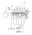
図8に示すように、シートSの搬送方向について搬送ベルト10の下流側には、画像形成されたシートSを吸着しながら下流に排出する排出ローラ40が隣接して設けられている。この排出ローラ40は、排紙性を良くするため、前記搬送ベルト10よりも大きな速度で回転し、シートSを搬送しながら印刷ヘッド3によって行う画像形成中は常時駆動されている。なお、排出ローラ40での吸着力は、排出ローラ40の下方に設けられた吸引ファン41であり、その吸引(風)による吸着力は搬送ベルト10のみによる吸着力よりも大きい。
As shown in FIG. 8, a
ここで、本例のシート搬送装置1cは、排出ローラ40を含めたシート搬送方向の寸法が小型化されており、シート搬送方向について最下流にある印刷ヘッド3(Y)と前記排出ローラ40の間隔がシートSの搬送方向の長さよりも短いコンパクトな構成となっている。コンパクトな構成であることは種々の点で好ましいが、最下流の印刷ヘッド3(Y)がシートSの後端部に画像形成しているとき、当該シートSの先端部が常時駆動の排出ローラ40にかかってその駆動力を受けるので、何らの手当てをしない場合は、最下流の印刷ヘッド3(Y)で画像形成中に排出ローラ40がシートSを引っ張って色ずれを生じる可能性がある。
Here, in the
しかしながら、本例のシート搬送装置1cでは、シートSの搬送方向について最下流にある印刷ヘッド3(Y)と排出ローラ40との間に静電吸着電極50aが設けられており、最下流の印刷ヘッド3(Y)と排出ローラ40の両方にシートSがかかっている場合に、この静電吸着電極50aによってシートSを押さえ、シートSが排出方向に引っ張られて色ずれが生じないように構成されている。
However, in the
この静電吸着電極50aは、前述した固定電極16bと共にプラテンベース15bに設けられた電極であるが、固定電極16bとは構造的、電気的に独立しており、固定電極16bよりも高い正の電位が電荷印加部36によって印可され、これにより固定電極16bが発生する電界よりも強い電界を発生し、以て画像形成中であるシートSの後端部における搬送ベルト10への吸着力を増強するようになっている。
The
以上の構成によれば、制御部38によって電荷印加部36を適宜に制御しつつ、駆動ローラ8を駆動源7により回動して搬送ベルト10を搬送方向に循環して移動させれば、固定電極16bにより生成される電界によって搬送ベルト10の上に静電吸着されたシートSは、印刷ヘッド3の下方で各印刷ヘッド3に沿って搬送されていく。
According to the above configuration, the
そして、搬送ベルト10によるシートSの搬送に同期して各印刷ヘッド3を駆動すれば、シートS上に所望の画像を形成できる。ここで、シートSの後端部が最下流の印刷ヘッド3(Y)による画像形成を受けている時、当該シートSの先端部はすでに排出ローラ40にかかり、吸引ファン41の吸着力により排出ローラ40に吸着されながら、搬送ベルト10よりも大きな速度で排出方向に引っ張られる。
A desired image can be formed on the sheet S by driving each
しかしながら、シートSの後端部は、最下流の印刷ヘッド3(Y)のシート搬送方向下流に隣接して設けられた静電吸着電極50aによる電界の影響を受け、搬送ベルト10の表面に対する静電吸着力を増大させているので、シートSは排出ローラ40に引かれて排出方向にずれることはなく、最下流の印刷ヘッド3(Y)において色ずれの不都合が生じる恐れはない。このように、印刷ヘッド3によってシートSに画像形成が行われている間は、常に搬送ベルト10側における吸着力が、排出ローラ40における吸着力を上回るようになっている。
However, the rear end portion of the sheet S is affected by an electric field by the
そして、印刷ヘッド3による画像形成が終了すると、静電吸着電極50aに対する電荷印加部36による正電位の印加が打ち切られて電界が消滅し、強い静電吸着力が消滅するので、排出ローラ40における吸着力が、搬送ベルト10側における吸着力をはるかに上回るようになり、画像形成が完了したシートSは排出ローラ40によって急加速排出されることとなる。
When the image formation by the
なお、静電吸着電極50aにより搬送ベルト10に生じるシートSの吸着力は、排出ローラ40における吸着力より常時大きくしてもよいし、シートSが最下流の印刷ヘッド3(Y)と排出ローラ40にかかるタイミングでのみ大きくしてもよい。
Note that the suction force of the sheet S generated on the
また、静電吸着電極50aの制御においては、制御部38及び電荷印加部36は、シートSが最下流の印刷ヘッド3(Y)から抜けたことを、例えば用紙先端検出センサからの検出信号とエンコーダパルス数から予測する等して検知し、静電吸着電極50aの吸着力を可変させることとしてもよい。
Further, in the control of the
従来は、画像形成中のシート搬送速度が排出ローラ40の速度に影響されないように最終印刷ヘッド3と排出ローラ40の間隔をシートS以上の長さにする必要があり、装置が大型化していた。逆に、装置を小型化したい場合は、色ずれが発生しないように排出ローラ40の排出速度を搬送ベルト35による速度以下としていたため排出ジャムや排紙不揃いが生じていた。
Conventionally, it is necessary to make the distance between the
しかし、第4例の構成によれば、最終印刷ヘッド3と排出ローラ40の間に静電吸着電極50aを設けたので、排出ローラ40の排出速度を落とすことなく、シートSの搬送方向の寸法をコンパクトに構成することができた。
However, according to the configuration of the fourth example, since the
5.第5実施形態(第5例、図9参照)
図9は、第1例における固定電極16aを有するシート搬送装置1a(図1参照)に、第4例におけるシート搬送装置1c(図8参照)の静電吸着電極50aを組み合わせたものであり、図9中、機能又は名称が対応する構成部分には既出の符号を付して前述の各説明(構成、作用、効果等)を援用する。
5. Fifth embodiment (see fifth example, FIG. 9)
FIG. 9 is a combination of the
6.第6実施形態(第6例、図10参照)
第6例のシート搬送装置は、静電吸着電極の構造が第4例、第5例と異なるだけで、ぞれ以外の構成は同一であるので、静電吸着電極の部分のみを図示及び説明する。
第4例、第5例の静電吸着電極50aは、搬送ベルト35の下に設けられた単一矩形状の電極で正電位が印加されるものであったが、第6例における静電吸着電極60は、図10に示すように、第4例、第5例において静電吸着電極50aが設けられていたのとほぼ同位置に設けられた櫛歯状の電極である。この櫛歯電極は隣接する各櫛歯61,62が交互に正又は負(又は0)の電位に接続されており、互いに絶縁されている。本例によっても、第4例、第5例と同様の作用効果を得ることができる。
6). Sixth embodiment (see sixth example, FIG. 10)
The sheet conveying apparatus of the sixth example is different from the fourth example and the fifth example only in the structure of the electrostatic chucking electrode, and the other configuration is the same. Therefore, only the electrostatic chucking electrode portion is shown and described. To do.
In the fourth and fifth examples, the
7.第7実施形態(第7例、図11参照)
第4例乃至第6例の画像形成装置において、シートの後端部の吸着力を排出ローラでの吸着力よりも強くすることにより、シートが排出方向に引っ張られて色ずれが生じないように構成したシート搬送装置の技術は、例えば「背景技術」の項で説明したような一般的な静電搬送装置においても有効に適用することができる。そこで、第7例においては、帯電ローラ型の静電搬送装置を有する画像形成装置2dにおいて、排出ローラでの吸着力よりも強い吸着力でシートの後端部を吸着する静電吸着電極を設けた例について説明する。
7). Seventh embodiment (seventh example, see FIG. 11)
In the image forming apparatuses of the fourth to sixth examples, the sheet is pulled in the discharge direction so that color misregistration does not occur by making the suction force of the trailing edge of the sheet stronger than the suction force of the discharge roller. The technology of the configured sheet conveying apparatus can be effectively applied to, for example, a general electrostatic conveying apparatus as described in “Background Art”. Therefore, in the seventh example, in the
このシート搬送装置30は、搬送方向上流側の0又は負電位に接続された従動ローラ31と、搬送方向下流側に設けられて駆動源32に連動連結された駆動ローラ33と、従動ローラ31と駆動ローラ33の中間下方に配置されたテンションローラ34に被誘電体からなる無端状の搬送ベルト35が掛け回されている。
The
さらに、従動ローラ31に掛け回された搬送ベルト35の外面側には、電荷印加部36に接続されて正電位とされた帯電ローラ37が設けられており、0又は負電位に接続されて対極となる前記従動ローラ31との間で搬送ベルト35を挟持するようになっている。なお、電荷印加部36は、制御部38に接続されており、接続先の電極部材に所望の正電位を与えることができるように制御部38によって制御される。
Further, on the outer surface side of the conveying
正電位の前記帯電ローラ37は、0又は負電位の対極である前記従動ローラ31とともに、搬送ベルト35を挟み込む形で電界を発生させ、搬送ベルト35を分極させるための電極部材である。帯電ローラ37は芯材が金属からなり、その表面を例えば1×10¹²Ω 程度の抵抗率を有するゴム材等で形成し、搬送に必要な摩擦を発生させている。
The charging
搬送ベルト35は、前述した通り被誘電体からなる。被誘電体とは、それ自身が帯電し、帯電した被搬送物(シートS)を吸着することができる物質であり。第3例では、1×10¹²〜1×10¹⁴Ω程度のポリイミドフィルムを使用する。
The
従って、搬送ベルト35は、図11(b)に示すように、シートSを吸着する搬送経路(循環するベルトの上側の部分)においては表面(上側)が負に帯電し、裏面(下側)が正に帯電する。この搬送ベルト35の上に被印刷媒体である印刷用紙等のシートSが供給されれば、シートSは搬送ベルト35に接する側(下面)が正に、表側(上面)が負にそれぞれ分極・帯電して搬送ベルト35に静電吸着されることとなる。
Accordingly, as shown in FIG. 11B, the front surface (upper side) of the
従って、制御部38によって電荷印加部36を適当に制御しつつ、下方に付勢されたテンションローラ34によって搬送ベルト35に適度な張力を与えながら、駆動ローラ33を駆動源32により回動して搬送ベルト35を搬送方向に循環して移動させれば、搬送ベルト35の上に静電吸着されたシートSを印刷ヘッド3の下方で各印刷ヘッド3に沿って搬送していくことができる。すなわち、これらローラに掛け回されて移動する搬送ベルト35のうち、印刷ヘッド3に隣接して水平に移動する部分がシートSの搬送経路となる。
Accordingly, the driving
シートSの搬送経路にある前記搬送ベルト35の下側には、搬送ベルト35を支える矩形板状のプラテンベース15が設置されている。このプラテンベース15は絶縁体からなり、搬送ベルト35を支える役割を有している。
A rectangular plate-like platen base 15 that supports the
また、シートSの搬送方向について搬送ベルト35の下流側には、画像形成されたシートSを吸着しながら下流に排出する排出ローラ40が隣接して設けられている。この排出ローラ40は、排紙性を良くするため、前記搬送ベルト35よりも大きな速度で回転し、シートSを搬送しながら印刷ヘッド3によって行う画像形成中は常時駆動されている。なお、排出ローラ40での吸着力は、排出ローラ40の下方に設けられた吸引ファン41であり、その吸引(風)による吸着力は搬送ベルト35のみによる吸着力よりも大きい。
Further, on the downstream side of the
ここで、本例のシート搬送装置30は、排出ローラ40を含めたシート搬送方向の寸法が小型化されており、シート搬送方向について最下流にある印刷ヘッド3(Y)と前記排出ローラ40の間隔がシートSの搬送方向の長さよりも短いコンパクトな構成となっている。コンパクトな構成であることは種々の点で好ましいが、最下流の印刷ヘッド3(Y)がシートSの後端部に画像形成しているとき、当該シートSの先端部が常時駆動の排出ローラ40にかかってその駆動力を受けるので、何らの手当てをしない場合は、最下流の印刷ヘッド3(Y)で画像形成中に排出ローラ40がシートSを引っ張って色ずれを生じる可能性がある。
Here, in the
しかしながら、本例のシート搬送装置30では、シートSの搬送方向について最下流にある印刷ヘッド3(Y)と排出ローラ40との間に静電吸着電極50bが設けられており、最下流の印刷ヘッド3(Y)と排出ローラ40の両方にシートSがかかっている場合に、この静電吸着電極50bによってシートSを押さえ、シートSが排出方向に引っ張られて色ずれが生じないように構成されている。
However, in the
この静電吸着電極50bは、最下流の印刷ヘッド3(Y)と排出ローラ40の間において、搬送ベルト35を挟む上下の位置に、搬送ベルト35に接触しないように設けられた正電極板51(上側)及び負電極板52(下側)からなり、両電極板51,52の間に生じる電界によってシートSの搬送ベルト35に対する吸着力を増強するようになっている。
The
以上の構成によれば、制御部38によって電荷印加部36を適当に制御しつつ、駆動ローラ33を駆動源32により回動して搬送ベルト35を搬送方向に循環して移動させれば、搬送ベルト35の上に静電吸着されたシートSは印刷ヘッド3の下方で各印刷ヘッド3に沿って搬送されていく。
According to the above configuration, if the
そして、搬送ベルト35によるシートSの搬送に同期して各印刷ヘッド3を駆動すれば、シートS上に所望の画像を形成できる。ここで、シートSの後端部が最下流の印刷ヘッド3(Y)による画像形成を受けている時、当該シートSの先端部はすでに排出ローラ40にかかり、その吸着力により排出ローラ40に吸着されながら、搬送ベルト35よりも大きな速度で排出方向に引っ張られている。
A desired image can be formed on the sheet S by driving each
しかしながら、シートSの略中間部分は、最下流の印刷ヘッド3(Y)と排出ローラ40の間で静電吸着電極50bによる電界の影響を受け、搬送ベルト35の表面に対する静電吸着力を増大させているので、シートSは排出ローラ40に引かれて排出方向にずれることはなく、最下流の印刷ヘッド3(Y)において色ずれの不都合が生じる恐れはない。このように、印刷ヘッド3によってシートSに画像形成が行われている間は、常に搬送ベルト35側における吸着力が、排出ローラ40における吸着力を上回るようになっている。
However, the substantially intermediate portion of the sheet S is affected by the electric field generated by the
そして、印刷ヘッド3による画像形成が終了すると、静電吸着電極50bの正電極板51に対する正電位の印加が打ち切られて電界が消滅し、静電吸着力の増強がなくなるので、搬送ベルト35側における吸着力を、排出ローラ40における吸着力がはるかに上回るようになり、画像形成が完了したシートSは排出ローラ40によって急加速排出されるこ
When the image formation by the
なお、静電吸着電極50bにより、搬送ベルト35におけるシートSの吸着力を排出ローラ40における吸着力よりも常時大きくしてもよいし、シートSが最下流の印刷ヘッド3(Y)と排出ローラ40にかかるタイミングでのみ大きくしてもよい。
The
また、静電吸着電極50bの制御においては、制御部38及び電荷印加部36は、シートSが最下流の印刷ヘッド3(Y)から抜けたことを、例えば用紙先端検出センサからの検出信号とエンコーダパルス数から予測する等して検知し、静電吸着電極50bの吸着力を可変させることとしてもよい。
Further, in the control of the
従来は、画像形成中のシート搬送速度が排出ローラ40の速度に影響されないように最終印刷ヘッド3と排出ローラ40の間隔をシートS以上の長さにする必要があり、装置が大型化していた。逆に、装置を小型化したい場合は、色ずれが発生しないように排出ローラ40の排出速度を搬送ベルト35による速度以下としていたため排出ジャムや排紙不揃いが生じていた。
Conventionally, it is necessary to make the distance between the
しかし、第7例の構成によれば、最終印刷ヘッド3と排出ローラ40の間に静電吸着電極50bを設けたので、排出ローラ40の排出速度を落とすことなく、シートSの搬送方向の寸法をコンパクトに構成することができた。
However, according to the configuration of the seventh example, since the
8.第8実施形態(第8例、図12参照)
図12は、第7例におけるシート搬送装置30(図11参照)において、その静電吸着電極50bを第6例における静電吸着電極60(図10参照)に替えたものであり、図12中、機能又は名称が対応する構成部分には既出の符号を付して前述の各説明(構成、作用、効果等)を援用する。
8). Eighth embodiment (eighth example, see FIG. 12)
FIG. 12 shows the sheet conveying apparatus 30 (see FIG. 11) in the seventh example, in which the
以上説明した各実施形態のシート搬送装置は、インクを吐出してシート上に画像を形成する印刷ヘッドを備えた画像形成装置においてシートを搬送するための手段として用いられていたが、本発明は必ずしもこのようなインクジェット方式の画像形成装置にのみ適用されるものではなく、例えば孔版印刷装置におけるシート搬送手段としても適用可能であるし、その他の画像形成原理を用いた画像形成装置乃至印刷装置においても適用可能であり、さらには画像形成装置のシート搬送手段に限定されることなく、産業上の種々の用途に対応してシートを安定的に搬送できる手段として有効利用できるものである。 The sheet conveying apparatus according to each embodiment described above has been used as a means for conveying a sheet in an image forming apparatus including a print head that forms an image on a sheet by discharging ink. The present invention is not necessarily applied only to such an ink jet image forming apparatus, and can be applied, for example, as a sheet conveying unit in a stencil printing apparatus, or in an image forming apparatus or printing apparatus using other image forming principles. In addition, the present invention is not limited to the sheet conveying unit of the image forming apparatus, and can be effectively used as a unit capable of stably conveying a sheet corresponding to various industrial uses.
1a,1b,1c,30…シート搬送装置
2a,2b,2c,2d…画像形成装置
3…印刷ヘッド
10,20…搬送ベルト
11…導電体
12…搬送ベルトの誘電体層
13…導電体の通孔
14…搬送ベルトの誘電体層の開口
16a,16b…固定電極
17…固定電極の誘電体層
40…排出ローラ
50a,50b,60…静電吸着電極
51…正電極板
52…負電極板
S,S’…シート
DESCRIPTION OF
Claims (10)
第1電位が与えられるとともに、前記シートが搬送される側の表面には誘電体層が設けられた固定電極と、
前記固定電極の誘電体層に相対してシートの搬送方向に循環して駆動され、第2電位が与えられるとともに、前記固定電極からの電気力線が貫通する複数の通孔が形成されて前記固定電極の側とは反対側の表面にシートが静電吸着される導電体からなる搬送ベルトと、
を有することを特徴とするシート搬送装置。 In a sheet conveying apparatus that conveys a sheet,
A fixed electrode provided with a dielectric layer on the surface on which the first potential is applied and the sheet is conveyed;
Driven by circulating in the sheet conveying direction relative to the dielectric layer of the fixed electrode, a second electric potential is applied, and a plurality of through holes through which lines of electric force from the fixed electrode pass are formed, and A transport belt made of a conductor on which a sheet is electrostatically adsorbed on the surface opposite to the fixed electrode;
A sheet conveying apparatus comprising:
前記印刷ヘッドの下方に配置され、第1電位が与えられるとともに、前記印刷ヘッド側の表面には誘電体層が設けられた固定電極と、
前記固定電極の誘電体層に相対してシートの搬送方向に循環して駆動され、第2電位が与えられるとともに、前記固定電極からの電気力線が貫通する複数の通孔が形成されて前記印刷ヘッド側の表面にシートが静電吸着される導電体からなる搬送ベルトと、
を有することを特徴とするシート搬送装置。 In a sheet conveying device that is provided in an image forming apparatus that forms an image on a sheet by discharging ink from a plurality of print heads arranged at intervals to the sheet, and in which the sheet is conveyed along the print head,
A fixed electrode that is disposed below the print head and is provided with a first potential, and a dielectric layer is provided on the surface of the print head;
Driven by circulating in the sheet conveying direction relative to the dielectric layer of the fixed electrode, a second electric potential is applied, and a plurality of through holes through which lines of electric force from the fixed electrode pass are formed, and A transport belt made of a conductor on which a sheet is electrostatically attracted to the surface on the print head side;
A sheet conveying apparatus comprising:
シートの搬送方向について最下流にある前記印刷ヘッドと前記排出ローラとの間に設けられ、シートの搬送方向について最下流にある前記印刷ヘッドと前記排出ローラの両方にシートがかかっている場合に前記排出ローラの吸着力よりも強い静電吸着力を生じる静電吸着電極と、The sheet is provided between the print head and the discharge roller located on the most downstream side in the sheet conveyance direction, and the sheet is applied to both the print head and the discharge roller located on the most downstream side in the sheet conveyance direction. An electrostatic attracting electrode that produces an electrostatic attracting force stronger than the attracting force of the discharge roller;
を有することを特徴とする請求項2、6、7、8、9のいずれか一つに記載のシート搬送装置。10. The sheet conveying apparatus according to claim 2, wherein the sheet conveying apparatus includes:
Priority Applications (3)
| Application Number | Priority Date | Filing Date | Title |
|---|---|---|---|
| JP2006346303A JP4648297B2 (en) | 2006-12-22 | 2006-12-22 | Sheet transport device |
| US12/310,795 US20100021219A1 (en) | 2006-12-22 | 2007-10-03 | Sheet transporting device |
| PCT/JP2007/069786 WO2008078446A1 (en) | 2006-12-22 | 2007-10-03 | Sheet transporting device |
Applications Claiming Priority (1)
| Application Number | Priority Date | Filing Date | Title |
|---|---|---|---|
| JP2006346303A JP4648297B2 (en) | 2006-12-22 | 2006-12-22 | Sheet transport device |
Publications (3)
| Publication Number | Publication Date |
|---|---|
| JP2008156049A JP2008156049A (en) | 2008-07-10 |
| JP2008156049A5 JP2008156049A5 (en) | 2009-09-17 |
| JP4648297B2 true JP4648297B2 (en) | 2011-03-09 |
Family
ID=39562240
Family Applications (1)
| Application Number | Title | Priority Date | Filing Date |
|---|---|---|---|
| JP2006346303A Active JP4648297B2 (en) | 2006-12-22 | 2006-12-22 | Sheet transport device |
Country Status (3)
| Country | Link |
|---|---|
| US (1) | US20100021219A1 (en) |
| JP (1) | JP4648297B2 (en) |
| WO (1) | WO2008078446A1 (en) |
Families Citing this family (10)
| Publication number | Priority date | Publication date | Assignee | Title |
|---|---|---|---|---|
| JP4591579B2 (en) | 2008-08-29 | 2010-12-01 | ブラザー工業株式会社 | Sheet guidance device |
| JP4780217B2 (en) * | 2009-03-30 | 2011-09-28 | ブラザー工業株式会社 | Recording device |
| US20110026046A1 (en) | 2009-07-31 | 2011-02-03 | Silverbrook Research Pty Ltd | Wide format printer with scanner to align printhead assembly |
| JP2011051119A (en) * | 2009-08-31 | 2011-03-17 | Riso Kagaku Corp | Ink jet printer |
| US8794727B2 (en) * | 2012-02-07 | 2014-08-05 | Delphax Technologies Inc. | Multiple print head printing apparatus and method of operation |
| US8998403B2 (en) * | 2012-11-06 | 2015-04-07 | Xerox Corporation | Media tacking to media transport using a media tacking belt |
| JP6632190B2 (en) * | 2014-03-25 | 2020-01-22 | キヤノン株式会社 | Liquid ejection device and liquid ejection method |
| JP2019098581A (en) * | 2017-11-30 | 2019-06-24 | 株式会社ミマキエンジニアリング | Printer and printing method |
| US10915043B2 (en) | 2018-09-04 | 2021-02-09 | Fuji Xerox Co., Ltd. | Image forming apparatus |
| JP2021149002A (en) * | 2020-03-19 | 2021-09-27 | 富士フイルムビジネスイノベーション株式会社 | Image forming apparatus |
Citations (5)
| Publication number | Priority date | Publication date | Assignee | Title |
|---|---|---|---|---|
| JPS63277148A (en) * | 1987-05-01 | 1988-11-15 | Canon Inc | Image forming device |
| JPH0213975A (en) * | 1988-07-01 | 1990-01-18 | Bando Chem Ind Ltd | Conveying device for dielectric sheet |
| JPH11151822A (en) * | 1997-11-20 | 1999-06-08 | Canon Inc | Recorder |
| JP2006149156A (en) * | 2004-11-24 | 2006-06-08 | Creative Technology:Kk | Electrostatic attractor, and transfer method of sheet type attracted material using its electrostatic attractor |
| JP2006232500A (en) * | 2005-02-25 | 2006-09-07 | Fuji Xerox Co Ltd | Image recorder |
Family Cites Families (6)
| Publication number | Priority date | Publication date | Assignee | Title |
|---|---|---|---|---|
| EP0313088B1 (en) * | 1987-10-23 | 1995-01-04 | Fujitsu Limited | A suction-type sheet-carrying mechanism for an image-forming apparatus |
| ATE209573T1 (en) * | 1993-07-28 | 2001-12-15 | Canon Kk | INKJET RECORDING APPARATUS AND INKJET RECORDING METHOD |
| US6438350B1 (en) * | 1999-04-26 | 2002-08-20 | Canon Kabushiki Kaisha | Image reading apparatus and image forming apparatus |
| JP4563650B2 (en) * | 2003-01-28 | 2010-10-13 | 株式会社リコー | Paper conveying apparatus and image forming apparatus |
| US6997549B2 (en) * | 2004-02-26 | 2006-02-14 | Hewlett-Packard Development Company, L.P. | Media hold down system |
| JP6087178B2 (en) * | 2013-03-08 | 2017-03-01 | 日本メナード化粧品株式会社 | Solid powder cosmetic |
-
2006
- 2006-12-22 JP JP2006346303A patent/JP4648297B2/en active Active
-
2007
- 2007-10-03 WO PCT/JP2007/069786 patent/WO2008078446A1/en active Application Filing
- 2007-10-03 US US12/310,795 patent/US20100021219A1/en not_active Abandoned
Patent Citations (5)
| Publication number | Priority date | Publication date | Assignee | Title |
|---|---|---|---|---|
| JPS63277148A (en) * | 1987-05-01 | 1988-11-15 | Canon Inc | Image forming device |
| JPH0213975A (en) * | 1988-07-01 | 1990-01-18 | Bando Chem Ind Ltd | Conveying device for dielectric sheet |
| JPH11151822A (en) * | 1997-11-20 | 1999-06-08 | Canon Inc | Recorder |
| JP2006149156A (en) * | 2004-11-24 | 2006-06-08 | Creative Technology:Kk | Electrostatic attractor, and transfer method of sheet type attracted material using its electrostatic attractor |
| JP2006232500A (en) * | 2005-02-25 | 2006-09-07 | Fuji Xerox Co Ltd | Image recorder |
Also Published As
| Publication number | Publication date |
|---|---|
| JP2008156049A (en) | 2008-07-10 |
| WO2008078446A1 (en) | 2008-07-03 |
| US20100021219A1 (en) | 2010-01-28 |
Similar Documents
| Publication | Publication Date | Title |
|---|---|---|
| JP4648297B2 (en) | Sheet transport device | |
| JP4295663B2 (en) | Image forming apparatus | |
| KR100760406B1 (en) | Image Forming Apparatus | |
| JP5842546B2 (en) | Inkjet recording device | |
| JP2008156049A5 (en) | ||
| US8303105B2 (en) | Medium feeding apparatus and image recording apparatus | |
| JP4780217B2 (en) | Recording device | |
| JP4389782B2 (en) | Inkjet printer for textile printing and method for producing textile printed matter | |
| JP4937023B2 (en) | Sheet transport device | |
| JP2007230035A (en) | Droplet ejection apparatus | |
| JP6221211B2 (en) | Dielectric barrier discharge generator, sheet material reforming apparatus, image forming apparatus, and printed matter production method | |
| JP3139539U (en) | Sheet transport device | |
| JP4280470B2 (en) | Sheet conveying method and recording apparatus | |
| US8596778B2 (en) | Ink jet recording apparatus | |
| JP2017132043A (en) | Printer | |
| JP4470777B2 (en) | Droplet discharge device | |
| JP2024001855A (en) | Conveyance device | |
| JP2007126252A (en) | Ink jet recording device | |
| JP5782800B2 (en) | Image forming apparatus | |
| JP2017128032A (en) | Printing apparatus | |
| JP2007210112A (en) | Liquid droplet discharge apparatus | |
| JP2007190750A (en) | Liquid droplet jet device | |
| JP5495115B2 (en) | Image forming apparatus | |
| JP2014141030A (en) | Medium conveying device, recording device | |
| JP4449914B2 (en) | Droplet discharge device |
Legal Events
| Date | Code | Title | Description |
|---|---|---|---|
| A521 | Request for written amendment filed |
Free format text: JAPANESE INTERMEDIATE CODE: A523 Effective date: 20090803 |
|
| A621 | Written request for application examination |
Free format text: JAPANESE INTERMEDIATE CODE: A621 Effective date: 20090803 |
|
| A131 | Notification of reasons for refusal |
Free format text: JAPANESE INTERMEDIATE CODE: A131 Effective date: 20100914 |
|
| A521 | Request for written amendment filed |
Free format text: JAPANESE INTERMEDIATE CODE: A523 Effective date: 20101028 |
|
| TRDD | Decision of grant or rejection written | ||
| A01 | Written decision to grant a patent or to grant a registration (utility model) |
Free format text: JAPANESE INTERMEDIATE CODE: A01 Effective date: 20101130 |
|
| A01 | Written decision to grant a patent or to grant a registration (utility model) |
Free format text: JAPANESE INTERMEDIATE CODE: A01 |
|
| A61 | First payment of annual fees (during grant procedure) |
Free format text: JAPANESE INTERMEDIATE CODE: A61 Effective date: 20101209 |
|
| FPAY | Renewal fee payment (event date is renewal date of database) |
Free format text: PAYMENT UNTIL: 20131217 Year of fee payment: 3 |
|
| R150 | Certificate of patent or registration of utility model |
Ref document number: 4648297 Country of ref document: JP Free format text: JAPANESE INTERMEDIATE CODE: R150 Free format text: JAPANESE INTERMEDIATE CODE: R150 |
|
| R250 | Receipt of annual fees |
Free format text: JAPANESE INTERMEDIATE CODE: R250 |
|
| R250 | Receipt of annual fees |
Free format text: JAPANESE INTERMEDIATE CODE: R250 |
|
| R250 | Receipt of annual fees |
Free format text: JAPANESE INTERMEDIATE CODE: R250 |
|
| R250 | Receipt of annual fees |
Free format text: JAPANESE INTERMEDIATE CODE: R250 |
|
| R250 | Receipt of annual fees |
Free format text: JAPANESE INTERMEDIATE CODE: R250 |
|
| R250 | Receipt of annual fees |
Free format text: JAPANESE INTERMEDIATE CODE: R250 |
|
| R250 | Receipt of annual fees |
Free format text: JAPANESE INTERMEDIATE CODE: R250 |
|
| R250 | Receipt of annual fees |
Free format text: JAPANESE INTERMEDIATE CODE: R250 |
|
| R250 | Receipt of annual fees |
Free format text: JAPANESE INTERMEDIATE CODE: R250 |
|
| R250 | Receipt of annual fees |
Free format text: JAPANESE INTERMEDIATE CODE: R250 |
|
| R250 | Receipt of annual fees |
Free format text: JAPANESE INTERMEDIATE CODE: R250 |