JP4645886B2 - Sewing machine with thread trimmer - Google Patents
Sewing machine with thread trimmer Download PDFInfo
- Publication number
- JP4645886B2 JP4645886B2 JP2004295431A JP2004295431A JP4645886B2 JP 4645886 B2 JP4645886 B2 JP 4645886B2 JP 2004295431 A JP2004295431 A JP 2004295431A JP 2004295431 A JP2004295431 A JP 2004295431A JP 4645886 B2 JP4645886 B2 JP 4645886B2
- Authority
- JP
- Japan
- Prior art keywords
- thread
- needle
- knife
- plate
- movable knife
- Prior art date
- Legal status (The legal status is an assumption and is not a legal conclusion. Google has not performed a legal analysis and makes no representation as to the accuracy of the status listed.)
- Active
Links
Images


Classifications
-
- D—TEXTILES; PAPER
- D05—SEWING; EMBROIDERING; TUFTING
- D05B—SEWING
- D05B65/00—Devices for severing the needle or lower thread
-
- D—TEXTILES; PAPER
- D05—SEWING; EMBROIDERING; TUFTING
- D05B—SEWING
- D05B37/00—Devices incorporated in sewing machines for slitting, grooving, or cutting
- D05B37/04—Cutting devices
- D05B37/06—Cutting devices with oscillating tools
-
- D—TEXTILES; PAPER
- D05—SEWING; EMBROIDERING; TUFTING
- D05B—SEWING
- D05B57/00—Loop takers, e.g. loopers
- D05B57/02—Loop takers, e.g. loopers for chain-stitch sewing machines, e.g. oscillating
-
- D—TEXTILES; PAPER
- D05—SEWING; EMBROIDERING; TUFTING
- D05B—SEWING
- D05B73/00—Casings
- D05B73/04—Lower casings
- D05B73/12—Slides; Needle plates
Description
本発明は、例えばTシャツの首周りや袖口の縫合やカバーリングなど筒状部位の縫製に適用される糸切り装置付きミシンに関する。詳しくは、筒状部位の縫製に好適な筒形ベッドを有し、この筒形ベッドの自由端部に、筒軸方向に直交させて複数の針落ち孔及び筒軸方向への布送りを行なう布送り歯用の溝を有する針板が固定され、この針板下部にルーパが設けられているとともに、針板の側部には、縫製後に針板とルーパとの間に位置する針糸及びルーパ糸を側方に引き寄せて切断する糸切り装置が備えられている多本針筒形タイプのミシンに関するものである。 The present invention relates to a sewing machine with a thread trimming device applied to sewing of a cylindrical portion such as a neck of a T-shirt, sewing of a cuff, or covering. Specifically, it has a cylindrical bed suitable for sewing a cylindrical part, and feeds the needle end holes and the cloth in the cylindrical axis direction to the free end of the cylindrical bed perpendicular to the cylindrical axis direction. A needle plate having a groove for the cloth feed dog is fixed, and a looper is provided at the lower portion of the needle plate, and a needle thread located between the needle plate and the looper after sewing is provided on the side of the needle plate. The present invention relates to a multi-needle cylinder type sewing machine provided with a thread trimming device that pulls a looper thread to the side and cuts it.
この種の多本針筒形タイプのミシンにおける糸切り装置は、先端部が鉤状に湾曲されその湾曲先端内周に糸掛け部を有し、その糸掛け部が針板の複数の針落ち孔を横断するように水平面内を往復駆動揺動される可動メスと、この可動メスの復行揺動時に先端糸掛け部に引掛けられて針落ち孔側方へ移送される複数本の針糸及びルーパ糸を可動メスとの間の剪断作用により切断する固定メスと、可動メスに接触して該可動メスの揺動を固定メスとの間で弾性的に挟み案内し、かつ、切断された糸端部を可動メス先端部との間に弾性挟持可能な糸挟み板とから構成されている。 This type of thread trimming device in a multi-needle cylinder type sewing machine has a tip portion that is curved in a hook shape and has a thread catching portion on the inner periphery of the curved tip. A movable knife that is reciprocally driven and swung in a horizontal plane so as to cross the hole, and a plurality of needles that are hooked on the tip thread hook and transferred to the side of the needle drop hole when the movable knife is reciprocally swung. A fixed knife that cuts the thread and looper thread by a shearing action between the movable knife and a movable knife that comes into contact with the movable knife and elastically sandwiches and guides the swing of the movable knife between the knife and the knife. And a thread pinching plate capable of elastically holding the thread end part between the movable knife front end part.
上記のような構成要素からなる糸切り装置付きミシンにおいて、従来、針板の側方部に取付台を設け、この取付台に設けた縦軸に、先端部が鉤状に湾曲した可動メスの基端部を支持させて該可動メスをその湾曲先端内周に形成した糸掛け部が複数の針落ち部を横断するように水平面内を往復駆動揺動可能に構成するとともに、前記取付台に短冊状の固定メス及び押えばね(糸挟み板)をその刃縁及びばね遊端縁が針板の近傍箇所で針落ち孔を貫通する針糸の通過経路に臨む状態で配置固定したものが知られている(例えば、特許文献1参照)。 In a sewing machine with a thread trimming device comprising the above-described components, conventionally, a mounting base is provided on the side portion of the needle plate, and a movable knife whose tip is curved like a hook on the vertical axis provided on the mounting base. The yarn hooking portion that supports the base end portion and has the movable knife formed on the inner periphery of the curved distal end is configured to be capable of reciprocating and swinging in a horizontal plane so that it crosses a plurality of needle drop portions. It is known that a strip-shaped fixed knife and presser spring (thread pinching plate) are arranged and fixed in a state where the edge of the blade and the free end of the spring face the needle thread passing through the needle drop hole in the vicinity of the needle plate. (For example, refer to Patent Document 1).
また、筒形ベッドの自由端部側の上部に固定した針板の裏面に、鉤状に湾曲しその先端をフックメス(糸掛け部)とした可動メスの基部を布送り歯用の溝に隣接した箇所に軸着して該可動メスを針板裏面の水平面に沿って往復回動可能に構成するとともに、針板の裏面で布送り歯用溝の手前に固定メス及びクランプバネ(糸挟み板)をその刃縁及びバネ遊端縁が布送り方向と平行に直線状に位置する状態で止着し、かつ、針板及び筒形ベッドの一部を可動メスの回動が妨げられないように側方に膨出したものも知られている(例えば、特許文献2参照)。 The base of the movable knife with a hook knife (thread hook) at the back of the needle plate fixed to the top of the free end of the cylindrical bed is adjacent to the groove for the cloth feed dog The movable knife is pivotally attached to the position where it can be pivoted back and forth along the horizontal surface of the back surface of the needle plate, and the fixed knife and clamp spring (thread pinching plate) are arranged on the back surface of the needle plate in front of the cloth feed dog groove. ) With the blade edge and spring free end edge positioned linearly parallel to the cloth feed direction, and the rotation of the movable knife is not obstructed by the needle plate and part of the cylindrical bed. Also known are those that bulge laterally (see, for example, Patent Document 2).
この種の糸切り装置付きミシンでは、可動メスを他の部品との接触や衝突等といったトラブルの発生しないようにその全往復駆動揺動範囲に亘り振らつきなく一定の水平面に沿ってスムーズかつ安定よく揺動させることが重要であり、そのために、該可動メスを固定メス及び糸挟み板(押えばねと称されている)との間に弾性的に挟んでその揺動を案内させる手段が採られている。 In this type of sewing machine with a thread trimmer, the movable knife is smooth and stable along a certain horizontal plane without fluctuation over its entire reciprocating drive swing range so that troubles such as contact and collision with other parts do not occur. It is important that the movable knife be swung well. For this purpose, means for elastically holding the movable knife between the fixed knife and the thread clamp plate (referred to as a presser spring) is used to guide the swing. It has been.
このような挟み案内手段を採用するにあたって、特許文献1に示されている前者の従来例では、可動メスに対する固定メス及び糸挟み板の挟み案内点が該可動メスの揺動に応じて固定メスの刃縁及び糸挟み板の遊端縁からそれらの基端寄り部分にかけて順次移り変わるように、刃縁幅及び遊端縁幅の小さい短冊状の固定メス及び糸挟み板を使用して、それらの全長方向が基端部側ほど針板の針落ち孔から漸次離れるような傾斜方向に沿う姿勢に配置されていたのであり、そのため、固定メス及び糸挟み板の基端部が針板の側方部に大きく突出し、その突出した基端部を固定支持するために針板とは別に針板の側方部に取付台を設ける必要があった。その結果、部品点数、組付工数が増えるだけでなく、取付台や固定メス及び糸挟み板の基端部分が筒形ベッドの一側方に突出することになり、また、その突出部分を筒形ベッドの内部に収めようとすると、筒形ベッドの一部分が側方に膨出することになる。したがって、被縫製品の筒状部位を筒形ベッドにそれの自由端側から挿入して所定の縫製を行なう際、突出部分やベッド膨出部分に筒状部位が引っ掛かるなどして布送り作用、ひいては、所定の縫製を確実、スムーズに行い難いという問題があり、それゆえに、縫製可能な筒状部位の最小径も自ずと制約され、それだけ適用範囲が狭いものとなる。 In adopting such a pinch guide means, in the former conventional example shown in Patent Document 1, the pinch guide point of the fixed knife and the thread pinch plate with respect to the movable knife changes according to the swing of the movable knife. Using a strip-shaped fixed knife and a thread clamp plate with a small blade edge width and a free end edge width so that the blade edge and the free end edge of the thread clamp plate are sequentially moved from the free edge of the blade edge to the proximal end portion thereof. It was arranged in a posture along the inclined direction so that the full length direction was gradually separated from the needle drop hole of the needle plate toward the base end side. It is necessary to provide a mounting base on the side portion of the needle plate separately from the needle plate in order to largely protrude into the portion and to fix and support the protruding base end portion. As a result, not only the number of parts and assembly man-hours are increased, but also the base end portion of the mounting base, the fixing knife and the thread clamp plate protrudes to one side of the cylindrical bed, and the protruding portion is When trying to fit inside the shaped bed, a part of the tubular bed bulges out to the side. Therefore, when inserting the cylindrical part of the product to be sewn into the cylindrical bed from its free end side and performing the predetermined sewing, the cylindrical part is caught on the protruding part or the bed bulging part, etc. As a result, there is a problem that it is difficult to perform predetermined sewing reliably and smoothly. Therefore, the minimum diameter of the cylindrical portion that can be sewn is naturally limited, and the applicable range is narrow accordingly.
また、特許文献2に示されている後者の従来例では、針板とは別個な取付台の使用が不要であり、前者の従来例に比べて部品点数、組付工数の削減を図ることが可能であるものの、針板及び筒形ベッドの一部が可動メスの回動を妨げないように側方に膨出されているために、被縫製品の筒状部位を筒形ベッドにそれの自由端側から挿入して所定の縫製を行なう際に引っ掛かりを生じるなど前者の従来例と同様な問題があり、縫製可能な筒状部位の最小径にも自ずと制約があって、前者の従来例と同様に適用範囲が狭い。 Moreover, in the latter conventional example shown in
加えて、前者、後者いずれの従来例においても、可動メスの糸掛け部で引っ掛けて側方に移送されてくる複数本の針糸及びルーパ糸を固定メスの幅狭い刃縁で一挙に切断しなければならないために、切断負荷が非常に大きく、刃縁が短期間のうちに損耗(いわゆる、刃こぼれ)したり、変形したりして切れ味の低下を招き、固定メスの頻繁な交換が必要になるといった共通の問題があった。 In addition, in both the former and the latter conventional examples, a plurality of needle threads and looper threads that are hooked by the thread hook of the movable knife and transferred to the side are cut at once with the narrow blade edge of the fixed knife. Therefore, the cutting load is very large, the blade edge wears out in a short period of time (so-called blade spillage) or deforms, resulting in reduced sharpness and frequent replacement of the fixed knife. There was a common problem of becoming.
本発明は上述の実情に鑑みてなされたもので、各構成要素を従前から一般に用いられている標準的な針板の幅内に収め、かつ、筒形ベッドの一部に側方への膨出部も形成する必要がなく、小径の筒状部位であっても筒形ベッドに引っ掛かりなどなく容易、スムーズに挿入して所定の縫製を行なうことができ、しかも、切断負荷を分散してメス交換なしでの長期間使用に際しても常に切れ味のよい糸切断機能を確保することができる糸切り装置付きミシンを提供することを目的としている。 The present invention has been made in view of the above-described circumstances, and each component is accommodated within the width of a standard throat plate that has been generally used, and a part of the cylindrical bed is inflated laterally. It is not necessary to form a protruding part, and even a small-diameter cylindrical part can be easily and smoothly inserted into the cylindrical bed without being caught, and can be sewn in a predetermined manner. An object of the present invention is to provide a sewing machine with a thread trimming device that can always ensure a sharp thread cutting function even when used for a long time without replacement.
上記目的を達成するために、本発明に係る糸切り装置付きミシンは、筒形ベッドの自由端部に、その筒軸方向に対して直交させて複数の針落ち孔及びこの針落ち孔前後に配置されて筒軸方向への布送りを行なう布送り歯用の溝を有する針板が固定され、この針板下部の筒形ベッド内に前記布送り方向と交差する方向に往復揺動運動するルーパが設けられているとともに、先端部側が鉤状に湾曲してその湾曲先端内周に糸掛け部を有し、かつ、前記針板の裏面側に設けた軸を中心にして前記先端糸掛け部が複数の針落ち孔を横断するように前記ルーパの往復揺動運動経路と前記針板との間の水平面内を往復駆動揺動される可動メスと、この可動メスの復行揺動時にその糸掛け部に引掛けられて針落ち孔の側方に移送される複数本の針糸及びルーパ糸を可動メスとの間の剪断作用により切断する固定メスと、前記可動メスに接触し該可動メスの揺動を固定メスとの間で弾性的に挟み案内し、かつ、切断された糸端部を可動メスの先端部との間で弾性挟持可能な糸挟み板とが備えられている糸切り装置付きミシンにおいて、前記固定メスは、その刃縁が、可動メスとの弾性接触点が可動メスの往復駆動揺動に応じてその先端糸掛け部分とその基端寄り部分間で移り変わりつつ、可動メスの揺動をその全往復駆動揺動範囲に亘って固定メスと糸挟み板との間で挟み案内するように、布送り方向の前方側ほど布送り用溝から漸次離れる傾斜方向に沿って斜め直線状に長く形成されているとともに、前記糸挟み板は、その遊端縁が、前記可動メスの全往復駆動揺動範囲に亘って該可動メスの揺動を固定メスとの間で挟み案内するように、前記固定メスの刃縁と略同一平面位置で前記傾斜方向に沿って斜め直線状に長く形成され、かつ、これら固定メス及び糸挟み板は、布送り方向に平行な両側辺を有する針板の一側辺から外方へ突出しない状態で針板の裏面に固定されていることを特徴としている。In order to achieve the above object, a sewing machine with a thread trimming device according to the present invention has a plurality of needle drop holes and a front and rear sides of the needle drop holes at a free end of a cylindrical bed perpendicular to the cylinder axis direction. A needle plate having a groove for a cloth feed tooth that is arranged and feeds the cloth in the cylinder axis direction is fixed, and reciprocally swings in a direction intersecting the cloth feed direction in a cylindrical bed below the needle plate. A looper is provided, the tip side is curved like a hook, and has a thread hooking portion on the inner periphery of the curved tip, and the tip thread hook is centered on an axis provided on the back side of the needle plate A movable scalpel that is reciprocally driven and swung in a horizontal plane between the looper reciprocating rocking motion path and the needle plate so that the section traverses a plurality of needle drop holes, A plurality of needle threads and loops that are hooked on the thread hook and transferred to the side of the needle drop hole A fixed knife that cuts the thread by a shearing action with the movable knife, and elastically sandwiching and guiding the swing of the movable knife between the movable knife and the fixed knife, and the cut yarn end In a sewing machine with a thread trimmer equipped with a thread clamping plate that can be elastically clamped between the tip of the movable knife and the movable knife, the blade edge of the fixed knife is movable at the elastic contact point with the movable knife. The movable knife swings between the fixed knife and the thread clamp plate over its entire reciprocating drive swing range while changing between the tip thread hook and its proximal end in response to the swing of the knife. So that the front side of the cloth feed direction is long and slanted linearly along the inclined direction gradually separating from the cloth feed groove, and the free end edge of the thread pinch plate is The movable knife swings over the entire reciprocating drive swing range of the movable knife. The fixed knife and the thread clamp plate are formed in a slanting linear shape along the inclined direction at substantially the same plane position as the fixed knife blade edge so as to be pinched and guided between the fixed knife and It is characterized by being fixed to the back surface of the needle plate so as not to protrude outward from one side of the needle plate having both sides parallel to the feed direction.
上記のごとき特徴構成を有する本発明によれば、可動メスの揺動を挟み案内する固定メスの刃縁及び糸挟み板の遊端縁を、両者(固定メス及び糸挟み板)による挟み案内点が可動メスの往復駆動揺動に応じて、その先端糸掛け部分とその基端部分間で移り変わるように、布送り方向の前方側ほど布送り歯用の溝から漸次離れる傾斜方向に沿って斜め直線状に長く形成されているので、特許文献1に示されている従来例のように、固定メス及び糸挟み板の基端部を針板の側方部に突出させなくても、可動メスの挟み案内作用及び糸切り作用を確実に行わせることが可能で、これら固定メス及び糸挟み板を糸切り装置が付設されていない標準的な針板の幅内に収めてその裏面に固定することができる。したがって、固定メス及び糸挟み板の基端部を固定するための取付台を針板とは別個に設ける必要がなくて部品点数、組付工数を削減できるとともに、筒形ベッドの一部に可動メスの揺動運動を妨げないようにするための側方への膨出部も形成する必要が全くなく、筒形ベッドを可及的に小径化、小型化することが可能であり、その結果、被縫製品が小径筒状部位であっても筒形ベッドにそれの自由端側から引っ掛かりなどない状態で容易かつスムーズに挿入して所定の縫製を行なうことができ、当該筒形ベッドタイプのミシンによる縫製可能な筒状部位の最小径を小さくして適用範囲を広げることができる。According to the present invention having the above-described characteristic configuration, the blade edge of the fixed knife and the free end edge of the thread clamp plate that pinch and guide the swing of the movable knife are pinched and guided by both (the fixed knife and the thread clamp plate). In accordance with the reciprocating drive swing of the movable knife, the front side of the cloth feed direction is inclined along the inclination direction gradually moving away from the groove for the cloth feed teeth so that it moves between the tip threading portion and the base end portion. Since it is formed in a straight line, it is possible to move the movable knife without causing the proximal ends of the fixed knife and the thread pinching plate to protrude to the side part of the needle plate as in the conventional example shown in Patent Document 1. It is possible to reliably perform the pinch guide operation and the thread trimming operation of the thread, and the fixed knife and the thread pinching plate are accommodated within the width of a standard throat plate not provided with a thread trimming device and fixed to the back surface thereof. be able to. Therefore, it is not necessary to provide a mounting base for fixing the base end of the fixed knife and the thread clamp plate separately from the needle plate, so that the number of parts and assembly man-hours can be reduced, and it can be moved to a part of the cylindrical bed. There is no need to form a bulge to the side so as not to disturb the swinging movement of the knife, and the cylindrical bed can be made as small and small as possible. Even if the product to be sewn is a small-diameter cylindrical part, it can be easily and smoothly inserted into the cylindrical bed without being caught from the free end thereof, and the predetermined sewing can be performed. The applicable range can be expanded by reducing the minimum diameter of the cylindrical portion that can be sewn by the sewing machine.
その上、可動メスの先端糸掛け部に引掛けられて側方へ移送されてくる複数本の糸を固定メスの長い刃縁に沿って移動させながら切断することが可能で、刃縁の特定箇所に負荷集中させることなく糸切断負荷を分散することができるので、刃縁の損耗(いわゆる、刃こぼれ)や変形による切れ味の低下を抑制でき、固定メスを頻繁に交換する面倒な手間をかけなくても長期間に亘って常に切れ味のよい糸切断機能を確保することができるといった効果を奏する。 In addition, it is possible to cut a plurality of threads that are hooked on the thread hook of the movable knife and transferred to the side while moving along the long blade edge of the fixed knife. Since the thread cutting load can be distributed without concentrating the load on the location, it is possible to suppress blade edge wear (so-called blade spillage) and sharpness degradation due to deformation, and the troublesome work of frequently changing the fixed knife Even if it is not, there is an effect that it is possible to ensure a thread cutting function that is always sharp over a long period of time.
本発明に係る糸切り装置付きミシンにおいて、固定メス及び糸挟み板の針板裏面への固定取付け構造は、それらの取付け部が針板の側辺から突出しないものであればどのような構造であってもよいが、特に、請求項2に記載のように、固定メス及び糸挟み板に、それらの斜め直線状の刃縁及び遊端縁から布送り方向の後方側に向けて布送り方向と平行またはほぼ平行な取付板部を一体形成し、これら取付板部において固定メス及び糸挟み板をねじ部材により針板裏面に固定する構成を採用することにより、狭いスペース内に十分に長い取付板部を確保して固定メス及び糸挟み板を、切断負荷を受けても破損したり、変形したりしないよう頑丈に針板裏面に固定することができる。In the sewing machine with a thread trimming device according to the present invention, the fixing attachment structure of the fixed knife and the thread pinching plate to the back surface of the needle plate is any structure as long as the attachment portion does not protrude from the side of the needle plate. In particular, as described in
また、本発明に係る糸切り装置付きミシンにおける可動メスとしては、少なくとも先端部側が鉤状に湾曲された形状のものであればよいが、特に、請求項3に記載のように、可動メスが固定メスとの間の剪断作用による糸切断位置にまで最大限復行揺動されたとき、布送り方向に平行な両側辺を有する針板の一側辺よりも外側方に突出しない外周縁と、可動メスの先端糸掛け部が複数の針落ち孔を横断する糸掛け位置にまで最大限往行揺動されたとき、布送り歯用の溝の外側に位置する内周縁とを有する湾曲形状に形成されているものが好ましい。このような形状の可動メスでは、上述したとおり、糸切り装置を付設していない標準的な針板を使用しながらも、可動メスをその一部が針板の側辺より全く突出しない状態で揺動させることができるとともに、その基端部分をできるだけ幅広なものにして薄肉である割に強度の大きい可動メスに構成することができる。 In addition, the movable knife in the sewing machine with a thread trimming device according to the present invention may have any shape in which at least the tip side is curved in a hook shape. In particular, the movable knife as described in claim 3 An outer peripheral edge that does not protrude outwardly from one side of the needle plate having both sides parallel to the cloth feeding direction when it is swung back to the maximum by the thread cutting position by the shearing action with the fixed knife. A curved shape having an inner peripheral edge located on the outer side of the groove for the cloth feed dog when the tip threading portion of the movable knife is swung as far as possible to the threading position crossing the plurality of needle drop holes What is formed in is preferable. In the movable knife having such a shape, as described above, while using a standard throat plate not provided with a thread trimming device, the movable knife is not partially protruded from the side of the throat plate. In addition to being able to be swung, the base end portion can be made as wide as possible so that it can be configured as a movable knife having high strength despite being thin.
さらに、本発明に係る糸切り装置付きミシンにおいて、請求項4に記載のように、前記可動メスの先端糸掛け部が複数本の針糸及びルーパ糸を引掛けて移送を開始する時点からそれら各糸を可動メスと固定メスとの剪断作用による切断が完了する時点までの間、前記針板の針落ち孔よりも糸供給経路の上流側位置で複数本の針糸の繰出しを規制して、切断後の針糸端部が可動メス先端部と糸挟み板との間で弾性挟持されないようにする針糸押え装置を付設することが好ましい。この場合は、可動メスと固定メスとによる糸切断が完了するまでの間に、複数の針糸の繰出しを規制することによって、可動メスの糸掛け部に引掛けられて側方に移送され切断された針糸の切断端部が可動メス先端部と糸挟み板との間に挟持されることなく、その切断糸端部を自由端として垂れ下がった状態とすることができるので、縫製の完了した筒状部位を筒形ベッドから抜き出し操作するとき、弾性挟持力による抵抗が働かず、縫製完了した筒状部位を楽に、かつ、スムーズに筒形ベッドから抜き出すことができて、縫製作業性の一層の向上を図ることができる。 Furthermore, in the sewing machine with a thread trimming device according to the present invention, as described in
以下、本発明の実施の形態を図面にもとづいて説明する。
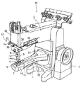
図1は本発明に係る糸切り装置付き三本針筒形タイプのミシン全体の概略斜視図、図2は同ミシンの一部を横断し、要部である糸切り装置付近を中心にした平面図、図3は図2のX−X線での拡大縦断面図である。この三本針筒形タイプのミシンMは、ミシンベッド部2の下方部から前方に向けて、ミシン主軸、針駆動機構や押え駆動機構(これらは周知であるため、詳細な構造及びその説明は省略する)を内蔵するミシンアーム部3とともに筒形ベッド部1が延設されており、この筒形ベッド部1の自由端部上には、ねじ4を介して針板5が固定されているとともに、この針板5下部には、布送り方向(縫製進行方向)aと交差(直交)するb−c方向に往復揺動運動するルーパ6及びルーパ駆動機構(これは周知であるため、詳細な構造及びその説明は省略する)が内装され、かつ、これらルーパ6及びルーパ駆動機構の周囲を包囲するベッド部カバー7が筒形ベッド部1の自由端部にその先端側から着脱可能な状態に設けられている。Hereinafter, embodiments of the present invention will be described with reference to the drawings.
FIG. 1 is a schematic perspective view of an entire three-needle cylinder type sewing machine with a thread trimming device according to the present invention, and FIG. FIGS. 3 and 3 are enlarged longitudinal sectional views taken along line XX in FIG. This three-needle cylinder type sewing machine M has a sewing machine main shaft, a needle drive mechanism and a presser drive mechanism (they are well-known, and the detailed structure and description thereof are directed from the lower part of the
前記ミシンアーム部3の先端部には、上下に往復駆動移動される針棒8及び上下に昇降可能な押え棒9が下方へ突出状態に支持されており、針棒8の下端部には針止め10を介して三本の針11が布送り方向aに対して直交する方向に並列して取付けられているとともに、押え棒9の下端部には針板5に被縫製品を押し付ける押え金12が取付けられている。また、前記針板5は、その左右両側辺5a,5aが布送り方向aに平行に形成されており、この針板5には、筒形ベッド部2の筒軸方向に直交させて三つの針落ち孔13が形成されているとともに、これら針落ち孔13の前後及び左右両側には筒軸方向への布送りを行なう布送り歯(これらは周知のため、省略する)用の溝14が形成され、かつ、針板5の裏面には後述する可動メス15、固定メス16及び糸挟み板17などを主要構成要素とする糸切り装置18が装着されている。 A
図3及び図4〜図6は前記糸切り装置18の具体的な構造を示し、可動メス15は先端部側が鉤状に湾曲しその湾曲先端内周にフック状の糸掛け部15aを有し、かつ、その基端部15bが前記針板5の裏面にねじ軸19を介して止着され、そのねじ軸19を中心にして前記先端のフック状糸掛け部15aが三つの針落ち孔13を横断するように前記ルーパ6の往復揺動運動経路と針板5との間の水平面内を矢印d−e方向に往復揺動可能で、図5及び図6の仮想線に示す退入位置にまで復行揺動されたとき、針板5の布送り方向aに平行な一側辺5aよりも外側方へ突出しない外周縁15cと、図5及び図6の実線に示す進出位置にまで往行揺動されたとき、針板5の布送り用溝14の外側に位置する内周縁15dとを有する形状に構成されている。 3 and 4 to 6 show a specific structure of the
前記ミシンベッド部2の一側部外面には、図2に明示するように、矢印f−g方向に伸縮作動するエアシリンダ20が取付けられ、このエアシリンダ20の可動ロッド21に連結ブロック22、軸23、揺動連結リンク24を介して連動連結されて矢印f−g方向に往復駆動移動される駆動ロッド25が前記筒形ベッド部1内に挿通支持されており、この駆動ロッド25の先端部を前記可動メス15の基端部15b近くに突出させたピン26に嵌合連結することにより、前記可動メス15をエアシリンダ20を介して上述した矢印d−e方向に往復駆動揺動自在に構成している。 As clearly shown in FIG. 2, an
一方、糸切り装置18における固定メス16は、前記可動メス15が図5及び図6の実線に示す進出位置から同図の仮想線に示す退入位置にまで復行揺動するとき、つまり、矢印eからd方向に向けて揺動するとき、その先端のフック状糸掛け部15aに引掛けられて針落ち孔13の側方へ移送される三本の針糸及び一本のルーパ糸を可動メス15との間の剪断作用により切断するものであり、また、糸挟み板17はバネ板27を介して可動メス15下面に弾性的に押圧接触されて該可動メス15の揺動を前記固定メス16との間で弾性的に挟み案内し、かつ、切断後の糸端部を可動メス15の先端部分との間で弾性挟持するものである。 On the other hand, the fixed
上記のような機能を有する固定メス16は、その刃縁16aが、可動メス15との弾性接触点が可動メス15の往復駆動揺動に応じて糸掛け部15a付近の先端部分とその基端部15b寄り部分との間で移り変わりつつ、可動メス15の揺動をその全往復駆動揺動範囲に亘って固定メス16と糸挟み板17との間で挟み案内するように、布送り方向aの前方側ほど布送り歯用の溝14から漸次離れる傾斜方向に沿って斜め直線状に長く形成されているとともに、その斜め直線状の刃縁16aから布送り方向aの後方側に向けて布送り方向aと平行な取付板部16bが一体に形成され、この取付板部16bにおいて固定メス16がねじ部材28を介して針板5の裏面に固定されている。The fixed
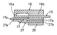
また、前記糸挟み板17は、その遊端縁17aが、可動メス15の全往復駆動揺動範囲に亘って該可動メス15の揺動を前記固定メス16との間で挟み案内するように、前記固定メス16の刃縁16aと略同一平面位置、具体的には、図7に示すように、固定メス16の刃縁16aより僅かに突出した位置で前記傾斜方向に沿って斜め直線状に長く形成されているとともに、その斜め直線状の遊端縁17aから布送り方向aの後方側に向けて布送り方向aと平行な取付板部17bが一体に形成され、この取付板部17bにおいて糸挟み板17が、該糸挟み板17の遊端縁17aを弾性押圧する斜め直線状の遊端縁27aと取付板部17bに重なる取付板部27bとを有して糸挟み板17とほぼ相似形状に形成されているバネ板27、さらには長方形状の押圧板29を重合させた状態でねじ部材30を介して固定メス16の裏面に固定されている。なお、バネ板27の取付板部27bには、糸挟み板17の弾性押圧位置を調整可能な長孔27cが形成されている。また、固定メス16,糸挟み板17,バネ板27,押圧板29が取付けられる針板5の裏面には凹溝5Aが形成されている。Further, the
さらに、三本針筒形タイプのミシンMにおけるミシンアーム部3の先端部位置には、図1に示すように、三本の針11に向けて供給される三本の針糸31(図1では図示省略、図8,図9参照)の繰出し供給を規制及び規制解除可能な針糸押え装置32が装備されている。この針糸押え装置32は、図8及び図9に明示するように、ミシンアーム部3先端の面板33にねじ部材34を介してその一端部が固定された針糸押圧板取付台35と、この針糸押圧板取付台35の前部に対向配置され、その中間部が前記面板33にねじ込み固定された頭付きねじ部材36の頭部との間に介在されたバネ37を介してその一端部を支点にして前記針糸押圧板取付台35側に揺動させるように弾性付勢された可動針糸押圧板38と、この可動針糸押圧板38をバネ37の弾性付勢力に抗して前記針糸押圧板取付台35から離れるように駆動揺動させるエアシリンダ39とから構成されている。 Further, as shown in FIG. 1, three needle threads 31 (see FIG. 1) supplied toward the three needles 11 are provided at the position of the tip of the sewing machine arm portion 3 in the three-needle cylinder type sewing machine M. Then, a
そして、この針糸押え装置32は、図10のタイミングチャートでも明らかなように、通常の縫製時には、エアシリンダ39の伸長動作により可動針糸押圧板38が図8に示すごとく針糸押圧板取付台35から離れる方向に駆動揺動されて三本の針糸31の繰出し供給を許容(規制解除)し、縫製終了後の前記糸切り装置18による糸切り動作の開始と同時にエアシリンダ39の収縮動作に伴い可動針糸押圧板38がバネ37の弾性付勢力により図9に示すごとく針糸押圧板取付台35側に揺動されて三本の針糸31を可動針糸押圧板38と針糸押圧板取付台35との間に押圧保持して繰出し供給を規制し、かつ、糸切り装置18による糸切り動作の終了と同時に再びエアシリンダ39の伸長動作により図8に示すごとく三本の針糸31の繰出し供給の規制を解除するように動作する。 As is apparent from the timing chart of FIG. 10, the
次に、上記のように構成された糸切り装置18及び針糸押え装置32を備えた三本針筒形タイプのミシンMによる縫製及び糸切り作用について説明する。 Next, the sewing and thread trimming actions of the three needle cylinder type sewing machine M provided with the
筒形ベッド部1にその自由端部側から挿入された被縫製品の筒状部位は布送り歯を介して所定の布送り方向aに送られながら、例えばカバーリング等の縫製が行われる。そして、所定の縫製が終了した時点で、糸切り装置18の可動メス15は、その先端のフック状糸掛け部15aが針板5における三つの針落ち孔13を横断して図5及び図6の実線に示す進出位置に往行駆動揺動され、続いて、この進出位置から図5及び図6の仮想線に示す退入位置にまで復行駆動揺動される。この復行駆動揺動時に、針落ち孔13を上下方向に通過している三本の針糸31及びルーパ6に係止されているルーパ糸(図示省略する)が前記フック状糸掛け部15aに引掛けられて針落ち孔13及び送り歯用の溝14の一側方へ移送されて可動メス15と固定メス16との間の剪断作用により切断され、かつ、その切断された糸端部は可動メス15の先端部分と糸挟み板17の遊端縁17aとの間に弾性挟持される。 For example, a cover ring or the like is sewn while the cylindrical portion of the sewing product inserted into the cylindrical bed portion 1 from the free end side is fed in a predetermined cloth feeding direction a via the cloth feeding teeth. When the predetermined sewing is completed, the
上記のような可動メス15の進出位置と退入位置との間に亘る全往復駆動揺動範囲において、該可動メス15は固定メス16と糸挟み板17との間で挟み案内されて振らつき等のない状態で一定の水平面に沿ってスムーズかつ安定よく揺動されることになる。ここで本発明では、可動メス15の揺動を挟み案内する固定メス16の刃縁16a及び糸挟み板17の遊端縁17aが、両者(固定メス16及び糸挟み板17)による挟み案内点が可動メス15の往復駆動揺動に応じて、そのフック状糸掛け部15aを含む先端部分とその基端部分間で移り変わるように、布送り方向aの前方側ほど布送り歯用の溝14から漸次離れる傾斜方向に沿って斜め直線状に長く形成されているので、固定メス16及び糸挟み板17の基端部分を針板5の側方部に突出させなくても、可動メス15の挟み案内作用及び糸切り作用を確実に行わせることが可能であり、これら固定メス16及び糸挟み板17を両側辺5a,5aが布送り方向aに平行に形成された糸切り装置を付設していない標準的な針板5の幅内に収めてその裏面に固定することが可能である。これによって、固定メス16及び糸挟み板17の基端部を固定するために特別な取付台の使用は不要で部品点数、組付工数の削減が図れるとともに、筒形ベッド部1の一部に側方への膨出部を形成する必要も全くなく、筒形ベッド部1を可及的に小径化、小型化することが可能であり、その結果、被縫製品の小径筒状部位であっても筒形ベッド部1にそれの自由端側から引っ掛かりなどない状態で容易かつスムーズに挿入して所定の縫製を行なうことができる。In the entire reciprocating drive swing range between the advance position and the retract position of the
また、可動メス15のフック状糸掛け部15aに引掛けられて側方へ移送されてくる三本の針糸31及びルーパ糸を固定メス16の長い刃縁16aに沿って移動させながら切断することが可能であるから、刃縁16aの特定箇所に切断負荷が集中することなく糸切断負荷を刃縁16aに沿って分散することができるので、刃縁16aの損耗(いわゆる、刃こぼれ)や変形による切れ味の低下が抑制され、固定メス16を頻繁に交換するなどの面倒な手間をかけなくても長期間に亘って常に切れ味のよい糸切断機能を確保することができる。 Further, the three
さらに、上記したような針糸押え装置32を設けて、糸切り装置18における可動メス15の先端糸掛け部15aが三本の針糸31及びルーパ糸を引掛けて移送を開始する糸切り動作開始時点からそれら各糸を可動メス15と固定メス16との剪断作用による切断が完了する糸切り動作終了時点までの間、三本の針糸31の繰出し供給を規制することによって、可動メス15の糸掛け部15aに引掛けられて側方に移送され切断された三本の針糸31の切断端部が可動メス15の先端部と糸挟み板17の遊端縁17aとの間に挟持されることを阻止して、それら切断針糸端部を針板5の下方に自由端として垂れ下がった状態とすることが可能であり、これによって、縫製の完了した筒状部位を筒形ベッド部1から抜き出し操作するとき、弾性挟持力による抵抗が働かず、縫製完了した筒状部位を楽に、かつ、スムーズに筒形ベッド部1から抜き出すことができる。 Further, the above-described
なお、上記実施の形態では、三本針筒形タイプのミシンMに適用したものについて詳述したが、二本針筒形タイプのミシンに適用してもよい。 In addition, in the said embodiment, although what was applied to the three needle cylinder type sewing machine M was explained in full detail, you may apply to a two needle cylinder type sewing machine.
また、上記実施の形態では、糸切り装置18のほかに、針糸押え装置32を装備したものについて説明したが、この針糸押え装置32を備えていない場合でも、糸切り装置18によって奏される効果は達成可能である。 Further, in the above-described embodiment, the description has been given of the one equipped with the needle
さらに、上記実施の形態では、前記針糸押え装置32による針糸押え動作の開始時期を糸切り装置18による糸切り動作の開始時期と一致させ、かつ、針糸押え装置32による針糸押え動作の終了時期を糸切り装置18による糸切り動作の終了時期と一致させたもので説明したが、図10の点線で示すように、針糸押え装置32による針糸押え動作の開始時期を糸切り装置18による糸切り動作の開始時期よりも少し前になるように設定し、かつ、針糸押え装置32による針糸押え動作の終了時期を糸切り装置18による糸切り動作の終了時期よりも少し後になるように設定してもよい。 Further, in the above embodiment, the start timing of the needle thread presser operation by the needle
1 筒形ベッド部
5 針板
5a 針板の側辺部
6 ルーパ
11 針
13 針落ち孔
14 送り歯用の溝
15 可動メス
15a フック状糸掛け部
15b 基端部
16 固定メス
16a 刃縁
16b 取付板部
17 糸挟み板
17a 遊端縁
17b 取付板部
18 糸切り装置
19 ねじ軸
28,30 ねじ部材
31 針糸
32 針糸押え装置
a 布送り方向(縫製進行方向)
M 三本針筒形タイプのミシンDESCRIPTION OF SYMBOLS 1
M Three needle cylinder type sewing machine
Claims (4)
前記固定メスは、その刃縁が、可動メスとの弾性接触点が可動メスの往復駆動揺動に応じてその先端糸掛け部分とその基端寄り部分間で移り変わりつつ、可動メスの揺動をその全往復駆動揺動範囲に亘って固定メスと糸挟み板との間で挟み案内するように、布送り方向の前方側ほど布送り用溝から漸次離れる傾斜方向に沿って斜め直線状に長く形成されているとともに、
前記糸挟み板は、その遊端縁が、前記可動メスの全往復駆動揺動範囲に亘って該可動メスの揺動を固定メスとの間で挟み案内するように、前記固定メスの刃縁と略同一平面位置で前記傾斜方向に沿って斜め直線状に長く形成され、
かつ、これら固定メス及び糸挟み板は、布送り方向に平行な両側辺を有する針板の一側辺から外方へ突出しない状態で針板の裏面に固定されていることを特徴とする糸切り装置付きミシン。At the free end of the cylindrical bed, there are a plurality of needle drop holes perpendicular to the cylinder axis direction and grooves for cloth feed teeth that are arranged before and after the needle drop holes and feed the cloth in the cylinder axis direction. A needle plate is fixed, and a looper that reciprocally swings in a direction crossing the cloth feeding direction is provided in a cylindrical bed at the bottom of the needle plate, and the tip side is curved in a bowl shape. A reciprocating swinging motion of the looper having a thread hooking portion on the inner periphery of the tip and so that the tip yarn hooking portion traverses a plurality of needle drop holes around an axis provided on the back side of the needle plate A movable knife that is reciprocally driven and swung in a horizontal plane between the path and the needle plate, and when this movable knife is reciprocally swung, it is hooked on the thread hook and transferred to the side of the needle drop hole. A fixed knife that cuts a plurality of needle threads and looper threads by a shearing action with a movable knife; A thread pinch plate that contacts the knife and elastically holds and guides the swing of the movable knife between the fixed knife and elastically holds the cut thread end portion between the tip of the movable knife; In a sewing machine with a thread trimming device provided with
The fixed knife has its blade edge swinging the movable knife while the elastic contact point with the movable knife changes between the tip threading portion and the proximal end portion according to the reciprocating drive swing of the movable knife. The front side in the cloth feed direction is longer in a slanting straight line along the inclination direction gradually away from the cloth feed groove so as to be pinched and guided between the fixed knife and the thread clamp plate over the entire reciprocating drive swing range. Formed,
The thread clamping plate has a blade edge of the fixed knife so that its free end edge pinches and guides the swing of the movable knife between the movable knife and the fixed knife over the entire reciprocating drive swing range of the movable knife. And is formed in a slanting linear shape along the inclined direction at substantially the same plane position,
In addition, the fixed knife and the thread pinching plate are fixed to the back surface of the needle plate in a state in which they do not protrude outward from one side of the needle plate having both sides parallel to the cloth feeding direction. Sewing machine with cutting device.
Priority Applications (4)
| Application Number | Priority Date | Filing Date | Title |
|---|---|---|---|
| JP2004295431A JP4645886B2 (en) | 2004-09-07 | 2004-09-07 | Sewing machine with thread trimmer |
| TW094129826A TW200632173A (en) | 2004-09-07 | 2005-08-31 | Sewing machine with thread cutter |
| KR1020050082559A KR101090216B1 (en) | 2004-09-07 | 2005-09-06 | Sewing machine having thread cutting device |
| CN2005101037076A CN1746371B (en) | 2004-09-07 | 2005-09-07 | Sewing machine with stitch breaking device |
Applications Claiming Priority (1)
| Application Number | Priority Date | Filing Date | Title |
|---|---|---|---|
| JP2004295431A JP4645886B2 (en) | 2004-09-07 | 2004-09-07 | Sewing machine with thread trimmer |
Publications (2)
| Publication Number | Publication Date |
|---|---|
| JP2006075552A JP2006075552A (en) | 2006-03-23 |
| JP4645886B2 true JP4645886B2 (en) | 2011-03-09 |
Family
ID=36155480
Family Applications (1)
| Application Number | Title | Priority Date | Filing Date |
|---|---|---|---|
| JP2004295431A Active JP4645886B2 (en) | 2004-09-07 | 2004-09-07 | Sewing machine with thread trimmer |
Country Status (4)
| Country | Link |
|---|---|
| JP (1) | JP4645886B2 (en) |
| KR (1) | KR101090216B1 (en) |
| CN (1) | CN1746371B (en) |
| TW (1) | TW200632173A (en) |
Families Citing this family (11)
| Publication number | Priority date | Publication date | Assignee | Title |
|---|---|---|---|---|
| JP4337063B2 (en) * | 2007-02-08 | 2009-09-30 | ヤマトミシン製造株式会社 | Sewing machine with thread trimmer |
| KR200447773Y1 (en) * | 2007-07-10 | 2010-02-17 | 치 시앙 인더스트리얼 캄퍼니 리미티드 | Automatic yarn cutting device of sewing machine |
| JP5557126B2 (en) * | 2007-10-17 | 2014-07-23 | ヤマトミシン製造株式会社 | Sewing machine thread trimmer |
| JP5777035B2 (en) * | 2013-08-08 | 2015-09-09 | ヤマトミシン製造株式会社 | Thread trimming device and thread trimming method for double chain stitch sewing machine |
| JP5850439B2 (en) * | 2013-09-20 | 2016-02-03 | ヤマトミシン製造株式会社 | Double chain stitch method and double chain stitch machine |
| CN107916507B (en) * | 2016-10-08 | 2023-10-31 | 杰克科技股份有限公司 | Thread cutting device of sewing machine |
| CN106436072B (en) * | 2016-11-29 | 2023-07-11 | 浙江中捷缝纫科技有限公司 | Thread cutting mechanism of sewing machine |
| CN110670256A (en) * | 2018-07-02 | 2020-01-10 | 天津宝盈电脑机械有限公司 | Multi-needle chain type transverse sewing machine head |
| CN109797492B (en) * | 2019-02-27 | 2021-04-20 | 杰克缝纫机股份有限公司 | Control method for eliminating stitches on fabric |
| CN112226928B (en) * | 2020-11-11 | 2022-08-16 | 东莞市钰腾机械科技有限公司 | Sew with long stitches cutting device |
| KR102296620B1 (en) | 2021-03-10 | 2021-09-02 | 주식회사 피앤비무역 | Sewing machine and seam method to form a double knot to prevent loosening of seams |
Citations (3)
| Publication number | Priority date | Publication date | Assignee | Title |
|---|---|---|---|---|
| JPS63139879U (en) * | 1987-03-03 | 1988-09-14 | ||
| JPH0179477U (en) * | 1987-11-13 | 1989-05-29 | ||
| JPH05200179A (en) * | 1991-10-24 | 1993-08-10 | Yamato Sewing Mach Seizo Kk | Cutting of thread in sewing machine and its apparatus |
Family Cites Families (3)
| Publication number | Priority date | Publication date | Assignee | Title |
|---|---|---|---|---|
| US5623887A (en) * | 1994-07-29 | 1997-04-29 | Tokai Kogyo Mishin Kabushiki Kaisha | Thread cutting device in sewing machine |
| CN1123855A (en) * | 1994-12-01 | 1996-06-05 | 十木株式会社 | Apparatus for cutting a needle thread of a sewing machine |
| JPH0975575A (en) * | 1995-09-13 | 1997-03-25 | Tokai Ind Sewing Mach Co Ltd | Thread cutting device of sewing machine |
-
2004
- 2004-09-07 JP JP2004295431A patent/JP4645886B2/en active Active
-
2005
- 2005-08-31 TW TW094129826A patent/TW200632173A/en unknown
- 2005-09-06 KR KR1020050082559A patent/KR101090216B1/en active IP Right Grant
- 2005-09-07 CN CN2005101037076A patent/CN1746371B/en not_active Expired - Fee Related
Patent Citations (4)
| Publication number | Priority date | Publication date | Assignee | Title |
|---|---|---|---|---|
| JPS63139879U (en) * | 1987-03-03 | 1988-09-14 | ||
| JPH0718392Y2 (en) * | 1987-03-03 | 1995-05-01 | ペガサスミシン製造株式会社 | Thread cutting device for multi-needle cylinder type sewing machine |
| JPH0179477U (en) * | 1987-11-13 | 1989-05-29 | ||
| JPH05200179A (en) * | 1991-10-24 | 1993-08-10 | Yamato Sewing Mach Seizo Kk | Cutting of thread in sewing machine and its apparatus |
Also Published As
| Publication number | Publication date |
|---|---|
| JP2006075552A (en) | 2006-03-23 |
| KR101090216B1 (en) | 2011-12-06 |
| CN1746371B (en) | 2011-07-27 |
| TWI340189B (en) | 2011-04-11 |
| TW200632173A (en) | 2006-09-16 |
| KR20060051038A (en) | 2006-05-19 |
| CN1746371A (en) | 2006-03-15 |
Similar Documents
| Publication | Publication Date | Title |
|---|---|---|
| KR101090216B1 (en) | Sewing machine having thread cutting device | |
| TWI411716B (en) | Sewing machine yarn breaking device | |
| US8893631B2 (en) | Multi-needle sewing machine | |
| WO2016182088A1 (en) | Thread cutting device for double chainstitch sewing machine | |
| JP4337063B2 (en) | Sewing machine with thread trimmer | |
| JP2006102400A (en) | Sewing machine | |
| KR100871596B1 (en) | Sewing machine with thread cutter | |
| JP2008178455A (en) | Thread cutter of sewing machine | |
| EP2241662B1 (en) | Thread cutting device for sewing machine | |
| JP2010188106A (en) | Thread cutter for button sewing machine | |
| JP2001321589A (en) | Thread cutter for eyelet stitching sewing machine | |
| JP2008220915A (en) | Thread cutter for sewing machine | |
| TW201708650A (en) | Double chainstitch sewing machine equipped with seam fray-stopping device | |
| JPH0734838B2 (en) | Looper sewing machine bobbin thread gripping device | |
| CN110117877A (en) | One kind going to Bird's Nest mechanism | |
| JPH1170281A (en) | Method and device for preventing stitch from being unsewn, for use with double chain stitch sewing machine | |
| JP2010213858A (en) | Sequin feeder | |
| JP5446014B2 (en) | Thread trimmer for sewing machine with button | |
| JP2747765B2 (en) | Sewing machine thread trimming method and apparatus | |
| JP2006271476A (en) | Sewing machine | |
| JP2010057529A (en) | Thread cutting method for single chain stitch sewing machine and device therefor | |
| CN212270402U (en) | Thread passing mechanism of double-needle single-station sewing machine | |
| JP2000312793A (en) | Bobbin thread cutting device of sewing machine | |
| JP2546453B2 (en) | Sewing machine thread holding and holding device | |
| JP2008018023A (en) | Thread cutter of eyelet sewing machine |
Legal Events
| Date | Code | Title | Description |
|---|---|---|---|
| A621 | Written request for application examination |
Free format text: JAPANESE INTERMEDIATE CODE: A621 Effective date: 20070820 |
|
| A977 | Report on retrieval |
Free format text: JAPANESE INTERMEDIATE CODE: A971007 Effective date: 20100122 |
|
| A131 | Notification of reasons for refusal |
Free format text: JAPANESE INTERMEDIATE CODE: A131 Effective date: 20100518 |
|
| A521 | Request for written amendment filed |
Free format text: JAPANESE INTERMEDIATE CODE: A523 Effective date: 20100618 |
|
| TRDD | Decision of grant or rejection written | ||
| A01 | Written decision to grant a patent or to grant a registration (utility model) |
Free format text: JAPANESE INTERMEDIATE CODE: A01 Effective date: 20101026 |
|
| A01 | Written decision to grant a patent or to grant a registration (utility model) |
Free format text: JAPANESE INTERMEDIATE CODE: A01 |
|
| A61 | First payment of annual fees (during grant procedure) |
Free format text: JAPANESE INTERMEDIATE CODE: A61 Effective date: 20101124 |
|
| FPAY | Renewal fee payment (event date is renewal date of database) |
Free format text: PAYMENT UNTIL: 20131217 Year of fee payment: 3 |
|
| R150 | Certificate of patent or registration of utility model |
Ref document number: 4645886 Country of ref document: JP Free format text: JAPANESE INTERMEDIATE CODE: R150 Free format text: JAPANESE INTERMEDIATE CODE: R150 |
|
| R250 | Receipt of annual fees |
Free format text: JAPANESE INTERMEDIATE CODE: R250 |
|
| R250 | Receipt of annual fees |
Free format text: JAPANESE INTERMEDIATE CODE: R250 |
|
| R250 | Receipt of annual fees |
Free format text: JAPANESE INTERMEDIATE CODE: R250 |
|
| R250 | Receipt of annual fees |
Free format text: JAPANESE INTERMEDIATE CODE: R250 |
|
| R250 | Receipt of annual fees |
Free format text: JAPANESE INTERMEDIATE CODE: R250 |
|
| R250 | Receipt of annual fees |
Free format text: JAPANESE INTERMEDIATE CODE: R250 |
|
| R250 | Receipt of annual fees |
Free format text: JAPANESE INTERMEDIATE CODE: R250 |
|
| R250 | Receipt of annual fees |
Free format text: JAPANESE INTERMEDIATE CODE: R250 |
|
| R250 | Receipt of annual fees |
Free format text: JAPANESE INTERMEDIATE CODE: R250 |
|
| R250 | Receipt of annual fees |
Free format text: JAPANESE INTERMEDIATE CODE: R250 |