JP4642100B2 - Heat pump equipment - Google Patents
Heat pump equipment Download PDFInfo
- Publication number
- JP4642100B2 JP4642100B2 JP2008223531A JP2008223531A JP4642100B2 JP 4642100 B2 JP4642100 B2 JP 4642100B2 JP 2008223531 A JP2008223531 A JP 2008223531A JP 2008223531 A JP2008223531 A JP 2008223531A JP 4642100 B2 JP4642100 B2 JP 4642100B2
- Authority
- JP
- Japan
- Prior art keywords
- cop
- heat pump
- time
- compressor
- value
- Prior art date
- Legal status (The legal status is an assumption and is not a legal conclusion. Google has not performed a legal analysis and makes no representation as to the accuracy of the status listed.)
- Active
Links
- 238000010257 thawing Methods 0.000 claims description 82
- 239000003507 refrigerant Substances 0.000 claims description 58
- 238000001514 detection method Methods 0.000 claims description 55
- 230000005494 condensation Effects 0.000 claims description 29
- 238000009833 condensation Methods 0.000 claims description 29
- 238000001704 evaporation Methods 0.000 claims description 26
- 230000008020 evaporation Effects 0.000 claims description 21
- 238000010438 heat treatment Methods 0.000 claims description 15
- 238000005259 measurement Methods 0.000 claims description 4
- 238000012935 Averaging Methods 0.000 claims description 2
- 230000003247 decreasing effect Effects 0.000 claims 1
- 238000000034 method Methods 0.000 description 19
- 230000007423 decrease Effects 0.000 description 14
- 238000010586 diagram Methods 0.000 description 12
- 230000015572 biosynthetic process Effects 0.000 description 5
- 238000005057 refrigeration Methods 0.000 description 5
- 239000012530 fluid Substances 0.000 description 4
- 239000007789 gas Substances 0.000 description 4
- 239000007788 liquid Substances 0.000 description 4
- 239000002826 coolant Substances 0.000 description 3
- 230000006870 function Effects 0.000 description 3
- 238000009423 ventilation Methods 0.000 description 3
- CURLTUGMZLYLDI-UHFFFAOYSA-N Carbon dioxide Chemical compound O=C=O CURLTUGMZLYLDI-UHFFFAOYSA-N 0.000 description 2
- 238000001816 cooling Methods 0.000 description 2
- 239000004215 Carbon black (E152) Substances 0.000 description 1
- ZAMOUSCENKQFHK-UHFFFAOYSA-N Chlorine atom Chemical compound [Cl] ZAMOUSCENKQFHK-UHFFFAOYSA-N 0.000 description 1
- 229910002092 carbon dioxide Inorganic materials 0.000 description 1
- 239000001569 carbon dioxide Substances 0.000 description 1
- 239000000460 chlorine Substances 0.000 description 1
- 229910052801 chlorine Inorganic materials 0.000 description 1
- 230000006835 compression Effects 0.000 description 1
- 238000007906 compression Methods 0.000 description 1
- NBVXSUQYWXRMNV-UHFFFAOYSA-N fluoromethane Chemical compound FC NBVXSUQYWXRMNV-UHFFFAOYSA-N 0.000 description 1
- 239000001307 helium Substances 0.000 description 1
- 229910052734 helium Inorganic materials 0.000 description 1
- SWQJXJOGLNCZEY-UHFFFAOYSA-N helium atom Chemical compound [He] SWQJXJOGLNCZEY-UHFFFAOYSA-N 0.000 description 1
- 229930195733 hydrocarbon Natural products 0.000 description 1
- 150000002430 hydrocarbons Chemical class 0.000 description 1
- 238000002844 melting Methods 0.000 description 1
- 230000008018 melting Effects 0.000 description 1
Images


Classifications
-
- F—MECHANICAL ENGINEERING; LIGHTING; HEATING; WEAPONS; BLASTING
- F25—REFRIGERATION OR COOLING; COMBINED HEATING AND REFRIGERATION SYSTEMS; HEAT PUMP SYSTEMS; MANUFACTURE OR STORAGE OF ICE; LIQUEFACTION SOLIDIFICATION OF GASES
- F25B—REFRIGERATION MACHINES, PLANTS OR SYSTEMS; COMBINED HEATING AND REFRIGERATION SYSTEMS; HEAT PUMP SYSTEMS
- F25B49/00—Arrangement or mounting of control or safety devices
- F25B49/005—Arrangement or mounting of control or safety devices of safety devices
-
- F—MECHANICAL ENGINEERING; LIGHTING; HEATING; WEAPONS; BLASTING
- F25—REFRIGERATION OR COOLING; COMBINED HEATING AND REFRIGERATION SYSTEMS; HEAT PUMP SYSTEMS; MANUFACTURE OR STORAGE OF ICE; LIQUEFACTION SOLIDIFICATION OF GASES
- F25B—REFRIGERATION MACHINES, PLANTS OR SYSTEMS; COMBINED HEATING AND REFRIGERATION SYSTEMS; HEAT PUMP SYSTEMS
- F25B30/00—Heat pumps
- F25B30/02—Heat pumps of the compression type
-
- F—MECHANICAL ENGINEERING; LIGHTING; HEATING; WEAPONS; BLASTING
- F25—REFRIGERATION OR COOLING; COMBINED HEATING AND REFRIGERATION SYSTEMS; HEAT PUMP SYSTEMS; MANUFACTURE OR STORAGE OF ICE; LIQUEFACTION SOLIDIFICATION OF GASES
- F25D—REFRIGERATORS; COLD ROOMS; ICE-BOXES; COOLING OR FREEZING APPARATUS NOT OTHERWISE PROVIDED FOR
- F25D21/00—Defrosting; Preventing frosting; Removing condensed or defrost water
- F25D21/002—Defroster control
- F25D21/006—Defroster control with electronic control circuits
-
- F—MECHANICAL ENGINEERING; LIGHTING; HEATING; WEAPONS; BLASTING
- F25—REFRIGERATION OR COOLING; COMBINED HEATING AND REFRIGERATION SYSTEMS; HEAT PUMP SYSTEMS; MANUFACTURE OR STORAGE OF ICE; LIQUEFACTION SOLIDIFICATION OF GASES
- F25B—REFRIGERATION MACHINES, PLANTS OR SYSTEMS; COMBINED HEATING AND REFRIGERATION SYSTEMS; HEAT PUMP SYSTEMS
- F25B2500/00—Problems to be solved
- F25B2500/19—Calculation of parameters
-
- F—MECHANICAL ENGINEERING; LIGHTING; HEATING; WEAPONS; BLASTING
- F25—REFRIGERATION OR COOLING; COMBINED HEATING AND REFRIGERATION SYSTEMS; HEAT PUMP SYSTEMS; MANUFACTURE OR STORAGE OF ICE; LIQUEFACTION SOLIDIFICATION OF GASES
- F25B—REFRIGERATION MACHINES, PLANTS OR SYSTEMS; COMBINED HEATING AND REFRIGERATION SYSTEMS; HEAT PUMP SYSTEMS
- F25B2600/00—Control issues
- F25B2600/02—Compressor control
- F25B2600/024—Compressor control by controlling the electric parameters, e.g. current or voltage
-
- F—MECHANICAL ENGINEERING; LIGHTING; HEATING; WEAPONS; BLASTING
- F25—REFRIGERATION OR COOLING; COMBINED HEATING AND REFRIGERATION SYSTEMS; HEAT PUMP SYSTEMS; MANUFACTURE OR STORAGE OF ICE; LIQUEFACTION SOLIDIFICATION OF GASES
- F25B—REFRIGERATION MACHINES, PLANTS OR SYSTEMS; COMBINED HEATING AND REFRIGERATION SYSTEMS; HEAT PUMP SYSTEMS
- F25B2700/00—Sensing or detecting of parameters; Sensors therefor
- F25B2700/15—Power, e.g. by voltage or current
- F25B2700/151—Power, e.g. by voltage or current of the compressor motor
-
- F—MECHANICAL ENGINEERING; LIGHTING; HEATING; WEAPONS; BLASTING
- F25—REFRIGERATION OR COOLING; COMBINED HEATING AND REFRIGERATION SYSTEMS; HEAT PUMP SYSTEMS; MANUFACTURE OR STORAGE OF ICE; LIQUEFACTION SOLIDIFICATION OF GASES
- F25B—REFRIGERATION MACHINES, PLANTS OR SYSTEMS; COMBINED HEATING AND REFRIGERATION SYSTEMS; HEAT PUMP SYSTEMS
- F25B2700/00—Sensing or detecting of parameters; Sensors therefor
- F25B2700/21—Temperatures
- F25B2700/2116—Temperatures of a condenser
Landscapes
- Engineering & Computer Science (AREA)
- Physics & Mathematics (AREA)
- Mechanical Engineering (AREA)
- Thermal Sciences (AREA)
- General Engineering & Computer Science (AREA)
- Chemical & Material Sciences (AREA)
- Combustion & Propulsion (AREA)
- Air Conditioning Control Device (AREA)
- Defrosting Systems (AREA)
Description
本発明は、除霜運転が可能なヒートポンプ装置に関し、特に蒸発器への着霜による性能低下を正確に検知し、最適なタイミングで除霜運転を開始させる除霜開始判定制御処理を実行するヒートポンプ装置に関するものである。 The present invention relates to a heat pump device that can perform a defrosting operation, and in particular, a heat pump that accurately detects a performance decrease due to frosting on an evaporator and performs a defrosting start determination control process that starts the defrosting operation at an optimal timing. It relates to the device.
通常、ヒートポンプ装置における蒸発器では、蒸発温度が0℃以下で、かつ、空気の露点温度以下の場合、蒸発器表面に霜が成長する着霜現象が起きる。このような着霜現象が起きると、蒸発器における通風抵抗の増加及び熱抵抗の増加を招くことになり、蒸発器での運転効率が低下してしまうことになる。そこで、ヒートポンプ装置では、圧縮機からの吐出冷媒を蒸発器に導き、蒸発器表面に成長した霜を取り除く除霜運転(デフロスト運転)が必要となってくる。 Usually, in an evaporator in a heat pump apparatus, when the evaporation temperature is 0 ° C. or lower and the dew point temperature of air or lower, a frosting phenomenon occurs in which frost grows on the evaporator surface. When such a frosting phenomenon occurs, an increase in ventilation resistance and an increase in thermal resistance in the evaporator are caused, and the operation efficiency in the evaporator is reduced. Therefore, in the heat pump device, it is necessary to perform a defrosting operation (defrosting operation) that guides refrigerant discharged from the compressor to the evaporator and removes frost that has grown on the surface of the evaporator.
従来から、蒸発器に付着した霜を溶解させる除霜運転を実行できるヒートポンプ装置が存在する。そのようなものとして、「COP(成績係数)の平均値が最大になるように、デフロストの突入タイミングを定めている空気調和機」が提案されている(たとえば、特許文献1参照)。この空気調和機は、暖房運転中に室内熱交温度と室内温度と電流値を用いて平均COPを算出し、今回の平均COPが前回の平均COPよりも小さくなったときにデフロストの開始を指令するものである。 Conventionally, there is a heat pump device capable of performing a defrosting operation for melting frost attached to an evaporator. As such, “an air conditioner in which the defrost entry timing is set so that the average value of COP (coefficient of performance) is maximized” has been proposed (for example, see Patent Document 1). This air conditioner calculates the average COP using the indoor heat exchange temperature, the room temperature, and the current value during the heating operation, and instructs the start of defrost when the current average COP becomes smaller than the previous average COP. To do.
特許文献1に記載の空気調和機においては、室内熱交温度、室内空気温度及び圧縮機入力を用いて平均COPを推算し、平均COPが下がり始めたところで除霜運転を開始するものである。しかしながら、能力を室内熱交温度と室内空気温度との差としているため、着霜につれて室内熱交温度が低下し、かつ、室内空気温度も低下してしまうことになる。そのため、能力一定で圧縮機入力だけが低下し、逆にCOPは上がってしまうという誤判定する可能性がある。
In the air conditioner described in
また、特許文献1に記載の空気調和機においては、除霜開始を判定する際に、除霜運転については考慮されていないか、前回の除霜運転時のCOPを用いるようになっている。除霜運転を考慮していない場合は、除霜運転も含めた1サイクル平均COPが悪くなってしまう可能性がある。前回の除霜運転時のCOPを用いている場合も、前回の除霜運転時のCOPは前回の暖房運転に対するものであり、運転状況及び負荷等が変わっている今回の暖房運転に適用した場合、COPとしては悪くなってしまう可能性がある。
Moreover, in the air conditioner described in
本発明は、上記のような課題を解決するためになされたもので、最も効率がよくなる(COPが最大となる)最適なタイミングで除霜運転開始を可能としたヒートポンプ装置を提供することを目的としている。 The present invention has been made to solve the above-described problems, and an object of the present invention is to provide a heat pump device capable of starting a defrosting operation at an optimal timing with the highest efficiency (maximum COP). It is said.
本発明に係るヒートポンプ装置は、圧縮機、凝縮器、膨張手段、蒸発器が順次接続された冷媒回路を有するヒートポンプ装置であって、前記凝縮器の飽和温度を検出する凝縮温度検出手段と、前記蒸発器の飽和温度を検出する蒸発温度検出手段と、前記凝縮温度検出手段の検出値から推算した暖房能力を前記凝縮温度検出手段の検出値と前記蒸発温度検出手段の検出値の差または前記差から推算した消費電力で除した値により、運転効率を推測する制御部と、を有し、前記制御部は、推測した前記運転効率が、前記運転効率を運転開始から現時点まで平均した値から現時点で除霜運転を行った場合の運転開始から除霜運転終了までの平均運転効率を推算した値まで低下した場合に除霜運転を開始することを特徴とする。 The heat pump device according to the present invention is a heat pump device having a refrigerant circuit in which a compressor, a condenser, an expansion means, and an evaporator are sequentially connected, and a condensation temperature detection means for detecting a saturation temperature of the condenser, The evaporating temperature detecting means for detecting the saturation temperature of the evaporator, and the heating capacity estimated from the detected value of the condensing temperature detecting means is the difference between the detected value of the condensing temperature detecting means and the detected value of the evaporating temperature detecting means or the difference A control unit that estimates the operating efficiency by a value divided by the power consumption estimated from the control unit, and the control unit calculates the estimated operating efficiency from a value obtained by averaging the operating efficiency from the start of operation to the present time. The defrosting operation is started when the average operating efficiency from the start of the operation when the defrosting operation is performed to the end of the defrosting operation is reduced to the estimated value .
本発明に係るヒートポンプ装置は、圧縮機、凝縮器、膨張手段、蒸発器が順次接続された冷媒回路を有するヒートポンプ装置であって、前記凝縮器の飽和温度を検出する凝縮温度検出手段と、前記圧縮機の運転電流を検出する圧縮機運転電流検出手段と、前記凝縮温度検出手段の検出値から推算した暖房能力を前記圧縮機運転電流検出手段の検出値または前記検出値から推算した消費電力で除した値により、運転効率を推測し、推測した前記運転効率が、前記運転効率を運転開始から現時点まで平均した値から現時点で除霜運転を行った場合の運転開始から除霜運転終了までの運転効率を推算した値まで低下した際に除霜運転を開始する制御部と、を有することを特徴とする。 The heat pump device according to the present invention is a heat pump device having a refrigerant circuit in which a compressor, a condenser, an expansion means, and an evaporator are sequentially connected, and a condensation temperature detection means for detecting a saturation temperature of the condenser, Compressor operating current detecting means for detecting the operating current of the compressor, and heating capacity estimated from the detected value of the condensing temperature detecting means by the detected value of the compressor operating current detecting means or the power consumption estimated from the detected value The operation efficiency is estimated by the value obtained by dividing the estimated operation efficiency from the start of operation when the defrost operation is performed at the present time from the average value of the operation efficiency from the start of operation to the present time until the end of the defrost operation. And a control unit that starts the defrosting operation when the operating efficiency is reduced to the estimated value.
本発明に係るヒートポンプ装置によれば、凝縮温度と蒸発温度から暖房COPを正確に推算し、かつ、除霜運転を含めた1サイクル平均COPを推算することにより、1サイクル平均COPが最もよくなる最適なタイミングで除霜運転を開始することが可能となり、省エネとなる。 According to the heat pump device according to the present invention, the optimum one-cycle average COP is obtained by accurately estimating the heating COP from the condensation temperature and the evaporation temperature and estimating the one-cycle average COP including the defrosting operation. It is possible to start the defrosting operation at a proper timing, which saves energy.
本発明に係るヒートポンプ装置によれば、圧縮機の運転電流から暖房COPを正確に推算し、かつ、除霜運転を含めた1サイクル平均COPを推算することにより、1サイクル平均COPが最もよくなる最適なタイミングで除霜運転を開始することが可能となり、省エネとなる。 According to the heat pump device according to the present invention, the optimum one-cycle average COP is obtained by accurately estimating the heating COP from the compressor operating current and estimating the one-cycle average COP including the defrosting operation. It is possible to start the defrosting operation at a proper timing, which saves energy.
以下、本発明の実施の形態を図面に基づいて説明する。
実施の形態1.
図1は、本発明の実施の形態1に係るヒートポンプ装置100の冷媒回路構成を示す概略構成図である。図1に基づいて、ヒートポンプ装置100の冷媒回路構成及び動作について説明する。このヒートポンプ装置100は、冷媒を循環させることで、冷房運転あるいは暖房運転を実行するものである。なお、図1を含め、以下の図面では各構成部材の大きさの関係が実際のものとは異なる場合がある。
Hereinafter, embodiments of the present invention will be described with reference to the drawings.
FIG. 1 is a schematic configuration diagram showing a refrigerant circuit configuration of a
図1に示すように、ヒートポンプ装置100は、圧縮機1と、凝縮器2と、膨張手段3と、蒸発器4と、を冷媒配管15で順次直列に接続して構成されている。また、凝縮器2の近傍には凝縮器用ファン5及び凝縮温度検出手段11が、蒸発器4の近傍には蒸発器用ファン6及び蒸発温度検出手段12が、それぞれ設けられている。さらに、凝縮温度検出手段11及び蒸発温度検出手段12が検出した検出値は、ヒートポンプ装置100の全体を統括制御する制御部50に送られるようになっている。
As shown in FIG. 1, the
圧縮機1は、冷媒配管15を流れる冷媒を吸入し、その冷媒を圧縮して高温・高圧の状態とするものである。凝縮器2は、冷媒配管15を導通する冷媒と空気との間で熱交換を行ない、冷媒を凝縮するものである。膨張手段3は、冷媒配管15を導通する冷媒を減圧して膨張させるものである。この膨張手段3は、たとえば電子膨張弁等で構成するとよい。蒸発器4は、冷媒配管15を導通する冷媒と空気との間で熱交換を行ない、その冷媒を蒸発するものである。凝縮器用ファン5は、凝縮器2に空気を供給するものである。蒸発器用ファン6は、蒸発器4に空気を供給するものである。凝縮温度検出手段11は、凝縮器2の飽和温度を検出するものである。蒸発温度検出手段12は、蒸発器4の飽和温度を検出するものである。
The
制御部50は、マイクロコンピュータ等で構成されており、上述した各検出手段からの検出値(凝縮温度検出手段11で検出された凝縮温度情報、及び、蒸発温度検出手段12で検出された蒸発温度情報)に基づいて圧縮機1の駆動周波数、凝縮器用ファン5及び蒸発器用ファン6の回転数、冷媒の流路切替装置である四方弁(図示省略)の切替、及び、膨張手段3の開度を制御する機能を有している。なお、制御部50については、図2で詳細に説明するものとする。
The
ここで、ヒートポンプ装置100の動作について簡単に説明する。
ヒートポンプ装置100が運転を開始すると、まず圧縮機1が駆動される。そして、圧縮機1で圧縮された高温・高圧のガス冷媒は、圧縮機1から吐出され凝縮器2に流入する。この凝縮器2では、流入したガス冷媒が、流体に放熱しながら凝縮し、低温・高圧の冷媒となる。この冷媒は、凝縮器2から流出し、膨張手段3で減圧され、気液二相冷媒となる。この気液二相冷媒は、蒸発器4に流入する。蒸発器4に流入した冷媒は、流体から吸熱することで、蒸発ガス化する。この冷媒は、蒸発器4から流出し、圧縮機1に再度吸入される。また、ヒートポンプ装置100の運転中、凝縮温度検出手段11及び蒸発温度検出手段12からの検出値が制御部50に送られている。
Here, the operation of the
When the
図2は、ヒートポンプ装置100の電気的な概略構成を示すブロック図である。図2に基づいて、制御部50の機能について詳細に説明する。図2に示すように、制御部50は、メモリ51と、演算部52と、を有している。凝縮温度検出手段11あるいは蒸発温度検出手段12で検出された検出値は、制御部50のメモリ51へ送られ、格納される。メモリ51に格納された検出値は、演算部52によって演算される。つまり、制御部50は、メモリ51及び演算部52での算出結果情報に基づいて、圧縮機1、四方弁(図示省略)、膨張手段3、凝縮器用ファン5、及び、蒸発器用ファン6の各駆動部へ制御信号を送るようになっている。
FIG. 2 is a block diagram showing an electrical schematic configuration of the
この場合、暖房運転時の運転効率を表す瞬間COP=COPを凝縮温度Tc、蒸発温度Teを用いて下記式(1)から推算するものとする。なお、式(1)は、カルノー効率の定義式である。消費電力は、Tc−Teで推算したものである。
式(1)
COP=(Tc+273.15)/(Tc−Te)
In this case, the instantaneous COP = COP representing the operating efficiency during the heating operation is estimated from the following formula (1) using the condensation temperature Tc and the evaporation temperature Te. Equation (1) is a definition equation of Carnot efficiency. The power consumption is estimated by Tc-Te.
Formula (1)
COP = (Tc + 273.15) / (Tc−Te)
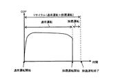
図3は、時間とCOPとの関係を示すグラフである。図3に基づいて、ヒートポンプ装置100の時間とCOPとの関係について説明する。図3では、横軸が時間を、縦軸がCOPをそれぞれ表している。蒸発器4での冷媒と空気との熱交換においては、冷媒の温度が0℃以下で空気の露点温度以下である場合は、空気中に含まれる水分が蒸発器4へ付着し、霜へと成長する着霜現象が発生する。蒸発器4での着霜現象が進むと、通風抵抗の増加及び熱抵抗の増加により、蒸発器4における熱交換量が減少し、図3に示すように瞬間COPが低下するため、除霜運転が必要となってくる。
FIG. 3 is a graph showing the relationship between time and COP. Based on FIG. 3, the relationship between the time of the
式(1)に示した瞬間COP=COPは、着霜とともにTcよりもTeの低下が大きく、着霜による瞬間COPの低下を正確に捉えることができる。たとえば、凝縮温度Tcについては、運転開始時にTc=49℃であったものが除霜開始直前にはTc=47℃となり約2℃低下することになる。それに対し、蒸発温度Teは、運転開始時にTe=−2℃であったものが除霜開始直前にはTe=−6となり約4℃低下し、着霜とともにCOPが低下することになる。 In the instantaneous COP = COP shown in the equation (1), the decrease in Te is larger than Tc together with frost formation, and the decrease in the instantaneous COP due to frost formation can be accurately captured. For example, the condensation temperature Tc, which was Tc = 49 ° C. at the start of operation, becomes Tc = 47 ° C. immediately before the start of defrosting, and is reduced by about 2 ° C. On the other hand, the evaporation temperature Te, which was Te = −2 ° C. at the start of operation, becomes Te = −6 immediately before the start of defrosting and decreases by about 4 ° C., and the COP decreases with frost formation.
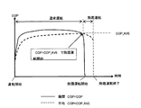
図4は、時間とCOPとの関係を示すグラフである。図4に基づいて、ヒートポンプ装置の1サイクル平均COPについて説明する。除霜運転を伴う運転の場合の運転効率は、図4に示すように通常運転開始から除霜運転終了までを1サイクルとし、その1サイクル平均COPにより評価される。すなわち、1サイクル平均COPが最も高くなるタイミングで除霜運転を開始することが重要となり、このタイミングで除霜運転を開始すれば省エネを効果的に実現できることになる。 FIG. 4 is a graph showing the relationship between time and COP. Based on FIG. 4, the one-cycle average COP of the heat pump apparatus will be described. The operation efficiency in the case of the operation accompanied by the defrosting operation is evaluated by the one-cycle average COP with one cycle from the start of the normal operation to the end of the defrosting operation as shown in FIG. That is, it is important to start the defrosting operation at the timing when the one-cycle average COP becomes the highest, and energy saving can be effectively realized if the defrosting operation is started at this timing.
図5は、ヒートポンプ装置100の除霜開始判定制御に関する処理の流れの一例を示すフローチャートである。図6は、瞬間COPと平均COPとの関係を示すグラフである。図7は、瞬間COPと1サイクル平均COPとの関係を示すグラフである。図8は、瞬間COPと平均COPとの関係を示すグラフである。図9は、ヒートポンプ装置100の除霜開始判定制御に関する処理の流れの他の一例を示すフローチャートである。図5〜図9に基づいて、ヒートポンプ装置100の除霜開始判定制御に関する処理の流れについて説明する。図6〜図8では、横軸が時間を、縦軸がCOPを、それぞれ表している。
FIG. 5 is a flowchart illustrating an example of a process flow relating to the defrosting start determination control of the
ヒートポンプ装置100が運転を開始すると、制御部50は、凝縮温度検出手段11で検出された検出値である凝縮温度Tc、及び、蒸発温度検出手段12で検出された値出値である除霜温度Teから上記式(1)で表される瞬間COP=COPの演算を行なう(ステップS101)。その後、図6に示すように通常運転開始から現時点までの平均COP=COP_AVEを計算する(ステップS102)。図7に示すように1サイクルCOP=COP_CYCLEが最も高くなる除霜開始タイミングは、瞬間COP=COPが着霜により1サイクル平均COP=COP_CYCLEまで低下したときである。
When the
現時点で除霜運転を開始したときの1サイクル平均=COP_CYCLEは、通常運転開始から現時点までの平均COP=COP_AVEを用いて下記式(2)のように表される。
式(2)
COP_CYCLE=C×COP_AVE
One cycle average = COP_CYCLE when the defrosting operation is started at the present time is expressed by the following equation (2) using the average COP = COP_AVE from the start of the normal operation to the current time.
Formula (2)
COP_CYCLE = C × COP_AVE
上記式(2)の右辺におけるCは、図7に示すように除霜運転による平均COPの低下を考慮したものである。このCについては、予め設定されている定数であってもよい。たとえば、除霜により1サイクル平均COPが暖房運転時の平均COP=COP_AVEの96%となる場合は、C=0.96となる。これは、除霜方式、機器のスペックにより最適値は異なるため、その都度最適値に設定してもよい。 C on the right side of the above equation (2) takes into account the decrease in average COP due to the defrosting operation as shown in FIG. This C may be a preset constant. For example, when 1 cycle average COP is 96% of average COP = COP_AVE during heating operation due to defrosting, C = 0.96. Since the optimum value differs depending on the defrosting method and device specifications, the optimum value may be set each time.
現時点で除霜運転を開始した場合の1サイクル平均COPを上記式(2)から算出し、現時点の瞬間COP=COPと比較する(ステップS103)。比較した結果、下記式(3)に示すような関係が成立したら除霜運転を開始する(ステップS103;YES)。一方、下記式(3)が成立していない場合は(ステップS103;NO)、ステップS101に戻り、前記工程を繰り返す。
式(3)
COP=COP_CYCLE
The one-cycle average COP when the defrosting operation is started at the present time is calculated from the above formula (2), and is compared with the current moment COP = COP (step S103). As a result of the comparison, the defrosting operation is started when the relationship shown in the following formula (3) is established (step S103; YES). On the other hand, when the following formula (3) is not satisfied (step S103; NO), the process returns to step S101 and the above steps are repeated.
Formula (3)
COP = COP_CYCLE
ステップS103においては、図8に示すように、現時点の瞬間COPが、1サイクル平均COPではなく現時点までの平均COP=COP_AVEまで低下したときに除霜運転を開始するようにしてもよい。このときのフローチャートは、図9に示す通りで、ステップS203においては、下記式(4)が成立したときに除霜運転を開始することになる。なお、それ以外のステップについては、図5と同様である。
式(4)
COP=COP_AVE
In step S103, as shown in FIG. 8, the defrosting operation may be started when the current instantaneous COP is reduced to the average COP = COP_AVE up to the current time instead of the one-cycle average COP. The flowchart at this time is as shown in FIG. 9, and in step S203, the defrosting operation is started when the following equation (4) is established. The other steps are the same as in FIG.
Formula (4)
COP = COP_AVE
図10は、ヒートポンプ装置100に圧縮機運転時間計測手段13を備えた状態の冷媒回路構成を示す概略構成図である。図11は、ヒートポンプ装置100の瞬間COPと1サイクル平均COPとの関係を示すグラフである。図10及び図11に基づいて、圧縮機1の運転時間がある一定時間を経過した後に除霜開始判定を行なう場合について説明する。図10に示すように、圧縮機1には圧縮機運転時間計測手段13が設けられている。この圧縮機運転時間計測手段13での計測時間は、制御部50に送られるようになっている。
FIG. 10 is a schematic configuration diagram showing a refrigerant circuit configuration in a state in which the
ある一定時間とは、圧縮機1の起動直後は、冷凍サイクルが安定していないため、圧縮機1の起動から冷凍サイクルが十分安定するまでの時間、たとえば20分程度に設定してもよいし、除霜開始判定に問題なければ更に短く設定してもよい。したがって、図10及び図11から、ヒートポンプ装置100は、圧縮機1の駆動時間がある一定時間を経過した後に除霜開始判定を行なうようにしてもよい。なお、ある一定時間は、変更できるようにしておくとよい。
The certain time period may be set to, for example, about 20 minutes from the start of the
たとえば、前回の除霜時間が5分以下であれば、ある一定時間を30分、前回の除霜時間が5分以上であれば、ある一定時間を20分とそれぞれ設定すれば、着霜量により、判定開始時間を変えることができる。 For example, if the previous defrost time is 5 minutes or less, the fixed time is set to 30 minutes, and if the previous defrost time is 5 minutes or more, the fixed time is set to 20 minutes. Thus, the determination start time can be changed.
図12は、ヒートポンプ装置100の瞬間COPと1サイクル平均COPとの関係を示すグラフである。図13は、ヒートポンプ装置100の除霜開始判定制御に関する処理の流れの更に他の一例を示すフローチャートである。図12及び図13に基づいて、瞬間COP=COPが1サイクル平均COP=COP_CYCLEをある一定時間連続して下回った場合に除霜運転を開始する場合の処理の流れについて説明する。図12では、横軸が時間を、縦軸がCOPを、それぞれ表している。なお、図13で特段の説明をしていない部分は、図5で説明した内容と同様である。
FIG. 12 is a graph showing the relationship between the instantaneous COP and the one-cycle average COP of the
ヒートポンプ装置100は、図12に示すように瞬間COP=COPが1サイクル平均COP=COP_CYCLEをある一定時間連続して下回った場合に除霜運転を開始するようにしてもよい。このときのフローチャートは、図13に示すとおりである。ステップS304でタイマTIMERをカウントし、ステップS305でタイマTIMERがある一定時間tを経過したと判定されれば除霜運転を開始する(ステップS305;YES)。一定時間tを経過する前にステップS303の条件を外れた場合は(ステップS303;NO)、タイマTIMERをリセットし、判定をやり直す。このようにすることで、ノイズ等の急激な変化で瞬間COP=COPが1サイクル平均COP=COP_CYCLEを下回った場合に、誤った除霜運転開始を避けることが可能となる。
As shown in FIG. 12, the
図14は、ヒートポンプ装置100のCOPの時間変化量と時間との関係を示すグラフである。図15は、ヒートポンプ装置100の除霜開始判定制御に関する処理の流れの更に他の一例を示すフローチャートである。図14及び図15に基づいて、瞬間COP=COPが1サイクル平均COP=COP_CYCLEを下回り、かつ、瞬間COP=COPのある一定時間内における変化量ΔCOPまたは蒸発温度Teのある一定時間内における変化量ΔTeが予め設定された値Xを一定時間t連続で下回った場合に除霜運転を開始する際の処理の流れについて説明する。図14では、横軸が時間を、縦軸がΔCOPまたはΔTeを、それぞれ表している。なお、図15で特段の説明をしていない部分は、図5で説明した内容と同様である。
FIG. 14 is a graph showing the relationship between the time change amount of COP of the
ヒートポンプ装置100は、瞬間COP=COPが1サイクル平均COP=COP_CYCLEを下回り、かつ、図14に示すように瞬間COP=COPのある一定時間内における変化量ΔCOPまたは蒸発温度Teのある一定時間内における変化量ΔTeが予め設定された値Xを一定時間t連続で下回った場合に除霜運転を開始するようにしてもよい。このときのフローチャートは、図15に示すとおりである。ステップS404でΔCOPまたはΔTeがXを下回ったら(ステップS404;YES)、ステップS405でタイマTIMERのカウントを開始し、ステップS406でタイマTIMERがある一定時間t経過したと判定されれば除霜運転を開始する(ステップS406;YES)。
In the
一定時間t経過する前にステップS403またはステップS404の条件を外れた場合は(ステップS403;NOまたはステップS404;NO)、タイマTIMERをリセットし、判定をやり直す。このようにすることで、ノイズ等の急激な変化や圧縮機周波数変化、負荷変動による一時的なCOP変化で、誤った除霜運転開始を避けることが可能となる。なお、この実施の形態1における凝縮温度検出手段11としては、サーミスタで直接温度を測定する手段でもよいし、圧力センサから凝縮温度を換算する手段でもよいし、その他凝縮温度が推定できる手段でもよい。また、この実施の形態1における蒸発温度検出手段12としては、サーミスタで直接温度を測定する手段でもよいし、圧力センサから蒸発温度を換算する手段でもよいし、その他蒸発温度が推定できる手段でもよい。 If the condition of step S403 or step S404 is not satisfied before the fixed time t has elapsed (step S403; NO or step S404; NO), the timer TIMER is reset and the determination is performed again. By doing so, it becomes possible to avoid erroneous defrosting operation start due to a sudden change such as noise, a change in compressor frequency, and a temporary COP change due to load fluctuation. The condensation temperature detecting means 11 in the first embodiment may be a means for directly measuring the temperature with a thermistor, a means for converting the condensation temperature from a pressure sensor, or a means for estimating the condensation temperature. . Further, the evaporation temperature detecting means 12 in the first embodiment may be a means for directly measuring the temperature with a thermistor, a means for converting the evaporation temperature from a pressure sensor, or another means for estimating the evaporation temperature. .
実施の形態2.
図16は、本発明の実施の形態2に係るヒートポンプ装置100aの冷媒回路構成を示す概略構成図である。図16に基づいて、ヒートポンプ装置100aの冷媒回路構成及び動作について説明する。このヒートポンプ装置100aは、冷媒を循環させることで、冷房運転あるいは暖房運転を実行するものである。なお、この実施の形態2では、実施の形態1と同一部分には同一符号を付し、実施の形態1との相違点を中心に説明するものとする。
FIG. 16 is a schematic configuration diagram showing a refrigerant circuit configuration of a
図16に示すように、ヒートポンプ装置100aは、圧縮機1と、凝縮器2と、膨張手段3と、蒸発器4と、を冷媒配管15で順次直列に接続して構成されている。また、凝縮器2の近傍には凝縮器用ファン5及び凝縮温度検出手段11が、蒸発器4の近傍には蒸発器用ファン6が、圧縮機1には圧縮機1の運転電流を検出する圧縮機運転電流検出手段14が、それぞれ設けられている。さらに、凝縮温度検出手段11及び圧縮機運転電流検出手段14が検出した検出値は、ヒートポンプ装置100の全体を統括制御する制御部50に送られるようになっている。つまり、ヒートポンプ装置100aは、蒸発温度検出手段12が設けられておらず、圧縮機運転電流検出手段14が設けられている点で、ヒートポンプ装置100と相違している。
As shown in FIG. 16, the
ここで、ヒートポンプ装置100aの動作について簡単に説明する。
ヒートポンプ装置100aが運転を開始すると、まず圧縮機1が駆動される。そして、圧縮機1で圧縮された高温・高圧のガス冷媒は、圧縮機1から吐出され凝縮器2に流入する。この凝縮器2では、流入したガス冷媒が、流体に放熱しながら凝縮し、低温・高圧の冷媒となる。この冷媒は、凝縮器2から流出し、膨張手段3で減圧され、気液二相冷媒となる。この気液二相冷媒は、蒸発器4に流入する。蒸発器4に流入した冷媒は、流体から吸熱することで、蒸発ガス化する。この冷媒は、蒸発器4から流出し、圧縮機1に再度吸入される。また、ヒートポンプ装置100の運転中、凝縮温度検出手段11及び圧縮機運転電流検出手段14からの検出値が制御部50に送られている。
Here, operation | movement of the
When the
図17は、ヒートポンプ装置100aの電気的な概略構成を示すブロック図である。図17に基づいて、制御部50の機能について詳細に説明する。図17に示すように、制御部50は、メモリ51と、演算部52と、を有している。凝縮温度検出手段11あるいは圧縮機運転電流検出手段14で検出された検出値は、制御部50のメモリ51へ送られ、格納される。メモリ51に格納された検出値は、演算部52によって演算される。つまり、制御部50は、メモリ51及び演算部52での算出結果情報に基づいて、圧縮機1、四方弁(図示省略)、膨張手段3、凝縮器用ファン5、及び、蒸発器用ファン6の各駆動部へ制御信号を送るようになっている。
FIG. 17 is a block diagram showing a schematic electrical configuration of the
この場合、暖房運転時の運転効率を表すCOPを凝縮温度Tc、圧縮機運転電流Acを用いて下記式(5)から推算するものとする。消費電力は、Acで推算したものである。
式(5)
COP=(Tc+273.15)/Ac
In this case, COP representing the operation efficiency during the heating operation is estimated from the following equation (5) using the condensation temperature Tc and the compressor operation current Ac. The power consumption is estimated by Ac.
Formula (5)
COP = (Tc + 273.15) / Ac
上述したように、蒸発器4での冷媒と空気との熱交換においては、冷媒の温度が0℃以下で空気の露点温度以下である場合は、空気中に含まれる水分が蒸発器4へ付着し、霜へと成長する着霜現象が発生する。蒸発器4での着霜現象が進むと、通風抵抗の増加及び熱抵抗の増加により、蒸発器4における熱交換量が減少し、図3に示したようにCOPが低下するため、除霜運転が必要となってくる。除霜運転を伴う運転の場合のCOPは、図4に示したように通常運転開始から除霜運転終了までを1サイクルとし、その1サイクル平均COPにより評価される。すなわち、1サイクル平均COPが最も高くなるタイミングで除霜運転を開始することが重要となり、このタイミングで除霜運転を開始すれば省エネを効果的に実現できることになる。 As described above, in the heat exchange between the refrigerant and the air in the evaporator 4, when the temperature of the refrigerant is 0 ° C. or less and the air dew point temperature or less, moisture contained in the air adheres to the evaporator 4. Then, a frosting phenomenon that grows into frost occurs. As the frosting phenomenon in the evaporator 4 proceeds, the amount of heat exchange in the evaporator 4 decreases due to an increase in ventilation resistance and an increase in thermal resistance, and the COP decreases as shown in FIG. Will be needed. The COP in the case of the operation accompanied by the defrosting operation is evaluated by the one-cycle average COP with one cycle from the start of the normal operation to the end of the defrosting operation as shown in FIG. That is, it is important to start the defrosting operation at the timing when the one-cycle average COP becomes the highest, and energy saving can be effectively realized if the defrosting operation is started at this timing.
図18は、ヒートポンプ装置100aの除霜開始判定制御に関する処理の流れの一例を示すフローチャートである。図18に基づいて、ヒートポンプ装置100aの除霜開始判定制御に関する処理の流れについて説明する。ヒートポンプ装置100aが運転を開始すると、制御部50は、凝縮温度検出手段11で検出された検出値である凝縮温度Tc、及び、圧縮機運転電流検出手段14で検出された値出値である圧縮機運転電流Acから上記式(5)で表される瞬間COP=COPの演算を行なう(ステップS501)。
FIG. 18 is a flowchart illustrating an example of a flow of processing relating to defrosting start determination control of the
その後、図6に示したように通常運転開始から現時点までの平均COP=COP_AVEを計算する(ステップS502)。図7に示したように1サイクルCOP=COP_CYCLEが最も高くなる除霜開始タイミングは、瞬間COP=COPが着霜により1サイクル平均COP=COP_CYCLEまで低下したときである。現時点で除霜運転を開始したときの1サイクル平均=COP_CYCLEは、通常運転開始から現時点までの平均COP=COP_AVEを用いて下記式(6)のように表される。
式(6)
COP_CYCLE=C×COP_AVE
Thereafter, as shown in FIG. 6, an average COP = COP_AVE from the start of normal operation to the present time is calculated (step S502). As shown in FIG. 7, the defrosting start timing at which one cycle COP = COP_CYCLE becomes highest is when the instantaneous COP = COP decreases to one cycle average COP = COP_CYCLE due to frost formation. One cycle average = COP_CYCLE when the defrosting operation is started at the present time is expressed by the following equation (6) using the average COP = COP_AVE from the start of the normal operation to the current time.
Formula (6)
COP_CYCLE = C × COP_AVE
上記式(6)の右辺におけるCは、図7に示したように除霜運転による平均COPの低下を考慮したものである。このCについては、予め設定されている定数であってもよい。たとえば、除霜により1サイクル平均COPが暖房運転時の平均COP=COP_AVEの96%となる場合は、C=0.96となる。これは、除霜方式、機器のスペックにより最適値は異なるため、その都度最適値に設定してもよい。 C on the right side of the above formula (6) takes into account the decrease in average COP due to the defrosting operation as shown in FIG. This C may be a preset constant. For example, when 1 cycle average COP is 96% of average COP = COP_AVE during heating operation due to defrosting, C = 0.96. Since the optimum value differs depending on the defrosting method and device specifications, the optimum value may be set each time.
現時点で除霜運転を開始した場合の1サイクル平均COPを上記式(6)から算出し、現時点の瞬間COP=COPと比較する(ステップS503)。比較した結果、下記式(7)に示すような関係が成立したら除霜運転を開始する(ステップS503;YES)。一方、下記式(7)が成立していない場合は(ステップS503;NO)、ステップS501に戻り、前記工程を繰り返す。
式(7)
COP=COP_CYCLE
The one-cycle average COP when the defrosting operation is started at the present time is calculated from the above equation (6), and is compared with the current moment COP = COP (step S503). As a result of the comparison, the defrosting operation is started when the relationship shown in the following formula (7) is established (step S503; YES). On the other hand, when the following formula (7) is not satisfied (step S503; NO), the process returns to step S501 and the above steps are repeated.
Formula (7)
COP = COP_CYCLE
図19は、ヒートポンプ装置100aに圧縮機運転時間計測手段13を備えた状態の冷媒回路構成を示す概略構成図である。図20は、ヒートポンプ装置100aの瞬間COPと1サイクル平均COPとの関係を示すグラフである。図19及び図20に基づいて、圧縮機1の運転時間がある一定時間を経過した後に除霜開始判定を行なう場合について説明する。図19に示すように、圧縮機1には圧縮機運転時間計測手段13が設けられている。この圧縮機運転時間計測手段13での計測時間は、制御部50に送られるようになっている。
FIG. 19 is a schematic configuration diagram showing a refrigerant circuit configuration in a state where the compressor operating time measuring means 13 is provided in the
ある一定時間とは、圧縮機1の起動直後は、冷凍サイクルが安定していないため、圧縮機1の起動から冷凍サイクルが十分安定するまでの時間、たとえば20分程度に設定してもよいし、除霜開始判定に問題なければ更に短く設定してもよい。したがって、図10及び図11から、ヒートポンプ装置100は、圧縮機1の駆動時間がある一定時間を経過した後に除霜開始判定を行なうようにしてもよい。なお、ある一定時間は、変更できるようにしておくとよい。
The certain time period may be set to, for example, about 20 minutes from the start of the
図21は、ヒートポンプ装置100aの瞬間COPと1サイクル平均COPとの関係を示すグラフである。図22は、ヒートポンプ装置100aの除霜開始判定制御に関する処理の流れの他の一例を示すフローチャートである。図21及び図22に基づいて、瞬間COP=COPが1サイクル平均COP=COP_CYCLEをある一定時間連続して下回った場合に除霜運転を開始する場合の処理の流れについて説明する。図21では、横軸が時間を、縦軸がCOPを、それぞれ表している。なお、図22で特段の説明をしていない部分は、図18で説明した内容と同様である。
FIG. 21 is a graph showing the relationship between the instantaneous COP and the one-cycle average COP of the
ヒートポンプ装置100aは、図21に示すように瞬間COP=COPが1サイクル平均COP=COP_CYCLEをある一定時間連続して下回った場合に除霜運転を開始するようにしてもよい。このときのフローチャートは、図22に示すとおりである。ステップS604でタイマTIMERをカウントし、ステップS605でタイマTIMERがある一定時間tを経過したと判定されれば除霜運転を開始する(ステップS605;YES)。一定時間tを経過する前にステップS603の条件を外れた場合は(ステップS603;NO)、タイマTIMERをリセットし、判定をやり直す。このようにすることで、ノイズ等の急激な変化で瞬間COP=COPが1サイクル平均COP=COP_CYCLEを下回った場合に、誤った除霜運転開始を避けることが可能となる。
The
図23は、ヒートポンプ装置100aのCOPの時間変化量と時間との関係を示すグラフである。図24は、ヒートポンプ装置100aの除霜開始判定制御に関する処理の流れの更に他の一例を示すフローチャートである。図23及び図24に基づいて、瞬間COP=COPが1サイクル平均COP=COP_CYCLEを下回り、かつ、瞬間COP=COPのある一定時間内における変化量ΔCOPが予め設定された値Xを一定時間t連続で下回った場合に除霜運転を開始する際の処理の流れについて説明する。図23では、横軸が時間を、縦軸がΔCOPを、それぞれ表している。なお、図24で特段の説明をしていない部分は、図18で説明した内容と同様である。
FIG. 23 is a graph showing the relationship between the amount of time change of COP and the time of the
ヒートポンプ装置100aは、瞬間COP=COPが1サイクル平均COP=COP_CYCLEを下回り、かつ、図23に示すように瞬間COP=COPのある一定時間内における変化量ΔCOPが予め設定された値Xを一定時間t連続で下回った場合に除霜運転を開始するようにしてもよい。このときのフローチャートは、図24に示すとおりである。ステップS704でΔCOPがXを下回ったら(ステップS704;YES)、ステップS705でタイマTIMERのカウントを開始し、ステップS706でタイマTIMERがある一定時間t経過したと判定されれば除霜運転を開始する(ステップS706;YES)。
In the
一定時間t経過する前にステップS703またはステップS704の条件を外れた場合は(ステップS703;NOまたはステップS704;NO)、タイマTIMERをリセットし、判定をやり直す。このようにすることで、ノイズ等の急激な変化や圧縮機周波数変化、負荷変動による一時的なCOP変化で、誤った除霜運転開始を避けることが可能となる。なお、この実施の形態2における凝縮温度検出手段11としては、サーミスタで直接温度を測定する手段でもよいし、圧力センサから凝縮温度を換算する手段でもよいし、その他凝縮温度が推定できる手段でもよい。 If the condition of step S703 or step S704 is not met before the fixed time t has elapsed (step S703; NO or step S704; NO), the timer TIMER is reset and the determination is repeated. By doing so, it becomes possible to avoid erroneous defrosting operation start due to a sudden change such as noise, a change in compressor frequency, and a temporary COP change due to load fluctuation. The condensing temperature detecting means 11 in the second embodiment may be a means for directly measuring the temperature with a thermistor, a means for converting the condensing temperature from a pressure sensor, or a means for estimating the condensing temperature. .
実施の形態1及び実施の形態2では、冷凍サイクル内を循環する冷媒の種類を説明していないが、冷媒の種類を特に限定するものではなく、たとえば二酸化炭素や炭化水素、ヘリウム等のような自然冷媒、HFC410AやHFC407C等の代替冷媒のような塩素を含まない冷媒、もしくは既存の製品に使用されているR22やR134a等のフロン系冷媒のいずれでもよい。また、圧縮機1は、レシプロ、ロータリー、スクロール、あるいは、スクリュー等の各種タイプのいずれのものを用いてもよく、回転数可変可能のものでもよく、回転数固定のものでもよい。
In
1 圧縮機、2 凝縮器、3 膨張手段、4 蒸発器、5 凝縮器用ファン、6 蒸発器用ファン、11 凝縮温度検出手段、12 蒸発温度検出手段、13 圧縮機運転時間計測手段、14 圧縮機運転電流検出手段、15 冷媒配管、50 制御部、51 メモリ、52 演算部、100 ヒートポンプ装置、100a ヒートポンプ装置。
DESCRIPTION OF
Claims (7)
前記凝縮器の飽和温度を検出する凝縮温度検出手段と、
前記蒸発器の飽和温度を検出する蒸発温度検出手段と、
前記凝縮温度検出手段の検出値から推算した暖房能力を前記凝縮温度検出手段の検出値と前記蒸発温度検出手段の検出値の差または前記差から推算した消費電力で除した値により、運転効率を推測する制御部と、を有し、
前記制御部は、
推測した前記運転効率が、前記運転効率を運転開始から現時点まで平均した値から現時点で除霜運転を行った場合の運転開始から除霜運転終了までの平均運転効率を推算した値まで低下した場合に除霜運転を開始する
ことを特徴とするヒートポンプ装置。 A heat pump device having a refrigerant circuit in which a compressor, a condenser, expansion means, and an evaporator are sequentially connected,
Condensation temperature detection means for detecting the saturation temperature of the condenser;
Evaporating temperature detecting means for detecting a saturation temperature of the evaporator;
The operating efficiency is calculated by dividing the heating capacity estimated from the detection value of the condensation temperature detection means by the difference between the detection value of the condensation temperature detection means and the detection value of the evaporation temperature detection means or the power consumption estimated from the difference. A control unit for inferring,
The controller is
When the estimated operating efficiency is reduced from a value obtained by averaging the operating efficiency from the start of operation to the present time to a value obtained by calculating an average operating efficiency from the start of operation when the defrost operation is performed at the present time to the end of the defrost operation. A heat pump device characterized by starting a defrosting operation .
前記凝縮器の飽和温度を検出する凝縮温度検出手段と、
前記圧縮機の運転電流を検出する圧縮機運転電流検出手段と、
前記凝縮温度検出手段の検出値から推算した暖房能力を前記圧縮機運転電流検出手段の検出値または前記検出値から推算した消費電力で除した値により、運転効率を推測し、推測した前記運転効率が、前記運転効率を運転開始から現時点まで平均した値から現時点で除霜運転を行った場合の運転開始から除霜運転終了までの運転効率を推算した値まで低下した際に除霜運転を開始する制御部と、を有する
ことを特徴とするヒートポンプ装置。 A heat pump device having a refrigerant circuit in which a compressor, a condenser, expansion means, and an evaporator are sequentially connected,
Condensation temperature detection means for detecting the saturation temperature of the condenser;
Compressor operating current detecting means for detecting the operating current of the compressor;
The heating efficiency estimated from the detection value of the condensing temperature detection means is estimated by the value obtained by dividing the detection value of the compressor operating current detection means or the power consumption estimated from the detection value, and the estimated operating efficiency However, the defrosting operation is started when the operation efficiency is reduced from the average value from the start of operation to the present time to the value calculated from the start of operation when the defrost operation is performed to the end of the defrost operation. A heat pump device, characterized by comprising:
前記制御部は、
前記圧縮機運転時間計測手段の検出時間が所定の時間以上となった場合に前記請求項1又は2に記載の態様に行い、除霜運転を開始する
ことを特徴とする請求項1又は2に記載のヒートポンプ装置。 Compressor operating time measuring means for measuring the compressor operating time,
The controller is
The detection time of compressor operation time measurement means performs to the embodiment described above in claim 1 or 2 in the case where a predetermined time or more, in claim 1 or 2, characterized in that to start the defrosting operation The heat pump apparatus as described.
前記所定の時間は、
前記除霜運転時間に基づいて決定される
ことを特徴とする請求項3に記載のヒートポンプ装置。 In the operation after the defrosting operation is started and ended,
The predetermined time is
The heat pump device according to claim 3 , wherein the heat pump device is determined based on the defrosting operation time.
推測した前記運転効率が所定の値まで低下した場合で、かつ、前記運転効率が所定の値を一定時間連続で下回った場合に除霜運転を開始する
ことを特徴とする請求項1〜4のいずれか一項に記載のヒートポンプ装置。 The controller is
If guessed the operation efficiency is decreased to a predetermined value, and, of claims 1 to 4, wherein the operating efficiency is characterized in that to start the defrosting operation when it falls below a constant time-continuous a predetermined value The heat pump device according to any one of the above.
前記運転効率が所定の値を下回った場合で、かつ、前記運転効率の一定時間内における変化量が予め設定された値を一定時間連続で下回った場合に除霜運転を開始する
ことを特徴とする請求項1〜4のいずれか一項に記載のヒートポンプ装置。 The controller is
The defrosting operation is started when the operation efficiency falls below a predetermined value and when the amount of change in the operation efficiency within a certain time falls below a preset value continuously for a certain time. The heat pump device according to any one of claims 1 to 4 .
前記運転効率が所定の値を下回った場合で、かつ、前記蒸発温度の一定時間内における変化量が予め設定された値を一定時間連続で下回った場合に除霜運転を開始する
ことを特徴とする請求項1〜4のいずれか一項に記載のヒートポンプ装置。 The controller is
The defrosting operation is started when the operation efficiency falls below a predetermined value and when the amount of change in the evaporation temperature within a certain time falls below a preset value continuously for a certain time. The heat pump device according to any one of claims 1 to 4 .
Priority Applications (6)
| Application Number | Priority Date | Filing Date | Title |
|---|---|---|---|
| JP2008223531A JP4642100B2 (en) | 2008-09-01 | 2008-09-01 | Heat pump equipment |
| EP09809630.8A EP2320168B1 (en) | 2008-09-01 | 2009-03-05 | Heat pump device |
| US13/057,362 US8745999B2 (en) | 2008-09-01 | 2009-03-05 | Heat pump apparatus |
| PCT/JP2009/054147 WO2010023975A1 (en) | 2008-09-01 | 2009-03-05 | Heat pump device |
| CN2009801337522A CN102138048B (en) | 2008-09-01 | 2009-03-05 | Heat pump device |
| EP15150355.4A EP2918954B1 (en) | 2008-09-01 | 2009-03-05 | Heat pump apparatus |
Applications Claiming Priority (1)
| Application Number | Priority Date | Filing Date | Title |
|---|---|---|---|
| JP2008223531A JP4642100B2 (en) | 2008-09-01 | 2008-09-01 | Heat pump equipment |
Publications (2)
| Publication Number | Publication Date |
|---|---|
| JP2010060150A JP2010060150A (en) | 2010-03-18 |
| JP4642100B2 true JP4642100B2 (en) | 2011-03-02 |
Family
ID=41721155
Family Applications (1)
| Application Number | Title | Priority Date | Filing Date |
|---|---|---|---|
| JP2008223531A Active JP4642100B2 (en) | 2008-09-01 | 2008-09-01 | Heat pump equipment |
Country Status (5)
| Country | Link |
|---|---|
| US (1) | US8745999B2 (en) |
| EP (2) | EP2918954B1 (en) |
| JP (1) | JP4642100B2 (en) |
| CN (1) | CN102138048B (en) |
| WO (1) | WO2010023975A1 (en) |
Families Citing this family (22)
| Publication number | Priority date | Publication date | Assignee | Title |
|---|---|---|---|---|
| WO2012003202A2 (en) * | 2010-07-01 | 2012-01-05 | Carrier Corporation | Evaporator refrigerant saturation demand defrost |
| EP2786081A1 (en) * | 2011-12-02 | 2014-10-08 | Kysor Panel Systems Division of Welbilt Walk-Ins, LP | Refrigeration apparatus and method |
| JP5575191B2 (en) * | 2012-08-06 | 2014-08-20 | 三菱電機株式会社 | Dual refrigeration equipment |
| DE102012109198B4 (en) * | 2012-09-27 | 2020-03-26 | ait-deutschland GmbH | Process for controlling the defrosting of a refrigerant evaporator |
| GB2528213B (en) * | 2013-04-18 | 2020-01-15 | Mitsubishi Electric Corp | Heat pump apparatus and air conditioning system |
| JP5981396B2 (en) * | 2013-07-10 | 2016-08-31 | サンポット株式会社 | Heat pump heat source machine |
| JP5981395B2 (en) * | 2013-07-10 | 2016-08-31 | サンポット株式会社 | Heat pump heat source machine |
| US10816249B2 (en) * | 2015-05-07 | 2020-10-27 | Lennox Industries Inc. | Compressor protection and control in HVAC systems |
| EP3222939B1 (en) * | 2016-03-23 | 2020-08-19 | Honeywell spol s.r.o. | Frost management of an evaporator |
| CN106524420B (en) * | 2016-11-25 | 2019-03-15 | 重庆美的通用制冷设备有限公司 | A kind of air conditioner and its Defrost method and defroster |
| US10458688B2 (en) | 2017-03-22 | 2019-10-29 | Honeywell International Inc. | Frost management of an evaporator |
| US10345038B2 (en) * | 2017-04-25 | 2019-07-09 | Emerson Climate Technologies Retail Solutions, Inc. | Dynamic coefficient of performance calculation for refrigeration systems |
| CN107575998A (en) * | 2017-09-08 | 2018-01-12 | 青岛海尔空调器有限总公司 | The defrosting control method of air-conditioning and its outdoor unit |
| US10488099B2 (en) | 2018-02-22 | 2019-11-26 | Schneider Electric USA, Inc. | Frost detection in HVACandR systems |
| CN108692426B (en) * | 2018-06-01 | 2021-04-20 | 青岛海尔空调器有限总公司 | Defrosting control method for air conditioner |
| CN108592297B (en) * | 2018-06-01 | 2021-04-20 | 青岛海尔空调器有限总公司 | Defrosting control method for air conditioner |
| US11131497B2 (en) * | 2019-06-18 | 2021-09-28 | Honeywell International Inc. | Method and system for controlling the defrost cycle of a vapor compression system for increased energy efficiency |
| EP3800410A1 (en) * | 2019-10-01 | 2021-04-07 | Siemens Schweiz AG | Optimum operation of a heat exchanger |
| CN111271823B (en) * | 2019-12-18 | 2021-06-04 | 宁波奥克斯电气股份有限公司 | Control method for preventing defrosting liquid return of air conditioner and air conditioner |
| CN113137708A (en) * | 2021-03-09 | 2021-07-20 | 青岛海尔空调电子有限公司 | Defrosting control method of air conditioning system, storage medium and air conditioning system |
| CN113739460B (en) * | 2021-08-26 | 2022-06-07 | 珠海格力电器股份有限公司 | Evaporator defrosting treatment method and device and heat pump equipment |
| CN116263263A (en) * | 2021-12-13 | 2023-06-16 | 开利公司 | Method for changing defrosting trigger of heat pump |
Citations (3)
| Publication number | Priority date | Publication date | Assignee | Title |
|---|---|---|---|---|
| JP2002130876A (en) * | 2000-10-18 | 2002-05-09 | Saginomiya Seisakusho Inc | Controller for air conditioner |
| JP2007225158A (en) * | 2006-02-21 | 2007-09-06 | Mitsubishi Electric Corp | Defrosting operation control device and method |
| JP2008145002A (en) * | 2006-12-07 | 2008-06-26 | Sanyo Electric Co Ltd | Air conditioning device |
Family Cites Families (19)
| Publication number | Priority date | Publication date | Assignee | Title |
|---|---|---|---|---|
| JPS5139702B2 (en) * | 1973-11-05 | 1976-10-29 | ||
| US4165036A (en) * | 1977-08-29 | 1979-08-21 | Milton Meckler | Multi source heat pump air conditioning system |
| JPS60133249A (en) * | 1983-12-20 | 1985-07-16 | Matsushita Electric Ind Co Ltd | Defrosting-controlling method for air conditioner |
| DE3404327A1 (en) * | 1984-02-08 | 1985-08-08 | Martin 7120 Bietigheim-Bissingen Lang | Process for controlling the defrosting of evaporators of heat pumps |
| JPS60187851U (en) * | 1984-05-21 | 1985-12-12 | ダイキン工業株式会社 | Defrost control circuit |
| JPS61110848A (en) * | 1984-11-05 | 1986-05-29 | 松下電器産業株式会社 | Defrostation controller for heat pump type air conditioner |
| JPS62218749A (en) * | 1986-03-19 | 1987-09-26 | Matsushita Electric Ind Co Ltd | Defrosting controller for air-conditioning machine |
| JPH01147245A (en) * | 1987-12-02 | 1989-06-08 | Saginomiya Seisakusho Inc | Frost elimination operation control device |
| US4873649A (en) * | 1988-06-10 | 1989-10-10 | Honeywell Inc. | Method for operating variable speed heat pumps and air conditioners |
| US4918942A (en) * | 1989-10-11 | 1990-04-24 | General Electric Company | Refrigeration system with dual evaporators and suction line heating |
| JP3562114B2 (en) * | 1996-03-19 | 2004-09-08 | 株式会社日立製作所 | Air conditioner |
| JPH10111050A (en) * | 1996-10-08 | 1998-04-28 | Daikin Ind Ltd | Air conditioner |
| JPH10318613A (en) * | 1997-05-16 | 1998-12-04 | Hitachi Ltd | Freezing device |
| CN2357287Y (en) * | 1998-11-20 | 2000-01-05 | 海尔集团公司 | Defroster using high-temp high-pressure refrigerator |
| CN2374784Y (en) * | 1999-03-29 | 2000-04-19 | 广东美的集团股份有限公司 | Heat pump air conditioner |
| CN1116558C (en) * | 2000-02-03 | 2003-07-30 | 清华泰豪科技股份有限公司 | Defrost control method of air-cooled heat-pump air-conditioner and its device |
| US6606870B2 (en) * | 2001-01-05 | 2003-08-19 | General Electric Company | Deterministic refrigerator defrost method and apparatus |
| US6701725B2 (en) * | 2001-05-11 | 2004-03-09 | Field Diagnostic Services, Inc. | Estimating operating parameters of vapor compression cycle equipment |
| JP2005188760A (en) | 2003-12-24 | 2005-07-14 | Matsushita Electric Ind Co Ltd | Air conditioner |
-
2008
- 2008-09-01 JP JP2008223531A patent/JP4642100B2/en active Active
-
2009
- 2009-03-05 EP EP15150355.4A patent/EP2918954B1/en active Active
- 2009-03-05 US US13/057,362 patent/US8745999B2/en active Active
- 2009-03-05 WO PCT/JP2009/054147 patent/WO2010023975A1/en active Application Filing
- 2009-03-05 EP EP09809630.8A patent/EP2320168B1/en active Active
- 2009-03-05 CN CN2009801337522A patent/CN102138048B/en active Active
Patent Citations (3)
| Publication number | Priority date | Publication date | Assignee | Title |
|---|---|---|---|---|
| JP2002130876A (en) * | 2000-10-18 | 2002-05-09 | Saginomiya Seisakusho Inc | Controller for air conditioner |
| JP2007225158A (en) * | 2006-02-21 | 2007-09-06 | Mitsubishi Electric Corp | Defrosting operation control device and method |
| JP2008145002A (en) * | 2006-12-07 | 2008-06-26 | Sanyo Electric Co Ltd | Air conditioning device |
Also Published As
| Publication number | Publication date |
|---|---|
| EP2918954B1 (en) | 2021-09-22 |
| EP2320168B1 (en) | 2019-10-09 |
| US8745999B2 (en) | 2014-06-10 |
| JP2010060150A (en) | 2010-03-18 |
| CN102138048B (en) | 2013-05-15 |
| EP2320168A4 (en) | 2015-03-11 |
| CN102138048A (en) | 2011-07-27 |
| EP2918954A1 (en) | 2015-09-16 |
| WO2010023975A1 (en) | 2010-03-04 |
| US20110132019A1 (en) | 2011-06-09 |
| EP2320168A1 (en) | 2011-05-11 |
Similar Documents
| Publication | Publication Date | Title |
|---|---|---|
| JP4642100B2 (en) | Heat pump equipment | |
| JP5092829B2 (en) | Air conditioner | |
| JP6072901B2 (en) | Heat pump device and air conditioning system | |
| JP5511761B2 (en) | Air conditioner | |
| JP6843227B2 (en) | Dehumidifier | |
| JP4767199B2 (en) | Air conditioning system operation control method and air conditioning system | |
| CN111684218B (en) | HVAC system and method of operating a vapor compression system | |
| JP5094801B2 (en) | Refrigeration cycle apparatus and air conditioner | |
| JP2010223494A (en) | Air conditioner | |
| CN109253524B (en) | Control method of heat pump system, heat pump system and air conditioner | |
| JP5988698B2 (en) | Dual refrigeration equipment | |
| JP2019163869A (en) | Cooling device and control method therefor,and control program | |
| JP5366764B2 (en) | Cooling device and refrigeration cycle device | |
| JP2010025374A (en) | Refrigerating device | |
| CN115095956B (en) | Air conditioner and defrosting control method thereof | |
| JP2011149611A (en) | Air-conditioning apparatus | |
| JP5061661B2 (en) | Refrigeration equipment | |
| WO2015114774A1 (en) | Refrigeration cycle device, air conditioning device, and method for calculating circulation composition in refrigeration cycle device | |
| JP6271011B2 (en) | Refrigeration air conditioner | |
| CN117396713B (en) | Refrigerant leak detection system | |
| JP6779361B2 (en) | Air conditioner | |
| JP2000104975A (en) | Air conditioner | |
| JP2020148438A (en) | Refrigeration cycle device |
Legal Events
| Date | Code | Title | Description |
|---|---|---|---|
| A131 | Notification of reasons for refusal |
Free format text: JAPANESE INTERMEDIATE CODE: A131 Effective date: 20100601 |
|
| A521 | Request for written amendment filed |
Free format text: JAPANESE INTERMEDIATE CODE: A523 Effective date: 20100630 |
|
| TRDD | Decision of grant or rejection written | ||
| A01 | Written decision to grant a patent or to grant a registration (utility model) |
Free format text: JAPANESE INTERMEDIATE CODE: A01 Effective date: 20101102 |
|
| A01 | Written decision to grant a patent or to grant a registration (utility model) |
Free format text: JAPANESE INTERMEDIATE CODE: A01 |
|
| A61 | First payment of annual fees (during grant procedure) |
Free format text: JAPANESE INTERMEDIATE CODE: A61 Effective date: 20101130 |
|
| R150 | Certificate of patent or registration of utility model |
Ref document number: 4642100 Country of ref document: JP Free format text: JAPANESE INTERMEDIATE CODE: R150 Free format text: JAPANESE INTERMEDIATE CODE: R150 |
|
| FPAY | Renewal fee payment (event date is renewal date of database) |
Free format text: PAYMENT UNTIL: 20131210 Year of fee payment: 3 |
|
| R250 | Receipt of annual fees |
Free format text: JAPANESE INTERMEDIATE CODE: R250 |
|
| R250 | Receipt of annual fees |
Free format text: JAPANESE INTERMEDIATE CODE: R250 |
|
| R250 | Receipt of annual fees |
Free format text: JAPANESE INTERMEDIATE CODE: R250 |
|
| R250 | Receipt of annual fees |
Free format text: JAPANESE INTERMEDIATE CODE: R250 |
|
| R250 | Receipt of annual fees |
Free format text: JAPANESE INTERMEDIATE CODE: R250 |
|
| R250 | Receipt of annual fees |
Free format text: JAPANESE INTERMEDIATE CODE: R250 |
|
| R250 | Receipt of annual fees |
Free format text: JAPANESE INTERMEDIATE CODE: R250 |
|
| R250 | Receipt of annual fees |
Free format text: JAPANESE INTERMEDIATE CODE: R250 |
|
| R250 | Receipt of annual fees |
Free format text: JAPANESE INTERMEDIATE CODE: R250 |