JP4637882B2 - Conduit device - Google Patents
Conduit device Download PDFInfo
- Publication number
- JP4637882B2 JP4637882B2 JP2007193610A JP2007193610A JP4637882B2 JP 4637882 B2 JP4637882 B2 JP 4637882B2 JP 2007193610 A JP2007193610 A JP 2007193610A JP 2007193610 A JP2007193610 A JP 2007193610A JP 4637882 B2 JP4637882 B2 JP 4637882B2
- Authority
- JP
- Japan
- Prior art keywords
- tube
- quartz
- outer tube
- heating
- heating element
- Prior art date
- Legal status (The legal status is an assumption and is not a legal conclusion. Google has not performed a legal analysis and makes no representation as to the accuracy of the status listed.)
- Expired - Fee Related
Links
Images


Landscapes
- Resistance Heating (AREA)
- Instantaneous Water Boilers, Portable Hot-Water Supply Apparatuses, And Control Of Portable Hot-Water Supply Apparatuses (AREA)
Description
本発明は、加熱管を収容する導管装置に関し、特に、石英内管と石英外管とを設置することにより、石英内管と石英外管との間に熱エネルギーが快速に伝導可能である導管装置に関するものである。 The present invention relates to a conduit device that accommodates a heating tube, and in particular, by installing a quartz inner tube and a quartz outer tube, a conduit that can conduct heat energy quickly between the quartz inner tube and the quartz outer tube. It relates to the device.
従来の市販している加熱装置の加熱管3は、図10に示すように、外部に金属管31を採用し、前記金属管31の内部に発熱体32を設置して、前記発熱体32の末端に電源と連接するための電極棒33を接続して、前記金属管31の内部に絶縁土34が充填して、金属管31をローリングすることにより、充填された絶縁土34を更に緊密にして、樹脂35にて金属管31の末端を密封し、これにより、金属管31が密封状態になる。
As shown in FIG. 10, the
しかしながら、従来の加熱装置によれば、金属管31が水と長時期に接触すると錆び易く、金属管31は爆裂して電流が漏れ出してしまう危険性がある。
また、水中に鉱物質が大量に含んであり、長時期に使用すると、金属管31の外周面に炭酸塩やゴミなどが付着され、これにより、加熱管3に電流を流して発生される熱は水に良く熱伝導できなくなり、熱伝導効率は良くない欠点があった。
However, according to the conventional heating device, when the
In addition, a large amount of mineral is contained in the water, and when used for a long period of time, carbonate or dust adheres to the outer peripheral surface of the
本発明の主な目的は、石英内管と石英外管とを設置することにより、石英内管と石英外管との間に熱エネルギーが快速に伝導可能である導管装置を提供することにある。 A main object of the present invention is to provide a conduit device in which thermal energy can be quickly conducted between a quartz inner tube and a quartz outer tube by installing a quartz inner tube and a quartz outer tube. .
上記目的を達成するためになされた本願の第1発明は、加熱管と外管組とを含み、前記加熱管は、内部に高インピーダンスワイヤが巻き付けられた発熱体が設けてあり、外部に石英内管が嵌め設けてあり、前記発熱体が電極棒と電気的に連接してあり、前記外管組は、前記加熱管を収容する石英外管を有し、前記石英外管の管体には、導入口と導出口とが一組以上設けてあり、前記石英内管と前記石英外管とは、その間に熱伝導空間が形成され、且つその開口端に絶縁具が結合してあり、前記加熱管の電極棒の末端が絶縁具を挿通して外部に突出して電源と接続してあることを特徴とする、導管装置であることを要旨としている。 The first invention of the present application made to achieve the above object includes a heating tube and an outer tube set, and the heating tube is provided with a heating element around which a high-impedance wire is wound. An inner tube is fitted, the heating element is electrically connected to the electrode rod, and the outer tube set includes a quartz outer tube that houses the heating tube, and the quartz outer tube has a tubular body. Is provided with at least one set of inlet and outlet, and the quartz inner tube and the quartz outer tube are formed with a heat conduction space between them, and an insulator is coupled to the opening end thereof, The gist of the present invention is a conduit device characterized in that the end of the electrode rod of the heating tube is inserted through an insulator and protrudes outside to be connected to a power source.
本願の第2発明では、加熱管と外管組と外マスクとを含み、前記加熱管は、内部に高インピーダンスワイヤが巻き付けられた発熱体が設けてあり、外部に石英内管が嵌め設けてあり、前記発熱体が電極棒と電気的に連接してあり、
前記外管組は、前記加熱管を収容する石英外管を有し、前記石英外管の管体には、導入口と導出口とが一組以上設けてあり、前記石英内管と前記石英外管とは、その間に熱伝導空間が形成され、且つその開口端に絶縁具が結合してあり、前記加熱管の電極棒の末端が絶縁具を挿通して外部に突出して電源と接続してあり、前記外マスクは、前記外管組の前記石英外管の外周面を覆い、且つ前記石英外管との間には熱流動空間が形成され、その両端が絶縁具とそれぞれ結合し、その壁面には入り口と出口とが一組以上設けてあることを特徴とする、導管装置であることを要旨としている。
The second invention of the present application includes a heating tube, an outer tube set, and an outer mask, and the heating tube is provided with a heating element around which a high impedance wire is wound, and a quartz inner tube is fitted on the outside. The heating element is electrically connected to the electrode rod;
The outer tube set includes a quartz outer tube that accommodates the heating tube, and the tube body of the quartz outer tube includes one or more inlets and outlets, and the quartz inner tube and the quartz tube The outer tube has a heat conduction space formed between them, and an insulator is coupled to the open end of the outer tube, and the end of the electrode rod of the heating tube passes through the insulator and protrudes to the outside to be connected to the power source. The outer mask covers an outer peripheral surface of the quartz outer tube of the outer tube set, and a heat flow space is formed between the outer tube and the quartz outer tube, and both ends thereof are coupled to an insulator, The gist of the present invention is a conduit device characterized in that one or more inlets and outlets are provided on the wall surface.
本発明の導管装置によれば、次のような効果がある。
(イ)加熱管からの熱エネルギーおよび輻射熱が媒体を加熱して、媒体によって熱伝導を施すことができる。
The conduit device of the present invention has the following effects.
(A) Heat energy and radiant heat from the heating tube heat the medium, and heat conduction can be performed by the medium.
(ロ)石英管の熱伝導特性および透明度が優れるので、発熱体からの熱エネルギーが石英内管と石英外管との間にある熱伝導空間に伝導され、輻射熱が透明な石英管を介して外部に出射され、媒体を快速に高温にすることができる。 (B) Since the heat conduction characteristics and transparency of the quartz tube are excellent, the heat energy from the heating element is conducted to the heat conduction space between the quartz inner tube and the quartz outer tube, and the radiant heat passes through the transparent quartz tube. It is emitted to the outside, and the medium can be rapidly heated to a high temperature.
(ハ)加熱管からの熱エネルギーおよび輻射熱は、石英内管と石英外管との間にある熱伝導空間、又は外マスクの熱流動空間を経由して媒体を快速に加熱することができ、熱伝導を快速に完成可能である。 (C) The heat energy and radiant heat from the heating tube can heat the medium quickly through the heat conduction space between the quartz inner tube and the quartz outer tube, or the heat flow space of the outer mask, Heat conduction can be completed quickly.
(二)管内の高温媒体と低温媒体との熱対流により、熱エネルギーが快速に伝導される。 (2) Thermal energy is rapidly conducted by thermal convection between the hot medium and the cold medium in the pipe.
(ホ)管内の高温による蒸気、高温媒体と圧力変化により、熱対流が渦方式で施すので、熱伝導を快速に完成可能である。 (E) Since heat convection is performed in a vortex manner due to steam, high temperature medium and pressure change due to high temperature in the pipe, heat conduction can be completed quickly.
(へ)加熱管の発熱体からの熱エネルギーおよび輻射熱と、石英外管に開設された複数の導入口および導出口と、外マスクに媒体を導入しているときに形成される渦方式の熱対流とにより、媒体は急速に高温になって蒸気状態になることができる。
(F) Heat energy and radiant heat from the heating element of the heating tube, multiple inlets and outlets established in the quartz outer tube, and vortex heat generated when the medium is introduced into the outer mask By convection, the medium can quickly become hot and become vapor.
以下、添付図面を参照して本発明の好適な実施の形態を詳細に説明する。 Preferred embodiments of the present invention will be described below in detail with reference to the accompanying drawings.
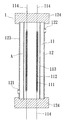
まず、図1を参照する。本発明の導管装置1は、加熱管11と、外管組12と、を含む。
First, refer to FIG. The
前記加熱管11は、内部に高インピーダンスワイヤ112が巻き付けられた発熱体111が設けてあり、外部に石英内管113が嵌め設けてあり、前記発熱体111が電極棒114と電気的に連接してある。
The
前記外管組12は、前記加熱管11を収容する石英外管123を有し、前記石英外管123の管体には、導入口121と導出口122とが設けてあり、前記石英内管113と前記石英外管123とは、その間に熱伝導空間Aが形成され、且つその開口端に絶縁具124が結合してあり、前記加熱管11の電極棒114の末端が絶縁具124を挿通して外部に突出して電源と接続する。
The
また、図2を参照しながら本発明の組付方法を詳細に説明する。前記加熱管11内の発熱体111の外周面に高インピーダンスワイヤ112が巻き付けてあり、且つ発熱体111の末端に電極棒114が連接してあり、そして必要な熱エネを見て発熱体111の本数を増減して、これらの発熱体111を石英内管113に嵌め込むと加熱管11が形成され、また、前記加熱管11を石英外管123に嵌め込んで、前記加熱管11の電極棒114を石英外管123の両端に設けられた絶縁具124(例えばセラミック製でもいい)に挿通して外部に突出して電源と連接し、そうすると、石英外管123と、加熱管11の石英内管113との間には熱伝導空間Aが形成される。
The assembly method of the present invention will be described in detail with reference to FIG. A
また、図1乃至図3を参照しながら本発明の使用状態を詳細に説明する。まず、発熱体111の電極棒114の末端に電流を流して、加熱管11を加熱して、発熱体111からの熱エネおよび輻射熱が石英内管113の壁体を経由して外側に放出され、このとき、石英外管123の導入口121に適当な媒体を導入して、前記媒体が石英外管123と石英内管113との間の熱伝導空間Aに流入され、熱伝導空間Aにおいて、前記媒体が熱エネおよび輻射熱に加熱されて急速に高温になって蒸気状態になり、発生された蒸気が石英外管123に開設された導出口122から排出され、これにより、前記蒸気により熱が必要な箇所まで持たされ、なお、加熱管11を加熱している過程中には、媒体が石英外管123の導入口121から徐々に導入される。
The use state of the present invention will be described in detail with reference to FIGS. First, an electric current is supplied to the end of the
また、図4と図5を参照する。本発明の導管装置1の石英外管123にある導入口121および導出口122とは、必要の熱エネ量を見て一組以上設けてよく、発熱体111からの熱エネおよび輻射熱が石英外管123と、石英内管113との間にある熱伝導空間Aに伝導されることにより、媒体が瞬間に沸き可能の高温になり、これにより、加熱管11からの熱エネは、石英外管123に開設された導入口121および導出口122によって輸送可能である。
Reference is also made to FIGS. One or
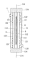
また、図6乃至図9を参照する。本発明の導管装置1は、加熱管11と、外管組12と、外マスク13と、を含む。
Reference is also made to FIGS. The
前記加熱管11は、内部に高インピーダンスワイヤ112が巻き付けられた発熱体111が設けてあり、外部に石英内管113が嵌め設けてあり、前記発熱体111が電極棒114と電気的に連接してある。
The
前記外管組12は、前記加熱管11を収容する石英外管123を有し、前記石英外管123の管体には、導入口121と導出口122とが設けてあり、前記石英内管113と前記石英外管123とは、その間に熱伝導空間Aが形成され、且つその開口端に絶縁具124が結合してあり、前記加熱管11の電極棒114の末端が絶縁具124を挿通して外部に突出して電源と接続する。
The
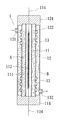
前記外マスク13は、前記外管組12の前記石英外管123の外周面を覆い、且つ前記石英外管123との間には熱流動空間Bが形成され、その両端が絶縁具124とそれぞれ結合し、その壁面には入り口131と出口132とが設けてある。
The
また、上記の実施例の使用状態を詳細に説明する。まず、発熱体111の電極棒114の末端に電流を流して、加熱管11を加熱して、発熱体111からの熱エネおよび輻射熱が石英内管113の壁体を経由して外側に放出され発熱体111からの熱エネおよび輻射熱が透明な石英内管113と石英外管123とを経由しているときに、熱伝導空間A内の媒体が高温になって蒸気状態になり、また、外マスク13の入り口131から媒体を導入することにより、媒体が外マスク13と、石英内管113と石英外管123との間にある熱流動空間Bとに流入され、このとき、石英外管123に開設された複数の導入口121および導出口122に渦方式のサイクルが形成され、これにより、導入される媒体が本来の媒体と混合するようになり、そして発熱体111からの熱エネおよび輻射熱によって媒体が加熱されて急速に高温になって蒸気状態になり、その後、発熱体111を続けて発熱し、且つ外マスク13から媒体を続けて導入し、上記と同様のように、石英外管123に開設された複数の導入口121および導出口122に渦方式のサイクルが形成され、これにより、導入される媒体が本来の媒体と混合するようになり、媒体が加熱されて急速に高温になることができる。
The use state of the above embodiment will be described in detail. First, an electric current is supplied to the end of the
1 導管装置 3 加熱管
11 加熱管 12 外管組
13 外マスク 31 金属管
32 発熱体 33 電極棒
34 絶縁土 35 樹脂
111 発熱体 112 高インピーダンスワイヤ
113 石英内管 114 電極棒
121 導入口 122 導出口
123 石英外管 124 絶縁具
131 入り口 132 出口
A 熱伝導空間 B 熱流動空間
DESCRIPTION OF
Claims (2)
前記加熱管は、内部に高インピーダンスワイヤが巻き付けられた発熱体が設けてあり、外部に石英内管が嵌め設けてあり、前記発熱体が電極棒と電気的に連接してあり、
前記外管組は、前記加熱管を収容する石英外管を有し、前記石英外管の管体には、導入口と導出口とが一組以上設けてあり、前記石英内管と前記石英外管とは、その間に熱伝導空間が形成され、且つその開口端に絶縁具が結合してあり、前記加熱管の電極棒の末端が絶縁具を挿通して外部に突出して電源と接続してあることを特徴とする、
導管装置。 Including a heating tube and an outer tube assembly,
The heating tube is provided with a heating element in which a high impedance wire is wound inside, a quartz inner tube is fitted on the outside, and the heating element is electrically connected to an electrode rod,
The outer tube set includes a quartz outer tube that accommodates the heating tube, and the tube body of the quartz outer tube includes one or more inlets and outlets, and the quartz inner tube and the quartz tube The outer tube has a heat conduction space formed between them, and an insulator is coupled to the open end of the outer tube, and the end of the electrode rod of the heating tube passes through the insulator and protrudes to the outside to be connected to the power source. It is characterized by
Conduit equipment.
前記加熱管は、内部に高インピーダンスワイヤが巻き付けられた発熱体が設けてあり、外部に石英内管が嵌め設けてあり、前記発熱体が電極棒と電気的に連接してあり、
前記外管組は、前記加熱管を収容する石英外管を有し、前記石英外管の管体には、導入口と導出口とが一組以上設けてあり、前記石英内管と前記石英外管とは、その間に熱伝導空間が形成され、且つその開口端に絶縁具が結合してあり、前記加熱管の電極棒の末端が絶縁具を挿通して外部に突出して電源と接続してあり、
前記外マスクは、前記外管組の前記石英外管の外周面を覆い、且つ前記石英外管との間には熱流動空間が形成され、その両端が絶縁具とそれぞれ結合し、その壁面には入り口と出口とが一組以上設けてあることを特徴とする、
導管装置。 Including a heating tube, an outer tube set and an outer mask,
The heating tube is provided with a heating element in which a high impedance wire is wound inside, a quartz inner tube is fitted on the outside, and the heating element is electrically connected to an electrode rod,
The outer tube set includes a quartz outer tube that accommodates the heating tube, and the tube body of the quartz outer tube includes one or more inlets and outlets, and the quartz inner tube and the quartz tube The outer tube has a heat conduction space formed between them, and an insulator is coupled to the open end of the outer tube, and the end of the electrode rod of the heating tube passes through the insulator and protrudes to the outside to be connected to the power source. And
The outer mask covers an outer peripheral surface of the quartz outer tube of the outer tube set, and a heat flow space is formed between the outer mask and the quartz outer tube. Is characterized by having one or more entrances and exits,
Conduit equipment.
Priority Applications (1)
| Application Number | Priority Date | Filing Date | Title |
|---|---|---|---|
| JP2007193610A JP4637882B2 (en) | 2007-07-25 | 2007-07-25 | Conduit device |
Applications Claiming Priority (1)
| Application Number | Priority Date | Filing Date | Title |
|---|---|---|---|
| JP2007193610A JP4637882B2 (en) | 2007-07-25 | 2007-07-25 | Conduit device |
Publications (2)
| Publication Number | Publication Date |
|---|---|
| JP2009030843A JP2009030843A (en) | 2009-02-12 |
| JP4637882B2 true JP4637882B2 (en) | 2011-02-23 |
Family
ID=40401551
Family Applications (1)
| Application Number | Title | Priority Date | Filing Date |
|---|---|---|---|
| JP2007193610A Expired - Fee Related JP4637882B2 (en) | 2007-07-25 | 2007-07-25 | Conduit device |
Country Status (1)
| Country | Link |
|---|---|
| JP (1) | JP4637882B2 (en) |
Families Citing this family (3)
| Publication number | Priority date | Publication date | Assignee | Title |
|---|---|---|---|---|
| JP5538100B2 (en) * | 2010-07-02 | 2014-07-02 | 株式会社アイテック | Heating device |
| CN104713219B (en) * | 2015-01-22 | 2018-07-06 | 浙江万佳热电器科技有限公司 | A kind of instant heating type heating of small size is precious |
| CN108887752A (en) * | 2018-09-17 | 2018-11-27 | 苏州晶品新材料股份有限公司 | Calandria and atomising device and electronic cigarette |
Citations (6)
| Publication number | Priority date | Publication date | Assignee | Title |
|---|---|---|---|---|
| JPH04117345U (en) * | 1991-02-08 | 1992-10-21 | 株式会社小松製作所 | fluid heater |
| JPH0636287U (en) * | 1992-10-09 | 1994-05-13 | 株式会社河合電器製作所 | Electric heater |
| JP2583159B2 (en) * | 1991-02-08 | 1997-02-19 | 株式会社小松製作所 | Fluid heater |
| JP2000227253A (en) * | 1999-02-04 | 2000-08-15 | Nichias Corp | Fluid heater |
| JP2006153419A (en) * | 2004-10-26 | 2006-06-15 | Nippon Pillar Packing Co Ltd | Fluid heater and fluid heating apparatus |
| JP2007101048A (en) * | 2005-10-04 | 2007-04-19 | Shinnetsu Kogyo Kk | Gas heater |
Family Cites Families (5)
| Publication number | Priority date | Publication date | Assignee | Title |
|---|---|---|---|---|
| JPS5120902Y2 (en) * | 1971-07-05 | 1976-05-31 | ||
| JPS5620745Y2 (en) * | 1976-06-17 | 1981-05-16 | ||
| JPS549436A (en) * | 1977-06-21 | 1979-01-24 | Takayoshi Tanigawa | Joint for culvert |
| JPH06331214A (en) * | 1993-05-22 | 1994-11-29 | Metokoiru Kk | Liquid heating method and device thereof |
| JPH10259955A (en) * | 1997-03-19 | 1998-09-29 | Komatsu Ltd | Liquid temperature control device |
-
2007
- 2007-07-25 JP JP2007193610A patent/JP4637882B2/en not_active Expired - Fee Related
Patent Citations (6)
| Publication number | Priority date | Publication date | Assignee | Title |
|---|---|---|---|---|
| JPH04117345U (en) * | 1991-02-08 | 1992-10-21 | 株式会社小松製作所 | fluid heater |
| JP2583159B2 (en) * | 1991-02-08 | 1997-02-19 | 株式会社小松製作所 | Fluid heater |
| JPH0636287U (en) * | 1992-10-09 | 1994-05-13 | 株式会社河合電器製作所 | Electric heater |
| JP2000227253A (en) * | 1999-02-04 | 2000-08-15 | Nichias Corp | Fluid heater |
| JP2006153419A (en) * | 2004-10-26 | 2006-06-15 | Nippon Pillar Packing Co Ltd | Fluid heater and fluid heating apparatus |
| JP2007101048A (en) * | 2005-10-04 | 2007-04-19 | Shinnetsu Kogyo Kk | Gas heater |
Also Published As
| Publication number | Publication date |
|---|---|
| JP2009030843A (en) | 2009-02-12 |
Similar Documents
| Publication | Publication Date | Title |
|---|---|---|
| US7668444B2 (en) | Pipe heater encircled conduit device | |
| CN102401461A (en) | Water heating device | |
| US20120080422A1 (en) | Apparatus for making hot water using carbon heater | |
| JP4637882B2 (en) | Conduit device | |
| JP5004001B2 (en) | Superheated steam generator | |
| KR20150028468A (en) | Instantaneous heating apparatus for electricity | |
| JP2009041885A (en) | Fluid heating device | |
| CN105180424A (en) | Corrugated pipe type gas electric heating device | |
| KR101041305B1 (en) | A device to generate heat by induction heating type | |
| KR20060118822A (en) | A water boiler with carbon tube heater which insided screw | |
| KR101623545B1 (en) | Heat transfer pipe | |
| KR20120025150A (en) | Superheated steam generator | |
| CN101592400A (en) | High-temperature air stainless steel tube electric heater | |
| SE1400002A1 (en) | Pressure vessels and ways to heat a gas in a pressure conduit | |
| JP2004069256A (en) | Fluid heater, method of manufacturing the fluid heater, and method of using the fluid heater | |
| CN110081603A (en) | Embedded-type electric speed heat integration module and its manufacturing process | |
| KR100922136B1 (en) | Conduit device encircling pipe heater | |
| CN109429381A (en) | A kind of high thermal conductivity rotatable heater housing | |
| US1494326A (en) | Continuous-flow water heater | |
| JPH07324826A (en) | Vacuum duplex glass tube | |
| CN208012062U (en) | Electromagnetic induction heater | |
| KR20050118634A (en) | Screw instant heating system | |
| KR20110126844A (en) | Apparatus for making hot water using carbon heater | |
| US20150219361A1 (en) | Device for heating and/or vaporizing a fluid such as water | |
| TWI323766B (en) | A conduit apparatus coated over a heating tube |
Legal Events
| Date | Code | Title | Description |
|---|---|---|---|
| A131 | Notification of reasons for refusal |
Free format text: JAPANESE INTERMEDIATE CODE: A131 Effective date: 20100511 |
|
| A601 | Written request for extension of time |
Free format text: JAPANESE INTERMEDIATE CODE: A601 Effective date: 20100805 |
|
| A602 | Written permission of extension of time |
Free format text: JAPANESE INTERMEDIATE CODE: A602 Effective date: 20100810 |
|
| TRDD | Decision of grant or rejection written | ||
| A01 | Written decision to grant a patent or to grant a registration (utility model) |
Free format text: JAPANESE INTERMEDIATE CODE: A01 Effective date: 20101026 |
|
| A01 | Written decision to grant a patent or to grant a registration (utility model) |
Free format text: JAPANESE INTERMEDIATE CODE: A01 |
|
| A61 | First payment of annual fees (during grant procedure) |
Free format text: JAPANESE INTERMEDIATE CODE: A61 Effective date: 20101124 |
|
| FPAY | Renewal fee payment (event date is renewal date of database) |
Free format text: PAYMENT UNTIL: 20131203 Year of fee payment: 3 |
|
| R150 | Certificate of patent or registration of utility model |
Free format text: JAPANESE INTERMEDIATE CODE: R150 |
|
| LAPS | Cancellation because of no payment of annual fees |