JP4636812B2 - Zoom lens - Google Patents
Zoom lens Download PDFInfo
- Publication number
- JP4636812B2 JP4636812B2 JP2004132608A JP2004132608A JP4636812B2 JP 4636812 B2 JP4636812 B2 JP 4636812B2 JP 2004132608 A JP2004132608 A JP 2004132608A JP 2004132608 A JP2004132608 A JP 2004132608A JP 4636812 B2 JP4636812 B2 JP 4636812B2
- Authority
- JP
- Japan
- Prior art keywords
- lens
- lens group
- layer
- object side
- refractive power
- Prior art date
- Legal status (The legal status is an assumption and is not a legal conclusion. Google has not performed a legal analysis and makes no representation as to the accuracy of the status listed.)
- Expired - Fee Related
Links
Images


Classifications
-
- G—PHYSICS
- G02—OPTICS
- G02B—OPTICAL ELEMENTS, SYSTEMS OR APPARATUS
- G02B15/00—Optical objectives with means for varying the magnification
- G02B15/14—Optical objectives with means for varying the magnification by axial movement of one or more lenses or groups of lenses relative to the image plane for continuously varying the equivalent focal length of the objective
- G02B15/144—Optical objectives with means for varying the magnification by axial movement of one or more lenses or groups of lenses relative to the image plane for continuously varying the equivalent focal length of the objective having four groups only
- G02B15/1441—Optical objectives with means for varying the magnification by axial movement of one or more lenses or groups of lenses relative to the image plane for continuously varying the equivalent focal length of the objective having four groups only the first group being positive
- G02B15/144113—Optical objectives with means for varying the magnification by axial movement of one or more lenses or groups of lenses relative to the image plane for continuously varying the equivalent focal length of the objective having four groups only the first group being positive arranged +-++
Landscapes
- Physics & Mathematics (AREA)
- General Physics & Mathematics (AREA)
- Optics & Photonics (AREA)
- Lenses (AREA)
Description
本発明はズームレンズに関し、例えば、銀塩写真用カメラ、デジタルスチルカメラ、ビデオカメラ等の撮影光学系として好適なものである。 The present invention relates to a zoom lens, and is suitable for a photographic optical system such as a silver salt photographic camera, a digital still camera, and a video camera.
デジタルスチルカメラの高画素化が進む中で、高画素の固体撮像素子用の撮影光学系としてのズームレンズには単色収差の補正のみならず、色収差の十分な補正が求められている。特に高ズーム比化(高変倍比化)してズームレンズの望遠側の焦点距離が長くなると、色収差については一次の色消しに加え、二次スペクトルの低減が求められる。 As the number of pixels of a digital still camera is increasing, a zoom lens as a photographing optical system for a solid-state imaging device having a high pixel is required to sufficiently correct chromatic aberration as well as to correct monochromatic aberration. In particular, when the zoom lens has a high zoom ratio (high zoom ratio) and the focal length on the telephoto side of the zoom lens becomes long, the chromatic aberration is required to reduce the secondary spectrum in addition to the primary achromatism.
従来、望遠側の軸上色収差の二次スペクトルを補正するために、異常分散ガラスを用いたズームレンズが数多く知られている。また、高ズーム比に適したズームレンズ構成としては、最も物体側のレンズ群を正の屈折力としたポジティブリード型が挙げられる。 Conventionally, many zoom lenses using anomalous dispersion glass are known for correcting the secondary spectrum of axial chromatic aberration on the telephoto side. As a zoom lens configuration suitable for a high zoom ratio, there is a positive lead type in which the most object side lens unit has a positive refractive power.
例えば、物体側より順に、正、負、正、正の屈折力の4つのレンズ群が配列されたズームレンズに異常分散性を有するガラスを用いた例として、特許文献1〜4等が挙げられる。 For example, Patent Documents 1 to 4 can be cited as examples in which an anomalous dispersion glass is used for a zoom lens in which four lens groups having positive, negative, positive, and positive refractive power are arranged in order from the object side. .
また、異常分散硝材よりも更に色収差補正の効果が大きい回折光学素子をズームレンズに用いたものとして、特許文献5等が挙げられる。 Further, as a zoom lens using a diffractive optical element that has a greater effect of correcting chromatic aberration than an anomalous dispersion glass material, Patent Document 5 can be cited.
また、樹脂にITO微粒子を混合させたレプリカ材料を回折格子に用いることで回折効率を改善することが、特許文献6で提案されている。 Further, Patent Document 6 proposes to improve the diffraction efficiency by using a replica material in which ITO fine particles are mixed in a resin for a diffraction grating.
一方、第1レンズ群に樹脂層で形成される非球面を設けて単色収差の補正を行う例が、特許文献7にて知られている。
回折光学素子をズームレンズに用いると、異常分散硝材よりも大きな色収差補正効果が得られる。しかしながら、回折格子は光線入射角によって回折効率が変化するので、ズーム時に光線入射条件が変化するズームレンズに用いる場合は、回折光学素子を導入する位置が限定されたり、ズーム時に回折効率が落ちてしまったりする可能性があった。 When a diffractive optical element is used for a zoom lens, a chromatic aberration correction effect greater than that of an anomalous dispersion glass material can be obtained. However, since the diffraction efficiency of the diffraction grating changes depending on the light incident angle, the position where the diffractive optical element is introduced is limited or the diffraction efficiency decreases during zoom when used in a zoom lens in which the light incident conditions change during zooming. There was a possibility of being trapped.
また、特許文献7に開示された通常の樹脂材料で非球面を形成した場合には、色収差補正の効果は得られない。 In addition, when an aspherical surface is formed from a normal resin material disclosed in Patent Document 7, the effect of correcting chromatic aberration cannot be obtained.
本発明は、高ズーム比に適したズームタイプであるポジティブリード型のズームレンズにおいて、色収差を大幅に改善することを目的とする。 An object of the present invention is to significantly improve chromatic aberration in a positive lead type zoom lens that is a zoom type suitable for a high zoom ratio.
上記目的を達成するため、本発明の請求項1のズームレンズは、物体側より像側へ順に、正の屈折力の第1レンズ群、負の屈折力の第2レンズ群、正の屈折力の第3レンズ群、正の屈折力の第4レンズ群からなり、ズーミングに際し、前記第1レンズ群は望遠端で広角端よりも物体側に位置するように移動し、前記第2レンズ群は望遠端で広角端よりも像側に位置するように移動し、前記第3レンズ群は望遠端で広角端よりも物体側に位置するように物体側に凸状の軌跡で移動し、前記第4レンズ群は物体側へ凸状の軌跡で移動するズームレンズにおいて、前記レンズ又は層GITのアッベ数をνIT、前記レンズ又は層GITのg線とF線に関する部分分散比をθITとするとき、前記第1レンズ群は、
11<νIT<27
0.2<θIT<0.4
を満足する材料より成るレンズ又は層GITを有し、該レンズ又は層GITは、負の屈折力であって、前記レンズ又は層GITの焦点距離をf1a、前記第1レンズ群の焦点距離をf1、全系の望遠端における焦点距離をftとするとき、
8<|f1a/f1|<60
0.5<f1/ft<0.9
なる条件を満足することを特徴としている。
本発明の請求項4のズームレンズは、物体側より像側へ順に、正の屈折力の第1レンズ群、負の屈折力の第2レンズ群、正の屈折力の第3レンズ群、正の屈折力の第4レンズ群からなり、ズーミングに際し、前記第1レンズ群は望遠端で広角端よりも物体側に位置するように移動し、前記第2レンズ群は望遠端で広角端よりも像側に位置するように移動し、前記第3レンズ群は望遠端で広角端よりも物体側に位置するように物体側に凸状の軌跡で移動し、前記第4レンズ群は物体側へ凸状の軌跡で移動するズームレンズにおいて、前記レンズ又は層GITのアッベ数をνIT、前記レンズ又は層GITのg線とF線に関する部分分散比をθITとするとき、前記第2レンズ群は、
11<νIT<27
0.2<θIT<0.4
を満足する材料より成るレンズ又は層GITを有し、該レンズ又は層GITは、正の屈折力であって、前記レンズ又は層GITの焦点距離をf2a、前記第2レンズ群の焦点距離をf2、全系の望遠端における焦点距離をftとするとき、
12<|f2a/f2|<20
0.10<|f2/ft|<0.20
なる条件を満足することを特徴としている。
本発明の請求項6のズームレンズは、物体側より像側へ順に、正の屈折力の第1レンズ群、負の屈折力の第2レンズ群、正の屈折力の第3レンズ群、正の屈折力の第4レンズ群からなり、ズーミングに際し、前記第1レンズ群は望遠端で広角端よりも物体側に位置するように移動し、前記第2レンズ群は望遠端で広角端よりも像側に位置するように移動し、前記第3レンズ群は望遠端で広角端よりも物体側に位置するように物体側に凸状の軌跡で移動し、前記第4レンズ群は物体側へ凸状の軌跡で移動するズームレンズにおいて、前記レンズ又は層GITのアッベ数をνIT、前記レンズ又は層GITのg線とF線に関する部分分散比をθITとするとき、前記第3レンズ群は、
11<νIT<27
0.2<θIT<0.4
を満足する材料より成るレンズ又は層GITを有し、該レンズ又は層GITは、負の屈折力であって、前記レンズ又は層GITの焦点距離をf3a、前記第3レンズ群の焦点距離をf3、全系の望遠端における焦点距離をftとするとき、
6<|f3a/f3|<30
0.3<f3/ft<0.45
なる条件を満足することを特徴としている。
In order to achieve the above object, a zoom lens according to a first aspect of the present invention includes, in order from the object side to the image side, a first lens group having a positive refractive power, a second lens group having a negative refractive power, and a positive refractive power. The third lens group, and a fourth lens group having a positive refractive power. During zooming, the first lens group moves to the object side from the wide-angle end at the telephoto end, and the second lens group The telephoto end moves so as to be positioned closer to the image side than the wide-angle end, and the third lens group moves along a convex locus toward the object side so as to be positioned closer to the object side than the wide-angle end at the telephoto end. In a zoom lens that moves along a convex locus toward the object side, the four lens group has a Abbe number of the lens or layer GIT as νIT, and a partial dispersion ratio of the lens or layer GIT with respect to g-line and F-line as θIT. The first lens group includes:
11 <νIT <27
0.2 <θIT <0.4
The lens or layer GIT has a negative refractive power, and the focal length of the lens or layer GIT is f1a, and the focal length of the first lens group is f1. When the focal length at the telephoto end of the entire system is ft,
8 <| f1a / f1 | <60
0.5 <f1 / ft <0.9
It is characterized by satisfying the following conditions.
The zoom lens according to a fourth aspect of the present invention includes, in order from the object side to the image side, a first lens group having a positive refractive power, a second lens group having a negative refractive power, a third lens group having a positive refractive power, The first lens unit moves so as to be positioned closer to the object side than the wide-angle end at the telephoto end, and the second lens unit moves from the wide-angle end to the telephoto end during zooming. The third lens group moves along a locus that is convex toward the object side so that the third lens group is located closer to the object side than the wide-angle end at the telephoto end, and the fourth lens group moves toward the object side. In a zoom lens that moves along a convex locus, when the Abbe number of the lens or layer GIT is νIT, and the partial dispersion ratio of the lens or layer GIT with respect to g-line and F-line is θIT, the second lens group is
11 <νIT <27
0.2 <θIT <0.4
The lens or layer GIT is made of a material that satisfies the following conditions. The lens or layer GIT has a positive refractive power, and the focal length of the lens or layer GIT is f2a, and the focal length of the second lens group is f2. When the focal length at the telephoto end of the entire system is ft,
12 <| f2a / f2 | <20
0.10 <| f2 / ft | <0.20
It is characterized by satisfying the following conditions.
The zoom lens according to a sixth aspect of the present invention includes, in order from the object side to the image side, a first lens group having a positive refractive power, a second lens group having a negative refractive power, a third lens group having a positive refractive power, The first lens unit moves so as to be positioned closer to the object side than the wide-angle end at the telephoto end, and the second lens unit moves from the wide-angle end to the telephoto end during zooming. The third lens group moves along a locus that is convex toward the object side so that the third lens group is located closer to the object side than the wide-angle end at the telephoto end, and the fourth lens group moves toward the object side. In a zoom lens that moves along a convex locus, when the Abbe number of the lens or layer GIT is νIT, and the partial dispersion ratio of the lens or layer GIT with respect to g-line and F-line is θIT, the third lens group is:
11 <νIT <27
0.2 <θIT <0.4
The lens or layer GIT is made of a material that satisfies the following conditions. The lens or layer GIT has negative refractive power, and the focal length of the lens or layer GIT is f3a, and the focal length of the third lens group is f3. When the focal length at the telephoto end of the entire system is ft,
6 <| f3a / f3 | <30
0.3 <f3 / ft <0.45
It is characterized by satisfying the following conditions.
ポジティブリード型のズームレンズにおいて、色収差を大幅に改善することができる。 Chromatic aberration can be greatly improved in a positive lead type zoom lens.
まず、本発明のズームレンズの実施例を説明する前に、本実施例で色収差補正を行うために用いた材料について説明する。 First, before describing an embodiment of the zoom lens according to the present invention, materials used for correcting chromatic aberration in the present embodiment will be described.
本実施例では、ズームレンズを構成するレンズ群中に、高分散で部分分散比の低い固体材料で形成したレンズ又は層を設けることによって、望遠側における軸上及び倍率色収差を良好に補正している。高分散で低部分分散比の材料としては、例えば、アッベ数νdが15以下の微粒子(TiO2やITO等で、特に粒子径が入射光波長の1/20以下のものがよい)をPMMA等の合成樹脂に混合した材料を用いた。
In this embodiment, a lens or a layer formed of a solid material having a high dispersion and a low partial dispersion ratio is provided in the lens group constituting the zoom lens, so that the axial and lateral chromatic aberrations on the telephoto side can be corrected well. Yes. As a material having a high dispersion and a low partial dispersion ratio, for example, fine particles having an Abbe number νd of 15 or less (such as
ITO(Indium−Tin Oxide)のような、高分散光学材料が、光学系の収差補正に及ぼす作用について説明する。 The action of a high dispersion optical material such as ITO (Indium-Tin Oxide) on aberration correction of the optical system will be described.
ITOは通常の物質と異なり導電性によるフリーキャリアが屈折率に影響を与えており、通常の電子遷移による短波長域での屈折率の変化にフリーキャリアによる屈折率分散が加わる。このことによりアッベ数が5.53という異常に大きな屈折率の波長依存性を示す。 In ITO, unlike ordinary substances, free carriers due to conductivity affect the refractive index, and refractive index dispersion due to free carriers is added to changes in the refractive index in a short wavelength region due to normal electronic transitions. This shows the wavelength dependency of the extraordinarily large refractive index with an Abbe number of 5.53.
このITO微粒子をPMMA等の合成樹脂に混合して、レンズやレンズ表面に形成する層のレプリカ材料として用いると、通常の硝材やレプリカ材料では得られない屈折率特性を得ることができる。 When this ITO fine particle is mixed with a synthetic resin such as PMMA and used as a replica material of a lens or a layer formed on the lens surface, a refractive index characteristic that cannot be obtained with a normal glass material or replica material can be obtained.
例えばPMMAにITO微粒子を20%混合した場合、Nd=1.56987に対して、νd=13.27,θgF=0.289という特性が得られる。通常硝材で分散の大きいTIH53ではνd=23.8、θgF=0.62であるので、ITO微粒子混合材料はかなり特徴のある特性を持っていることがわかる。特にθgFとしてかなり小さい値が得られていることから、色収差特に2次スペクトルの改善に非常に効果がある。ITOの混合比率を増やすことで異常分散効果も大きくなるが、このとき透過率が低下してしまうので、ある程度以上ITOの混合比率を大きくすることはできない。 For example, when 20% of ITO fine particles are mixed with PMMA, characteristics of νd = 13.27 and θg F = 0.289 are obtained with respect to Nd = 1.56887. In TIH53, which is usually a glass material and has a large dispersion, νd = 23.8 and θg F = 0.62, so it can be seen that the ITO fine particle mixed material has quite characteristic characteristics. In particular, since a very small value is obtained as θg F , it is very effective in improving chromatic aberration, particularly the secondary spectrum. Increasing the ITO mixing ratio also increases the anomalous dispersion effect, but the transmittance decreases at this time, so the ITO mixing ratio cannot be increased to some extent.
本発明ではこの様な特性を持つ材料を、ズームレンズに適切な形態で適用することにより色収差を大幅に改善している。 In the present invention, the chromatic aberration is greatly improved by applying a material having such characteristics to the zoom lens in an appropriate form.
次に本発明のズームレンズの実施例について説明する。 Next, examples of the zoom lens according to the present invention will be described.
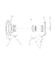
図1,3,5,7,9は、それぞれ、本発明の実施例1〜5のズームレンズのレンズ断面図である。本実施例のズームレンズは、ビデオカメラやデジタルスチルカメラ用の撮影光学系として用いられるものである。 1, 3, 5, 7, and 9 are lens cross-sectional views of zoom lenses of Examples 1 to 5 of the present invention, respectively. The zoom lens of the present embodiment is used as a photographing optical system for a video camera or a digital still camera.
各レンズ断面図において、L1は正の屈折力(光学的パワー=焦点距離の逆数)の第1レンズ群、L2は負の屈折力の第2レンズ群、L3は正の屈折力の第3レンズ群、L4は正の屈折力の第4レンズ群である。SPは開口絞り、Gは光学的ローパスフィルター、赤外カットフィルター、カバーガラス等の光路中に存在する平行平板に対応して設計上設けたガラスブロック、IPはCCDセンサやCMOSセンサ等の固体撮像素子(光電変換素子)の感光面が位置する像面である。 In each lens cross-sectional view, L1 is a first lens group having a positive refractive power (optical power = reciprocal of focal length), L2 is a second lens group having a negative refractive power, and L3 is a third lens having a positive refractive power. The group L4 is a fourth lens group having a positive refractive power. SP is an aperture stop, G is an optical low-pass filter, an infrared cut filter, a glass block designed to correspond to a parallel plate existing in the optical path such as a cover glass, and IP is a solid-state image sensor such as a CCD sensor or a CMOS sensor. It is an image surface on which the photosensitive surface of the element (photoelectric conversion element) is located.
広角端から望遠端へのズーミングに際して、各レンズ断面図中の矢印で示すように、第1レンズ群L1は望遠端で広角端よりも物体側に位置するように、第2レンズ群L2は望遠端で広角端よりも像側に位置するように、第3レンズ群L3は望遠端で広角端よりも物体側に位置するように移動させている。特に、本実施例では第3レンズ群L3を物体側に凸状の軌跡を描くように移動させることで、ズーム中間位置での周辺光線を確保するために前玉径が増大することを低減し、前玉径の小型化を達成している。開口絞りSPは、第3レンズ群L3と一体で光軸上を移動する。 During zooming from the wide-angle end to the telephoto end, the second lens unit L2 is telephoto so that the first lens unit L1 is positioned closer to the object side than the wide-angle end at the telephoto end, as indicated by the arrows in each lens cross-sectional view. The third lens unit L3 is moved so as to be positioned closer to the image side than the wide-angle end at the telephoto end so as to be positioned closer to the image side than the wide-angle end. In particular, in this embodiment, the third lens unit L3 is moved so as to draw a convex locus on the object side, thereby reducing an increase in the front lens diameter in order to secure peripheral rays at the intermediate zoom position. The size of the front lens has been reduced. The aperture stop SP moves on the optical axis integrally with the third lens unit L3.
また広角端に対して望遠端で第1レンズ群が物体側に、第2レンズ群が像側に位置するように移動させることで、レンズ全長を小型に維持しつつ、ズーム比が大きくとれるようにしている。 Further, by moving the first lens unit to the object side and the second lens unit to the image side at the telephoto end with respect to the wide-angle end, the zoom ratio can be increased while maintaining the entire lens length small. I have to.
また、第4レンズ群L4を光軸上移動させてフォーカスを行うリアフォーカス方式を採用している。レンズ断面図に示す第4レンズ群L4の実線の曲線4aと破線の曲線4bは、各々無限遠物体と近距離物体にフォーカスしているときの広角端から望遠端へのズーミングの際の像面変動を補正するための移動軌跡である。このように第4レンズ群L4を物体側へ凸状の軌跡とすることで第3レンズ群L3と第4レンズ群L4との間の空間の有効利用を図り、レンズ全長の短縮化を効果的に達成している。このように、比較的径が小さい第4レンズ群L4でフォーカスを行うことでアクチュエーターの負荷を低減でき、フォーカスの高速化も容易になる。
In addition, a rear focus method is employed in which the fourth lens unit L4 is moved on the optical axis for focusing. The
各実施例において、例えば望遠端において無限遠物体から近距離物体へフォーカスを行う場合は、レンズ断面図の直線4cに示すように第4レンズ群L4を前方へ繰り出す。
In each embodiment, for example, when focusing from an infinitely distant object to a close object at the telephoto end, the fourth lens unit L4 is extended forward as indicated by a
第1レンズ群L1は、物体側から像側へ順に、像側に強い凹面を向けたメニスカス形状の負レンズG11、物体側に強い屈折力の凸面を有する正レンズG12、物体側に凸面を有する正レンズG13で構成されている。第1レンズ群L1をこのようなレンズ構成にすることで、レンズ構成枚数を最小限にしながら、高い光学性能を得ることができる。 The first lens unit L1 has, in order from the object side to the image side, a meniscus negative lens G11 having a strong concave surface facing the image side, a positive lens G12 having a convex surface with strong refractive power on the object side, and a convex surface on the object side. It is composed of a positive lens G13. By setting the first lens unit L1 to such a lens configuration, high optical performance can be obtained while minimizing the number of lens components.
第2レンズ群L2は、物体側から像側へ順に、像側に強い凹面を向けたメニスカス形状の負レンズG21、負レンズG22、正レンズG23で構成されている。第2レンズ群L2をこのようなレンズ構成にすることで、必要最小限のレンズ枚数で高い光学性能を達成できる。 The second lens unit L2 includes, in order from the object side to the image side, a meniscus negative lens G21 having a strong concave surface facing the image side, a negative lens G22, and a positive lens G23. By configuring the second lens unit L2 in such a lens configuration, high optical performance can be achieved with a minimum number of lenses.
第3レンズ群L3は、物体側から像側へ順に、正レンズG31、像側に強い凹面を向けたメニスカス形状の負レンズG32,正レンズG33で構成されている。 The third lens unit L3 includes, in order from the object side to the image side, a positive lens G31, a meniscus negative lens G32 having a strong concave surface facing the image side, and a positive lens G33.
実施例1〜4では、第1レンズ群L1中の正レンズG12の像側のレンズ面に以下の条件を満足する微粒子混合材料より成る、負の屈折力のレプリカ層G1aを設け、波長420nm〜650nm程度の範囲で特に望遠側における軸上及び倍率色収差を良好に補正している。
11<νIT<27 (1)
0.2<θIT<0.4 (2)
但し、νITは微粒子混合材料で構成されたレプリカ層のアッベ数、θITはこのレプリカ層のg線とF線に関する部分分散比であり、g,F,C線に対する屈折率ng,nF,nCに対して、
θ=(ng−nF)/(nF−nC)
で与えられる。
In Examples 1 to 4, a replica layer G1a having a negative refractive power made of a fine particle mixed material satisfying the following conditions is provided on the image-side lens surface of the positive lens G12 in the first lens unit L1, and a wavelength of 420 nm to In the range of about 650 nm, the axial and lateral chromatic aberrations on the telephoto side are particularly well corrected.
11 <νIT <27 (1)
0.2 <θIT <0.4 (2)
Where νIT is the Abbe number of the replica layer made of the fine particle mixed material, θIT is the partial dispersion ratio of the replica layer with respect to the g-line and the F-line , for,
θ = (ng−nF) / (nF−nC)
Given in.
条件式(1)の下限を超えて、微粒子混合材料のアッベ数を小さくしようとするとITO等の混合比率を増やさなければならなくなり、レンズの透過率が悪化してしまうとともに、異常分散効果が大きくなりすぎて色収差補正が過剰になってしまう。逆に上限を超えると色収差補正効果が不十分になる。 Exceeding the lower limit of conditional expression (1) to reduce the Abbe number of the fine particle mixture material, the mixing ratio of ITO or the like must be increased, the lens transmittance deteriorates, and the anomalous dispersion effect is large. As a result, the chromatic aberration correction becomes excessive. Conversely, if the upper limit is exceeded, the chromatic aberration correction effect will be insufficient.
また、条件式(2)の下限を超えて部分分散比を小さくするには、これもITOの混合比率を大きくしなければならず、透過率が悪化するとともに色収差補正が過剰になるので良くない。また条件式(2)の条件を超えて部分分散比が大きくなると色収差補正効果が不十分になるので良くない。 Also, in order to reduce the partial dispersion ratio beyond the lower limit of conditional expression (2), this also requires an increase in the ITO mixing ratio, which is not good because the transmittance deteriorates and chromatic aberration correction becomes excessive. . If the partial dispersion ratio exceeds the condition of conditional expression (2), the chromatic aberration correction effect becomes insufficient, which is not good.
更に望ましく色収差補正条件と透過率を両立させるためには、条件式(1),(2)の範囲を以下のように設定することが望ましい。
13.0<νIT<24.5 (1a)
0.26<θIT<0.36 (2a)
Furthermore, in order to achieve both chromatic aberration correction conditions and transmittance, it is desirable to set the ranges of conditional expressions (1) and (2) as follows.
13.0 <νIT <24.5 (1a)
0.26 <θIT <0.36 (2a)
また、実施例1〜4のように第1レンズ群L1に異常分散の層G1aを設ける場合には、その層G1aの焦点距離をf1a、第1レンズ群L1の焦点距離をf1とするとき、
8<|f1a/f1|<60 (3)
なる条件を満足するのが良い。
Further, when the anomalous dispersion layer G1a is provided in the first lens unit L1 as in Examples 1 to 4, when the focal length of the layer G1a is f1a and the focal length of the first lens unit L1 is f1,
8 <| f1a / f1 | <60 (3)
It is good to satisfy the condition.
条件式(3)の下限を超えて層G1aの屈折力が強くなりすぎると、望遠端における軸上色収差の2次スペクトルの補正が過剰になるので良くない。逆に条件式(3)の上限を超えると軸上色収差の2次スペクトルの補正が不足になるので良くない。 If the lower limit of conditional expression (3) is exceeded and the refractive power of the layer G1a becomes too strong, correction of the secondary spectrum of axial chromatic aberration at the telephoto end becomes excessive, which is not good. Conversely, if the upper limit of conditional expression (3) is exceeded, correction of the secondary spectrum of axial chromatic aberration will be insufficient, which is not good.
更に色収差補正を良好に補正するためには、条件式(3)の範囲を以下のように設定することが望ましい。
8<|f1a/f1|<48 (3a)
Further, in order to correct chromatic aberration correction satisfactorily, it is desirable to set the range of conditional expression (3) as follows.
8 <| f1a / f1 | <48 (3a)
また第1レンズ群L1中の層G1aあるなしに関わらず、レンズ全長の小型化を達成するためには、第1レンズ群L1の焦点距離をf1、全系での望遠端での焦点距離をftとするとき、
0.5<f1/ft<0.9 (4)
なる条件を満足するのが望ましい。
Regardless of the presence or absence of the layer G1a in the first lens unit L1, in order to achieve a reduction in the total lens length, the focal length of the first lens unit L1 is f1, and the focal length at the telephoto end in the entire system is set. When ft,
0.5 <f1 / ft <0.9 (4)
It is desirable to satisfy the following conditions.
条件式(4)の下限を越えて第1レンズ群L1の屈折力が強くなり過ぎると、全長の短縮には有利だが、製造誤差による像面倒れやズーミング時の像ゆれなどが不利になって高い鏡筒精度が必要になり、製造コストの増大を招く。逆に上限を越えると所望のズーム比を確保するのに必要な第1レンズ群L1又は第2レンズ群L2の移動量が大きくなり過ぎて小型化が不十分になるので良くない。 If the refractive power of the first lens unit L1 becomes too strong beyond the lower limit of the conditional expression (4), it is advantageous for shortening the overall length, but image surface tilt due to manufacturing errors and image distortion during zooming become disadvantageous. High lens barrel accuracy is required, leading to an increase in manufacturing cost. On the other hand, if the upper limit is exceeded, the amount of movement of the first lens unit L1 or the second lens unit L2 necessary for securing a desired zoom ratio becomes too large, and the size reduction becomes insufficient.
条件式(4)を更に望ましくは、
0.6<f1/ft<0.8 (4a)
の範囲とすることで更なる小型化と高性能化の両立が可能となる。
More preferably, conditional expression (4) is:
0.6 <f1 / ft <0.8 (4a)
By making this range, it is possible to achieve both further miniaturization and higher performance.
なお、実施例1〜4では、物体側から数えて2番目の正レンズG12の像側面に層G1aを設けているが、3番目の正レンズG3の物体側面又は像側面に層G1aを設けても、同様の効果が得られる。 In Examples 1 to 4, the layer G1a is provided on the image side surface of the second positive lens G12 counted from the object side, but the layer G1a is provided on the object side surface or image side surface of the third positive lens G3. The same effect can be obtained.
実施例2及び4では、第1レンズ群L1に加えて、第2レンズ群L2にも条件式(1),(2)を満足する正の屈折力の層G2aを設けている。具体的には、負レンズG22の像側のレンズ面に層G2aを設けている。 In Examples 2 and 4, in addition to the first lens unit L1, the second lens unit L2 is provided with a positive refractive power layer G2a that satisfies the conditional expressions (1) and (2). Specifically, the layer G2a is provided on the lens surface on the image side of the negative lens G22.
望遠端における軸上色収差や倍率色収差の2次スペクトルを補正するために第1レンズ群L1の異常分散効果を増やしていくと、広角端における倍率色収差の2次スペクトルが悪化する。実施例2及び4では、第2レンズ群L2にも大きな異常分散効果を有する層G2aを設けることにより、広角端における倍率色収差の2次スペクトルを補正し、更に望遠端における軸上及び倍率色収差の改善を達成している。 If the anomalous dispersion effect of the first lens unit L1 is increased in order to correct the secondary spectrum of axial chromatic aberration and lateral chromatic aberration at the telephoto end, the secondary spectrum of lateral chromatic aberration at the wide-angle end deteriorates. In Examples 2 and 4, the second lens unit L2 is also provided with the layer G2a having a large anomalous dispersion effect, thereby correcting the secondary spectrum of lateral chromatic aberration at the wide-angle end, and further reducing the axial and lateral chromatic aberration at the telephoto end. Improvement has been achieved.
第2レンズ群L2に異常分散の層G2aを設ける場合、その層G2aの焦点距離をf2a、第2レンズ群L2の焦点距離をf2とするとき、
12<|f2a/f2|<20 (5)
なる条件式を満足するのが良い。
When the anomalous dispersion layer G2a is provided in the second lens unit L2, when the focal length of the layer G2a is f2a and the focal length of the second lens unit L2 is f2,
12 <| f2a / f2 | <20 (5)
It is good to satisfy the following conditional expression.
条件式(5)の下限を超えて層G2aの屈折力が強くなりすぎると、広角端における倍率色収差の2次スペクトルの補正が過剰になるので良くない。逆に条件式(5)の上限を超えると倍率色収差の2次スペクトルの補正が不足になるので良くない。 If the lower limit of conditional expression (5) is exceeded and the refractive power of the layer G2a becomes too strong, correction of the secondary spectrum of lateral chromatic aberration at the wide-angle end becomes excessive, which is not good. Conversely, if the upper limit of conditional expression (5) is exceeded, correction of the secondary spectrum of lateral chromatic aberration will be insufficient, which is not good.
また第2レンズ群L2中の層G2aあるなしに関わらず、高い光学性能を維持しつつ、レンズ全長の短縮を図るには、
0.10<|f2/ft|<0.20 (6)
なる条件式を満足するのが良い。
In addition, in order to shorten the overall length of the lens while maintaining high optical performance regardless of the presence or absence of the layer G2a in the second lens unit L2,
0.10 <| f2 / ft | <0.20 (6)
It is good to satisfy the following conditional expression.
条件式(6)の下限を超えて第2レンズ群の屈折力が強くなると、ズーム時の第2レンズ群L2の移動量は小さくできるが、ペッツバール和が全体に負に大きくなり像面湾曲の補正が困難になるので良くない。逆に条件式(6)の上限を超えると第2レンズ群の変倍時の移動量が大きくなって小型化が達成できないので良くない。 When the refractive power of the second lens unit becomes stronger beyond the lower limit of conditional expression (6), the amount of movement of the second lens unit L2 during zooming can be reduced, but the Petzval sum increases negatively as a whole and the field curvature is increased. It is not good because correction becomes difficult. On the other hand, if the upper limit of conditional expression (6) is exceeded, the amount of movement of the second lens unit at the time of zooming becomes large, and it is not good because downsizing cannot be achieved.
更に望ましくは条件式(6)を、
0.13<|f2/ft|<0.17 (6a)
の範囲に設定すると更なる小型化と高性能化の両立が容易となる。
More preferably, conditional expression (6)
0.13 <| f2 / ft | <0.17 (6a)
If it is set in the range, it becomes easy to achieve both further miniaturization and higher performance.
なお、実施例2及び4では、負レンズG22の像側のレンズ面に層G2aを設けたが、負レンズG21や正レンズG23のレンズ面に正の屈折力の層G2aを設けても良い。 In Examples 2 and 4, the layer G2a is provided on the image-side lens surface of the negative lens G22. However, a layer G2a having a positive refractive power may be provided on the lens surfaces of the negative lens G21 and the positive lens G23.
実施例3では第1レンズ群L1に加えて第3レンズ群L3にも、実施例5では第3レンズ群L3のみに条件式(1),(2)を満足する異常分散効果を持ち、負の屈折力の層G3aを設けている。具体的には、正レンズG31の像側に層G3aを設けている。このように実施例3及び5では、第3レンズ群L3に異常分散効果を持たせることにより、望遠端における軸上色収差を改善している。 In Example 3, in addition to the first lens unit L1, the third lens unit L3 also has an anomalous dispersion effect that satisfies the conditional expressions (1) and (2) only in the third lens unit L3 in Example 5, and is negative. The refractive power layer G3a is provided. Specifically, the layer G3a is provided on the image side of the positive lens G31. As described above, in Examples 3 and 5, axial chromatic aberration at the telephoto end is improved by providing the third lens unit L3 with an anomalous dispersion effect.
第3レンズ群L3に異常分散の層G3aを設ける場合、その層G3aの焦点距離をf3a、第3レンズ群L3の焦点距離をf3とするとき、
6.0<|f3a/f3|<30 (7)
なる条件を満足するのが良い。
When the anomalous dispersion layer G3a is provided in the third lens unit L3, when the focal length of the layer G3a is f3a and the focal length of the third lens unit L3 is f3,
6.0 <| f3a / f3 | <30 (7)
It is good to satisfy the condition.
条件式(7)の下限を超えて層G3aの屈折力が強くなりすぎると、広角端における軸上色収差の2次スペクトルが悪化するので良くない。逆に条件式(7)の上限を超えると、望遠端での軸上色収差の2次スペクトルの補正が不足になるので良くない。 If the lower limit of conditional expression (7) is exceeded and the refractive power of the layer G3a becomes too strong, the secondary spectrum of axial chromatic aberration at the wide-angle end will deteriorate, which is not good. On the contrary, if the upper limit of conditional expression (7) is exceeded, correction of the secondary spectrum of axial chromatic aberration at the telephoto end becomes insufficient, which is not good.
更により良好に色収差補正を補正するためには、条件式(7)の範囲を以下のごとく設定するのが望ましい。
8.0<|f3a/f3|<23 (7a)
In order to further correct chromatic aberration correction, it is desirable to set the range of conditional expression (7) as follows.
8.0 <| f3a / f3 | <23 (7a)
また第3レンズ群L3中の層G3aあるなしに関わらず、レンズ全長の小型化を達成するためには、
0.3<f3/ft<0.45 (8)
なる条件を満足するのが良い。
In order to achieve a reduction in the overall length of the lens regardless of the presence or absence of the layer G3a in the third lens unit L3,
0.3 <f3 / ft <0.45 (8)
It is good to satisfy the condition.
条件式(8)の下限を超えて第3レンズ群L3の焦点距離が小さくなると、ペッツバール和が正に大きくなり過ぎて像面湾曲の補正が困難になる。逆に上限を超えると第3レンズ群L3の変倍への寄与が小さくなって所望のズーム比を得るために第1レンズ群L1及び第2レンズ群L2の移動量が増えてレンズ全長が大きくなってしまうので良くない。 If the lower limit of conditional expression (8) is exceeded and the focal length of the third lens unit L3 becomes small, the Petzval sum becomes too large and correction of field curvature becomes difficult. On the other hand, if the upper limit is exceeded, the contribution of the third lens unit L3 to zooming is reduced, and in order to obtain a desired zoom ratio, the amount of movement of the first lens unit L1 and the second lens unit L2 increases and the total lens length increases. It will be bad.
なお、実施例1〜5では条件式(1),(2)を満足する材料の層を球面として形成しているが、ここに非球面を導入すれば、更に球面収差や歪曲などの諸収差を良好に補正することができる。 In Examples 1 to 5, the material layer satisfying the conditional expressions (1) and (2) is formed as a spherical surface. However, if an aspherical surface is introduced here, various aberrations such as spherical aberration and distortion are further introduced. Can be corrected satisfactorily.
次に上述した実施例1〜5に対応する数値実施例1〜5の数値データを示す。数値実施例において、fは焦点距離、FnoはFナンバー、ωは半画角である。iは物体側より数えた順序を示し、Riは第i番目の面の曲率半径、Diは第i番目の面と第(i+1)番目の面との軸上間隔、Niとνiは各々第i番目の材料のd線を基準とした屈折率とアッベ数である。但し、条件式(1),(2)満足するレプリカ層は別途Nja、νja(j=1〜3 第jレンズ群)で別に示している。 Next, numerical data of numerical examples 1 to 5 corresponding to the above-described examples 1 to 5 will be shown. In the numerical examples, f is a focal length, Fno is an F number, and ω is a half angle of view. i indicates the order counted from the object side, Ri is the radius of curvature of the i-th surface, Di is the axial distance between the i-th surface and the (i + 1) -th surface, and Ni and νi are i-th, respectively. The refractive index and the Abbe number based on the d-line of the second material. However, the replica layers satisfying the conditional expressions (1) and (2) are separately shown as Nja and νja (j = 1 to 3rd lens group).
非球面形状は、光の進行方向を正とし、Xを光軸方向の面頂点からの変位量、hを光軸と垂直な方向の光軸からの高さ、Rを近軸曲率半径、kを円錐定数、B〜E,A′〜C′を各々非球面係数とするとき、 In the aspherical shape, the traveling direction of light is positive, X is the amount of displacement from the surface vertex in the optical axis direction, h is the height from the optical axis in the direction perpendicular to the optical axis, R is the paraxial radius of curvature, k Is a conic constant, and B to E and A 'to C' are aspherical coefficients, respectively.

なる式で表している。 It is expressed by the following formula.
又前述の各条件式と数値実施例の関係を表1に示す。 Table 1 shows the relationship between the above-described conditional expressions and numerical examples.
次に実施例1〜5のズームレンズを撮影光学系として用いた光学機器の実施例を、図11,12を用いて説明する。 Next, an example of an optical apparatus using the zoom lenses of Examples 1 to 5 as a photographing optical system will be described with reference to FIGS.
図11は、本発明のズームレンズをビデオカメラに用いた例である。図11において、10はカメラ本体、11は実施例1〜5のズームレンズによって構成された撮影光学系、12は撮影光学系11によって形成される被写体像を受光するCCDセンサやCMOSセンサ等の固体撮像素子(光電変換素子)、13は固体撮像素子12が受光した被写体像を記録するメモリ、14は被写体像を観察するためのファインダーである。ファインダー14としては、光学ファインダーや液晶パネル等の表示素子に表示された被写体像を観察するタイプのファインダーが考えられる。
FIG. 11 shows an example in which the zoom lens of the present invention is used in a video camera. In FIG. 11, 10 is a camera body, 11 is a photographing optical system constituted by the zoom lenses of Examples 1 to 5, and 12 is a solid state such as a CCD sensor or a CMOS sensor that receives a subject image formed by the photographing
図12は、本発明のズームレンズをデジタルスチルカメラに用いた例である。図12において、20はカメラ本体、21は実施例1〜5で説明したいずれかのズームレンズによって構成された撮影光学系、22はカメラ本体に内蔵され、撮影光学系21によって形成された被写体像を受光するCCDセンサやCMOSセンサ等の固体撮像素子(光電変換素子)、23は固体撮像素子22によって光電変換された被写体像に対応する情報を記録するメモリ、24は液晶ディスプレイパネル等によって構成され、固体撮像素子22上に形成された被写体像を観察するためのファインダーである。
FIG. 12 shows an example in which the zoom lens of the present invention is used in a digital still camera. In FIG. 12, reference numeral 20 denotes a camera body, 21 denotes a photographing optical system constituted by any of the zoom lenses described in the first to fifth embodiments, and 22 denotes a subject image built in the camera body and formed by the photographing
このように本発明のズームレンズをビデオカメラやデジタルスチルカメラ等の撮像装置に適用することにより、小型で高い光学性能を有する撮像装置が実現できる。 Thus, by applying the zoom lens of the present invention to an imaging apparatus such as a video camera or a digital still camera, an imaging apparatus having a small size and high optical performance can be realized.
以上説明した実施例においては、ITO微粒子を合成樹脂中に分散させた混合体で条件式(1)及び(2)を満足する光学材料を実現した。しかし、合成樹脂中に分散させる微粒子材料はITOに限られるものではなく、TiO2(nd=2.2652,νd=11.8),Nb2O5(nd=2.367,νd=14.0),Cr2O3(nd=2.2178,νd=13.4),BaTiO3(nd=2.4362,νd=11.3)等のその他の無機酸化物微粒子も利用することもできる。 In the embodiment described above, an optical material satisfying the conditional expressions (1) and (2) is realized by a mixture in which ITO fine particles are dispersed in a synthetic resin. However, the fine particle material dispersed in the synthetic resin is not limited to ITO, and TiO 2 (nd = 2.2652, νd = 11.8), Nb 2 O 5 (nd = 2.367, νd = 14. 0), Cr 2 O 3 (nd = 2.2178, νd = 13.4), BaTiO 3 (nd = 2.4362, νd = 11.3) and other inorganic oxide fine particles can also be used.
また、無機酸化物微粒子を分散させる樹脂材料としては、モノマーの光学定数の特性としても、アッベ数が比較的小さいモノマーか部分分散比が比較的小さいモノマー、あるいは、両者を満たすモノマーが良い。本実施例ではくPMMAを用いたが、その他の樹脂材料、例えばN−ポリビニルカルバゾール、スチレンな等も利用できる。 The resin material for dispersing the inorganic oxide fine particles is preferably a monomer having a relatively small Abbe number, a relatively small partial dispersion ratio, or a monomer satisfying both of the characteristics of the optical constant of the monomer. Although PMMA is used in this embodiment, other resin materials such as N-polyvinylcarbazole and styrene can be used.
L1 第1レンズ群
L2 第2レンズ群
L3 第3レンズ群
L4 第4レンズ群
d d線
g g線
ΔM メリディオナル像面
ΔS サジタル像面
L1 First lens group L2 Second lens group L3 Third lens group L4 Fourth lens group d d line g g line ΔM meridional image plane ΔS sagittal image plane
Claims (9)
11<νIT<27
0.2<θIT<0.4
を満足する材料より成るレンズ又は層GITを有し、該レンズ又は層GITは、負の屈折力であって、前記レンズ又は層GITの焦点距離をf1a、前記第1レンズ群の焦点距離をf1、全系の望遠端における焦点距離をftとするとき、
8<|f1a/f1|<60
0.5<f1/ft<0.9
なる条件を満足することを特徴とするズームレンズ。 In order from the object side to the image side, a first lens group having a positive refractive power, a second lens group having a negative refractive power, a third lens group having a positive refractive power, and a fourth lens group having a positive refractive power, During zooming, the first lens group moves at the telephoto end so as to be positioned closer to the object side than the wide-angle end, and the second lens group moves at the telephoto end so as to be positioned closer to the image side than the wide-angle end, In the zoom lens in which the third lens group moves along a convex locus on the object side so as to be positioned on the object side relative to the wide-angle end at the telephoto end, and the fourth lens group moves along a convex locus toward the object side , When the Abbe number of the lens or layer GIT is νIT, and the partial dispersion ratio regarding the g-line and F-line of the lens or layer GIT is θIT, the first lens group is
11 <νIT <27
0.2 <θIT <0.4
The lens or layer GIT has a negative refractive power, and the focal length of the lens or layer GIT is f1a, and the focal length of the first lens group is f1. When the focal length at the telephoto end of the entire system is ft,
8 <| f1a / f1 | <60
0.5 <f1 / ft <0.9
A zoom lens that satisfies the following conditions:
11<νIT<27
0.2<θIT<0.4
を満足する材料より成るレンズ又は層GITを有し、該レンズ又は層GITは、正の屈折力であって、前記レンズ又は層GITの焦点距離をf2a、前記第2レンズ群の焦点距離をf2、全系の望遠端における焦点距離をftとするとき、
12<|f2a/f2|<20
0.10<|f2/ft|<0.20
なる条件を満足することを特徴とするズームレンズ。 In order from the object side to the image side, a first lens group having a positive refractive power, a second lens group having a negative refractive power, a third lens group having a positive refractive power, and a fourth lens group having a positive refractive power, During zooming, the first lens group moves at the telephoto end so as to be positioned closer to the object side than the wide-angle end, and the second lens group moves at the telephoto end so as to be positioned closer to the image side than the wide-angle end, In the zoom lens in which the third lens group moves along a convex locus on the object side so as to be positioned on the object side relative to the wide-angle end at the telephoto end, and the fourth lens group moves along a convex locus toward the object side , When the Abbe number of the lens or layer GIT is νIT, and the partial dispersion ratio regarding the g-line and F-line of the lens or layer GIT is θIT, the second lens group is
11 <νIT <27
0.2 <θIT <0.4
The lens or layer GIT is made of a material that satisfies the following conditions. The lens or layer GIT has a positive refractive power, and the focal length of the lens or layer GIT is f2a, and the focal length of the second lens group is f2. When the focal length at the telephoto end of the entire system is ft,
12 <| f2a / f2 | <20
0.10 <| f2 / ft | <0.20
A zoom lens that satisfies the following conditions:
11<νIT<27
0.2<θIT<0.4
を満足する材料より成るレンズ又は層GITを有し、該レンズ又は層GITは、負の屈折力であって、前記レンズ又は層GITの焦点距離をf3a、前記第3レンズ群の焦点距離をf3、全系の望遠端における焦点距離をftとするとき、
6<|f3a/f3|<30
0.3<f3/ft<0.45
なる条件を満足することを特徴とするズームレンズ。 In order from the object side to the image side, a first lens group having a positive refractive power, a second lens group having a negative refractive power, a third lens group having a positive refractive power, and a fourth lens group having a positive refractive power, During zooming, the first lens group moves at the telephoto end so as to be positioned closer to the object side than the wide-angle end, and the second lens group moves at the telephoto end so as to be positioned closer to the image side than the wide-angle end, In the zoom lens in which the third lens group moves along a convex locus on the object side so as to be positioned on the object side relative to the wide-angle end at the telephoto end, and the fourth lens group moves along a convex locus toward the object side , When the Abbe number of the lens or layer GIT is νIT, and the partial dispersion ratio regarding the g-line and F-line of the lens or layer GIT is θIT, the third lens group is
11 <νIT <27
0.2 <θIT <0.4
The lens or layer GIT is made of a material that satisfies the following conditions. The lens or layer GIT has negative refractive power, and the focal length of the lens or layer GIT is f3a, and the focal length of the third lens group is f3. When the focal length at the telephoto end of the entire system is ft,
6 <| f3a / f3 | <30
0.3 <f3 / ft <0.45
A zoom lens that satisfies the following conditions:
Priority Applications (2)
| Application Number | Priority Date | Filing Date | Title |
|---|---|---|---|
| JP2004132608A JP4636812B2 (en) | 2004-04-28 | 2004-04-28 | Zoom lens |
| US11/113,583 US7088521B2 (en) | 2004-04-28 | 2005-04-25 | Zoom lens system |
Applications Claiming Priority (1)
| Application Number | Priority Date | Filing Date | Title |
|---|---|---|---|
| JP2004132608A JP4636812B2 (en) | 2004-04-28 | 2004-04-28 | Zoom lens |
Publications (3)
| Publication Number | Publication Date |
|---|---|
| JP2005316047A JP2005316047A (en) | 2005-11-10 |
| JP2005316047A5 JP2005316047A5 (en) | 2007-06-14 |
| JP4636812B2 true JP4636812B2 (en) | 2011-02-23 |
Family
ID=35186796
Family Applications (1)
| Application Number | Title | Priority Date | Filing Date |
|---|---|---|---|
| JP2004132608A Expired - Fee Related JP4636812B2 (en) | 2004-04-28 | 2004-04-28 | Zoom lens |
Country Status (2)
| Country | Link |
|---|---|
| US (1) | US7088521B2 (en) |
| JP (1) | JP4636812B2 (en) |
Families Citing this family (22)
| Publication number | Priority date | Publication date | Assignee | Title |
|---|---|---|---|---|
| JP4426946B2 (en) * | 2004-10-27 | 2010-03-03 | オリンパス株式会社 | Digital camera system |
| JP2005181392A (en) * | 2003-12-16 | 2005-07-07 | Canon Inc | Optical system |
| JP4612810B2 (en) * | 2004-06-11 | 2011-01-12 | キヤノン株式会社 | Optical system |
| JP2006133632A (en) * | 2004-11-09 | 2006-05-25 | Olympus Corp | Zoom lens |
| US7898743B2 (en) * | 2005-09-13 | 2011-03-01 | Olympus Corporation | Image forming optical system and electronic image pickup apparatus using image forming optical system |
| JP4881035B2 (en) * | 2006-02-27 | 2012-02-22 | キヤノン株式会社 | Zoom lens and imaging apparatus having the same |
| JP4829668B2 (en) * | 2006-04-27 | 2011-12-07 | キヤノン株式会社 | Zoom lens and imaging apparatus having the same |
| JP4898307B2 (en) * | 2006-06-05 | 2012-03-14 | キヤノン株式会社 | Optical system and optical apparatus having the same |
| JP4898410B2 (en) * | 2006-12-14 | 2012-03-14 | キヤノン株式会社 | Zoom lens and imaging apparatus having the same |
| JPWO2008072466A1 (en) * | 2006-12-14 | 2010-03-25 | コニカミノルタオプト株式会社 | Variable-magnification optical system, imaging device, and digital device |
| JP5028110B2 (en) * | 2007-02-28 | 2012-09-19 | キヤノン株式会社 | Zoom lens and imaging apparatus having the same |
| NL1034857C2 (en) * | 2007-12-21 | 2009-06-23 | Anteryon B V | Optical system. |
| JP5202014B2 (en) * | 2008-02-08 | 2013-06-05 | キヤノン株式会社 | Optical system and optical instrument using the same |
| JP5344549B2 (en) * | 2008-08-08 | 2013-11-20 | キヤノン株式会社 | Zoom lens and imaging apparatus having the same |
| JP2010091881A (en) | 2008-10-09 | 2010-04-22 | Olympus Imaging Corp | Imaging optical system and electronic imaging apparatus having the same |
| JP5751991B2 (en) * | 2011-08-30 | 2015-07-22 | キヤノン株式会社 | Zoom lens and imaging apparatus having the same |
| JP5159941B2 (en) * | 2011-11-08 | 2013-03-13 | キヤノン株式会社 | Zoom lens and imaging apparatus having the same |
| JP2013200543A (en) | 2012-02-22 | 2013-10-03 | Olympus Imaging Corp | Zoom lens and imaging device including the same |
| JPWO2014129175A1 (en) * | 2013-02-25 | 2017-02-02 | パナソニックIpマネジメント株式会社 | Optical lens |
| JP6304967B2 (en) * | 2013-08-05 | 2018-04-04 | キヤノン株式会社 | Zoom lens and imaging apparatus having the same |
| JP2017102201A (en) * | 2015-11-30 | 2017-06-08 | 株式会社ニコン | Zoom lens, optical instrument, and zoom lens manufacturing method |
| JP7413044B2 (en) * | 2020-01-27 | 2024-01-15 | キヤノン株式会社 | Zoom lens and imaging device and imaging system having the same |
Citations (6)
| Publication number | Priority date | Publication date | Assignee | Title |
|---|---|---|---|---|
| JPH0634886A (en) * | 1992-07-20 | 1994-02-10 | Olympus Optical Co Ltd | Variable power lens |
| JPH08220439A (en) * | 1995-02-17 | 1996-08-30 | Olympus Optical Co Ltd | Zoom lens |
| JP2001074901A (en) * | 1999-07-01 | 2001-03-23 | Canon Inc | Optical material and optical system using the same |
| JP2001154093A (en) * | 1999-11-24 | 2001-06-08 | Olympus Optical Co Ltd | Small-sized high variable power wide-angle zoom lens |
| JP2001194590A (en) * | 1999-10-29 | 2001-07-19 | Minolta Co Ltd | Image pickup lens device |
| JP2003295059A (en) * | 2002-04-04 | 2003-10-15 | Canon Inc | Zoom lens and optical equipment having the same |
Family Cites Families (7)
| Publication number | Priority date | Publication date | Assignee | Title |
|---|---|---|---|---|
| JP3097399B2 (en) | 1993-06-23 | 2000-10-10 | キヤノン株式会社 | Rear focus telephoto zoom lens |
| US5568325A (en) * | 1993-08-25 | 1996-10-22 | Asahi Kogaku Kogyo Kabushiki Kaisha | Achromatic lens system |
| JPH08248317A (en) | 1995-03-13 | 1996-09-27 | Olympus Optical Co Ltd | Zoom lens |
| JP3144292B2 (en) | 1996-02-06 | 2001-03-12 | ミノルタ株式会社 | Zoom lens |
| JP2001021803A (en) | 1999-07-05 | 2001-01-26 | Sony Corp | Zoom lens |
| JP2002062478A (en) | 2000-08-22 | 2002-02-28 | Olympus Optical Co Ltd | Zoom lens |
| JP3920655B2 (en) * | 2002-02-14 | 2007-05-30 | オリンパス株式会社 | Zoom lens and imaging apparatus using the same |
-
2004
- 2004-04-28 JP JP2004132608A patent/JP4636812B2/en not_active Expired - Fee Related
-
2005
- 2005-04-25 US US11/113,583 patent/US7088521B2/en not_active Expired - Fee Related
Patent Citations (6)
| Publication number | Priority date | Publication date | Assignee | Title |
|---|---|---|---|---|
| JPH0634886A (en) * | 1992-07-20 | 1994-02-10 | Olympus Optical Co Ltd | Variable power lens |
| JPH08220439A (en) * | 1995-02-17 | 1996-08-30 | Olympus Optical Co Ltd | Zoom lens |
| JP2001074901A (en) * | 1999-07-01 | 2001-03-23 | Canon Inc | Optical material and optical system using the same |
| JP2001194590A (en) * | 1999-10-29 | 2001-07-19 | Minolta Co Ltd | Image pickup lens device |
| JP2001154093A (en) * | 1999-11-24 | 2001-06-08 | Olympus Optical Co Ltd | Small-sized high variable power wide-angle zoom lens |
| JP2003295059A (en) * | 2002-04-04 | 2003-10-15 | Canon Inc | Zoom lens and optical equipment having the same |
Also Published As
| Publication number | Publication date |
|---|---|
| US7088521B2 (en) | 2006-08-08 |
| US20050243438A1 (en) | 2005-11-03 |
| JP2005316047A (en) | 2005-11-10 |
Similar Documents
| Publication | Publication Date | Title |
|---|---|---|
| JP4881035B2 (en) | Zoom lens and imaging apparatus having the same | |
| JP4636812B2 (en) | Zoom lens | |
| JP4630645B2 (en) | Optical system | |
| JP4819447B2 (en) | Optical system and imaging apparatus having the same | |
| JP5028104B2 (en) | Zoom lens and imaging apparatus having the same | |
| JP5339784B2 (en) | Zoom lens and imaging apparatus having the same | |
| EP2620796B1 (en) | Optical system and imaging apparatus | |
| JP5388446B2 (en) | Optical system and optical apparatus having the same | |
| JP4829668B2 (en) | Zoom lens and imaging apparatus having the same | |
| EP2090916B1 (en) | Retrofocus objective using lenses exhibiting relative partial dispersion | |
| JP4914136B2 (en) | Zoom lens and imaging apparatus having the same | |
| US7486448B2 (en) | Zoom lens and image pickup apparatus | |
| JP5196822B2 (en) | Zoom lens and imaging apparatus having the same | |
| US7492526B2 (en) | High zoom ratio zoom lens, optical apparatus using the same, and method for varying focal length | |
| US20070002462A1 (en) | Zoom lens system | |
| JP4794915B2 (en) | Zoom lens and imaging apparatus having the same | |
| US8085478B2 (en) | Zoom lens system and image pickup apparatus including the same | |
| JP2010060612A (en) | Zoom lens and image pickup device including the same | |
| JP5111046B2 (en) | Zoom lens and imaging apparatus having the same | |
| US8873155B2 (en) | Zoom lens and image pickup apparatus having the same | |
| CN112578542B (en) | Zoom lens and image pickup apparatus including the same | |
| JP5395495B2 (en) | Variable magnification optical system | |
| US8736972B2 (en) | Zoom lens, optical apparatus and method for manufacturing zoom lens | |
| JP2023171585A (en) | Zoom optical system, optical device, and method of manufacturing zoom optical system | |
| US20090296233A1 (en) | Zoom lens system and camera including the same |
Legal Events
| Date | Code | Title | Description |
|---|---|---|---|
| A521 | Written amendment |
Free format text: JAPANESE INTERMEDIATE CODE: A523 Effective date: 20070425 |
|
| A621 | Written request for application examination |
Free format text: JAPANESE INTERMEDIATE CODE: A621 Effective date: 20070425 |
|
| RD04 | Notification of resignation of power of attorney |
Free format text: JAPANESE INTERMEDIATE CODE: A7424 Effective date: 20100201 |
|
| A131 | Notification of reasons for refusal |
Free format text: JAPANESE INTERMEDIATE CODE: A131 Effective date: 20100601 |
|
| RD01 | Notification of change of attorney |
Free format text: JAPANESE INTERMEDIATE CODE: A7421 Effective date: 20100630 |
|
| A521 | Written amendment |
Free format text: JAPANESE INTERMEDIATE CODE: A523 Effective date: 20100802 |
|
| A131 | Notification of reasons for refusal |
Free format text: JAPANESE INTERMEDIATE CODE: A131 Effective date: 20100824 |
|
| A521 | Written amendment |
Free format text: JAPANESE INTERMEDIATE CODE: A523 Effective date: 20101025 |
|
| TRDD | Decision of grant or rejection written | ||
| A01 | Written decision to grant a patent or to grant a registration (utility model) |
Free format text: JAPANESE INTERMEDIATE CODE: A01 Effective date: 20101116 |
|
| A01 | Written decision to grant a patent or to grant a registration (utility model) |
Free format text: JAPANESE INTERMEDIATE CODE: A01 |
|
| A61 | First payment of annual fees (during grant procedure) |
Free format text: JAPANESE INTERMEDIATE CODE: A61 Effective date: 20101122 |
|
| FPAY | Renewal fee payment (event date is renewal date of database) |
Free format text: PAYMENT UNTIL: 20131203 Year of fee payment: 3 |
|
| R150 | Certificate of patent or registration of utility model |
Free format text: JAPANESE INTERMEDIATE CODE: R150 |
|
| LAPS | Cancellation because of no payment of annual fees |