JP5395495B2 - Variable magnification optical system - Google Patents
Variable magnification optical system Download PDFInfo
- Publication number
- JP5395495B2 JP5395495B2 JP2009091645A JP2009091645A JP5395495B2 JP 5395495 B2 JP5395495 B2 JP 5395495B2 JP 2009091645 A JP2009091645 A JP 2009091645A JP 2009091645 A JP2009091645 A JP 2009091645A JP 5395495 B2 JP5395495 B2 JP 5395495B2
- Authority
- JP
- Japan
- Prior art keywords
- lens
- lens group
- cemented
- refractive power
- optical system
- Prior art date
- Legal status (The legal status is an assumption and is not a legal conclusion. Google has not performed a legal analysis and makes no representation as to the accuracy of the status listed.)
- Active
Links
Images


Description
本発明は、一眼レフレックス方式のファインダーや色分解プリズム等のための長いバックフォーカスが必要な撮像装置に最適な、広角端の画角が100度以上で、変倍比が1.8以上である超広角の変倍結像光学系に関するものである。 The present invention is suitable for an imaging apparatus that requires a long back focus for a single-lens reflex finder, a color separation prism, and the like, and has an angle of view at a wide angle end of 100 degrees or more and a zoom ratio of 1.8 or more. The present invention relates to an ultra-wide-angle variable magnification imaging optical system.
近年、固体撮像素子を備えたレンズ交換式のデジタル一眼レフカメラが普及している。この多くは135フイルムを使用するレンズ交換式のフイルム一眼レフカメラと共通のレンズマウントを備えており、デジタル一眼レフカメラにはフイルム一眼レフカメラの交換レンズが装着できる。 In recent years, interchangeable-lens digital single-lens reflex cameras equipped with solid-state imaging devices have become widespread. Many of these cameras have a lens mount that is common to interchangeable lens single-lens reflex cameras that use 135 film, and digital single-lens reflex cameras can be equipped with interchangeable lenses for film single-lens reflex cameras.
しかしながら、大型の固体撮像素子は非常に高価であるため、デジタル一眼レフカメラの多くは所謂APS−Cサイズの固体撮像素子を採用している。APS−Cサイズは、135フイルムを使用するフイルムカメラにおいて最も一般的な、所謂35mmフルサイズと呼ばれる36mm×24mmのフイルムサイズに対して対角線長がおよそ2/3程度のサイズである。 However, since large solid-state image sensors are very expensive, many digital single-lens reflex cameras employ so-called APS-C size solid-state image sensors. The APS-C size has a diagonal length of about 2/3 with respect to a film size of 36 mm × 24 mm called a so-called 35 mm full size, which is most common in a film camera using a 135 film.
APS−Cサイズの固体撮像素子を備えたデジタル一眼レフカメラを用いて、100度を超える画角の写真を撮影するためには、35mmフルサイズの固体撮像素子を備えたデジタル一眼レフカメラを用いて122度以上の画角が撮影できるレンズが必要となる。さらに、135フイルムを使用するフイルム一眼レフカメラと共通のレンズマウントを備え、APS−Cサイズの固体撮像素子を採用するデジタル一眼レフカメラを用いて100度を超える画角の写真を撮影するためには、焦点距離の3倍以上若しくはそれ以上のバックフォーカスを確保する必要がある。 Using a digital single-lens reflex camera equipped with an APS-C size solid-state image sensor, a digital single-lens reflex camera equipped with a 35 mm full-size solid-state image sensor is used to take a photograph with an angle of view exceeding 100 degrees. Therefore, a lens capable of photographing an angle of view of 122 degrees or more is required. Furthermore, in order to take a photograph with an angle of view exceeding 100 degrees using a digital single-lens reflex camera equipped with a lens mount common to a film single-lens reflex camera using a 135 film and adopting an APS-C size solid-state image sensor. Therefore, it is necessary to secure a back focus that is at least three times the focal length or more.
十分なバックフォーカスを確保し、35mmフルサイズの固体撮像素子を備えるデジタル一眼レフカメラを用いて広角端の画角で約122度の写真を撮影可能とした変倍結像光学系が、特許文献1に記載されている。 A variable-magnification imaging optical system that can capture a photograph of about 122 degrees at a wide-angle end using a digital single-lens reflex camera that has a sufficient back focus and a 35 mm full-size solid-state image sensor. 1.
また、イメージサークルをAPS-Cサイズに対応する大きさに制限することで、APS-Cサイズの固体撮像素子を備えるデジタル一眼レフカメラを用いて100度を超える画角の写真を撮影可能な変倍結像光学系も提案されており、例えば特許文献2乃至特許文献6に記載されている。
In addition, by limiting the image circle to a size corresponding to the APS-C size, it is possible to take a photograph with an angle of view exceeding 100 degrees using a digital single-lens reflex camera equipped with a solid-state image sensor of APS-C size. Double imaging optical systems have also been proposed, and are described in, for example,
長いバックフォーカスを確保しつつ、光学系全体をコンパクトにまとめ、かつFナンバーを小さくして高画質を保つためには、高度な収差補正を必要とする。 In order to keep the entire optical system compact and to maintain a high image quality by reducing the F-number while ensuring a long back focus, advanced aberration correction is required.
特許文献1に記載の変倍結像光学系は十分なバックフォーカスを確保しているが、35mmフルサイズのイメージサークルに対応するため、最も物体側に位置するレンズ径が大きくなっている。また、最も物体側に位置するレンズの曲率がきつくなっているため光学系の物体側にフィルタを装着することができない。
Although the variable magnification imaging optical system described in
特許文献2及び3に記載の変倍結像光学系は変倍全域におけるFナンバーの最大値が4程度となっているものの、大口径化が十分であるとは言い難い。
In the variable magnification imaging optical systems described in
特許文献4及び5には十分なバックフォーカスを備えながらFナンバーが3.6程度、かつ変倍比2.3倍程度の変倍結像光学系が記載されているが、非点収差やコマ収差の補正が不十分で、近年、一段と高画質化したデジタルカメラに十分に対応できない。さらに、後群に3枚のレンズエレメント張り合わせた接合レンズを備えており、2枚のレンズエレメントからなる接合レンズに比べて製造の難易度が高くなる。また、光学系の像側に近い部分のレンズにおいて偏芯に対する収差変動の感度が極めて高くなってしまっており、製造コストが高くなる懸念がある。
特許文献6に記載の変倍結像光学系は、変倍全域においてFナンバーが2.9程度の大口径を実現しているが、特に中間域における倍率色収差やコマ収差、サジタル像面の補正等が不十分で多くの光学性能に改善の余地がある。 The variable magnification imaging optical system described in Patent Document 6 achieves a large aperture with an F-number of about 2.9 in the entire variable magnification range, but in particular, correction of lateral chromatic aberration, coma aberration, and sagittal image plane in the intermediate range. There is room for improvement in many optical performances.
本発明は、広角端において画角が100度以上で、変倍費1.8倍以上の変倍結像光学系であって、変倍全域においてFナンバーが3.6程度で、かつ諸収差が良好に補正されたコンパクトな変倍結像光学系を提供することを目的とする。 The present invention is a variable-magnification imaging optical system having an angle of view of 100 degrees or more at the wide-angle end and a magnification change cost of 1.8 times or more. An object of the present invention is to provide a compact variable magnification imaging optical system in which is corrected well.
本発明により、物体側より順に、負の屈折力を持つ第1レンズ群と、正の屈折力を持つ第2レンズ群と、負の屈折力を持つ第3レンズ群と、正の屈折力を持つ第4レンズ群とからなり、広角端から望遠端への変倍に際して、隣接する各レンズ群同士の間隔が変化し、少なくとも該第1レンズ群、該第2レンズ群、及び該第4レンズ群を光軸に沿う方向へ移動させ、該第2レンズ群から該第4レンズ群までの合成屈折力は変倍全域において常に正であり、前記第1レンズ群は最も物体側から順に少なくとも2枚の負レンズを備えるとともに、最も物体側のレンズは負の屈折力を備え、物体側に凸のメニスカス形状であり、少なくとも1つのレンズ面が非球面形状であって、前記第4レンズ群中には屈折力符号の異なるレンズエレメントの貼り合わせより構成される少なくとも1つの接合レンズLcを備え、以下の条件式を満足することを特徴とする変倍結像光学系を提供する。
(1)0.55<|βwr|<0.75
(2)2.6<β2w/β4w<8.5
(3)3.5<νp/νn
ただし、
βwr:第2レンズ群から第4レンズ群の広角端かつ無限遠結像状態における合成結像倍率
νp:第4レンズ群の何れかの接合レンズLcを構成する正レンズのd線(波長587.6nm)基準のアッベ数
νn:第4レンズ群の何れかの接合レンズLcを構成する負レンズのd線(波長587.6nm)基準のアッベ数
βiw:第iレンズ群の広角端かつ無限遠結像状態における結像倍率
According to the present invention, in order from the object side, a first lens group having a negative refractive power, a second lens group having a positive refractive power, a third lens group having a negative refractive power, and a positive refractive power having made the fourth lens group, upon zooming from the wide-angle end to the telephoto end, the interval between the lens units adjacent to each change, at least the first lens group, second lens group and the fourth lens The group is moved in the direction along the optical axis, and the combined refractive power from the second lens group to the fourth lens group is always positive in the entire zoom range, and the first lens group is at least 2 in order from the most object side. A negative lens, the lens closest to the object side has a negative refractive power, has a meniscus shape convex toward the object side, and at least one lens surface has an aspherical shape. For lens elements with different refractive power signs Seyori configured with at least one cemented lens Lc, provides a variable magnification imaging optical system, characterized by satisfying the following conditional expression.
(1) 0.55 <| βwr | <0.75
(2) 2.6 <β2w / β4w <8.5
(3) 3.5 <νp / νn
However,
βwr: Composite imaging magnification νp at the wide-angle end and infinity imaging state from the second lens group to the fourth lens group: d line (wavelength 587...) of the positive lens constituting any one of the cemented lenses Lc of the fourth lens group 6 nm) Reference Abbe number νn: d-line (wavelength 587.6 nm) reference Abbe number βiw of the negative lens constituting any cemented lens Lc of the fourth lens group: Wide angle end and infinite connection of the i-th lens group Imaging magnification in the image state
本発明によれば、広角端の画角が100度以上であり、十分に長いバックフォーカスを確保した変倍結像光学系であって、大口径でありながら小型化を行い、十分な周辺光量を確保し、良好な収差補正を実現する変倍結像光学系を提供することができる。 According to the present invention, a variable magnification imaging optical system having an angle of view of 100 ° or more at the wide-angle end and ensuring a sufficiently long back focus, which has a large aperture and is reduced in size and has a sufficient amount of peripheral light And a variable magnification imaging optical system that realizes good aberration correction.
以下に本発明の変倍結像光学系に係る各実施例について、図面を用いて詳細に説明する。 Embodiments according to the variable magnification imaging optical system of the present invention will be described below in detail with reference to the drawings.
本発明の変倍結像光学系は、負の屈折力の第1レンズ群と、正の屈折力の第2レンズ群と、負の屈折力の第3レンズ群と、正の屈折力の第4レンズ群とを備え、第2レンズ群から第4レンズ群の結像倍率を変倍全域において正としている。 The variable magnification imaging optical system of the present invention includes a first lens group having a negative refractive power, a second lens group having a positive refractive power, a third lens group having a negative refractive power, and a first lens group having a positive refractive power. 4 lens groups, and the imaging magnification of the second lens group to the fourth lens group is positive in the entire zoom range.
また、長いバックフォーカスを確保するためには、第1レンズ群を負の屈折力としたネガティブリード型のレンズ構成が必須となる。 In order to ensure a long back focus, a negative lead type lens configuration in which the first lens unit has a negative refractive power is essential.
第1レンズ群のうち、最も物体側のレンズ及びそのすぐ後ろのレンズを負レンズとし、最も物体側のレンズの少なくともひとつのレンズ面を非球面とすることで、変倍結像光学系の外径をコンパクトにするとともにコマ収差や歪曲収差を抑制している。また、第4レンズ群に少なくとも1つの接合レンズを配置することで、第1レンズ群の強い負の屈折率によって発生された倍率色収差を補正している。 In the first lens group, the lens closest to the object side and the lens immediately behind it are set as negative lenses, and at least one lens surface of the lens closest to the object side is set as an aspheric surface. The diameter is made compact and coma and distortion are suppressed. In addition, by arranging at least one cemented lens in the fourth lens group, the lateral chromatic aberration generated by the strong negative refractive index of the first lens group is corrected.
本発明の変倍結像光学系は次の条件式(1)から条件式(3)を満足する。
(1)0.55<|βwr|<0.75
(2)2.6<β2w/β4w<8.5
(3)3.5<νp/νn
ただし、
βwr:第2レンズ群から第4レンズ群の広角端かつ無限遠結像状態における合成結像倍率
νp:第4レンズ群の何れかの接合レンズLcを構成する正レンズのd線(波長587.6nm)基準のアッベ数
νn:第4レンズ群の何れかの接合レンズLcを構成する負レンズのd線(波長587.6nm)基準のアッベ数
βiw:第iレンズ群の広角端かつ無限遠結像状態における結像倍率
The variable magnification imaging optical system of the present invention satisfies the following conditional expressions (1) to (3).
(1) 0.55 <| βwr | <0.75
(2) 2.6 <β2w / β4w <8.5
(3) 3.5 <νp / νn
However,
βwr: Composite imaging magnification νp at the wide-angle end and infinity imaging state from the second lens group to the fourth lens group: d line (wavelength 587...) of the positive lens constituting any one of the cemented lenses Lc of the fourth lens group 6 nm) Reference Abbe number νn: d-line (wavelength 587.6 nm) reference Abbe number βiw of the negative lens constituting any cemented lens Lc of the fourth lens group: Wide angle end and infinite connection of the i-th lens group Imaging magnification in the image state
条件式(1)は、第2レンズ群から第4レンズ群の広角端かつ無限遠結像状態における合成結像倍率の範囲を定めることにより、第1レンズ群の屈折力の適切な範囲を示している。条件式(1)の下限を超えて第2レンズ群から第4レンズ群の倍率が小さくなってしまうと、第1レンズ群の屈折力が小さくなり、径が大きくなって変倍結像光学系の小型化を阻害する。さらに、周辺光量が不足してしまう上、バックフォーカスの確保が困難となる。条件式(1)の上限を超えると第1レンズ群の屈折力が大きくなってしまうため、製造が難しくなるほか、歪曲や倍率色収差、コマ収差等の補正が難しくなる。 Conditional expression (1) indicates an appropriate range of the refractive power of the first lens group by determining the range of the composite imaging magnification at the wide-angle end and the infinity imaging state of the second lens group to the fourth lens group. ing. If the magnification of the second lens group to the fourth lens group decreases beyond the lower limit of conditional expression (1), the refractive power of the first lens group decreases, the diameter increases, and the variable magnification imaging optical system Hinders downsizing. Further, the amount of peripheral light is insufficient, and it is difficult to ensure the back focus. If the upper limit of conditional expression (1) is exceeded, the refractive power of the first lens group becomes large, which makes it difficult to manufacture and corrects distortion, lateral chromatic aberration, coma, and the like.
条件式(2)は正の屈折力を持つ第2レンズ群と第4レンズ群の倍率の比を定めたものである。条件式(2)の下限を超えると第2レンズ群の倍率が小さくなりすぎ、屈折力が大きくなるために第2レンズ群の偏芯敏感度が高くなってしまう。条件式(2)の上限を超えると第2レンズ群の倍率が大きくなりすぎ、第4レンズ群における光線径を抑えることができず、変倍結像光学系の小型化を阻害し、あるいは周辺光量が不足してしまう。 Conditional expression (2) defines the ratio of the magnification of the second lens group having the positive refractive power and the fourth lens group. When the lower limit of conditional expression (2) is exceeded, the magnification of the second lens group becomes too small, and the refractive power increases, so the decentering sensitivity of the second lens group becomes high. If the upper limit of conditional expression (2) is exceeded, the magnification of the second lens group becomes too large, and the beam diameter in the fourth lens group cannot be suppressed, hindering miniaturization of the variable magnification imaging optical system, or the periphery The amount of light is insufficient.
条件式(3)は第4レンズ群に配置した少なくとも1つの接合レンズを構成する硝材のアッベ数の比を定めるものである。条件式(3)の範囲を満足するように接合される正レンズのアッベ数を大きく、負レンズのアッベ数を小さくすることで、色収差補正能力を高くすることができ、レンズ構成枚数を削減して光学系の小型化及びコストの削減に寄与する。 Conditional expression (3) determines the ratio of the Abbe numbers of the glass materials constituting at least one cemented lens arranged in the fourth lens group. By increasing the Abbe number of the positive lens to be joined to satisfy the range of the conditional expression (3) and decreasing the Abbe number of the negative lens, the ability to correct chromatic aberration can be increased and the number of lens components can be reduced. This contributes to miniaturization and cost reduction of the optical system.
さらに、本発明の変倍結像光学系は次の条件式(4)及び条件式(5)を満足するように第4レンズ群中の少なくとも1つの接合レンズを構成することが好ましい。
(4)30<|RLc/(ndLcn−ndLcp)|<50
(5)ndLcp/ndLcn<0.80
ただし、
RLc:第4レンズ群の何れかの接合レンズLcの接合面の曲率半径
ndLcp:第4レンズ群の何れかの接合レンズLcを構成する正レンズのd線(波長587.6nm)の屈折率
ndLcn:第4レンズ群の何れかの接合レンズLcを構成する負レンズのd線(波長587.6nm)の屈折率
Furthermore, it is preferable that at least one cemented lens in the fourth lens group is configured so that the variable magnification imaging optical system of the present invention satisfies the following conditional expressions (4) and (5).
(4) 30 <| RLc / (ndLcn−ndLcp) | <50
(5) ndLcp / ndLcn <0.80
However,
RLc: radius of curvature of the cemented surface of any cemented lens Lc in the fourth lens group ndLcp: refractive index ndLcn of the d-line (wavelength 587.6 nm) of the positive lens constituting any cemented lens Lc in the fourth lens group : Refractive index of d-line (wavelength 587.6 nm) of the negative lens constituting any cemented lens Lc of the fourth lens group
条件式(4)の下限を超えると接合面の屈折力が極めて大きくなるために、製造誤差による収差変動が大きくなり、製造コストの上昇を招く。
条件式(4)の上限を超えると接合面の屈折力が小さくなってしまい、色収差補正能力が不足してしまう。
If the lower limit of conditional expression (4) is exceeded, the refractive power of the cemented surface becomes extremely large, so that aberration fluctuations due to manufacturing errors increase, leading to an increase in manufacturing cost.
If the upper limit of conditional expression (4) is exceeded, the refractive power of the cemented surface will be small, and the chromatic aberration correction capability will be insufficient.
条件式(5)の範囲を満足することにより、接合面の曲率を過剰にきつくすることなく十分な屈折力を得ることができる。接合面の曲率がきつくなると製造が難しくなるほか、接合面の発生させる収差が大きくなって光学系全体の性能向上が難しくなる。 By satisfying the range of conditional expression (5), sufficient refractive power can be obtained without excessively tightening the curvature of the joint surface. If the curvature of the cemented surface becomes tight, manufacturing becomes difficult, and the aberration generated by the cemented surface increases, making it difficult to improve the performance of the entire optical system.
これらの式を同時に満足することで、接合面の曲率を過剰にきつくすることなく、接合面に十分な屈折力を与え色収差の良好な補正を可能とする。 By satisfying these expressions simultaneously, sufficient refracting power can be given to the cemented surface without excessively increasing the curvature of the cemented surface, and chromatic aberration can be corrected satisfactorily.
さらに、本発明の変倍結像光学系は次の条件式(6)を満足することが望ましい。
(6)3.00<bfw/fw<5.00
ただし、
bfw:広角端かつ無限遠結像状態におけるバックフォーカス
fw:広角端かつ無限遠結像状態における光学系全体の合成焦点距離
Further, it is desirable that the variable magnification imaging optical system of the present invention satisfies the following conditional expression (6).
(6) 3.00 <bfw / fw <5.00
However,
bfw: Back focus at the wide-angle end and infinity imaging state fw: Composite focal length of the entire optical system at the wide-angle end and infinity imaging state
条件式(6)は光学系全体の合成焦点距離に対するバックフォーカスを定めるものである。条件式(6)の下限を超えるとバックフォーカスが短くなるため、135フイルムを使用するフイルム一眼レフカメラと共通のレンズマウントとAPS−Cサイズの撮像素子とを採用するデジタル一眼レフカメラに使用する場合、バックフォーカスが不足、又は画角が不十分となってしまう。条件式(6)の上限を超えるとバックフォーカスが長くなりすぎるため、変倍結像光学系の非対称性に起因する歪曲収差や倍率色収差等の収差を抑制することが極めて困難となるほか、変倍結像光学系全長が長くなってしまう。 Conditional expression (6) defines the back focus with respect to the combined focal length of the entire optical system. If the lower limit of conditional expression (6) is exceeded, the back focus will be shortened, so it is used for a digital single-lens reflex camera that employs a film single-lens reflex camera using a 135 film, a common lens mount, and an APS-C size image sensor. In this case, the back focus is insufficient or the angle of view is insufficient. If the upper limit of conditional expression (6) is exceeded, the back focus becomes too long, so it becomes extremely difficult to suppress aberrations such as distortion and lateral chromatic aberration due to the asymmetry of the variable magnification imaging optical system. The overall length of the double imaging optical system becomes long.
以下に本発明の変倍光学系に係る数値実施例1乃至数値実施例6を示す。 Numerical Examples 1 to 6 relating to the variable magnification optical system of the present invention will be described below.
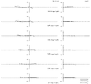
各数値実施例において、全体諸元中のfは焦点距離、FnoはFナンバー、2ωは画角を示す。また、レンズ諸元中の番号は物体側からのレンズの面番号、Rはレンズ面の曲率半径、Dはレンズ面間隔、ndはd線の屈折率、νdはd線のアッベ数を示す。また、Bfはバックフォーカスを示す。図中のd線、g線、C線はそれぞれの波長に対する収差であり、ΔSはサジタル像面、ΔMはメリジオナル像面を示す。 In each numerical example, f in the overall specifications indicates a focal length, Fno indicates an F number, and 2ω indicates an angle of view. The numbers in the lens specifications are the surface number of the lens from the object side, R is the radius of curvature of the lens surface, D is the distance between the lens surfaces, nd is the refractive index of the d-line, and νd is the Abbe number of the d-line. Bf represents back focus. In the drawing, d-line, g-line, and C-line are aberrations with respect to respective wavelengths, ΔS indicates a sagittal image plane, and ΔM indicates a meridional image plane.
各実施例の変倍結像光学系は条件式(1)から(6)のすべてを満たしている。
各実施例の変倍結像光学系において、非球面レンズを第1レンズ群内に少なくとも2枚、第4レンズ群内に1枚、それぞれ配置している。
これらの非球面レンズによって歪曲収差及びコマ収差に加え、像面湾曲及び非点収差をさらに良好に制御し、補正することが可能である。
さらに、非球面レンズの効果的な使用によって光学系を構成するレンズエレメントの枚数を削減することが可能となり、光学系全体の小型化に寄与する。
各実施例の非球面レンズの非球面形状は次式で定義される。
The variable magnification imaging optical system of each embodiment satisfies all of the conditional expressions (1) to (6).
In the variable magnification imaging optical system of each embodiment, at least two aspheric lenses are disposed in the first lens group, and one is disposed in the fourth lens group.
With these aspheric lenses, in addition to distortion and coma, field curvature and astigmatism can be controlled and corrected more satisfactorily.
Furthermore, the effective use of the aspheric lens makes it possible to reduce the number of lens elements constituting the optical system, contributing to the miniaturization of the entire optical system.
The aspheric shape of the aspheric lens of each embodiment is defined by the following equation.

各実施例中に示した変倍結像光学系は多いもので14枚、少ないものでは13枚のレンズエレメントによって構成されている。各実施例の変倍結像光学系はいずれも1.8を超える変倍比を実現している。 The variable magnification imaging optical system shown in each embodiment is composed of a large number of 14 lens elements and a small number of 13 lens elements. Each of the variable magnification imaging optical systems of the embodiments achieves a variable magnification ratio exceeding 1.8.
(数値実施例1)
![]()
![]()
(数値実施例2)
![]()
![]()
(数値実施例3)
![]()
![]()
(数値実施例4)
![]()
![]()
(数値実施例5)
![]()
![]()
(数値実施例6)
![]()
![]()
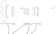
L1 第1レンズ群
L2 第2レンズ群
L3 第3レンズ群
L4 第4レンズ群
SP 開口絞り
IP 像面
d d線
g g線
C C線
ΔS サジタル像面
ΔM メリジオナル像面
L1 1st lens group L2 2nd lens group L3 3rd lens group L4 4th lens group SP Aperture stop IP Image surface d d line g g line C C line ΔS Sagittal image surface ΔM Meridional image surface
Claims (3)
負の屈折力を持つ第1レンズ群と、
正の屈折力を持つ第2レンズ群と、
負の屈折力を持つ第3レンズ群と、
正の屈折力を持つ第4レンズ群とからなり、
広角端から望遠端への変倍に際して、隣接する各レンズ群同士の間隔が変化し、少なくとも該第1レンズ群、該第2レンズ群、及び該第4レンズ群を光軸に沿う方向へ移動させ、
該第2レンズ群から該第4レンズ群までの合成屈折力は変倍全域において常に正であり、
前記第1レンズ群は最も物体側から順に少なくとも2枚の負レンズを備えるとともに、
最も物体側のレンズは負の屈折力を備え、物体側に凸のメニスカス形状であり、少なくとも1つのレンズ面が非球面形状であって、
前記第4レンズ群中には屈折力符号の異なるレンズエレメントの貼り合わせより構成される少なくとも1つの接合レンズLcを備え、
以下の条件式を満足することを特徴とする変倍結像光学系。
(1)0.55<|βwr|<0.75
(2)2.6<β2w/β4w<8.5
(3)3.5<νp/νn
ただし、
βwr:第2レンズ群から第4レンズ群の広角端かつ無限遠結像状態における合成結像倍率
νp:第4レンズ群の何れかの接合レンズLcを構成する正レンズのd線(波長587.6nm)基準のアッベ数
νn:第4レンズ群の何れかの接合レンズLcを構成する負レンズのd線(波長587.6nm)基準のアッベ数
βiw:第iレンズ群の広角端かつ無限遠結像状態における結像倍率 From the object side,
A first lens group having negative refractive power;
A second lens group having positive refractive power;
A third lens group having negative refractive power;
It consists of a fourth lens group having positive refractive power,
During zooming from the wide-angle end to the telephoto end, the distance between adjacent lens groups changes, and at least the first lens group, the second lens group, and the fourth lens group move in a direction along the optical axis. Let
The combined refractive power from the second lens group to the fourth lens group is always positive over the entire zoom range,
The first lens group includes at least two negative lenses in order from the most object side,
The most object-side lens has negative refractive power, has a meniscus shape convex toward the object side, and at least one lens surface has an aspheric shape,
The fourth lens group includes at least one cemented lens Lc configured by bonding lens elements having different refractive power codes,
A variable magnification imaging optical system characterized by satisfying the following conditional expression:
(1) 0.55 <| βwr | <0.75
(2) 2.6 <β2w / β4w <8.5
(3) 3.5 <νp / νn
However,
βwr: Composite imaging magnification νp at the wide-angle end and infinity imaging state from the second lens group to the fourth lens group: d line (wavelength 587...) of the positive lens constituting any one of the cemented lenses Lc of the fourth lens group 6 nm) Reference Abbe number νn: d-line (wavelength 587.6 nm) reference Abbe number βiw of the negative lens constituting any cemented lens Lc of the fourth lens group: Wide angle end and infinite connection of the i-th lens group Imaging magnification in the image state
(4)30<|RLc/(ndLcn−ndLcp)|<50
(5)ndLcp/ndLcn<0.80
ただし、
RLc:第4レンズ群中の何れかの接合レンズLcにおける接合面の曲率半径
ndLcp:第4レンズ群中の何れかの接合レンズLcを構成する正レンズのd線(波長587.6nm)の屈折率
ndLcn:第4レンズ群中の何れかの接合レンズLcを構成する負レンズのd線(波長587.6nm)の屈折率 The variable magnification imaging optical system according to claim 1, wherein the following conditional expression is satisfied with respect to the cemented lens Lc.
(4) 30 <| RLc / (ndLcn−ndLcp) | <50
(5) ndLcp / ndLcn <0.80
However,
RLc: curvature radius of the cemented surface of any cemented lens Lc in the fourth lens group ndLcp: refraction of d-line (wavelength 587.6 nm) of the positive lens constituting any cemented lens Lc in the fourth lens group Index ndLcn: the refractive index of the d-line (wavelength 587.6 nm) of the negative lens constituting any one of the cemented lenses Lc in the fourth lens group
(6)3.00<bfw/fw<5.00
ただし、
bfw:広角端かつ無限遠結像状態におけるバックフォーカス
fw:広角端かつ無限遠結像状態における光学系全体の合成焦点距離 The variable magnification imaging optical system according to claim 1, wherein the following conditional expression is satisfied.
(6) 3.00 <bfw / fw <5.00
However,
bfw: Back focus at the wide-angle end and infinity imaging state fw: Composite focal length of the entire optical system at the wide-angle end and infinity imaging state
Priority Applications (1)
| Application Number | Priority Date | Filing Date | Title |
|---|---|---|---|
| JP2009091645A JP5395495B2 (en) | 2009-04-06 | 2009-04-06 | Variable magnification optical system |
Applications Claiming Priority (1)
| Application Number | Priority Date | Filing Date | Title |
|---|---|---|---|
| JP2009091645A JP5395495B2 (en) | 2009-04-06 | 2009-04-06 | Variable magnification optical system |
Publications (3)
| Publication Number | Publication Date |
|---|---|
| JP2010243737A JP2010243737A (en) | 2010-10-28 |
| JP2010243737A5 JP2010243737A5 (en) | 2012-05-24 |
| JP5395495B2 true JP5395495B2 (en) | 2014-01-22 |
Family
ID=43096822
Family Applications (1)
| Application Number | Title | Priority Date | Filing Date |
|---|---|---|---|
| JP2009091645A Active JP5395495B2 (en) | 2009-04-06 | 2009-04-06 | Variable magnification optical system |
Country Status (1)
| Country | Link |
|---|---|
| JP (1) | JP5395495B2 (en) |
Families Citing this family (7)
| Publication number | Priority date | Publication date | Assignee | Title |
|---|---|---|---|---|
| JP6207374B2 (en) * | 2013-12-12 | 2017-10-04 | キヤノン株式会社 | Optical system and imaging apparatus having the same |
| JP2016126281A (en) * | 2015-01-08 | 2016-07-11 | 株式会社タムロン | Wide-angle zoom lens and imaging apparatus |
| JP6540052B2 (en) * | 2015-01-29 | 2019-07-10 | 株式会社シグマ | Imaging optical system |
| JP6798296B2 (en) * | 2016-12-09 | 2020-12-09 | 株式会社リコー | Variable magnification optical system |
| JP2019003198A (en) * | 2018-08-01 | 2019-01-10 | 株式会社ニコン | Zoom lens and imaging apparatus |
| CN114035308B (en) * | 2021-11-23 | 2023-09-19 | 中国航空工业集团公司洛阳电光设备研究所 | Large-relative-aperture compact uncooled infrared zoom monitoring lens |
| CN114488485B (en) * | 2022-02-14 | 2023-07-07 | 合肥埃科光电科技股份有限公司 | Large-target-surface wide-angle low-distortion industrial lens with f22mm |
Family Cites Families (5)
| Publication number | Priority date | Publication date | Assignee | Title |
|---|---|---|---|---|
| JPH04235514A (en) * | 1991-01-11 | 1992-08-24 | Nikon Corp | Super-wide angle zoom lens |
| JPH09113808A (en) * | 1995-10-20 | 1997-05-02 | Nikon Corp | Zoom lens |
| JP2005106878A (en) * | 2003-09-29 | 2005-04-21 | Sigma Corp | Super-wide angle lens system |
| JP4819414B2 (en) * | 2004-06-25 | 2011-11-24 | キヤノン株式会社 | Zoom lens and imaging apparatus having the same |
| JP5074790B2 (en) * | 2007-03-07 | 2012-11-14 | キヤノン株式会社 | Zoom lens and imaging apparatus having the same |
-
2009
- 2009-04-06 JP JP2009091645A patent/JP5395495B2/en active Active
Also Published As
| Publication number | Publication date |
|---|---|
| JP2010243737A (en) | 2010-10-28 |
Similar Documents
| Publication | Publication Date | Title |
|---|---|---|
| JP4881035B2 (en) | Zoom lens and imaging apparatus having the same | |
| JP5197242B2 (en) | Zoom lens and imaging apparatus having the same | |
| US7715121B2 (en) | Optical system and optical apparatus including optical system | |
| JP4366110B2 (en) | Zoom lens and optical apparatus having the same | |
| JP4532916B2 (en) | Zoom lens and imaging apparatus having the same | |
| JP5309553B2 (en) | Zoom lens and optical apparatus provided with the zoom lens | |
| JP2006285019A (en) | Zoom lens and imaging apparatus equipped with the same | |
| JP5395495B2 (en) | Variable magnification optical system | |
| JP5601586B2 (en) | Optical system and optical equipment | |
| JP4829629B2 (en) | Zoom lens and imaging apparatus having the same | |
| US8248703B2 (en) | Zoom lens and optical apparatus having the zoom lens | |
| JP6253379B2 (en) | Optical system and imaging apparatus having the same | |
| JP5151635B2 (en) | PHOTOGRAPHIC LENS, OPTICAL DEVICE EQUIPPED WITH THIS PHOTOGRAPHIC LENS, AND IMAGE-FORMING METHOD | |
| JP2006337793A (en) | Zoom lens and imaging apparatus using same | |
| JP5919518B2 (en) | Zoom lens system, imaging device and camera | |
| JP6938841B2 (en) | Zoom lens and optical equipment | |
| JP5858761B2 (en) | Zoom lens and imaging apparatus having the same | |
| JP6164894B2 (en) | Zoom lens and imaging apparatus having the same | |
| JP2006071698A (en) | Wide-angle zoom lens | |
| JP5082486B2 (en) | Zoom lens and optical apparatus having the same | |
| JP4799210B2 (en) | Zoom lens system and camera system including the same | |
| JP5058634B2 (en) | Zoom lens and imaging apparatus having the same | |
| JP5987543B2 (en) | Zoom lens, optical device | |
| JP5386868B2 (en) | Zoom lens, optical equipment | |
| JP4715141B2 (en) | Front teleconverter lens |
Legal Events
| Date | Code | Title | Description |
|---|---|---|---|
| A521 | Request for written amendment filed |
Free format text: JAPANESE INTERMEDIATE CODE: A523 Effective date: 20120404 |
|
| A621 | Written request for application examination |
Free format text: JAPANESE INTERMEDIATE CODE: A621 Effective date: 20120404 |
|
| A977 | Report on retrieval |
Free format text: JAPANESE INTERMEDIATE CODE: A971007 Effective date: 20130614 |
|
| A131 | Notification of reasons for refusal |
Free format text: JAPANESE INTERMEDIATE CODE: A131 Effective date: 20130709 |
|
| A521 | Request for written amendment filed |
Free format text: JAPANESE INTERMEDIATE CODE: A523 Effective date: 20130722 |
|
| TRDD | Decision of grant or rejection written | ||
| A01 | Written decision to grant a patent or to grant a registration (utility model) |
Free format text: JAPANESE INTERMEDIATE CODE: A01 Effective date: 20131008 |
|
| A61 | First payment of annual fees (during grant procedure) |
Free format text: JAPANESE INTERMEDIATE CODE: A61 Effective date: 20131018 |
|
| R150 | Certificate of patent or registration of utility model |
Ref document number: 5395495 Country of ref document: JP Free format text: JAPANESE INTERMEDIATE CODE: R150 Free format text: JAPANESE INTERMEDIATE CODE: R150 |
|
| R250 | Receipt of annual fees |
Free format text: JAPANESE INTERMEDIATE CODE: R250 |
|
| R250 | Receipt of annual fees |
Free format text: JAPANESE INTERMEDIATE CODE: R250 |
|
| R250 | Receipt of annual fees |
Free format text: JAPANESE INTERMEDIATE CODE: R250 |
|
| R250 | Receipt of annual fees |
Free format text: JAPANESE INTERMEDIATE CODE: R250 |
|
| R250 | Receipt of annual fees |
Free format text: JAPANESE INTERMEDIATE CODE: R250 |
|
| R250 | Receipt of annual fees |
Free format text: JAPANESE INTERMEDIATE CODE: R250 |
|
| R250 | Receipt of annual fees |
Free format text: JAPANESE INTERMEDIATE CODE: R250 |
|
| R250 | Receipt of annual fees |
Free format text: JAPANESE INTERMEDIATE CODE: R250 |