JP4635782B2 - Nursing aid - Google Patents
Nursing aid Download PDFInfo
- Publication number
- JP4635782B2 JP4635782B2 JP2005241815A JP2005241815A JP4635782B2 JP 4635782 B2 JP4635782 B2 JP 4635782B2 JP 2005241815 A JP2005241815 A JP 2005241815A JP 2005241815 A JP2005241815 A JP 2005241815A JP 4635782 B2 JP4635782 B2 JP 4635782B2
- Authority
- JP
- Japan
- Prior art keywords
- holding cover
- holding
- abutment
- leg
- present
- Prior art date
- Legal status (The legal status is an assumption and is not a legal conclusion. Google has not performed a legal analysis and makes no representation as to the accuracy of the status listed.)
- Active
Links
- 230000000474 nursing effect Effects 0.000 title description 2
- 239000004744 fabric Substances 0.000 claims description 18
- 239000000463 material Substances 0.000 claims description 8
- 210000002414 leg Anatomy 0.000 description 20
- 230000013872 defecation Effects 0.000 description 8
- 230000036544 posture Effects 0.000 description 7
- 230000008602 contraction Effects 0.000 description 3
- 230000009286 beneficial effect Effects 0.000 description 2
- 238000009958 sewing Methods 0.000 description 2
- 229920003002 synthetic resin Polymers 0.000 description 2
- 239000000057 synthetic resin Substances 0.000 description 2
- 206010010774 Constipation Diseases 0.000 description 1
- 206010028980 Neoplasm Diseases 0.000 description 1
- 208000004210 Pressure Ulcer Diseases 0.000 description 1
- 101700004678 SLIT3 Proteins 0.000 description 1
- 102100027339 Slit homolog 3 protein Human genes 0.000 description 1
- 210000000436 anus Anatomy 0.000 description 1
- 238000005452 bending Methods 0.000 description 1
- 201000011510 cancer Diseases 0.000 description 1
- 238000007796 conventional method Methods 0.000 description 1
- 201000010099 disease Diseases 0.000 description 1
- 208000037265 diseases, disorders, signs and symptoms Diseases 0.000 description 1
- 230000000694 effects Effects 0.000 description 1
- 239000006260 foam Substances 0.000 description 1
- 210000003127 knee Anatomy 0.000 description 1
- 230000003340 mental effect Effects 0.000 description 1
- 230000035699 permeability Effects 0.000 description 1
- 230000002787 reinforcement Effects 0.000 description 1
- 230000003014 reinforcing effect Effects 0.000 description 1
- 230000007958 sleep Effects 0.000 description 1
- 210000004243 sweat Anatomy 0.000 description 1
- 230000007306 turnover Effects 0.000 description 1
- 239000002023 wood Substances 0.000 description 1
Images


Description
この発明は、病人介護の場合に使用し、患者の体位置・姿勢を容易に安定化させるための介護補助具に関する。 The present invention relates to a care assisting tool for use in the care of a sick person to easily stabilize the body position / posture of a patient.
従来より、寝たきりの患者は自分で体を動かすことが困難なため、ナースや付添人等の介護者の助力が必要であり、この介護者に助けられて姿勢を変えたり、体表面の拭き取りや排便の処理等を行っている。しかし、このような場合において介護を容易にするための補助用具は現在のところ見当たらない。 Conventionally, bedridden patients have difficulty in moving their bodies themselves, so the caregivers such as nurses and attendants are required to assist, and this caregiver can help change postures, wipe the body surface, and so on. We are processing defecation. However, there are currently no auxiliary tools for facilitating care in such cases.
全国には末期ガンその他の疾病のために、自力で体を動かすことの困難ないわゆる寝たきりの患者が相当数存在している。これらの患者は寝たきりのため、自分では寝返りもままならず、また背中に汗をかくためその拭き取りや、排便など介護者の助けを借りてこれらのことを行わねばならない。とりわけ、排便時の助力は必須である。この排便時は、一般的には体を動かして横向きに寝た状態にし、介護者が排便の助力を行うが、腰部に体重がかかり、しかもクッション性を有するベッドの上で行うために肛門が開きにくく、患者も介護者も難儀をしているのが現状である。さらに、横向きに寝た状態は双方の脚が上下に位置するので、体力の衰えた患者にとってその姿勢保持が難しい。
本発明は、以上のような従来からの寝たきり患者の介護に関わる課題を解決するために発明されたもので、横向きに寝たときの患者の脚位置保持を行うことにより姿勢の安定が保たれて、患者と介護者双方にとって有益なる補助具を提供することを目的として開発されたものである。There are a number of so-called bedridden patients who are unable to move themselves on their own due to terminal cancer and other diseases. Because these patients are bedridden, they cannot turn over themselves, and they must do this with the help of a caregiver, such as wiping to sweat back and defecation. In particular, assistance during defecation is essential. During this defecation, the body is generally moved to the side, and the caregiver assists with the defecation, but the anus is placed on the bed with weight on the waist and cushioning. The current situation is that it is difficult to open and both patients and caregivers have difficulty. Furthermore, since both legs are positioned up and down in a state of lying down sideways, it is difficult for a patient with weak physical strength to maintain its posture.
The present invention was invented in order to solve the above-mentioned problems related to the care of bedridden patients, and the posture of the patient can be kept stable by maintaining the leg position of the patient when lying on the side. It was developed for the purpose of providing assistive devices that are beneficial to both patients and caregivers.
課題を解決する手段として本発明は、支台と保持カバーを着脱係止可能に設けてその主要部を構成した。すなわち、所定高さを有し内部に空隙部を有する支台を設け、一方、柔軟性を有する素材にて保持カバーを設けるとともに、該保持カバー端部間の係止着脱手段と保持カバーの支台に対する係止着脱手段を設ける。本発明は以上の構成よりなる介護補助具である。 As means for solving the problems, the present invention is configured such that the abutment and the holding cover are provided so as to be detachably lockable, and the main part thereof is configured. That is, an abutment having a predetermined height and having a gap inside is provided, while a holding cover is provided with a flexible material, and the holding / removing means between the holding cover end portions and the holding cover are supported. Locking attachment / detachment means for the base is provided. The present invention is a care aid having the above-described configuration.
本発明によれば、患者の脚位置保持が容易となり、かつ体重の分散が行われるため、従来困難であった患者の背中の拭き取り、排便補助、おむつ替えなどの諸作業を介護者一人にて容易に行うことができ、患者と介護者双方にとって有益なる介護用の補助具を提供することができる。 According to the present invention, the patient's leg position can be easily maintained and weight distribution is performed, so that the caregiver can perform various tasks such as wiping the patient's back, assisting defecation, and changing diapers, which have been difficult in the past. It is possible to provide a nursing aid that can be easily performed and is beneficial to both the patient and the caregiver.
以下、本発明の実施形態について説明する。
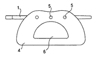
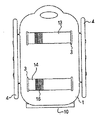
図1〜図3は本発明の支台を示すものである。図において、1は木製の支板で、略長方形の板体であり、一方の短辺をやや突出させてこの突出部に近接して楕円孔による取っ手孔2が設けられ、該支板の四隅近傍には長穴状のスリット3が穿設される。
支板の長辺側面はやや突出し、この突出部各々に脚板4がピン5にて固定される。
この脚板は変形台形状の木板であり、中央に側孔6が形成され、上部適所に貫通孔(図示略)を有している。また支板側面から内方に向けて同径の穴が穿設され、この貫通孔と穴とを一致させて、段部を有する円柱状のピンが嵌入固着し、支板と脚板とを固定している。なお、脚板下面は水平面であるが上部には湾曲凹部を有し、支板における取っ手孔と反対側の端部上下面はやや斜方に削り取られている。7は支板と脚板に固着される細長棒状の補強部材である。
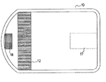
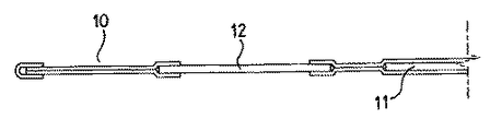
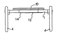
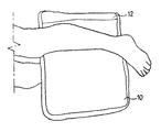
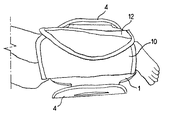
図4〜図6は本発明の保持カバー10を示すものである。この保持カバーは2枚の布を縫合して略長方形状に形成され、一方の短辺は曲線状に形成される。この保持カバーの周囲は別布にて縁取り縫合され、中央部分には板状の軟質発泡合成樹脂による緩衝材11が内包され、また曲線状の短辺に近接して伸縮布12が位置している。
この伸縮布は、ニット織りにて特定方向の伸縮度は高く、その特定方向と直角方向の伸縮度は低いという特徴を有している。この伸縮布は保持カバーの長辺間に長方形状に位置するが、その編み方によりこの配置において長方形長辺間方向には少しの伸縮であるが短辺間方向には大きな伸縮性を有している。なお、この伸縮布部分は袋状ではなく、この伸縮布を挟んで左右に2枚縫合部分が位置する。13〜14は対向して位置する保持ベルトで小長方形布片であり、その一端が保持カバー表面に縫着され、一方の面には面ファスナー15〜16が縫着される。この面ファスナーは一方は保持ベルト表面に、他方は保持ベルト裏面に設けられ、従って保持ベルト13と14は互いに係止可能である。また、この保持ベルト縫着は保持カバーの上下2枚の布体および前記緩衝材を共に縫着している。
17は保持カバー表面に縫着される面ファスナー、18は保持カバー裏面に縫着される面ファスナーであり、互いに係止可能である。Hereinafter, embodiments of the present invention will be described.
1 to 3 show an abutment of the present invention. In the figure, reference numeral 1 denotes a wooden support plate, which is a substantially rectangular plate body. One of the short sides protrudes slightly and a handle hole 2 by an elliptical hole is provided in the vicinity of the protruding portion. In the vicinity, a
The long side surface of the support plate slightly protrudes, and the
The leg plate is a deformed trapezoidal wooden plate, and a
4 to 6 show the
This stretchable fabric has a feature that it is knit-woven and has a high degree of stretch in a specific direction and a low degree of stretch in a direction perpendicular to the specific direction. This stretchable cloth is located in a rectangular shape between the long sides of the holding cover, but depending on how it is knitted, this arrangement has a slight stretch in the direction between the long sides of the rectangle, but has a large stretch in the direction between the short sides. ing. The stretchable cloth portion is not bag-shaped, and two stitched portions are located on the left and right sides of the stretchable cloth.
本発明の使用に際しては、まず保持カバーの保持ベルトをスリットに挿入し、支板下面にて対向する保持ベルトを重ね合わせて係止させる。この保持ベルトには既述のように面ファスナーが所定個所に縫着されているので、この面ファスナーが互いに密着し係止される。次ぎに、保持カバーを開いた状態にしてから、仰向けに寝ている患者の脚を少し開き、一方の脚に支台をかぶせる。次ぎに患者を横向きにして他方の脚を、支台上に開いて置かれた保持カバーの上に載せる。そしてその脚をくるむように保持カバーを脚に巻きつけ、保持カバーの面ファスナー17と18を密着させる。これにより強力な密着力が生じて、この保持カバーは患者の脚にしっかりと巻き付き、患者の上方の脚位置が定まることとなる。従って、患者が横向きに寝ても脚位置が定まっているためにその姿勢保持が容易となる。さらに、下方の脚は支台内に、上方の脚は支台上に位置するために体重の一部はこの支台上にかかるため、体重の分散が行われて腰部への負担が軽減され、おむつ換えや排便処理などの作業を容易に行うことができる。
本発明の保持カバーには緩衝材を設けており、使用時は支板と患者の足の間にこの緩衝材が位置することとなるため、ソフトな感触が得られ、また支板と足の温度差による感覚を和らげることができる。また、伸縮布を用いており、この伸縮布は前記のようにこの伸縮布の長辺間方向つまり保持カバーの短辺間方向の伸縮よりも長辺間方向の伸縮度が大きいという特徴がある。従って、例えば支板に対して膝を曲げるなど足をやや斜方に位置させても、この伸縮布の伸縮にて伸縮布の中ほどを膨らませて違和感なく足をくるんで保持させることができる。また、保持カバー短辺間方向の伸縮度は大きくないため、足をしっかりとくるんで保持することができる。例えば、保持カバー短辺間方向の伸縮度も大きくすると、カバー端部間の係止時において該カバーを引張した場合に、足に対する押圧感が生じて患者に負担となるが、上記のようにこの方向の伸縮度は高くないのでこれを防止することができる。なお、この伸縮布は従来技術で製作可能である。
脚板は側孔を有しており、支台の軽量化とともに通気性を高めている。なお本例について、取っ手孔2は支台を運ぶ際の取っ手として利用するために設けたものである。
本例では支台を正面視コ字形としたが、これに限らず四角枠型など種々の形状を用いることができる。本例の支台の一方の端部は少し削った斜面を有するが、これは開いた脚の傾斜に沿うよう考慮したものである。本例の支台は木製であるが、合成樹脂等他の素材を用いてもよく、適度な曲面を用いてデザイン的に工夫して製作することも可能である。なお、本例では係止手段として面ファスナーを用いたが、スナップ、ホックその他の係止手段を用いてもよい。In using the present invention, first, the holding belt of the holding cover is inserted into the slit, and the holding belts facing each other on the lower surface of the support plate are overlapped and locked. Since the hook-and-loop fastener is sewn to the holding belt at a predetermined position as described above, the hook-and-loop fasteners are brought into close contact with each other and locked. Next, with the holding cover open, the patient's leg lying on his back is slightly opened, and an abutment is placed on one leg. The patient is then turned sideways and the other leg is placed on a holding cover placed open on the abutment. Then, the holding cover is wound around the leg so as to wrap the leg, and the
The holding cover of the present invention is provided with a cushioning material, and since this cushioning material is positioned between the support plate and the patient's foot when in use, a soft feel is obtained, and the support plate and the foot You can relieve the sense of temperature difference. Further, an elastic cloth is used, and as described above, the elastic cloth has a feature that the degree of expansion in the direction between the long sides is larger than the expansion in the direction between the long sides of the elastic cloth, that is, the direction between the short sides of the holding cover. . Accordingly, even if the foot is positioned slightly obliquely, for example, by bending the knee with respect to the support plate, the middle of the elastic fabric can be inflated by the expansion and contraction of the elastic fabric, and the foot can be wrapped and held without a sense of incongruity. Further, since the degree of expansion and contraction in the direction between the short sides of the holding cover is not large, the foot can be securely wrapped and held. For example, if the degree of expansion and contraction in the direction between the short sides of the holding cover is increased, when the cover is pulled between the cover end portions, a feeling of pressing against the foot is generated and a burden is imposed on the patient. Since the degree of stretch in this direction is not high, this can be prevented. This stretchable fabric can be manufactured by conventional techniques.
The leg plate has a side hole to reduce the weight of the abutment and increase the air permeability. In this example, the handle hole 2 is provided for use as a handle when carrying the abutment.
In this example, the abutment has a U-shape when viewed from the front. However, the shape is not limited to this, and various shapes such as a square frame type can be used. One end of the abutment of this example has a slightly cut slope, which is taken into account along the slope of the open leg. The abutment in this example is made of wood, but other materials such as synthetic resin may be used, and it is also possible to devise a design using an appropriate curved surface. In this example, a hook-and-loop fastener is used as the locking means, but a snap, hook or other locking means may be used.
本発明の概要については既述したが、本発明は所定高さの位置に患者の脚を保持できるところにその特徴がある。疼痛が激しい患者などはその痛みのため自分で身体を動かすことが困難であり、寝返りなどは介護者の助力が必要である。また運動不足となるため、便秘しがちになり、排便も自分で行うことはできない。体力が弱っているため、横向きに寝た姿勢の保持は自力では難しい。そのため、一人が身体を支え、他の一人が必要な作業を行うなど二人がかりで介護しなければならない。また、横向きに寝た状態では体重の多くは腰部にかかるため、おむつ替えや排便の作業が困難であった。
しかるに本発明によれば、体重分散が行われ脚位置が定まり、姿勢保持も容易となるため、上記の作業がし易くなり、かつ一人の介護者にて作業を行うことができるのである。
また、側臥位置が容易にとれるため、床ずれ防止にも有効であり、患者のメンタルケア効果も大である。この発明によって、多くの寝たきり患者とその介護者の双方に福音をもたらす有益なる用具を得ることができ、多くの患者に希望を与えることが可能となるものである。Although the outline of the present invention has already been described, the present invention is characterized in that the patient's leg can be held at a predetermined height. Patients with severe pain have difficulty in moving their body because of the pain, and caregivers need assistance when turning over. Also, due to lack of exercise, constipation tends to occur, and defecation cannot be performed by oneself. Since the physical strength is weak, it is difficult to hold a lying-down posture on its own. For this reason, one person must support the body and the other person must perform the necessary work. Also, when lying on its side, most of the weight falls on the lower back, making it difficult to change diapers and defecate.
However, according to the present invention, the weight distribution is performed, the leg position is determined, and the posture can be easily maintained. Therefore, the above work is facilitated, and the work can be performed by a single caregiver.
In addition, since the scissor position can be easily taken, it is effective in preventing bedsores and has a great mental care effect for the patient. According to the present invention, it is possible to obtain useful tools that bring the gospel to both bedridden patients and their caregivers, and to give hope to many patients.
1 支板
2 取っ手孔
3 スリット
4 脚板
5 ピン
6 側孔
7 補強部材
10 保持カバー
11 緩衝材
12 伸縮布
13 保持ベルト
14 保持ベルト
15 面ファスナー
16 面ファスナー
17 面ファスナー
18 面ファスナー
19 保持ベルト縫着部
20 保持ベルト縫着部DESCRIPTION OF SYMBOLS 1 Support plate 2
Claims (1)
Priority Applications (1)
| Application Number | Priority Date | Filing Date | Title |
|---|---|---|---|
| JP2005241815A JP4635782B2 (en) | 2005-07-26 | 2005-07-26 | Nursing aid |
Applications Claiming Priority (1)
| Application Number | Priority Date | Filing Date | Title |
|---|---|---|---|
| JP2005241815A JP4635782B2 (en) | 2005-07-26 | 2005-07-26 | Nursing aid |
Publications (2)
| Publication Number | Publication Date |
|---|---|
| JP2007029692A JP2007029692A (en) | 2007-02-08 |
| JP4635782B2 true JP4635782B2 (en) | 2011-02-23 |
Family
ID=37789624
Family Applications (1)
| Application Number | Title | Priority Date | Filing Date |
|---|---|---|---|
| JP2005241815A Active JP4635782B2 (en) | 2005-07-26 | 2005-07-26 | Nursing aid |
Country Status (1)
| Country | Link |
|---|---|
| JP (1) | JP4635782B2 (en) |
Citations (6)
| Publication number | Priority date | Publication date | Assignee | Title |
|---|---|---|---|---|
| JPS6055944A (en) * | 1983-09-07 | 1985-04-01 | 大衛株式会社 | Partial restricting band and leg restricting band of human body for medical use |
| JPH0638967U (en) * | 1992-10-29 | 1994-05-24 | 慶孝 尾坪 | Pedestal |
| JPH09108254A (en) * | 1995-03-07 | 1997-04-28 | Yomisu:Kk | Violent behavior prevention tool in changing diaper |
| JP2003153965A (en) * | 2002-10-31 | 2003-05-27 | Akira Kanai | Nursing care assisting device |
| JP2004121566A (en) * | 2002-10-03 | 2004-04-22 | Kiyoko Miyazaki | Foot rest pillow |
| JP2005021625A (en) * | 2003-07-04 | 2005-01-27 | Toshiaki Hisatake | Tool for exchanging diaper |
-
2005
- 2005-07-26 JP JP2005241815A patent/JP4635782B2/en active Active
Patent Citations (6)
| Publication number | Priority date | Publication date | Assignee | Title |
|---|---|---|---|---|
| JPS6055944A (en) * | 1983-09-07 | 1985-04-01 | 大衛株式会社 | Partial restricting band and leg restricting band of human body for medical use |
| JPH0638967U (en) * | 1992-10-29 | 1994-05-24 | 慶孝 尾坪 | Pedestal |
| JPH09108254A (en) * | 1995-03-07 | 1997-04-28 | Yomisu:Kk | Violent behavior prevention tool in changing diaper |
| JP2004121566A (en) * | 2002-10-03 | 2004-04-22 | Kiyoko Miyazaki | Foot rest pillow |
| JP2003153965A (en) * | 2002-10-31 | 2003-05-27 | Akira Kanai | Nursing care assisting device |
| JP2005021625A (en) * | 2003-07-04 | 2005-01-27 | Toshiaki Hisatake | Tool for exchanging diaper |
Also Published As
| Publication number | Publication date |
|---|---|
| JP2007029692A (en) | 2007-02-08 |
Similar Documents
| Publication | Publication Date | Title |
|---|---|---|
| US10786091B2 (en) | Infant stabilization and immobilization apparatus | |
| US7178877B2 (en) | Diaper changing restraint system | |
| US20080313812A1 (en) | Portable Infant Support Apparatus | |
| CA2792612C (en) | Orthopaedic foot support | |
| WO2004062340A2 (en) | Easily changeable absorbent panel for bed clothing | |
| US8607386B2 (en) | Infant positioning system and prone positioning apparatus therefor | |
| US3959832A (en) | Invalid hammock | |
| US6578210B2 (en) | Patient assistive device and lift system | |
| JP5552578B1 (en) | Pressure ulcer prevention supporter | |
| JP2018121656A (en) | Pet posture holding base | |
| JP4635782B2 (en) | Nursing aid | |
| WO2014073025A1 (en) | Carry assist instrument | |
| JP6695605B1 (en) | Nursing mat | |
| JP3878770B2 (en) | Abduction pillow | |
| JP2001104091A (en) | Elbow pad | |
| JP4936564B2 (en) | Nursing aid | |
| JP3089922U (en) | Articulated mattress | |
| JP3094169U (en) | Pressure ulcer prevention equipment | |
| JP2003153965A (en) | Nursing care assisting device | |
| JP6730758B1 (en) | Care equipment and care equipment set | |
| JP2580492B2 (en) | Spread leg holding type turnover aid | |
| JP2002028193A (en) | Posture stabilizing cushion for nursing | |
| JP3187691U (en) | Nursing pants | |
| JPH0718721U (en) | Mattress combined use futon | |
| IT202100005894U1 (en) | TILTING LEG SUPPORT DEVICE FOR BED-BED PATIENTS. |
Legal Events
| Date | Code | Title | Description |
|---|---|---|---|
| A621 | Written request for application examination |
Free format text: JAPANESE INTERMEDIATE CODE: A621 Effective date: 20071120 |
|
| A131 | Notification of reasons for refusal |
Free format text: JAPANESE INTERMEDIATE CODE: A131 Effective date: 20100622 |
|
| A977 | Report on retrieval |
Free format text: JAPANESE INTERMEDIATE CODE: A971007 Effective date: 20100624 |
|
| A521 | Request for written amendment filed |
Free format text: JAPANESE INTERMEDIATE CODE: A523 Effective date: 20100709 |
|
| A131 | Notification of reasons for refusal |
Free format text: JAPANESE INTERMEDIATE CODE: A131 Effective date: 20100824 |
|
| A521 | Request for written amendment filed |
Free format text: JAPANESE INTERMEDIATE CODE: A523 Effective date: 20100915 |
|
| TRDD | Decision of grant or rejection written | ||
| A01 | Written decision to grant a patent or to grant a registration (utility model) |
Free format text: JAPANESE INTERMEDIATE CODE: A01 Effective date: 20101102 |
|
| A01 | Written decision to grant a patent or to grant a registration (utility model) |
Free format text: JAPANESE INTERMEDIATE CODE: A01 |
|
| A61 | First payment of annual fees (during grant procedure) |
Free format text: JAPANESE INTERMEDIATE CODE: A61 Effective date: 20101108 |
|
| FPAY | Renewal fee payment (event date is renewal date of database) |
Free format text: PAYMENT UNTIL: 20131203 Year of fee payment: 3 |
|
| R150 | Certificate of patent or registration of utility model |
Ref document number: 4635782 Country of ref document: JP Free format text: JAPANESE INTERMEDIATE CODE: R150 Free format text: JAPANESE INTERMEDIATE CODE: R150 |
|
| R250 | Receipt of annual fees |
Free format text: JAPANESE INTERMEDIATE CODE: R250 |
|
| R250 | Receipt of annual fees |
Free format text: JAPANESE INTERMEDIATE CODE: R250 |
|
| R250 | Receipt of annual fees |
Free format text: JAPANESE INTERMEDIATE CODE: R250 |
|
| R250 | Receipt of annual fees |
Free format text: JAPANESE INTERMEDIATE CODE: R250 |
|
| R250 | Receipt of annual fees |
Free format text: JAPANESE INTERMEDIATE CODE: R250 |
|
| R250 | Receipt of annual fees |
Free format text: JAPANESE INTERMEDIATE CODE: R250 |
|
| R250 | Receipt of annual fees |
Free format text: JAPANESE INTERMEDIATE CODE: R250 |
|
| R250 | Receipt of annual fees |
Free format text: JAPANESE INTERMEDIATE CODE: R250 |
|
| R250 | Receipt of annual fees |
Free format text: JAPANESE INTERMEDIATE CODE: R250 |
|
| R250 | Receipt of annual fees |
Free format text: JAPANESE INTERMEDIATE CODE: R250 |
|
| R250 | Receipt of annual fees |
Free format text: JAPANESE INTERMEDIATE CODE: R250 |