JP4635766B2 - binder - Google Patents
binder Download PDFInfo
- Publication number
- JP4635766B2 JP4635766B2 JP2005216314A JP2005216314A JP4635766B2 JP 4635766 B2 JP4635766 B2 JP 4635766B2 JP 2005216314 A JP2005216314 A JP 2005216314A JP 2005216314 A JP2005216314 A JP 2005216314A JP 4635766 B2 JP4635766 B2 JP 4635766B2
- Authority
- JP
- Japan
- Prior art keywords
- binder
- ring
- processing machine
- contact
- guide
- Prior art date
- Legal status (The legal status is an assumption and is not a legal conclusion. Google has not performed a legal analysis and makes no representation as to the accuracy of the status listed.)
- Active
Links
- 239000011230 binding agent Substances 0.000 title claims description 184
- 230000001105 regulatory effect Effects 0.000 claims description 7
- 230000002093 peripheral effect Effects 0.000 description 10
- 230000007246 mechanism Effects 0.000 description 5
- 208000026438 poor feeding Diseases 0.000 description 3
- 238000005452 bending Methods 0.000 description 2
- 230000008859 change Effects 0.000 description 2
- 230000008602 contraction Effects 0.000 description 2
- 230000008901 benefit Effects 0.000 description 1
- 210000000078 claw Anatomy 0.000 description 1
- 230000007613 environmental effect Effects 0.000 description 1
- 230000013011 mating Effects 0.000 description 1
- 239000002184 metal Substances 0.000 description 1
- 238000000034 method Methods 0.000 description 1
- 238000012986 modification Methods 0.000 description 1
- 230000004048 modification Effects 0.000 description 1
- 238000000465 moulding Methods 0.000 description 1
- 230000000149 penetrating effect Effects 0.000 description 1
- 230000008569 process Effects 0.000 description 1
Images


Classifications
-
- B—PERFORMING OPERATIONS; TRANSPORTING
- B42—BOOKBINDING; ALBUMS; FILES; SPECIAL PRINTED MATTER
- B42F—SHEETS TEMPORARILY ATTACHED TOGETHER; FILING APPLIANCES; FILE CARDS; INDEXING
- B42F13/00—Filing appliances with means for engaging perforations or slots
- B42F13/16—Filing appliances with means for engaging perforations or slots with claws or rings
- B42F13/20—Filing appliances with means for engaging perforations or slots with claws or rings pivotable about an axis or axes parallel to binding edges
- B42F13/22—Filing appliances with means for engaging perforations or slots with claws or rings pivotable about an axis or axes parallel to binding edges in two sections engaging each other when closed
- B42F13/26—Filing appliances with means for engaging perforations or slots with claws or rings pivotable about an axis or axes parallel to binding edges in two sections engaging each other when closed and locked when so engaged, e.g. snap-action
-
- B—PERFORMING OPERATIONS; TRANSPORTING
- B42—BOOKBINDING; ALBUMS; FILES; SPECIAL PRINTED MATTER
- B42B—PERMANENTLY ATTACHING TOGETHER SHEETS, QUIRES OR SIGNATURES OR PERMANENTLY ATTACHING OBJECTS THERETO
- B42B5/00—Permanently attaching together sheets, quires or signatures otherwise than by stitching
- B42B5/08—Permanently attaching together sheets, quires or signatures otherwise than by stitching by finger, claw or ring-like elements passing through the sheets, quires or signatures
-
- B—PERFORMING OPERATIONS; TRANSPORTING
- B42—BOOKBINDING; ALBUMS; FILES; SPECIAL PRINTED MATTER
- B42P—INDEXING SCHEME RELATING TO BOOKS, FILING APPLIANCES OR THE LIKE
- B42P2241/00—Parts, details or accessories for books or filing appliances
- B42P2241/24—Means for facilitating stacking or packaging
Description
この発明は、書類等の冊子を綴じるバインダーに関するものであり、特に、自動バインド処理装置にて装着することを主目的としたバインダーに関するものである。 The present invention relates to a binder for binding a booklet such as a document, and more particularly to a binder mainly intended to be mounted by an automatic binding processing apparatus.
市販のルーズリーフ用紙や、多穴ペーパーパンチにて穿孔処理した書類を綴じるためのプラスチック製バインダーが知られている(特許文献1参照)。このバインダーは、背骨部の両側に多数の1/2リング部を一定間隔で配列したもので、背骨部自体が二つ割りのヒンジとなっている一体成形品である。背骨部を挟んで一方の列の1/2リング部の先端には球形突起が形成されており、他方の列の1/2リング部の先端には突起に対応する形状の穴が形成されていて、球形突起と穴を嵌合させることにより対を成す二つの1/2リング部が連結されてルーズリーフ用紙が綴じられる構造となっている。 A plastic binder for binding commercially available loose-leaf paper or documents punched with a multi-hole paper punch is known (see Patent Document 1). This binder is an integrally molded product in which a number of 1/2 ring portions are arranged at regular intervals on both sides of the spine portion, and the spine portion itself is a split hinge. A spherical protrusion is formed at the tip of the ½ ring part of one row across the spine, and a hole corresponding to the protrusion is formed at the tip of the ½ ring part of the other row. Thus, the two half ring portions that are paired with each other by fitting the spherical protrusion and the hole are connected to each other so that loose-leaf paper is bound.
OA機器の分野では、複写機にステープラを内蔵し、複写から綴じ処理までを行うものが知られているが、複写された紙にパンチ穴を成形してバインダーの装着を行う自動処理機があれば便利であり、このようなバインド処理機の潜在的需要は大きいと予測できる。 In the field of office automation equipment, it is known that a copying machine has a built-in stapler and performs everything from copying to binding processing. However, there is an automatic processing machine that forms punch holes in the copied paper and attaches a binder. And the potential demand for such a binding machine can be expected to be large.
此の種のバインド処理機を実現するに際しては、バインダーの取扱い手段が重要な要素となり、バインダーの送りや保持及び嵌合について、バインダーが機械的な取扱いに適した構造である必要があるが、特許文献1記載のバインダーは、手作業で装着することを想定した構造であって、機械的に取扱うことは想定しておらず、手作業を不要としたバインド処理機に転用することは困難である。
In realizing this type of bind processing machine, the handling means of the binder is an important element, and the binder needs to have a structure suitable for mechanical handling for feeding, holding and fitting of the binder. The binder described in
そこで、本願出願人は、バインド処理機での使用を考慮した構造のバインダーを提案している。その一つは、バインダーの背骨部を前方または背面側へ突出させて、複数のバインダーを重ねたときに一方のバインダーの背骨部と他方のバインダーの前面または背面が接触するように形成したもので、これにより、多数のバインダーを積層しても個々のバインダーがその原形状を維持したまま積層され、バインド処理機のカートリッジに装填した場合の送り及び装着の円滑性を改善している(特許文献2)。 Therefore, the applicant of the present application has proposed a binder having a structure considering use in a bind processing machine. One of them is formed so that the backbone part of the binder protrudes forward or to the rear side so that when a plurality of binders are stacked, the backbone part of one binder and the front or back side of the other binder come into contact with each other. Thus, even if a large number of binders are laminated, the individual binders are laminated while maintaining their original shapes, and the smoothness of feeding and loading when loaded into the cartridge of the bind processing machine is improved (Patent Document) 2).
また、他の提案は、バインダーの背骨部の前面または背面のいずれかに一つまたは複数の凹部を設け、他方の面に前記凹部と嵌合対偶をなす凸部を設けて、複数のバインダーを重ねて連結できるように形成したもので、積層したバインダーの取扱いの容易性を備えている(特許文献3)。 Another proposal is to provide a plurality of binders by providing one or a plurality of concave portions on either the front surface or the back surface of the backbone portion of the binder, and providing a convex portion that mates with the concave portions on the other surface. It is formed so that it can be connected together, and it has easy handling of the laminated binder (Patent Document 3).
また、プラスチック製バインダーの嵌合対偶をなす分割リング部の端部に、対称的な半径方向の段差を設けて相欠け継ぎ構造とするとともに、一端にフック部を設け他端に前記フック部と嵌合対偶をなすキャッチ部を形成して分割リング部の嵌合手段を構成したバインダー(特許文献4)は、特許文献1の球形突起と穴を嵌合させる構成よりも、嵌合に要する力が少なくてすむとともに、成形金型の構造もより簡単になるという特徴を備えている。
一般的に、プラスチックの温度に対する線膨張係数は金属の線膨張係数よりも大きく、プラスチック製バインダーのように長さが長い製品では温度による長さ変化も大きい。手で装着する形式のバインダーでは、熱の影響は殆ど無視できる程度であるが、バインド処理機に使用されるバインダーはバインド処理機内に装填されるので、バインド処理機の熱の影響が大きく、用紙にパンチ処理された穴のピッチとバインダーのリングピッチとに差が生じることがある。このような場合、一端のパンチ穴とバインダーリング、または中央のパンチ穴とバインダーリングを位置合わせの基準とした場合に、他端または両端のパンチ穴とバインダーリングとの位置がずれてしまい、バインダーリングの嵌合に支障をきたす虞がある。 Generally, the linear expansion coefficient with respect to the temperature of a plastic is larger than the linear expansion coefficient of a metal, and in a product having a long length such as a plastic binder, the length change due to temperature is large. In the case of a binder that is manually mounted, the influence of heat is almost negligible, but since the binder used in the binding processing machine is loaded in the binding processing machine, the influence of the heat of the binding processing machine is large, and the paper There may be a difference between the pitch of the holes punched and the ring pitch of the binder. In such a case, when the punch hole and the binder ring at one end, or the punch hole and the binder ring at the center are used as a reference for alignment, the positions of the punch hole and the binder ring at the other end or both ends are shifted. There is a risk of hindering the fitting of the ring.
また、バインド処理機において、バインダーの正面形状に合わせたバインダガイドに沿ってバインダーを送る場合、バインダーが線膨張すると、リング部の側面がバインダガイドの壁面に強く接触して送り抵抗が増大し、送り不良が生じる虞もある。 Also, in the bind processing machine, when sending the binder along the binder guide that matches the front shape of the binder, when the binder linearly expands, the side of the ring portion comes into strong contact with the wall surface of the binder guide, increasing the feed resistance, There is also a risk of poor feeding.
そこで、プラスチック製バインダーの線膨張による装着不良や送り不良の虞を解消するために解決すべき技術的課題が生じてくるのであり、本発明は上記課題を解決することを目的とする。 Thus, a technical problem to be solved arises in order to eliminate the possibility of poor mounting and poor feeding due to linear expansion of the plastic binder, and the present invention aims to solve the above problems.
この発明は、上記目的を達成するために提案するものであり、請求項1記載の発明は、用紙の端縁部に形成された穿孔を綴じるプラスチック製バインダーであって、背骨部の長手方向両側面に複数の開閉できるリング部を一定間隔で配列したバインダーにおいて、夫々の前記リング部の側面間に背骨部を介装して連結し、一つまたは複数のリング部の背骨部のバインダーの長手方向の中心線と直交する部位に貫通穴を設け、バインダーの長手方向の線膨張を吸収できるようにしたことを特徴とするバインダーを提供するものである。
The present invention is proposed in order to achieve the above object, and the invention according to
また、請求項2記載の発明は、上記バインダーのリング部は、背骨部を介して連結された中央1/3リング部と、その両端の其々に各々ヒンジ結合された1/3リング部からなり、一つまたは複数の中央1/3リング部の背骨部のバインダーの長手方向の中心線とが直交する部位に貫通穴を設けた請求項1記載のバインダーを提供するものである。
In the invention according to
また、請求項3記載の発明は、用紙の端縁部に形成された穿孔を綴じるプラスチック製バインダーであって、背骨部の長手方向両側面に複数の開閉できるリング部を一定間隔で配列したバインダーにおいて、
バインダーの側面が、バインド処理機のバインダガイドの壁面と接触しても、一つまたは複数のリング部の片側面または両側面が当該バインダガイドの壁面へ点接触の状態となるものであって、かつリング部の全体が、バインド処理機のバインダガイドに面接触することがなく低摩擦抵抗で円滑にバインダーを送る機能を備えた、バインド処理機のバインダガイドの壁面と当接して上記リング部の位置を規制する位置規制部を、
一つまたは複数のリング部の片側面又は両側面に設けたことを特徴とするバインダー、
及び、請求項4記載の発明は、用紙の端縁部に形成された穿孔を綴じるプラスチック製バインダーであって、背骨部の長手方向両側面に複数の開閉できるリング部を一定間隔で配列したバインダーにおいて、
バインダーの側面が、バインド処理機のバインダガイドの壁面と接触しても、一つまたは複数のリング部の片側面または両側面が当該バインダガイドの壁面へ線接触の状態となるものであって、かつリング部の全体が、バインド処理機のバインダガイドに面接触することがなく低摩擦抵抗で円滑にバインダーを送る機能を備えた、バインド処理機のバインダガイドの壁面と当接して上記リング部の位置を規制する位置規制部を、
一つまたは複数のリング部の片側面又は両側面に設けたことを特徴とするバインダーを提供するものである。
The invention described in claim 3 is a plastic binder for binding perforations formed at the edge of the paper, wherein a plurality of ring portions that can be opened and closed are arranged at regular intervals on both sides in the longitudinal direction of the spine. In
Even if the side surface of the binder comes into contact with the wall surface of the binder guide of the bind processing machine , one side surface or both side surfaces of one or a plurality of ring portions are in point contact with the wall surface of the binder guide, In addition, the entire ring part is in contact with the wall surface of the binder guide of the bind processing machine and has a function of smoothly feeding the binder with low friction resistance without surface contact with the binder guide of the bind processing machine. the position regulating portion for regulating the position,
A binder provided on one or both sides of one or more ring parts,
According to a fourth aspect of the present invention, there is provided a plastic binder for binding perforations formed in an edge portion of a paper, wherein a plurality of ring portions that can be opened and closed are arranged at regular intervals on both side surfaces in the longitudinal direction of the spine portion. In
Even if the side surface of the binder comes into contact with the wall surface of the binder guide of the bind processing machine, one side surface or both side surfaces of the one or more ring portions are in line contact with the wall surface of the binder guide, In addition, the entire ring part is in contact with the wall surface of the binder guide of the bind processing machine and has a function of smoothly feeding the binder with low friction resistance without surface contact with the binder guide of the bind processing machine. The position restricting part that restricts the position
A binder provided on one or both sides of one or a plurality of ring portions is provided.
本発明のバインダーは、背骨部の長手方向両側面に複数の開閉できるリング部を一定間隔で配列したバインダーにおいて、夫々の前記リング部の側面間に背骨部を介装して連結し、一つまたは複数のリング部の背骨部のバインダーの長手方向の中心線と直交する部位に貫通穴を設けることにより、バインダーを僅かながら長手方向へ伸縮させることができる。
これにより、環境温度によりバインダーが線膨張して全長に変化が生じた場合であっても、バインダーのリングピッチを位置決めする手段、例えばリング位置決めガイドやバインダホルダなどによって、長手方向の線膨張を矯正して用紙のパンチ穴ピッチとバインダーのリングピッチの差を解消することができ、バインダーの線膨張による装着不良を防止できる。
The binder of the present invention is a binder in which a plurality of openable and closable ring parts are arranged at regular intervals on both side surfaces in the longitudinal direction of the spine part, and the spine part is interposed between the side surfaces of each of the ring parts. Alternatively, by providing a through-hole in a portion of the backbone portion of the plurality of ring portions that is orthogonal to the longitudinal center line of the binder, the binder can be slightly expanded and contracted in the longitudinal direction.
As a result, even when the binder linearly expands due to the environmental temperature and the total length changes, the linear expansion in the longitudinal direction is corrected by means for positioning the ring pitch of the binder, such as a ring positioning guide or binder holder. Thus, the difference between the punch hole pitch of the paper and the ring pitch of the binder can be eliminated, and mounting failure due to the linear expansion of the binder can be prevented.
また、バインダーの側面が、バインド処理機のバインダガイドの壁面と接触しても、一つまたは複数のリング部の片側面または両側面が当該バインダガイドの壁面へ点接触の状態となるものであって、かつリング部の全体が、バインド処理機のバインダガイドに面接触することがなく低摩擦抵抗で円滑にバインダーを送る機能を備えた、バインド処理機のバインダガイドの壁面と当接して上記リング部の位置を規制する位置規制部によって、バインダーに線膨張が生じた際でもリング部の位置を正規の位置に保つことができ、バインダーの綴じ動作を好適に行える。そして、また、バインダーの側面が、バインド処理機のバインダガイドの壁面と接触しても、一つまたは複数のリング部の片側面または両側面が当該バインダガイドの壁面へ線接触の状態となるものであって、かつリング部の全体が、バインド処理機のバインダガイドに面接触することがなく低摩擦抵抗で円滑にバインダーを送る機能を備えた、バインド処理機のバインダガイドの壁面と当接して上記リング部の位置を規制する位置規制部によって、バインダーに線膨張が生じた際でもリング部の位置を正規の位置に保つことができ、バインダーの綴じ動作を好適に行うことができる。 Further, even if the side surface of the binder comes into contact with the wall surface of the binder guide of the bind processing machine , one side surface or both side surfaces of the one or more ring portions are in point contact with the wall surface of the binder guide. The ring part is in contact with the wall surface of the binder guide of the bind processing machine and has a function of smoothly feeding the binder with low friction resistance without surface contact with the binder guide of the bind processing machine. the position regulating portion you regulating the position of the part, the position of the ring portion even when the linear expansion occurs in the binder can be kept normal position, suitably perform the binding operation of the binder. In addition, even if the side surface of the binder contacts the wall surface of the binder guide of the binding processor, one or more side surfaces or both side surfaces of the ring portion are in line contact with the wall surface of the binder guide. And the entire ring part is in contact with the wall surface of the binder guide of the bind processing machine, which has the function of smoothly feeding the binder with low friction resistance without surface contact with the binder guide of the bind processing machine. The position restricting portion for restricting the position of the ring portion can keep the position of the ring portion at a normal position even when linear expansion occurs in the binder, and the binding operation of the binder can be suitably performed.
この発明は、ルーズリーフ用紙などを綴じるプラスチック製バインダーであって、背骨部の長手方向両側面に複数の開閉できるリング部を一定間隔で配列したバインダーにおいて、夫々のリング部の側面間に背骨部を介装して連結し、一つまたは複数のリング部の背骨部直交部位に貫通穴を設けることにより、バインダーを長手方向へ伸縮できるようにし、長さ矯正手段によりバインダーに対して長手方向の応力をかけてバインダーの長手方向の線膨張を矯正することを可能にして、バインダーの線膨張による装着不良や送り不良の虞を解消するという目的を達成した。 The present invention is a plastic binder for binding loose-leaf paper or the like, wherein a plurality of ring portions that can be opened and closed are arranged at regular intervals on both sides in the longitudinal direction of the spine portion, and the spine portion is provided between the side surfaces of each ring portion. By interposing and connecting, by providing a through hole in the spine part orthogonal part of one or more ring parts, the binder can be expanded and contracted in the longitudinal direction, and the longitudinal stress on the binder by the length correction means It was possible to correct the linear expansion in the longitudinal direction of the binder, and to achieve the purpose of eliminating the possibility of poor mounting and poor feeding due to the linear expansion of the binder.
図1乃至図4はバインダー11bを示し、T型断面の背骨部12でリング部13, 14, 15を一定間隔に連結したプラスチック射出成形品であり、リング部は背骨部12へ結合されている中央1/3リング部13と、その両端に薄肉のヒンジ部を介して連結されている1/3リング部14, 15とに三分割されている。
1 to 4 show a
図1及び図3に示すように、1/3リング部14, 15の内周面には周方向の溝16が形成されており、一方の1/3リング部14の先端にフック部17が設けられていて、他方の1/3リング部15の先端にはフック部17が嵌合するキャッチ部18が形成されている。対を成す1/3リング部14, 15を折り曲げて相互のフック部17とキャッチ部18とを嵌合させることによりリングが形成される構造となっている。
As shown in FIGS. 1 and 3, a
図1及び図3に示すように、バインダー11bの長手方向の中央に位置する中央1/3リング部13と両端から夫々四番目の中央1/3リング部13の内周面中央にピン19が形成されており、図2及び図4に示すように、これら三つの中央1/3リング部13の外周面中央にはピン19に対応するピン穴20が設けられていて、複数のバインダー11bを積重ねてピン19とピン穴20を嵌合させることにより複数のバインダー11bが積層状態で連結される。
As shown in FIGS. 1 and 3, a
ピン19とピン穴20を形成した上記三つの中央1/3リング部13以外の中央1/3リング部13には、背骨部12の中心線と直交する部位に矩形の貫通穴21が形成されており、中央1/3リング部13の幅方向の撓みを許容するようにしている。この為、中央1/3リング部13のリング間距離の伸縮を貫通穴21で吸収できる。この結果、温度による線膨張によってバインダー11bの長手方向へ応力がかかった場合に中央1/3リング部13は幅方向へ縮み、または伸びて応力を吸収することができる。
In the central 1/3
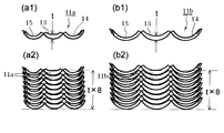
図5はバインダーの1/3リング部14, 15を折り曲げて相互に嵌合させる直前の状態を示し、(b)は図1乃至図4のバインダー11bであり、(a)はバインダー11bより小径のバインダー11aを示している。バインダー11aとバインダー11bはリングピッチやリング部13, 14, 15の幅などは同一であり、外径及び内径が相違していて、綴じる用紙の枚数に応じて適切な径のバインダーを選択してバインド処理機に装填して使用できるようにシステム化を図っている。
FIG. 5 shows a state immediately before the 1/3
図6に1/3リング部14, 15を嵌合させた状態を示す(ここでは背骨部12の図示を省略している)。図6(a1)(b1)は夫々嵌合部位を上に向けた状態で、図6(a2)(b2)は夫々嵌合部位を下に向けた状態である。
FIG. 6 shows a state in which the 1/3
図7(a1)(b1)は嵌合直前の状態の断面を示し、図7(a2)(b2)は嵌合状態の断面を示している。図7(a1)(b1)に示すように、リング径の異なる二種のバインダー11aとバインダー11bは、中央1/3リング部13の中央部における径方向の厚さtが同一である。また、中央1/3リング部13には、外周面中央部を貫通穴21と等しい幅で法線直交方向に切り欠いた形状の平面部22が形成されていて、二種のバインダー11aとバインダー11bの夫々の平面部22とこれに平行な外周面の接線との距離dも同一である。
FIGS. 7 (a1) and (b1) show cross sections immediately before the fitting, and FIGS. 7 (a2) and (b2) show cross sections in the fitting state. As shown in FIGS. 7 (a1) and (b1), the two types of
図8(a1)(b1)に示すように、二種類のバインダー11a, 11bの中央1/3リング部13の厚さtは同一であり、複数のバインダーを隙間なく密着させて積層することができるから、図8(a2)(b2)に示すように、夫々同じ数量(ここでは8本)のバインダー11a, 11bを積層した場合の厚さも同一となる。したがって、バインド処理機において、カートリッジ内のバインダーの送り量制御や、送りのためにバインダーを押すプッシャーの移動量からバインダーの残量を検出する制御などを画一化でき、制御部の処理が簡単になる。
As shown in FIGS. 8 (a1) and (b1), the thickness t of the central 1/3
図9は図1及び図2中のA部の拡大図であり、図1に示す三箇所のA部で指示した中央1/3リング部13の両側面には位置規制部として球面形状の凸部23が形成されている。図示は省略するが、バインド処理機のカートリッジに積層して装填したバインダーは、カートリッジ内の送りガイドGによって横方向の移動を規制されて、図9において紙面の奥方向へ送られるが、バインダーに線膨張が生じた場合であっても、前述したように中央1/3リング部13のリング間距離の伸縮を貫通穴21で吸収して、リング部の位置を正規の位置に保つことができる。また、バインダーの側面が送りガイドGの壁面に接触しても、一つまたは複数のリング部の片側面または両側面に設けた凸部23によって、中央1/3リング部13の側面は送りガイドの壁面へ点接触の状態となり、リング部全体が送りガイドに面接触することがなく、低摩擦抵抗で円滑に送られる。
FIG. 9 is an enlarged view of portion A in FIGS. 1 and 2, and spherical projections as position restricting portions are formed on both side surfaces of the central 1/3
図10は、リング部の先端の嵌合機構を示し、(a)(c)に示すように、上方へ隆起するフック部17を設けた1/3リング部14の内周面左右両側にステップ形の段差部24を形成し、キャッチ部18を設けた1/3リング部15の外周面の左右両側には、他方の1/3リング部14の段差部24と対応する段差部25を形成して、双方の段差部24, 25を重ねると一体化する相欠け継ぎ構造としている。
Fig. 10 shows the fitting mechanism at the tip of the ring part. As shown in (a) and (c), steps are provided on the left and right sides of the inner peripheral surface of the 1/3
1/3リング部14のフック部17は、その左右の段差部24よりも奥へ後退した位置にあり、段差部24との間にはスリットが設けられていて、フック部17は自由に撓むことができる。
The
他方の1/3リング部15のキャッチ部18は、その後端の垂直壁にフック部17を係合させるもので、垂直壁の位置は左右の段差部25よりも奥へ後退した位置にあるが、キャッチ部18の先端は段差部25より前方へ突出している。
The
対向する一対の1/3リング部14, 15を嵌合させるべく接近させると、先ず一方の1/3リング部15のキャッチ部18の先端が他方の1/3リング部14の左右の段差部24の間に入って、横方向の位置決めが行われるとともに、双方の段差部24, 25が摺接して縦方向(半径方向)の位置が合い、さらに一対の1/3リング部14, 15を閉じていくとフック部17の上向きの爪がキャッチ部18の後端の垂直壁に係合して両者が結合される。
When the pair of opposing 1/3
このように、一対の1/3リング部14, 15を閉じるときに、先ず双方の先端部が位置合わせされてからフック部17とキャッチ部18が係合するので、位置がずれて嵌合不良が生じることがない。
Thus, when closing the pair of 1/3
1/3リング部15のキャッチ部18の背後には半径方向へ貫通する穴26が設けられており、図7(a2)(b2)に示すように、嵌合状態においてフック部17の先端が穴26内に露出して見えるので、穴26の上からピンなどでフック部17を押し下げてフック部17とキャッチ部18との係合を解除することにより、一対の1/3リング部14, 15を開放することができる。
A
また、図7及び図10から判断できるように、一対の1/3リング部14, 15の嵌合機構をアンダーカット部分が無い断面形状としているので、複雑なスライドコア金型を用いずに成形できるものである。
Also, as can be judged from FIGS. 7 and 10, the fitting mechanism of the pair of 1/3
尚、嵌合した一対の1/3リング部14, 15を指などで押し広げれば、その応力によりフック部17が弾性変形して一対の1/3リング部14, 15を開放することができるので、上記の穴26は必須のものではなく、図11(a)のバインダー31に示すように穴を設けなくともよいが、穴を設けることによってフック部17に伸長応力をかけずにリング部を開放することができ、フック部17を破損する虞が少ないという利点がある。
If the pair of 1/3
図11(b)は他の実施形態を示し、バインダー41の一対の1/3リング部42, 43は対称形であって、夫々先端の半分を上向きフック部44とし、他の半分を下向きフック部45としてあり、一対の1/3リング部42, 43を閉じると、対向する上向きフック部44と下向きフック部45とが係合して一対の1/3リング部42, 43が結合される。
FIG. 11 (b) shows another embodiment, in which the pair of 1/3
尚、必ずしも全ての1/3リング部42, 43の先端に上向きフック部44と下向きフック部45を設ける必要はなく、バインダー41の長手方向両端のリング部とその間の要所のリング部の先端にのみ、両フック部44, 45を設けるようにしてもよい。
Note that it is not always necessary to provide the
図12及び図13は、バインド処理機のバインダピックアップユニット51がバインダー11bを掴んだ状態を示している。バインド処理機については種々の構成が考えられるが、バインダピックアップユニット51は、多数のバインダーが積層状態で装填されたカートリッジから一つのバインダーを取出して、用紙へ装着する綴じ処理機構部へバインダーを供給する手段の一例である。
12 and 13 show a state in which the
バインダピックアップユニット51は、図14に示すテーブルブロック52とその前後両面に配置されるフックレバーブロック53とをフレーム(図示せず)に組み付けたものである。テーブルブロック52の上面にはバインダー11bのリングピッチと同一ピッチで平面テーブル54が設けられていて、この平面テーブル54の上面で図7に示したバインダー11a, 11bの中央1/3リング部13の平面部22を受ける。前後で対をなすフックレバーブロック53は、複数のフックレバー55をリングピッチと同一ピッチで櫛歯形に配列したもので、対向するフックレバー55は複数の平面テーブル54の間に千鳥配置され、レバー開閉機構(図示せず)により対称的に開閉し、閉じることによってバインダー11a, 11bのT型断面背骨部12の段差部分を掴む。
The binder pick-up
図15にその詳細を示す。(1)はバインダー11bを把持したバインダピックアップユニットを示し、(a0)(b0)は二種のバインダー11aとバインダー11bを示し、(a1)(a2)(b1)(b2)は夫々バインダピックアップユニット51がバインダー11aとバインダー11bを掴んだ状態の断面を示している。
The details are shown in FIG. (1) indicates a binder pickup unit that holds the
既に述べたように、二種のバインダー11aとバインダー11bの夫々の平面部22とこれに平行な外周面の接線との距離dは同一であるので、平面部22と背骨部12との位置関係も同一であり、(a2)(b2)に示すように前後一対のフックレバー55は、バインダーのサイズにかかわらず夫々T型断面の背骨部12の段差部分に掛かって背骨部12をテーブルブロック52に押さえつけ、平面部22もテーブルブロック52の平面テーブル54へ押し当てられる。
As already described, since the distance d between the
バインダー11a, 11bに平面部22を設け、平面部22をテーブルブロック52の平面テーブル54で受けるようにしたことにより、バインダー11a, 11bの姿勢が傾くことがなく、正規の姿勢で安定して把持される。また、バインダー11a, 11bの平面部22の左右は中央1/3リング部13の側面壁にかこまれているので、テーブルブロック52の平面テーブル54が平面部22に嵌合することにより、バインダー11a, 11bの長手方向の位置決めが行われる。また、前述したように中央1/3リング部13に貫通穴21を形成して幅方向の撓みを許容するようにしているので、熱変化によりバインダー11a, 11bの全長が延びた場合であっても、中央1/3リング部13の平面部22がテーブルブロック52の平面テーブル54に嵌合することにより、リングピッチの偏差が強制的に矯正され、正規のリングピッチでバインド処理を行うことができる。
By providing the
尚、この発明は上記の実施形態に限定するものではなく、この発明の技術的範囲内において種々の改変が可能であり、この発明がそれらの改変されたものに及ぶことは当然である。 Note that the present invention is not limited to the above-described embodiment, and various modifications are possible within the technical scope of the present invention, and the present invention naturally extends to those modified ones.
11a. 11b バインダー
12 背骨部
13 中央1/3リング部
14. 15 1/3リング部
17 フック部
18 キャッチ部
19 ピン
20 ピン穴
21 貫通穴
22 平面部
23 凸部
24. 25 段差部
51 バインダピックアップユニット
52 テーブルブロック
53 フックレバーブロック
54 平面テーブル
55 フックレバー
11a. 11b Binder
12 spine
13
14.15 1/3 ring part
17 Hook
18 Catch section
19 pin
20 pin hole
21 Through hole
22 Plane section
23 Convex
24. 25 Step
51 Binder pickup unit
52 Table block
53 Hook lever block
54 Flat table
55 Hook lever
Claims (4)
夫々の前記リング部の側面間に背骨部を介装して連結し、一つまたは複数のリング部の背骨部のバインダーの長手方向の中心線と直交する部位に貫通穴を設け、バインダーの長手方向の線膨張を吸収できるようにしたことを特徴とするバインダー。 A plastic binder that binds perforations formed at the edge of the paper, wherein a plurality of ring portions that can be opened and closed are arranged at regular intervals on both sides in the longitudinal direction of the spine portion,
A spine portion is interposed between the side surfaces of each of the ring portions, and a through hole is provided in a portion perpendicular to the longitudinal center line of the binder of the spine portion of one or a plurality of ring portions. A binder characterized by being able to absorb linear expansion in a direction.
バインダーの側面が、バインド処理機のバインダガイドの壁面と接触しても、一つまたは複数のリング部の片側面または両側面が当該バインダガイドの壁面へ点接触の状態となるものであって、かつリング部の全体が、バインド処理機のバインダガイドに面接触することがなく低摩擦抵抗で円滑にバインダーを送る機能を備えた、バインド処理機のバインダガイドの壁面と当接して上記リング部の位置を規制する位置規制部を、
一つまたは複数のリング部の片側面又は両側面に設けたことを特徴とするバインダー。 A plastic binder that binds perforations formed at the edge of the paper, wherein a plurality of ring portions that can be opened and closed are arranged at regular intervals on both sides in the longitudinal direction of the spine portion,
Even if the side surface of the binder comes into contact with the wall surface of the binder guide of the bind processing machine , one side surface or both side surfaces of one or a plurality of ring portions are in point contact with the wall surface of the binder guide, In addition, the entire ring part is in contact with the wall surface of the binder guide of the bind processing machine and has a function of smoothly feeding the binder with low friction resistance without surface contact with the binder guide of the bind processing machine. the position regulating portion for regulating the position,
A binder characterized by being provided on one or both side surfaces of one or a plurality of ring portions.
バインダーの側面が、バインド処理機のバインダガイドの壁面と接触しても、一つまたは複数のリング部の片側面または両側面が当該バインダガイドの壁面へ線接触の状態となるものであって、かつリング部の全体が、バインド処理機のバインダガイドに面接触することがなく低摩擦抵抗で円滑にバインダーを送る機能を備えた、バインド処理機のバインダガイドの壁面と当接して上記リング部の位置を規制する位置規制部を、
一つまたは複数のリング部の片側面又は両側面に設けたことを特徴とするバインダー。 A plastic binder for binding the perforations formed in the edge of the paper, in a binder having an array of ring portions at regular intervals that can be multiple opening and closing in the longitudinal direction side surfaces of the spine,
Even if the side surface of the binder comes into contact with the wall surface of the binder guide of the bind processing machine, one side surface or both side surfaces of the one or more ring portions are in line contact with the wall surface of the binder guide, In addition, the entire ring part is in contact with the wall surface of the binder guide of the bind processing machine and has a function of smoothly feeding the binder with low friction resistance without surface contact with the binder guide of the bind processing machine. The position restricting part that restricts the position
A binder characterized by being provided on one or both side surfaces of one or a plurality of ring portions.
Priority Applications (8)
| Application Number | Priority Date | Filing Date | Title |
|---|---|---|---|
| JP2005216314A JP4635766B2 (en) | 2005-07-26 | 2005-07-26 | binder |
| TW095127098A TW200716394A (en) | 2005-07-26 | 2006-07-25 | Binder |
| PCT/JP2006/314771 WO2007013509A1 (en) | 2005-07-26 | 2006-07-26 | Binder |
| EP06781683A EP1908601B1 (en) | 2005-07-26 | 2006-07-26 | Binder with ring parts |
| US11/996,911 US8568052B2 (en) | 2005-07-26 | 2006-07-26 | Binder |
| DE602006019257T DE602006019257D1 (en) | 2005-07-26 | 2006-07-26 | BINDING DEVICE WITH RINGS |
| CNB2006800277287A CN100509436C (en) | 2005-07-26 | 2006-07-26 | Binder |
| CN2009100078823A CN101513806B (en) | 2005-07-26 | 2006-07-26 | Binder |
Applications Claiming Priority (1)
| Application Number | Priority Date | Filing Date | Title |
|---|---|---|---|
| JP2005216314A JP4635766B2 (en) | 2005-07-26 | 2005-07-26 | binder |
Publications (2)
| Publication Number | Publication Date |
|---|---|
| JP2007030319A JP2007030319A (en) | 2007-02-08 |
| JP4635766B2 true JP4635766B2 (en) | 2011-02-23 |
Family
ID=37683400
Family Applications (1)
| Application Number | Title | Priority Date | Filing Date |
|---|---|---|---|
| JP2005216314A Active JP4635766B2 (en) | 2005-07-26 | 2005-07-26 | binder |
Country Status (7)
| Country | Link |
|---|---|
| US (1) | US8568052B2 (en) |
| EP (1) | EP1908601B1 (en) |
| JP (1) | JP4635766B2 (en) |
| CN (2) | CN100509436C (en) |
| DE (1) | DE602006019257D1 (en) |
| TW (1) | TW200716394A (en) |
| WO (1) | WO2007013509A1 (en) |
Families Citing this family (15)
| Publication number | Priority date | Publication date | Assignee | Title |
|---|---|---|---|---|
| JP4715391B2 (en) * | 2005-08-26 | 2011-07-06 | マックス株式会社 | Binder cartridge |
| JP5660355B2 (en) | 2008-03-17 | 2015-01-28 | 株式会社リコー | Bookbinding system |
| JP2009248509A (en) | 2008-04-09 | 2009-10-29 | Ricoh Co Ltd | Bookbinding system, bookbinding method and computer program |
| JP5217978B2 (en) * | 2008-12-02 | 2013-06-19 | 株式会社リコー | Bookbinding system, binding function selection display method, computer program, and recording medium |
| JP5338381B2 (en) | 2009-03-03 | 2013-11-13 | 株式会社リコー | Bookbinding system, bookbinding control method, and bookbinding control program |
| JP5440417B2 (en) * | 2010-06-25 | 2014-03-12 | コニカミノルタ株式会社 | Ring binding apparatus and image forming system provided with the ring binding apparatus |
| JP5614149B2 (en) * | 2010-07-29 | 2014-10-29 | コニカミノルタ株式会社 | Image forming system |
| JP5510241B2 (en) | 2010-09-25 | 2014-06-04 | コニカミノルタ株式会社 | Image forming system having ring binding function |
| JP6106887B2 (en) * | 2012-04-13 | 2017-04-05 | グラドコジャパン株式会社 | Bookbinding equipment |
| JP6149285B2 (en) * | 2012-04-13 | 2017-06-21 | グラドコジャパン株式会社 | Bookbinding equipment |
| US20160059613A1 (en) * | 2014-09-03 | 2016-03-03 | Shantu Patel | Items for Stationary from Eco Friendly Materials and Resins |
| CN104476942A (en) * | 2014-12-08 | 2015-04-01 | 江苏申凯包装高新技术股份有限公司 | Record book with replaceable paper |
| JP6469186B1 (en) * | 2017-08-01 | 2019-02-13 | 株式会社リヒトラブ | Binding tool |
| JP6516275B1 (en) * | 2018-07-04 | 2019-05-22 | 株式会社カネダ技研 | Binding tool |
| CN113352055B (en) * | 2021-06-03 | 2022-07-19 | 义乌市喜鹊印业有限公司 | Processing technology of scratch-proof antioxidant loose-leaf binder |
Citations (5)
| Publication number | Priority date | Publication date | Assignee | Title |
|---|---|---|---|---|
| US5618122A (en) * | 1993-02-04 | 1997-04-08 | C-Lock, Inc. | Molded plastic one-piece loose-leaf binder ring structure |
| JP2002502728A (en) * | 1998-02-05 | 2002-01-29 | ブレインウェイブ リミテッド | Ring binder mechanism |
| JP2002205481A (en) * | 2001-01-09 | 2002-07-23 | Lihit Lab Inc | Binder set and binder |
| JP2004237578A (en) * | 2003-02-06 | 2004-08-26 | Max Co Ltd | Binder |
| JP2005059396A (en) * | 2003-08-12 | 2005-03-10 | Max Co Ltd | Binding method, binding device and binder cartridge |
Family Cites Families (11)
| Publication number | Priority date | Publication date | Assignee | Title |
|---|---|---|---|---|
| US2399561A (en) * | 1943-11-13 | 1946-04-30 | Wilson Jones Co | Loose-leaf binder |
| GB961663A (en) * | 1960-06-03 | 1964-06-24 | Cakebread Ltd C | Improvements relating to loose-leaf binders |
| US4932804A (en) * | 1988-11-18 | 1990-06-12 | Richards Donna E | Loose leaf retainer for file folders |
| ES1015339Y (en) * | 1990-10-10 | 1991-12-16 | Carrascosa Hernandez Luis | IMPROVEMENTS IN FOLDERS THAT INCORPORATE IN THE INTERNAL LOIN THE CANUTILLO BINDING SYSTEM. |
| DE4434769A1 (en) * | 1994-09-29 | 1996-04-04 | Friedrich Von Rohrscheidt | Ring comb binder mfd. by injection moulding, to hold stacked sheets of paper |
| US6062760A (en) * | 1998-01-19 | 2000-05-16 | U.S. Ring Binder Corp. | Modular binder ring construction |
| JP2000289376A (en) | 1999-03-31 | 2000-10-17 | Ibico Trading Gmbh | Binder for fixing back part |
| WO2003093025A1 (en) * | 2002-04-30 | 2003-11-13 | Max Co., Ltd. | Binder and binding device |
| JP4296793B2 (en) | 2003-02-06 | 2009-07-15 | マックス株式会社 | binder |
| JP4300814B2 (en) | 2003-02-06 | 2009-07-22 | マックス株式会社 | binder |
| US7077595B2 (en) | 2003-07-25 | 2006-07-18 | General Binding Corporation | Spine binder |
-
2005
- 2005-07-26 JP JP2005216314A patent/JP4635766B2/en active Active
-
2006
- 2006-07-25 TW TW095127098A patent/TW200716394A/en not_active IP Right Cessation
- 2006-07-26 EP EP06781683A patent/EP1908601B1/en active Active
- 2006-07-26 DE DE602006019257T patent/DE602006019257D1/en active Active
- 2006-07-26 WO PCT/JP2006/314771 patent/WO2007013509A1/en active Application Filing
- 2006-07-26 CN CNB2006800277287A patent/CN100509436C/en not_active Expired - Fee Related
- 2006-07-26 CN CN2009100078823A patent/CN101513806B/en not_active Expired - Fee Related
- 2006-07-26 US US11/996,911 patent/US8568052B2/en active Active
Patent Citations (5)
| Publication number | Priority date | Publication date | Assignee | Title |
|---|---|---|---|---|
| US5618122A (en) * | 1993-02-04 | 1997-04-08 | C-Lock, Inc. | Molded plastic one-piece loose-leaf binder ring structure |
| JP2002502728A (en) * | 1998-02-05 | 2002-01-29 | ブレインウェイブ リミテッド | Ring binder mechanism |
| JP2002205481A (en) * | 2001-01-09 | 2002-07-23 | Lihit Lab Inc | Binder set and binder |
| JP2004237578A (en) * | 2003-02-06 | 2004-08-26 | Max Co Ltd | Binder |
| JP2005059396A (en) * | 2003-08-12 | 2005-03-10 | Max Co Ltd | Binding method, binding device and binder cartridge |
Also Published As
| Publication number | Publication date |
|---|---|
| DE602006019257D1 (en) | 2011-02-10 |
| EP1908601B1 (en) | 2010-12-29 |
| WO2007013509A1 (en) | 2007-02-01 |
| CN100509436C (en) | 2009-07-08 |
| CN101513806B (en) | 2010-12-01 |
| CN101513806A (en) | 2009-08-26 |
| JP2007030319A (en) | 2007-02-08 |
| TW200716394A (en) | 2007-05-01 |
| TWI363003B (en) | 2012-05-01 |
| EP1908601A1 (en) | 2008-04-09 |
| US20100135713A1 (en) | 2010-06-03 |
| US8568052B2 (en) | 2013-10-29 |
| CN101232999A (en) | 2008-07-30 |
| EP1908601A4 (en) | 2008-09-17 |
Similar Documents
| Publication | Publication Date | Title |
|---|---|---|
| JP4635766B2 (en) | binder | |
| JP4635767B2 (en) | binder | |
| JP4635768B2 (en) | binder | |
| US9688091B2 (en) | Ring binder mechanism | |
| JP2017105099A (en) | Clip file | |
| JP2010069863A (en) | Binder | |
| US8545122B2 (en) | Binding device | |
| JP3211991U (en) | Paper binding tool | |
| JP5810256B2 (en) | Binding tools and files | |
| JP4809895B2 (en) | Binding tool for file binder | |
| JP2007320159A (en) | Binder and filing implement equipped therewith | |
| JP7328684B2 (en) | binding tool | |
| JP4251112B2 (en) | Binding tools and files | |
| US20100322701A1 (en) | Novel modification of plastic lay-flat binding comb | |
| JP6311326B2 (en) | Binding tools and files | |
| JP3144863U (en) | Binding assist device | |
| EP3332984B1 (en) | Media binder arrangement and a method of manufacturing a media binder | |
| JP6016837B2 (en) | Notebook | |
| MX2008001343A (en) | Binder | |
| KR100988731B1 (en) | Support member for fixing of diary | |
| JP4160867B2 (en) | Sheet pressing member, binding tool, file | |
| JP2006021326A (en) | Sheet binding file and sheet binder | |
| JP2004216688A (en) | File | |
| JPH11309973A (en) | Stopper for file | |
| JP2011251428A (en) | Binder and file |
Legal Events
| Date | Code | Title | Description |
|---|---|---|---|
| A621 | Written request for application examination |
Free format text: JAPANESE INTERMEDIATE CODE: A621 Effective date: 20080327 |
|
| A131 | Notification of reasons for refusal |
Free format text: JAPANESE INTERMEDIATE CODE: A131 Effective date: 20100907 |
|
| A521 | Request for written amendment filed |
Free format text: JAPANESE INTERMEDIATE CODE: A523 Effective date: 20101014 |
|
| TRDD | Decision of grant or rejection written | ||
| A01 | Written decision to grant a patent or to grant a registration (utility model) |
Free format text: JAPANESE INTERMEDIATE CODE: A01 Effective date: 20101026 |
|
| A01 | Written decision to grant a patent or to grant a registration (utility model) |
Free format text: JAPANESE INTERMEDIATE CODE: A01 |
|
| A61 | First payment of annual fees (during grant procedure) |
Free format text: JAPANESE INTERMEDIATE CODE: A61 Effective date: 20101108 |
|
| FPAY | Renewal fee payment (event date is renewal date of database) |
Free format text: PAYMENT UNTIL: 20131203 Year of fee payment: 3 |
|
| R150 | Certificate of patent or registration of utility model |
Ref document number: 4635766 Country of ref document: JP Free format text: JAPANESE INTERMEDIATE CODE: R150 Free format text: JAPANESE INTERMEDIATE CODE: R150 |