JP4635537B2 - Liquid developing device and image forming apparatus - Google Patents
Liquid developing device and image forming apparatus Download PDFInfo
- Publication number
- JP4635537B2 JP4635537B2 JP2004274501A JP2004274501A JP4635537B2 JP 4635537 B2 JP4635537 B2 JP 4635537B2 JP 2004274501 A JP2004274501 A JP 2004274501A JP 2004274501 A JP2004274501 A JP 2004274501A JP 4635537 B2 JP4635537 B2 JP 4635537B2
- Authority
- JP
- Japan
- Prior art keywords
- roller
- developer
- developing
- developer carrier
- developing roller
- Prior art date
- Legal status (The legal status is an assumption and is not a legal conclusion. Google has not performed a legal analysis and makes no representation as to the accuracy of the status listed.)
- Expired - Fee Related
Links
Images


Description
この発明は、プリンタ、複写機やファクシミリ装置などの電子写真方式の画像形成技術、特に現像方式として湿式現像方式を採用した画像形成技術に関するものである。 The present invention relates to an electrophotographic image forming technique such as a printer, a copying machine or a facsimile machine, and more particularly to an image forming technique adopting a wet developing method as a developing method.
従来より、湿式現像方式を採用した画像形成装置としては、現像ローラ(現像剤担持体)の表面に均一な厚さに塗布された液体現像剤で、潜像担持体に形成された静電潜像を現像することによって、濃度ムラのない画像を形成する構成が知られている。このように、現像ローラの表面に液体現像剤を均一に塗布する技術としては、次のような技術が従来より提案されている。すなわち、現像ローラの表面に液体現像剤を塗布する前に、一旦、アニロクスローラ(塗布ローラ)の表面に、該アニロクスローラの回転方向に対して規則正しく斜めに形成された彫刻(溝)部に液体現像剤を担持することによって、液体現像剤の液量を正確に計量する。そして、該アニロクスローラで正確に計量した液体現像剤を現像ローラに塗布することによって、正確に計量された液体現像剤を現像ローラに転移させて、該現像ローラに均一な厚さの現像液薄層を形成することができる(例えば特許文献1参照)。 2. Description of the Related Art Conventionally, an image forming apparatus adopting a wet development system has a liquid developer applied to the surface of a developing roller (developer carrying member) with a uniform thickness, and an electrostatic latent image formed on a latent image carrying member. There has been known a configuration in which an image without density unevenness is formed by developing the image. As described above, the following techniques have been conventionally proposed as techniques for uniformly applying the liquid developer to the surface of the developing roller. That is, before applying the liquid developer to the surface of the developing roller, the engraving (groove) portion once formed on the surface of the anilox roller (application roller) regularly and obliquely with respect to the rotation direction of the anilox roller. By carrying the liquid developer on the liquid developer, the amount of the liquid developer is accurately measured. Then, the liquid developer accurately measured by the anilox roller is applied to the developing roller, so that the accurately measured liquid developer is transferred to the developing roller, and the developer having a uniform thickness is transferred to the developing roller. A thin layer can be formed (see, for example, Patent Document 1).
ところで、上記した従来装置では、塗布ローラの表面と現像剤担持体の表面とを当接させながら回転させることによって、塗布ローラに形成された溝に担持された液体現像剤を、現像剤担持体に塗布している。そのため、塗布ローラおよび現像剤担持体に次のようなスラスト力が発生することがあった。すなわち、上記した特許文献1に記載の装置では、塗布ローラの表面に、その回転方向に対して規則正しく斜めに溝が形成されており、該塗布ローラと現像剤担持体とは当接しながら回転している。その結果、塗布ローラおよび現像剤担持体にスラスト力が発生し、次のような問題が生じることがあった。
By the way, in the above-described conventional apparatus, the liquid developer carried in the groove formed on the coating roller is rotated by rotating the surface of the coating roller while contacting the surface of the developer carrier. It is applied to. Therefore, the following thrust force may be generated on the application roller and the developer carrying member. That is, in the apparatus described in
この種の画像形成装置において、現像剤担持体は製造誤差や組立性などを考慮してスラスト方向に遊びが生じるように設計されており、該スラスト方向に移動自在となっていることがある。そのため、上記のようにして現像剤担持体にスラスト力が発生すると、現像剤担持体が移動してしまい、スラスト方向における潜像担持体および塗布ローラに対する現像剤担持体の位置が安定しないことがあった。その結果、現像動作時において、スラスト方向における潜像担持体に対する現像剤担持体の当接位置が不安定となることにより、潜像担持体上の静電潜像を現像する現像精度が劣化してしまうことがあった。また、スラスト方向における塗布ローラに対する現像剤担持体の当接位置が不安定となることにより、現像剤担持体に塗布する液体現像剤の塗布パターンが乱れてしまうことがあった。このような塗布パターンの乱れは現像精度の劣化を招いてしまう。 In this type of image forming apparatus, the developer carrier is designed so that play is generated in the thrust direction in consideration of manufacturing errors, assemblability, and the like, and may be movable in the thrust direction. Therefore, when a thrust force is generated in the developer carrier as described above, the developer carrier moves, and the position of the developer carrier relative to the latent image carrier and the application roller in the thrust direction may not be stable. there were. As a result, the developing accuracy for developing the electrostatic latent image on the latent image carrier deteriorates due to the unstable contact position of the developer carrier with respect to the latent image carrier in the thrust direction during the developing operation. There was a case. Further, the contact position of the developer carrier with respect to the application roller in the thrust direction becomes unstable, so that the application pattern of the liquid developer applied to the developer carrier may be disturbed. Such disturbance of the coating pattern causes deterioration in development accuracy.
また、上記においては、スラスト方向における現像剤担持体の移動による課題について説明したが、塗布ローラについても同様の問題が生じることがあった。すなわち、塗布ローラについても製造誤差等を考慮してスラスト方向に移動自在となっていることがある。したがって、上記のようにして発生したスラスト力が塗布ローラに印加されて現像剤担持体に対する塗布ローラの位置が安定しないことがあった。その結果、現像剤担持体に塗布される塗布パターンに乱れが生じて、現像精度が劣化してしまう。 In the above description, the problem due to the movement of the developer carrying member in the thrust direction has been described. However, a similar problem may occur in the application roller. That is, the application roller may be movable in the thrust direction in consideration of manufacturing errors and the like. Therefore, the thrust force generated as described above is applied to the application roller, and the position of the application roller with respect to the developer carrier may not be stable. As a result, the coating pattern applied to the developer carrying member is disturbed and the development accuracy is deteriorated.
この発明は上記課題に鑑みなされたものであり、斜め溝を有する塗布ローラにより現像剤担持体に液体現像剤を塗布する構成において、現像動作時における潜像担持体および塗布ローラに対する現像剤担持体の移動を防止して現像精度の向上を図ることを目的とする。 The present invention has been made in view of the above problems, and in the configuration in which the liquid developer is applied to the developer carrier by the application roller having the oblique grooves, the latent image carrier and the developer carrier to the application roller during the developing operation. It is an object of the present invention to improve the development accuracy by preventing the movement of the toner.
この発明は、上記目的を達成するため、現像剤担持体と、回転方向に対して斜めに設けられた溝を有しており、溝に液体現像剤を担持しながら現像剤担持体と接触する位置に搬送して該液体現像剤を現像剤担持体に塗布する塗布ローラと、現像剤担持体を塗布ローラの回転方向に直交もしくはほぼ直交するスラスト方向における現像剤担持体係止位置で係止する現像剤担持体用位置決め部と、塗布ローラと現像剤担持体とが当接しながら回転することによって発生するスラスト力により現像剤担持体が移動する方向に、現像剤担持体を付勢する現像剤担持体用付勢部材と、を備えたことを特徴とする。 In order to achieve the above object, the present invention has a developer carrier and a groove provided obliquely with respect to the rotation direction, and contacts the developer carrier while carrying the liquid developer in the groove. An application roller that transports the liquid developer onto the developer carrier and the developer carrier is locked at a developer carrier locking position in a thrust direction that is orthogonal or substantially orthogonal to the rotation direction of the application roller. Development for urging the developer carrier in the direction in which the developer carrier moves due to the thrust force generated by rotating the positioning portion for the developer carrier to be rotated while the coating roller and the developer carrier are in contact with each other And an urging member for the agent carrier.
このように構成された発明では、現像剤担持体を第1方向にほぼ直交するスラスト方向における所定の現像剤担持体係止位置で係止する現像剤担持体用位置決め部を設けるとともに、塗布ローラと前記現像剤担持体とが当接しながら回転することによって発生するスラスト力により現像剤担持体が移動しようとする方向と同じ方向に、現像剤担持体用付勢部材によって現像剤担持体を付勢している。そのため、例えば、現像剤担持体が製造誤差や組立性などを考慮してスラスト方向に遊びが生じるように設計されており、該スラスト方向に移動自在となっている場合でも、現像動作時に、現像剤担持体をスラスト力と現像剤担持体用付勢部材の付勢力の2つの力によって、短時間でスラスト方向における所定の現像剤担持体係止位置に移動させて、現像剤担持体用位置決め部により係止することができる。このように、現像剤担持体を、短時間で所定の現像剤担持体係止位置での係止状態とすることができる。そして、この2つの力によって、現像剤担持体を所定の現像剤担持体係止位置で現像剤担持体用位置決め部により確実に係止することができる。したがって、現像動作時における潜像担持体および塗布ローラに対する現像剤担持体の移動を防止して現像精度の劣化を防止し、現像精度の向上を図ることができる。 In the invention thus configured, a developer carrier positioning portion for locking the developer carrier at a predetermined developer carrier locking position in a thrust direction substantially orthogonal to the first direction is provided, and a coating roller The developer carrier is attached to the developer carrier by a biasing member for the developer carrier in the same direction as the developer carrier is about to move due to the thrust force generated by the rotation of the developer carrier and the developer carrier. It is fast. Therefore, for example, the developer carrier is designed so that play is generated in the thrust direction in consideration of manufacturing errors, assembling, etc., and even when the developer carrier is movable in the thrust direction, the development is performed during the developing operation. The developer carrier is moved to a predetermined developer carrier locking position in the thrust direction in a short time by the thrust force and the urging force of the developer carrier urging member, thereby positioning the developer carrier. It can be locked by the part. In this way, the developer carrier can be brought into a locked state at a predetermined developer carrier locking position in a short time. By these two forces, the developer carrier can be reliably locked by the developer carrier positioning portion at a predetermined developer carrier locking position. Accordingly, it is possible to prevent the development carrier from being deteriorated by preventing the developer carrier from moving relative to the latent image carrier and the application roller during the developing operation, and to improve the development accuracy.
また、前記現像剤担持体用付勢部材は、前記現像剤担持体と前記潜像担持体との間に作用する静止摩擦力と、前記現像剤担持体と前記塗布ローラとの間に作用する静止摩擦力との和よりも大きな付勢力を有している構成とするのが望ましい。このような構成とすれば、現像剤担持体用付勢部材が有する付勢力のみで、現像剤担持体を現像剤担持体係止位置に移動させて、現像剤担持体用位置決め部により係止することができる。そのため、装置組立時において、現像剤担持体は現像剤担持体係止位置に位置決めされる。したがって、現像動作時に現像剤担持体にスラスト力が発生した際に、現像剤担持体は既に所定の現像剤担持体係止位置で現像剤担持体用位置決め部により既に係止されており、現像剤担持体に発生したスラスト力によって、該現像剤担持体がさらに移動することはない。また、現像現像剤担持体は、現像剤担持体用付勢部材が有する付勢力およびスラスト力の2つの力が作用することにより、スラスト方向における所定の現像剤担持体係止位置で現像剤担持体用位置決め部により強固に係止されている。したがって、現像動作時に、例えば、振動によって装置が傾いたりしたとしても、現像剤担持体が所定の現像剤担持体係止位置から移動してしまうのを確実に防止することができる。また、現像動作開始直後から、現像剤担持体を所定の現像剤担持体係止位置に確実に係止させることができるため、より効率よく、現像動作時における潜像担持体および塗布ローラに対する現像剤担持体の移動を防止して現像精度の向上を図ることができる。 The bias member for the developer carrying member acts between the developer carrying member and the latent image carrying member, and a static frictional force acting between the developer carrying member and the latent image carrying member. It is desirable to have a configuration having a biasing force larger than the sum of the static frictional force. With such a configuration, the developer carrier is moved to the developer carrier locking position only by the biasing force of the developer carrier biasing member, and is locked by the developer carrier positioning portion. can do. Therefore, the developer carrier is positioned at the developer carrier locking position when the apparatus is assembled. Therefore, when a thrust force is generated on the developer carrier during the developing operation, the developer carrier is already locked by the developer carrier positioning portion at the predetermined developer carrier locking position. The developer carrier is not further moved by the thrust force generated in the agent carrier. In addition, the developer carrying member is loaded with the developer at a predetermined developer carrying member locking position in the thrust direction by the two forces of the biasing force and the thrust force of the biasing member for the developer carrying member. It is firmly locked by the body positioning part. Therefore, during the developing operation, for example, even if the apparatus is tilted due to vibration, it is possible to reliably prevent the developer carrier from moving from the predetermined developer carrier locking position. In addition, since the developer carrier can be reliably locked at a predetermined developer carrier locking position immediately after the start of the developing operation, the development of the latent image carrier and the coating roller during the developing operation can be performed more efficiently. It is possible to improve the development accuracy by preventing the agent carrier from moving.
<第1実施形態>
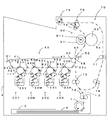
図1は本発明にかかる画像形成装置の第1実施形態であるプリンタの内部構成を示す図、図2は図1の要部拡大図、図3は同プリンタの電気的構成を示すブロック図である。この画像形成装置は、いわゆるタンデム方式のカラープリンタであり、本発明の「潜像担持体」としてイエロー(Y)、マゼンタ(M)、シアン(C)、ブラック(K)の4色の感光体11Y、11M、11C、11Kを装置本体2内に並設している。このプリンタは、湿式現像方式を採用して、各感光体11Y、11M、11C、11K上のトナー像を重ね合わせてフルカラー画像を形成したり、ブラック(K)のトナー像のみを用いてモノクロ画像を形成するものである。このプリンタでは、ホストコンピュータなどの外部装置から画像信号を含む印字指令信号が主制御部100に与えられると、この主制御部100からの制御信号に応じてエンジン制御部110がエンジン部1の各部を制御して、装置本体2の下部に配設された給紙カセット3から搬送した転写紙、複写紙およびOHP用紙などの記録媒体4に上記画像信号に対応する画像を印字出力する。
<First Embodiment>
FIG. 1 is a diagram showing an internal configuration of a printer that is a first embodiment of an image forming apparatus according to the present invention, FIG. 2 is an enlarged view of a main part of FIG. 1, and FIG. 3 is a block diagram showing an electrical configuration of the printer. is there. This image forming apparatus is a so-called tandem type color printer, and the four-color photoconductors of yellow (Y), magenta (M), cyan (C), and black (K) are used as the “latent image carrier” of the present invention. 11Y, 11M, 11C, and 11K are arranged in the apparatus
上記エンジン部1では、転写ユニット40の一構成要素である中間転写ベルト41の周回方向47に沿って並設された4つの感光体11Y、11M、11C、11Kのそれぞれに対応して、帯電部12、露光部20、現像部30(30Y、30M、30C、30K)および感光体クリーニング部14が設けられている。また、各現像部30Y、30M、30C、30Kは、各色トナーを分散した現像液32を貯留するタンク33(33Y、33M、33C、33K)をそれぞれ備えている。なお、これら帯電部12、露光部20、現像部30および感光体クリーニング部14の構成はいずれのトナー色についても同一である。したがって、ここでは、イエローに関する構成について説明し、その他のトナー色については同一または相当符号を付して説明を省略する。
In the
図2に示すように、感光体11Yは矢印の方向(図中、時計回り方向)に回転自在に設けられており、その直径は約40mmである。そして、この感光体11Yの周りには、その回転方向に沿って、帯電部12、現像ローラ31、除電部(図示省略)および感光体クリーニング部14が配設されている。また、帯電部12と現像位置16との間の表面領域が露光部20からの光ビーム21の照射領域となっている。帯電部12は、帯電バイアス発生部111から帯電バイアスが印加されて、感光体11Yの外周面を所定の表面電位Vd(例えばVd=DC+600V)に均一に帯電するもので、帯電手段としての機能を有する。
As shown in FIG. 2, the photoreceptor 11Y is rotatably provided in the direction of the arrow (clockwise direction in the figure), and its diameter is about 40 mm. A charging unit 12, a developing
この帯電部12によって均一に帯電された感光体11Yの外周面に向けて露光部20から例えばレーザで形成される光ビーム21が照射される。この露光部20は、露光制御部112から与えられる制御指令に応じて光ビーム21により感光体11Yを露光して、感光体11Y上に画像信号に対応するイエロー用静電潜像を形成するもので、露光手段としての機能を有する。例えば、ホストコンピュータなどの外部装置よりインターフェース102を介して主制御部100のCPU101に画像信号を含む印字指令信号が与えられると、主制御部100のCPU101からの指令に応じてCPU113が露光制御部112に対し所定のタイミングで画像信号に対応した制御信号を出力する。そして、この露光制御部112からの制御指令に応じて露光部20から光ビーム21が感光体11Yに照射されて、画像信号に対応するイエロー用静電潜像が感光体11Y上に形成される。また、必要に応じてパッチ画像を形成する場合には、予め設定された所定パターン(例えば、べた画像、細線画像、白抜き細線画像など)のパッチ画像信号に対応した制御信号がCPU113から露光制御部112に与えられ、該パターンに対応するイエロー用静電潜像が感光体11Y上に形成される。
A light beam 21 formed by a laser, for example, is irradiated from the
こうして形成されたイエロー用静電潜像は現像部30Yの現像ローラ31から供給されるイエロートナーによって顕像化される(現像工程)。そして、感光体11Y上に形成されたイエロートナー像は、感光体11Yの回転に伴って1次転写ローラ53Yと対向する1次転写位置42Yに搬送される。この1次転写ローラ53Yは感光体11Yとで中間転写ベルト41を挟み込むように配置されている。また、この中間転写ベルト41は複数のローラ43a〜45に掛け渡されており、図示を省略する駆動モータにより感光体11Yに従動する方向(図1中、反時計回り)47に感光体11Yと等しい周速で周回走行する。そして、転写バイアス発生部115から1次転写バイアス(例えばDC−400V)が印加されると、感光体11Y上のイエロートナー像が1次転写位置42Yで中間転写ベルト41に1次転写される(転写工程)。
The yellow electrostatic latent image formed in this way is visualized by yellow toner supplied from the developing
一方、1次転写後における感光体11Y上の残留電荷はLEDなどからなる除電部により除去され、残留現像液は感光体クリーニング部14により除去される。この感光体クリーニング部14は、感光体11Yの表面に当接されたゴム製の感光体クリーニングブレード141を有し、中間転写ベルト41にトナー像が1次転写された後に、感光体11Y上に残存する現像液32を感光体クリーニングブレード141により掻き落として除去することができる。なお、この現像部30Yの構成および動作については後で詳述する。
On the other hand, the residual charge on the photoconductor 11Y after the primary transfer is removed by a charge eliminating unit such as an LED, and the residual developer is removed by the photoconductor cleaning unit. The
また、他のトナー色についても、イエロー(Y)と同様に構成されており、画像信号に対応したトナー像が形成される。そして、感光体11Y、11M、11C、11K上に形成されたイエロー(Y)、マゼンタ(M)、シアン(C)、ブラック(K)の各色トナー像は、1次転写ローラ53Y、53M、53C、53Kと対向する1次転写位置42Y、42M、42C、42Kでそれぞれ1次転写されることにより、中間転写ベルト41の表面上で重ね合わされてフルカラーのトナー像が形成される。
The other toner colors are configured in the same manner as yellow (Y), and a toner image corresponding to the image signal is formed. The yellow (Y), magenta (M), cyan (C), and black (K) toner images formed on the photoconductors 11Y, 11M, 11C, and 11K are
中間転写ベルト41に形成されたトナー像は中間転写ベルト41の回転に伴ってローラ45、48で挟まれた2次転写位置49に搬送される。一方、給紙カセット3(図1)に収容されている記録媒体4は、1次転写トナー像の搬送に同期して後述する搬送ユニット70により2次転写位置49に搬送される。そして、ローラ48は中間転写ベルト41に従動する方向(図1中、時計回り)に中間転写ベルト41と等しい周速で回転しており、転写バイアス発生部115から2次転写バイアスが印加されると、中間転写ベルト41上のトナー像が記録媒体4に2次転写される。このローラ48としては、例えば、ゴム硬度がJIS−Aで約50度のウレタンゴムで構成されており、その直径が約25mmのものを用いることができる。なお、この実施形態ではローラ転写を採用しているため、定電圧制御により転写条件を設定したり、定電流制御により転写条件を設定することができる。また、ローラ転写の代わりに、コロナ放電により転写を行うようにしてもよいが、この場合にはコロナ放電の出力を制御することで転写条件を設定することができる。2次転写後における中間転写ベルト41上の残留現像液はクリーニングブレード51により除去される。
The toner image formed on the intermediate transfer belt 41 is conveyed to a
上記のようにしてトナー像が2次転写された記録媒体4は、所定の搬送経路5(図1中、一点鎖線)に沿って搬送され、定着ユニット60によってトナー像が記録媒体4に定着され、装置本体2の上部に設けられた排出トレイに排出される。この定着ユニット60は加熱ヒータ61hを内蔵する加熱ローラ61と、加熱ローラ61に接触する加圧ローラ62とを備えている。そして、ヒータ制御部116により加熱ヒータ61hの作動を制御することで定着ユニット60での定着温度が任意の温度に調整可能となっている。
The
また、この実施形態にかかる画像形成装置では、記録媒体4を所定の搬送経路5に沿って搬送するための搬送ユニット70が設けられている。この搬送ユニット70では、図1に示すように、給紙カセット3に対応して給紙ローラ71が設けられており、この給紙ローラ71により給紙カセット3に収容されている記録媒体4を1枚ずつ取出し、フィードローラ72に搬送する。そして、このフィードローラ72が記録媒体4をゲートローラ73に搬送し、このゲートローラ位置で一時的に待機させる。そして、上記のように2次転写動作に対応したタイミングでゲートローラ73が駆動して記録媒体4を2次転写位置49に送り込む。また、排出トレイ側では、排出前ローラ74、排出ローラ75および反転コロ76が設けられており、2次転写された記録媒体4は定着ユニット60、排出前ローラ74および排出ローラ75を経由して排出トレイ側に搬送される。
In the image forming apparatus according to this embodiment, a
ここで、両面印刷するためには記録媒体4を反転させて再度ゲートローラ73に搬送する必要があるため、排出ローラ75は正逆回転可能となっている。すなわち、記録媒体4をそのまま排出トレイに排出する際には、正回転し続けて記録媒体4を排出トレイに完全に搬送する。一方、反転再給送する際には、記録媒体4の後端部が排出前ローラ74と排出ローラ75との間の所定位置に達すると、排出ローラ75が逆回転して記録媒体4を反転コロ76に送り込む。これによって記録媒体4は反転経路5aに沿って再給送中間ローラ77に搬送される。そして、再給送中間ローラ77および再給送ゲート前ローラ78がゲートローラ73に記録媒体4を搬送し、このゲートローラ位置で一時的に待機させる。こうして、記録媒体4の反転再給送が行われる。このとき、2次転写位置49において中間転写ベルト41と当接し画像を転写される記録媒体4の面は、先に画像が転写された面とは反対の面である。このようにして、記録媒体4の両面に画像を形成することができる。また、該反対の面に2次転写が実行される際、先に画像が転写された面がローラ48に接触するが、この際、完全に記録媒体4に定着されていないトナーがローラ48に付着することがある。このようにしてローラ48に付着したトナーは、クリーニングブレード52により除去される。
Here, in order to perform double-sided printing, it is necessary to reverse the
なお、図3において、主制御部100は、インターフェース102を介して外部装置から与えられた画像信号を記憶するための画像メモリ103を備えており、CPU101は、外部装置から画像信号を含む印字指令信号をインターフェース102を介して受信すると、エンジン部1の動作指示に適した形式のジョブデータに変換し、エンジン制御部110に送出する。
In FIG. 3, the
また、エンジン制御部110のメモリ117は、予め設定された固定データを含むCPU113の制御プログラムを記憶するROMや、エンジン部1の制御データやCPU113による演算結果などを一時的に記憶するRAMなどからなる。CPU113はCPU101を介して外部装置から送られた画像信号に関するデータをメモリ117に格納する。
The memory 117 of the engine control unit 110 includes a ROM that stores a control program of the CPU 113 including preset fixed data, a RAM that temporarily stores control data of the
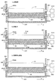
続いて、現像部30Yの構成および動作について図2、図4および図5を参照しつつ詳述する。図4は表面に溝が形成されたアニロクスローラの斜視概念図、図5は図2の矢印Aの方向から見た現像部の模式図である。なお、現像部30M,30C,30Kの構成は現像部30Yの構成と同様であり、同一構成には同一符号または相当符号を付して説明を省略する。
Next, the configuration and operation of the developing unit 30Y will be described in detail with reference to FIGS. FIG. 4 is a conceptual perspective view of an anilox roller having grooves formed on the surface, and FIG. 5 is a schematic view of the developing unit viewed from the direction of arrow A in FIG. The configurations of the developing
この現像部30Yは、現像ローラ31(本発明の「現像剤担持体」に相当)に加えて、イエロートナーを分散した現像液32を貯留するタンク33Yと、該タンク33Yに貯留された現像液32を撹拌する撹拌ローラ37と、該現像液32を汲み出して現像ローラ31に塗布する塗布ローラ34と、該塗布ローラ34上の現像液層の厚さを均一に規制する規制ブレード35と、感光体11Yへのトナー供給後に現像ローラ31上に残留した現像液を除去する現像ローラクリーニング部36とを備えている。現像ローラ31は感光体11Yに従動する方向D1(図2中、反時計回り)に感光体11Yとほぼ等しい周速で回転する。また、塗布ローラ34は現像ローラ31に従動する方向D2(図2中、時計回り、本発明の「第1方向」に相当)に現像ローラ31とほぼ等しい周速で回転する。
The developing unit 30Y includes, in addition to the developing roller 31 (corresponding to the “developer carrier” of the present invention), a
現像液32(本発明の「液体現像剤」に相当)は、本実施形態では、平均粒径0.1〜5μm程度の着色顔料、この着色顔料を接着するエポキシ樹脂などの接着剤、トナーに所定の電荷を与える荷電制御剤、着色顔料を均一に分散させる分散剤等からなるトナーが、液体キャリア中に分散されてなる。本実施形態では、液体キャリアとして、例えばポリジメチルシロキサンオイルなどのシリコーンオイルを用いており、トナー濃度を5〜40重量%として、湿式現像方式で多く用いられる低濃度現像液(トナー濃度が1〜2重量%)に比べて高濃度にしている。なお、液体キャリアの種類はシリコーンオイルに限定されるものではなく、また、現像液32の粘度は、使用する液体キャリアやトナーを構成する各材料、トナー濃度などによって決まるが、本実施形態では、例えば粘度を100〜10000mPa・sとしている。
In this embodiment, the developer 32 (corresponding to the “liquid developer” of the present invention) is applied to a color pigment having an average particle size of about 0.1 to 5 μm, an adhesive such as an epoxy resin to which the color pigment is adhered, and a toner. A toner composed of a charge control agent that gives a predetermined charge, a dispersant that uniformly disperses the color pigment, and the like is dispersed in a liquid carrier. In this embodiment, for example, a silicone oil such as polydimethylsiloxane oil is used as the liquid carrier, and the toner concentration is 5 to 40% by weight. 2% by weight). The type of the liquid carrier is not limited to silicone oil, and the viscosity of the
感光体11Yと現像ローラ31との間隔(現像ギャップ=現像液層の厚さ)は、本実施形態では例えば5〜40μmに設定し、現像ニップ距離(現像液層が感光体11Yおよび現像ローラ31の双方に接触している周方向の距離)は、本実施形態では例えば5mmに設定している。上述した低濃度現像液の場合にはトナー量を稼ぐべく100〜200μmの現像ギャップを必要とするのに比べて、高濃度現像液を用いる本実施形態では現像ギャップを短縮することができる。従って、現像液中を電気泳動によって移動するトナーの移動距離が短縮するとともに、同一の現像バイアスを印加してもより高い電界が発生するので、現像効率を向上することができ、現像を高速に行えることとなる。 In this embodiment, the distance between the photoconductor 11Y and the developing roller 31 (development gap = thickness of the developer layer) is set to, for example, 5 to 40 μm, and the development nip distance (the developer layer is the photoconductor 11Y and the developing roller 31). In this embodiment, the distance in the circumferential direction in contact with both is set to 5 mm, for example. In the case of the low-concentration developer described above, a development gap of 100 to 200 μm is required to increase the amount of toner, and in this embodiment using a high-concentration developer, the development gap can be shortened. Accordingly, the moving distance of the toner moving in the developer by electrophoresis is shortened, and a higher electric field is generated even when the same developing bias is applied, so that the developing efficiency can be improved and the developing can be performed at a high speed. It will be possible.
撹拌ローラ37は、タンク33Yに収容されている現像液32を汲み上げて塗布ローラ34へ搬送する。この撹拌ローラ37は、その下部がタンク33Yに貯留された現像液32に浸されており、また、塗布ローラ34から、約1mmの幅を持って離間している。さらに、撹拌ローラ37は、その中心軸を中心として回転可能であり、該中心軸は、塗布ローラ34の回転中心軸よりも下方にある。また、撹拌ローラ37は、塗布ローラ34の回転方向(図5中、時計回り)と同じ方向に回転する。なお、撹拌ローラ37は、タンク33Yに収容された現像液32を汲み上げて塗布ローラ34へ搬送する機能を有するとともに、現像液32を適正な状態に維持するためにを撹拌する機能をも有している。このような撹拌ローラとしては、例えば、鉄等金属性のローラであり、その直径が約20mmのものを用いることができる。
The agitating
塗布ローラ34は、タンク33Yから撹拌ローラ37により搬送された現像液32を塗布位置17において現像ローラ31へ供給する。この塗布ローラ34は、鉄等金属性のローラの表面に図4に示すように溝34aが均一かつ螺旋状に形成されニッケルメッキが施された、いわゆるアニロクスローラを呼称されるものであり、その直径は約25mmである。本実施形態では、図4に示すように、塗布ローラ34の回転方向D2に対して斜めに複数の溝34aが形成されている。塗布ローラ34にはローラ駆動部118(図3)と電気的に接続されたローラ駆動モータ340が設けられており、ローラ駆動部118からの制御信号に従ってローラ駆動モータ340が回転する。そして、このローラ駆動モータ340が回転することによって、塗布ローラ34は矢印D2の方向へ回転する。このように、塗布ローラ34は時計回りに回転しながら現像液32に接触することによって、溝34aに現像液32を担持して、該担持した現像液32を現像ローラ31へ搬送する。したがって、塗布ローラ34は溝34aが形成されているX方向の幅で現像ローラ31に現像液32を塗布することができる。
The
また、塗布ローラ34は、該塗布ローラ34上の現像液32を現像ローラ31に適切に塗布するために、その表面が、該現像ローラ31の後述する弾性体の層に圧接している。また、塗布ローラ34は、その中心軸を中心として回転可能であり、当該中心軸は、現像ローラ31の回転中心軸よりも下方にある。また、塗布ローラ34は、現像ローラ31の回転方向(図2中、反時計回り)と逆の方向(図2中、時計回り)に回転する。
Further, the surface of the
規制ブレード35は、塗布ローラ34の回転方向D2における塗布位置17の上流側において、塗布ローラ34のスラスト方向に沿って、該塗布ローラ34の表面に接触して、塗布ローラ34上の現像液32の量を規制する。すなわち、規制ブレード35は、塗布ローラ34上の余剰な現像液32を掻き取って、現像ローラ31に供給する塗布ローラ34上の現像液32の量を計量する役割を果たしている。この規制ブレード35は、弾性体としてのウレタンゴムからなり、鉄等金属製の規制ブレード支持部材351によって支持されている。なお、本実施形態において、規制ブレード35のゴム硬度は、JIS−Aで約77度であり、規制ブレード35は、その先端が塗布ローラ34の回転方向の下流側に向くように配置されており、いわゆるトレール規制を行っている。
The regulating
現像ローラ31は、感光体11Yに担持された静電潜像を現像液32により現像するために、現像液32を担持して感光体11Yと対向する現像位置16に搬送する。この現像ローラ31は、鉄等金属製の内芯の外周部に、導電性を有する弾性部の一例としての弾性体の層を備えたものであり、その直径は約20mmである。また、弾性体の層は、二層構造になっており、その内層として、ゴム硬度がJIS−A約30度で、厚み約5mmのウレタンゴムが、その表層(外層)として、ゴム硬度がJIS−A約85度で、厚み約30μmのウレタンゴムが備えられている。そして、現像ローラ31は、その表層が圧接部となって、弾性変形された状態で塗布ローラ34及び感光体11Yのそれぞれに圧接して
いる。
The developing
また、現像ローラ31は、その中心軸を中心として回転可能であり、該中心軸は、感光体11Yの回転中心軸よりも下方にある。現像ローラ31にはローラ駆動部118と電気的に接続されたローラ駆動モータ310が設けられており、ローラ駆動部118からの制御信号に従ってローラ駆動モータ310が回転する。そして、このローラ駆動モータ310が回転することによって、現像ローラ31は、感光体11Yの回転方向と逆の方向D1(図2中、反時計回り)に回転する。なお、感光体11Y上に形成された静電潜像を現像する際には、現像ローラ31と感光体11Yとの間に電界が形成される。
Further, the developing
現像ローラクリーニング部36は、現像ローラ31の回転方向D1における現像位置の下流側において、現像ローラ31のスラスト方向に沿って、該現像ローラ31の表面に当接されたゴム製の現像ローラクリーニングブレード361を有する。そして、前記現像位置16で現像が行われた後に、現像ローラ31上に残存する現像液32を現像ローラクリーニングブレード361により掻き落として除去するための装置である。
The developing roller cleaning unit 36 is a rubber developing roller cleaning blade that is in contact with the surface of the developing
このように構成された現像部30Yにおいて、撹拌ローラ37が、その中心軸回りに回転することによって、タンク33Yに収容されている現像液32を汲み上げて塗布ローラ34へ搬送する。塗布ローラ34に搬送された現像液32は、塗布ローラ34の回転によって、規制ブレード35の当接位置に至る。そして、該当接位置を通過する際に、現像液32の余剰分が規制ブレード35によって掻き取られ、現像ローラ31に供給される現像液32の量が計量される。すなわち、塗布ローラ34には、前述したとおり、溝34aが設けられているから、塗布ローラ34に当接する規制ブレード35は、溝34aに担持された現像液32を残して、塗布ローラ34から現像液32を掻き取ることとなる。また、現像ローラ31に供給される現像液32の量が適正な量になるように溝34aの寸法が決められているので、規制ブレード35が塗布ローラ34上の現像液32を掻き取った際には、溝34aによって適正な量に計量された現像液32が溝34aに残存することとなる。
In the developing
このようにして、タンク33Yに貯留された現像液32が塗布ローラ34により汲み出され、規制ブレード35により塗布ローラ34上の現像液32の量が均一に規制され、この均一な現像液32が塗布位置17において現像ローラ31の表面に塗布され、現像ローラ31の回転に伴って感光体11Yに対向する現像位置16に搬送される。現像液32中のトナーは、荷電制御剤などの作用によって例えば正に帯電している。そして、現像位置16において現像ローラ31に担持されている現像液32が、現像ローラ31から供給されて感光体11Yに付着し、現像バイアス発生部114から現像ローラ31に印加される現像バイアスVb(例えばVb=DC+400V)によってイエロートナーが現像ローラ31から感光体11Yに移動して、イエロー用静電潜像が顕像化される。また、感光体11Yに付着せずに現像ローラ31上に残った現像液は、現像ローラクリーニングブレード361により掻き落とされる。
In this manner, the
このようにして、感光体11Y上に形成されたイエロートナー像は、上述したように、1次転写位置42Yにおいて中間転写ベルト41に1次転写され、1次転写が終了後に感光体11Yに残留している現像液32は感光体クリーニング部14によって除去される。
As described above, the yellow toner image formed on the photoreceptor 11Y in this way is primarily transferred to the intermediate transfer belt 41 at the primary transfer position 42Y, and remains on the photoreceptor 11Y after the primary transfer is completed. The developing
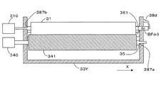
続いて、現像ローラ31および塗布ローラ34の構成および動作について、図5を参照しつつ、さらに詳しく説明する。塗布ローラ34の表面には、上記したように、該塗布ローラ34の回転方向D2に対して斜めに設けられた複数の溝34aが形成されている。したがって、塗布ローラ34と現像ローラ31とが当接しながら回転することによって、塗布ローラ34および現像ローラ31にはそれぞれ、スラスト力THar,THdrが発生する。そして、この実施形態では、現像ローラ31に発生するスラスト力THdrが向う側と同じ方向に現像ローラ31を付勢するバイアス付与接点38b(本発明の「現像剤担持体用付勢部材」に相当)が、接点支持部材381に支持されて配設されている(図5参照)。なお、このバイアス付与接点38bは、現像バイアス発生部114と電気的に接続されており、現像バイアス発生部114はバイアス付与接点38bを介して、現像ローラ31に現像バイアスを印加することができる。また、図5に示すように、本実施形態におけるバイアス付与接点38bは板ばねで構成されている。また、本実施形態におけるバイアス付与接点38bが有する付勢力BFdrは、現像ローラ31と感光体11Yとの間に作用する静止摩擦力と、現像ローラ31と塗布ローラ34との間に作用する静止摩擦力との和よりも大きくなるように構成している。
Next, the configuration and operation of the developing
また、現像ローラ31および塗布ローラ34は、それぞれの回転軸が、タンク33Yに設けられた孔に挿通されることによって、回転自在にタンク33Yに配設されている。そして、(−X)側のタンク33Yの側壁の外側の現像ローラ31の回転軸の所定の位置にはEリング382bが取り付けられている。そして、Eリング382bがタンク33Yの側壁に当接することによって、現像ローラ31を所定の位置(本発明の「現像剤担持体係止位置」に相当)に係止することができる。このように、Eリング382bが本発明の「現像剤担持体用位置決め部」として機能している。一方、(+X)側のタンク33Yの側壁の外側の塗布ローラ34の回転軸の所定の位置にはEリング382aが取り付けられている。そして、Eリング382aがタンク33Yの側壁に当接することによって、塗布ローラ34を所定の位置(本発明の「塗布ローラ係止位置」に相当)に係止することができる。このように、Eリング382aが本発明の「塗布ローラ用位置決め部」として機能している。
The developing
ところで、本実施形態では、現像ローラ31は、製造誤差や組立性などを考慮してスラスト方向に遊びが生じるように設計されており、該スラスト方向に移動自在となっている。そのため、現像ローラ31に対してスラスト方向の外力が印加されると、移動することとなる。したがって、現像工程時に現像ローラ31および塗布ローラ34が当接しながら回転してスラスト力THdrが発生するのに伴い、現像ローラ31はスラスト力THdrが向う側へ移動しようとする。そこで、本実施形態では、現像ローラ31にバイアス付与接点38bにより付勢力BFdrを与えることで、現像ローラ31が移動するのを防止している。現像ローラ31に付勢力BFdrを作用させることで、現像ローラ31が移動するのを防止する様子について以下に詳述する。
By the way, in the present embodiment, the developing
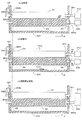
a)回転前
バイアス付与接点38bによって現像ローラ31に与えられる付勢力BFdrは、現像ローラ31と感光体11Yとの間に作用する静止摩擦力と、現像ローラ31と塗布ローラ34との間に作用する静止摩擦力との和よりも大きい。そのため、現像ローラ31はバイアス付与接点38bからの付勢力BFdrによって、Eリング382bがタンク33Yに当接するまで(+X)側へ移動することができる。そして、現像ローラ31はEリング382bにより所定の位置で係止される。また、この実施形態では、塗布ローラ34も、Eリング382aにより所定の位置で係止されている(図5(a)参照)。
a) Before rotation The biasing force BFdr applied to the developing
b)回転中
塗布ローラ34および現像ローラ31が当接しながら回転することによって、塗布ローラ34および現像ローラ31のそれぞれにスラスト力THar,THdrが発生する。現像ローラ31に発生したスラスト力THdrが向う側は付勢力BFdrの方向と同じである。そのため、これらスラスト力THdrと付勢力BFdrの2つの力が現像ローラ31に作用することによって、現像ローラ31はEリング382bにより、より強固に係止される。この際、塗布ローラ34もEリング382aにより係止されており、移動しない(図5(b)参照)。
b) During rotation As the
c)回転停止直後
塗布ローラ34および現像ローラ31が回転停止するのに伴い、それぞれのローラに発生していたスラスト力THar,THdrは消失する(図5(c))。しかしながら、現像ローラ31にはバイアス付与接点38bによる(+X)方向へ付勢力BFdrが作用しており、現像ローラ31はEリング382bにより係止され、移動しない。
c) Immediately after the rotation stops As the
以上のように、この実施形態では、現像ローラ31をスラスト方向における所定の位置(現像剤担持体係止位置)で係止するEリング382b(現像剤担持体用位置決め部)を設けるとともに、塗布ローラ34と現像ローラ31とが当接しながら回転することによって発生するスラスト力THdrにより現像ローラ31が移動しようとする方向と同じ方向に、バイアス付与接点38b(現像剤担持体用付勢部材)によって現像ローラ31を付勢している。また、バイアス付与接点38bが有する付勢力BFdrは、現像ローラ31と感光体11Yとの間に作用する静止摩擦力と、現像ローラ31と塗布ローラ34との間に作用する静止摩擦力との和よりも大きくなるように構成している。そのため、例えば、本実施形態のように現像ローラ31が製造誤差や組立性などを考慮してスラスト方向に遊びが生じるように設計されており、該スラスト方向に移動自在となっている場合でも、バイアス付与接点38b(現像剤担持体用付勢部材)が有する付勢力のみで、現像ローラ31を所定の位置(現像剤担持体係止位置)に移動させて、Eリング38b(現像剤担持体用位置決め部)により係止することができる。そのため、装置組立時において、現像ローラ31は所定の位置へ位置決めされる。したがって、現像動作時に現像ローラ31にスラスト力THdrが発生した際に、現像ローラ31は既に所定の位置でEリング382bにより係止されており、現像ローラ31に発生したスラスト力THdrによって、該現像ローラ31がさらに移動することはない。また、現像ローラ31は、バイアス付与接点38bが有する付勢力BFdrおよびスラスト力THdrの2つの力が作用することにより、スラスト方向における所定の位置でEリング382bにより強固に係止される。したがって、現像動作時に、例えば、振動によって装置が傾いたりしたとしても、現像ローラ31が所定の位置から移動してしまうのを確実に防止することができる。また、現像動作開始直後から、現像ローラ31を所定の位置に確実に係止させることができるため、より効率よく、現像動作時における感光体および塗布ローラ34に対する現像ローラ31の移動を防止して現像精度の向上を図ることができる。
As described above, in this embodiment, the E-ring 382b (developer carrier positioning portion) that locks the developing
また、本発明における付勢部材をバイアス付与接点38b(板ばね)で構成している。したがって、現像ローラ31にバイアスを付与する接点と付勢部材とを兼用することができるので、部品数を削減でき、装置構成を簡素化することができる。
Further, the biasing member in the present invention is constituted by a
また、塗布ローラ34は、その表面に溝が形成されたアニロクスローラであって、溝34aに現像液32を担持することによって現像液32を搬送する構成としている。したがって、塗布ローラ34(アニロクスローラ)の溝34aで現像液32を担持することによって、一定量に計量した現像液32を現像ローラ31に塗布することができる。よって、現像ローラ31に精度よく均一に現像液32を塗布することができる。このように、現像液32が均一に塗布された現像ローラ31が感光体に当接して、該感光体上の静電潜像を現像することによって、該静電潜像の現像精度を向上させることができる。
The
<第2実施形態>
図6は本発明にかかる画像形成装置の第2実施形態において図2の矢印Aの方向から見た現像部の模式図である。この第2実施形態が第1実施形態と大きく相違する点は、本発明の塗布ローラ用付勢部材として、バイアス付与接点38aを塗布ローラ34に設けるとともに、ローラ駆動モータ310,340を、現像ローラ31および塗布ローラ34の(−X)側に設けている点であり、その他の構成は第1実施形態と同様である。以下、第1実施形態との相違点を中心に第2実施形態について詳細に述べる。なお、第1実施形態と同一な構成および動作については、その構成および動作の説明を省略する。
<Second Embodiment>
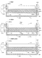
FIG. 6 is a schematic diagram of the developing unit viewed from the direction of arrow A in FIG. 2 in the second embodiment of the image forming apparatus according to the present invention. The second embodiment is greatly different from the first embodiment in that a
塗布ローラ34の表面には、第1実施形態と同様に、該塗布ローラ34の回転方向D2に対して斜めに設けられた複数の溝34aが形成されている。したがって、塗布ローラ34と現像ローラ31とが当接しながら回転することによって、塗布ローラ34および現像ローラ31にはそれぞれ、スラスト力THar,THdrが発生する。そして、この実施形態では、塗布ローラ34に発生するスラスト力THarが向う側と同じ方向に塗布ローラ34を付勢するバイアス付与接点38aが、接点支持部材381に支持されて配設されている(図6参照)。なお、このバイアス付与接点38aは、塗布バイアス発生部(図示省略)と電気的に接続されており、塗布バイアス発生部はバイアス付与接点38aを介して、塗布ローラ34に塗布バイアスを印加することができる。そして、塗布ローラ34に塗布バイアスを印加することによって、塗布ローラ34に担持された現像液32に含まれるトナー粒子を、該現像液32の表層側に移動させて、塗布ローラ34から現像ローラ31への現像液32の塗布効率を向上させたりすることができる。また、図6に示すように、本実施形態におけるバイアス付与接点38aは板ばねで構成されている。また、本実施形態におけるバイアス付与接点38aが有する付勢力BFarは、現像ローラ31と塗布ローラ34との間に作用する静止摩擦力よりも大きくなるように構成している。
On the surface of the
また、現像ローラ31および塗布ローラ34は、それぞれの回転軸が、タンク33Yに設けられた孔に挿通されることによって、回転自在にタンク33Yに配設されている。そして、(−X)側のタンク33Yの側壁の外側の現像ローラ31の回転軸の所定の位置にはEリング382bが取り付けられている。そして、Eリング382bがタンク33Yの側壁に当接することによって、現像ローラ31を所定の位置(本発明の「現像剤担持体係止位置」に相当)に係止することができる。このように、Eリング382bが本発明の「現像剤担持体用位置決め部」として機能している。一方、(+X)側のタンク33Yの側壁の外側の塗布ローラ34の回転軸の所定の位置にはEリング382aが取り付けられている。そして、Eリング382aがタンク33Yの側壁に当接することによって、塗布ローラ34を所定の位置(本発明の「塗布ローラ係止位置」に相当)に係止することができる。このように、Eリング382aが本発明の「塗布ローラ用位置決め部」として機能している。
The developing
ところで、本実施形態では、塗布ローラ34は、製造誤差や組立性などを考慮してスラスト方向に遊びが生じるように設計されており、該スラスト方向に移動自在となっている。そのため、塗布ローラ34に対してスラスト方向の外力が印加されると、移動することとなる。したがって、現像工程時に現像ローラ31および塗布ローラ34が当接しながら回転してスラスト力THarが発生するのに伴い、塗布ローラ34はスラスト力THarが向う側へ移動しようとする。そこで、本実施形態では、塗布ローラ34にバイアス付与接点38aにより付勢力BFarを与えることで、塗布ローラ34が移動するのを防止している。塗布ローラ34に付勢力BFarを作用させることで、塗布ローラ34が移動するのを防止する様子について以下に詳述する。
By the way, in this embodiment, the
a)回転前
バイアス付与接点38aによって塗布ローラ34に与えられる付勢力BFarは、現像ローラ31と塗布ローラ34との間に作用する静止摩擦力よりも大きい。そのため、塗布ローラ34はバイアス付与接点38aからの付勢力BFarによって、Eリング382aがタンク33Yに当接するまで(−X)側へ移動することができる。そして、塗布ローラ34はEリング382aにより所定の位置で係止される。また、この実施形態では、現像ローラ31も、Eリング382bにより所定の位置で係止されている(図6(a)参照)。
a) Before rotation The biasing force BFar applied to the
b)回転中
塗布ローラ34および現像ローラ31が当接しながら回転することによって、塗布ローラ34および現像ローラ31のそれぞれにスラスト力THar,THdrが発生する。塗布ローラ34に発生したスラスト力THarが向う側は付勢力BFarの方向と同じである。そのため、これらスラスト力THarと付勢力BFarの2つの力が塗布ローラ34に作用することによって、塗布ローラ34はEリング382aにより、より強固に係止される。この際、現像ローラ31もEリング382bにより係止されており、移動しない(図6(b)参照)。
b) During rotation As the
c)回転停止直後
塗布ローラ34および現像ローラ31が回転停止するのに伴い、それぞれのローラに発生していたスラスト力THar,THdrは消失する(図6(c))。しかしながら、塗布ローラ34にはバイアス付与接点38aによる(−X)方向へ付勢力BFarが作用しており、塗布ローラ34はEリング382aにより係止され、移動しない。
c) Immediately after the rotation stops As the
この第2実施形態では、塗布ローラ34をスラスト方向における所定の位置(塗布ローラ係止位置)で係止するEリング382a(塗布ローラ用位置決め部)を設けるとともに、塗布ローラ34と現像ローラ31とが当接しながら回転することによって発生するスラスト力THarにより塗布ローラ34が移動しようとする方向と同じ方向に、バイアス付与接点38a(塗布ローラ用付勢部材)によって塗布ローラ34を付勢している。また、バイアス付与接点38aが有する付勢力BFarは、現像ローラ31と塗布ローラ34との間に作用する静止摩擦力よりも大きくなるように構成している。そのため、例えば、本実施形態のように塗布ローラ34が製造誤差や組立性などを考慮してスラスト方向に遊びが生じるように設計されており、該スラスト方向に移動自在となっている場合でも、バイアス付与接点38a(塗布ローラ用付勢部材)が有する付勢力のみで、塗布ローラ34を所定の位置(塗布ローラ係止位置)に移動させて、Eリング38a(塗布ローラ用位置決め部)により係止することができる。そのため、装置組立時において、塗布ローラ34は所定の位置へ位置決めされる。したがって、現像動作時に塗布ローラ34にスラスト力THarが発生した際に、塗布ローラ34は既に所定の位置でEリング382aにより係止されており、塗布ローラ34に発生したスラスト力THarによって、該塗布ローラ34がさらに移動することはない。また、塗布ローラ34は、バイアス付与接点38aが有する付勢力BFarおよびスラスト力THarの2つの力が作用することにより、スラスト方向における所定の位置でEリング382aにより強固に係止される。したがって、現像動作時に、例えば、振動によって装置が傾いたりしたとしても、塗布ローラ34が所定の位置から移動してしまうのを確実に防止することができる。また、現像動作開始直後から、塗布ローラ34を所定の位置に確実に係止させることができるため、より効率よく、現像動作時における現像ローラ31に対する塗布ローラ34の移動を防止して、現像ローラ31に塗布する現像液32の塗布パターンが乱れるのを防止することができる。このように、該塗布パターンが乱れた現像ローラ31上の現像液32で、感光体上の静電潜像を現像するのを防止することができるので、現像精度が劣化するのを防止して、現像精度の向上を図ることができる。
In the second embodiment, an E-ring 382a (application roller positioning portion) that locks the
<第3実施形態>
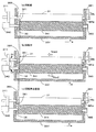
図7は本発明にかかる画像形成装置の第3実施形態において図2の矢印Aの方向から見た現像部の模式図である。この第3実施形態が第1および第2実施形態と大きく相違する点は、本発明の現像剤担持体用付勢部材としてバイアス付与接点38bを現像ローラ31に設けるとともに、本発明の塗布ローラ用付勢部材としてバイアス付与接点38aを塗布ローラ34に設けている点である。そして、ローラ駆動モータ310を現像ローラ31の(+X)側に、ローラ駆動モータ340を塗布ローラ34の(−X)側に設けている。また、本発明の現像剤担持体用位置決め部としてのEリング383b、本発明の塗布ローラ用位置決め部としてのEリング383aを、それぞれタンク33Yの内側に設けている。その他の構成は、第1および第2実施形態と同様である。以下、第1および第2実施形態との相違点を中心に第3実施形態について詳細に述べる。なお、第1および第2実施形態と同一な構成および動作については、その構成および動作の説明を省略する。
<Third Embodiment>
FIG. 7 is a schematic diagram of the developing unit viewed from the direction of arrow A in FIG. 2 in the third embodiment of the image forming apparatus according to the present invention. The third embodiment is greatly different from the first and second embodiments in that a
塗布ローラ34の表面には、第1および第2実施形態と同様に、該塗布ローラ34の回転方向D2に対して斜めに設けられた複数の溝34aが形成されている。したがって、塗布ローラ34と現像ローラ31とが当接しながら回転することによって、塗布ローラ34および現像ローラ31にはそれぞれ、スラスト力THar,THdrが発生する。そして、この実施形態では、塗布ローラ34に発生するスラスト力THarが向う側と同じ方向に塗布ローラ34を付勢するバイアス付与接点38aが、接点支持部材381に支持されて配設されている。また、現像ローラ31に発生するスラスト力THdrが向う側と同じ方向に現像ローラ31を付勢するバイアス付与接点38bが、接点支持部材381に支持されて配設されている(図7参照)。
On the surface of the
なお、このバイアス付与接点38a,38bは、上記第1および第2実施形態と同様に、塗布バイアス発生部(図示省略)および現像バイアス発生部114と電気的に接続されている。したがって、塗布バイアス発生部はバイアス付与接点38aを介して塗布ローラ34に塗布バイアスを印加することができ、現像バイアス発生部114はバイアス付与接点38bを介して現像ローラ31に現像バイアスを印加することができる。また、図7に示すように、上記第1および第2実施形態と同様に、本実施形態におけるバイアス付与接点38a,38bは板ばねで構成されている。また、本実施形態におけるバイアス付与接点38aが有する付勢力BFarは、現像ローラ31と塗布ローラ34との間に作用する静止摩擦力よりも大きくなるように構成している。一方、本実施形態におけるバイアス付与接点38bが有する付勢力BFdrは、現像ローラ31と感光体11Yとの間に作用する静止摩擦力と、現像ローラ31と塗布ローラ34との間に作用する静止摩擦力との和よりも大きくなるように構成している。
The
また、現像ローラ31および塗布ローラ34は、それぞれの回転軸が、タンク33Yに設けられた孔に挿通されることによって、回転自在にタンク33Yに配設されている。そして、(+X)側のタンク33Yの側壁の内側の現像ローラ31の回転軸の所定の位置にはEリング383bが取り付けられている。そして、Eリング383bがタンク33Yの内壁に当接することによって、現像ローラ31を所定の位置(本発明の「現像剤担持体係止位置」に相当)に係止することができる。このように、Eリング383bが本発明の「現像剤担持体用位置決め部」として機能している。一方、(−X)側のタンク33Yの側壁の内側の塗布ローラ34の回転軸の所定の位置にはEリング383aが取り付けられている。そして、Eリング383aがタンク33Yの内壁に当接することによって、塗布ローラ34を所定の位置(本発明の「塗布ローラ係止位置」に相当)に係止することができる。このように、Eリング383aが本発明の「塗布ローラ用位置決め部」として機能している。
The developing
ところで、本実施形態では、塗布ローラ34および現像ローラ31は、製造誤差や組立性などを考慮してスラスト方向に遊びが生じるように設計されており、該スラスト方向に移動自在となっている。そのため、塗布ローラ34および現像ローラ31に対してスラスト方向の外力が印加されると、移動することとなる。したがって、現像工程時に現像ローラ31および塗布ローラ34が当接しながら回転してスラスト力THar,THdrが発生するのに伴い、塗布ローラ34および現像ローラ31はスラスト力THar,THdrが向う側へ移動しようとする。そこで、本実施形態では、塗布ローラ34および現像ローラ31にバイアス付与接点38a,38bにより付勢力BFar,BFdrを与えることで、塗布ローラ34および現像ローラ31が移動するのを防止している。塗布ローラ34および現像ローラ31に付勢力BFar,BFdrを作用させることで、塗布ローラ34および現像ローラ31が移動するのを防止する様子について以下に詳述する。
By the way, in the present embodiment, the
a)回転前
バイアス付与接点38aによって塗布ローラ34に与えられる付勢力BFarは、現像ローラ31と塗布ローラ34との間に作用する静止摩擦力よりも大きい。そのため、塗布ローラ34はバイアス付与接点38aからの付勢力BFarによって、Eリング383aがタンク33Yに当接するまで(−X)側へ移動することができる。そして、塗布ローラ34はEリング383aにより所定の位置で係止される。また、バイアス付与接点38bによって現像ローラ31に与えられる付勢力BFdrは、現像ローラ31と感光体11Yとの間に作用する静止摩擦力と、現像ローラ31と塗布ローラ34との間に作用する静止摩擦力との和よりも大きい。そのため、現像ローラ31はバイアス付与接点38bからの付勢力BFdrによって、Eリング383bがタンク33Yに当接するまで(+X)側へ移動することができる。そして、現像ローラ31はEリング383bにより所定の位置で係止される(図7(a)参照)。
a) Before rotation The biasing force BFar applied to the
b)回転中
塗布ローラ34および現像ローラ31が当接しながら回転することによって、塗布ローラ34および現像ローラ31のそれぞれにスラスト力THar,THdrが発生する。塗布ローラ34に発生したスラスト力THarが向う側は付勢力BFarの方向と同じである。そのため、これらスラスト力THarと付勢力BFarの2つの力が塗布ローラ34に作用することによって、塗布ローラ34はEリング383aにより、より強固に係止される。また、現像ローラ31に発生したスラスト力THdrが向う側は付勢力BFdrの方向と同じである。そのため、これらスラスト力THdrと付勢力BFdrの2つの力が現像ローラ31に作用することによって、現像ローラ31はEリング383bにより、より強固に係止される(図7(b)参照)。
b) During rotation As the
c)回転停止直後
塗布ローラ34および現像ローラ31が回転停止するのに伴い、それぞれのローラに発生していたスラスト力THar,THdrは消失する(図6(c))。しかしながら、塗布ローラ34にはバイアス付与接点38aによる(−X)方向へ付勢力BFarが作用しており、塗布ローラ34はEリング383aにより係止され、移動しない。また、現像ローラ31にはバイアス付与接点38bによる(+X)方向へ付勢力BFdrが作用しており、現像ローラ31はEリング383bにより係止され、移動しない。
c) Immediately after the rotation stops As the
この第3実施形態では、塗布ローラ34をスラスト方向における所定の位置(塗布ローラ係止位置)で係止するEリング383a(塗布ローラ用位置決め部)を設けるとともに、スラスト力により塗布ローラ34が移動しようとする方向と同じ方向に、バイアス付与接点38a(塗布ローラ用付勢部材)によって塗布ローラ34を付勢している。一方、現像ローラ31をスラスト方向における所定の位置(現像剤担持体係止位置)で係止するEリング383b(現像剤担持体用位置決め部)を設けるとともに、スラスト力により現像ローラ31が移動しようとする方向と同じ方向に、バイアス付与接点38b(現像剤担持体用付勢部材)によって現像ローラ31を付勢している。そのため、上記第1および第2実施形態における作用効果を同時に奏することができる。
In the third embodiment, an E-ring 383a (application roller positioning portion) that locks the
<第4実施形態>
図8は本発明にかかる画像形成装置の第4実施形態において図2の矢印Aの方向から見た現像部の模式図である。この第4実施形態が第1実施形態と大きく相違する点は、塗布ローラ341と現像ローラ31とが当接しながら回転することによって発生するスラスト力の向う側が、上記第1実施形態の方向と反対の方向になるように、塗布ローラ341に溝34aを形成している点である。また、本発明の現像剤担持体用位置決め部としてピン384を、本発明の塗布ローラ用位置決め部としてカバー385を設けている。また、ロータ駆動モータ340を塗布ローラ341にのみ設け、現像ローラ31にはロータ駆動モータ340の駆動力を受けることのできるギア311を設けている。その他の構成は第1実施形態と同様である。以下、第1実施形態との相違点を中心に第4実施形態について詳細に述べる。なお、第1実施形態と同一な構成および動作については、その構成および動作の説明を省略する。
<Fourth embodiment>
FIG. 8 is a schematic diagram of the developing unit viewed from the direction of arrow A in FIG. 2 in the fourth embodiment of the image forming apparatus according to the present invention. The fourth embodiment differs greatly from the first embodiment in that the side to which the thrust force generated by the
塗布ローラ341の表面には、第1実施形態とは逆向きに、該塗布ローラ341の回転方向D2に対して斜めに設けられた複数の溝34aが形成されている。したがって、塗布ローラ341と現像ローラ31とが当接しながら回転することによって、塗布ローラ341および現像ローラ31にはそれぞれ、スラスト力THar2,THdr2が発生する。そして、この実施形態では、現像ローラ31に発生するスラスト力THdr2が向う側と同じ方向に現像ローラ31を付勢するバイアス付与接点38b(本発明の「現像剤担持体用付勢部材」に相当)が、接点支持部材381に支持されて配設されている(図8参照)。なお、このバイアス付与接点38bは、現像バイアス発生部114と電気的に接続されており、現像バイアス発生部114はバイアス付与接点38bを介して、現像ローラ31に現像バイアスを印加することができる。また、図8に示すように、本実施形態におけるバイアス付与接点38bは板ばねで構成されている。また、本実施形態におけるバイアス付与接点38bが有する付勢力BFdrは、現像ローラ31と感光体11Yとの間に作用する静止摩擦力と、現像ローラ31と塗布ローラ341との間に作用する静止摩擦力との和よりも大きくなるように構成している。
On the surface of the
また、現像ローラ31および塗布ローラ341は、それぞれの回転軸が、タンク33Yに設けられた孔に挿通されることによって、回転自在にタンク33Yに配設されている。そして、(−X)側のタンク33Yの側壁の内側の現像ローラ31の回転軸の所定の位置にはピン384が嵌挿されている。そして、ピン384がタンク33Yの内壁に当接することによって、現像ローラ31を所定の位置(本発明の「現像剤担持体係止位置」に相当)に係止することができる。このように、ピン384が本発明の「現像剤担持体用位置決め部」として機能している。一方、(+X)側のタンク33Yの側壁の外側の塗布ローラ341の回転軸の端部を覆うようにカバー385がタンク33Yに配設されている。そして、塗布ローラ341の(+X)側の端部がカバー385の内側に当接することによって、塗布ローラ341を所定の位置(本発明の「塗布ローラ係止位置」に相当)に係止することができる。このように、カバー385が本発明の「塗布ローラ用位置決め部」として機能している。
The developing
また、現像ローラ31の(−X)側には、ローラ駆動モータの換わりにギア311が軸着されている。このギア311は、ローラ駆動モータ340からの駆動力を受けることによって回転する。そして、ギア311が回転することによって、現像ローラ31が回転する。
A
ところで、本実施形態では、現像ローラ31は、製造誤差や組立性などを考慮してスラスト方向に遊びが生じるように設計されており、該スラスト方向に移動自在となっている。そのため、現像ローラ31に対してスラスト方向の外力が印加されると、移動することとなる。したがって、現像工程時に現像ローラ31および塗布ローラ341が当接しながら回転してスラスト力THdr2が発生するのに伴い、現像ローラ31はスラスト力THdr2が向う側へ移動しようとする。そこで、本実施形態では、現像ローラ31にバイアス付与接点38bにより付勢力BFdrを与えることで、現像ローラ31が移動するのを防止している。現像ローラ31に付勢力BFdrを作用させることで、現像ローラ31が移動するのを防止する様子について以下に詳述する。
By the way, in the present embodiment, the developing
a)回転前
バイアス付与接点38bによって現像ローラ31に与えられる付勢力BFdrは、現像ローラ31と感光体11Yとの間に作用する静止摩擦力と、現像ローラ31と塗布ローラ341との間に作用する静止摩擦力との和よりも大きい。そのため、現像ローラ31はバイアス付与接点38bからの付勢力BFdrによって、ピン384がタンク33Yに当接するまで(−X)側へ移動することができる。そして、現像ローラ31はピン384により所定の位置で係止される。また、この実施形態では、塗布ローラ341も、カバー385により所定の位置で係止されている(図8(a)参照)。
a) Before rotation The biasing force BFdr applied to the developing
b)回転中
塗布ローラ341および現像ローラ31が当接しながら回転することによって、塗布ローラ341および現像ローラ31のそれぞれにスラスト力THa2,THdr2が発生する。現像ローラ31に発生したスラスト力THdr2が向う側は付勢力BFdrの方向と同じである。そのため、これらスラスト力THdr2と付勢力BFdrの2つの力が現像ローラ31に作用することによって、現像ローラ31はピン384により、より強固に係止される。この際、塗布ローラ341もカバー385により係止されており、移動しない(図8(b)参照)。
b) During rotation As the
c)回転停止直後
塗布ローラ341および現像ローラ31が回転停止するのに伴い、それぞれのローラに発生していたスラスト力THar2,THdr2は消失する(図8(c))。しかしながら、現像ローラ31にはバイアス付与接点38bによる(−X)方向へ付勢力BFdrが作用しており、現像ローラ31はピン384により係止され、移動しない。
c) Immediately after the rotation stops As the
この第4実施形態では、現像ローラ31をスラスト方向における所定の位置(現像剤担持体係止位置)で係止するピン384(現像剤担持体用位置決め部)を設けるとともに、塗布ローラ341と現像ローラ31とが当接しながら回転することによって発生するスラスト力THdr2により現像ローラ31が移動しようとする方向と同じ方向に、バイアス付与接点38b(現像剤担持体用付勢部材)によって現像ローラ31を付勢している。また、バイアス付与接点38bが有する付勢力BFdrは、現像ローラ31と感光体11Yとの間に作用する静止摩擦力と、現像ローラ31と塗布ローラ341との間に作用する静止摩擦力との和よりも大きくなるように構成している。そのため、例えば、本実施形態のように現像ローラ31が製造誤差や組立性などを考慮してスラスト方向に遊びが生じるように設計されており、該スラスト方向に移動自在となっている場合に、上記第1実施形態と同様の作用効果を奏することができる。
In the fourth embodiment, a pin 384 (developer carrier positioning portion) for locking the developing
<第5実施形態>
図9は本発明にかかる画像形成装置の第5実施形態において図2の矢印Aの方向から見た現像部の模式図である。この第5実施形態が第4実施形態と大きく相違する点は、付勢部材としてバイアス付与接点38bの代わりにコイルばね38cを用いて、現像ローラ31に付勢力BFdr2を与えている点である。また、本発明の現像剤担持体用位置決め部として円盤386を、本発明の塗布ローラ用位置決め部としてEリング382aを設けている。その他の構成は第4実施形態と同様であり、以下、第4実施形態との相違点を中心に第5実施形態について詳細に述べる。なお、第4実施形態と同一な構成および動作については、その構成および動作の説明を省略する。
<Fifth Embodiment>
FIG. 9 is a schematic diagram of the developing unit viewed from the direction of arrow A in FIG. 2 in the fifth embodiment of the image forming apparatus according to the present invention. The fifth embodiment is greatly different from the fourth embodiment in that a biasing force BFdr2 is applied to the developing
現像ローラ31および塗布ローラ34は、それぞれの回転軸が、タンク33Yに設けられた孔に挿通されることによって、回転自在にタンク33Yに配設されている。そして、(+X)側のタンク33Yの側壁の外側の現像ローラ31の回転軸の所定の位置には円盤386が取り付けられている。そして、円盤386がタンク33Yの側壁に当接することによって、現像ローラ31を所定の位置(本発明の「現像剤担持体係止位置」に相当)に係止することができる。このように、円盤386が本発明の「現像剤担持体用位置決め部」として機能している。一方、(−X)側のタンク33Yの側壁の外側の塗布ローラ341の回転軸の所定の位置にはEリング382aが取り付けられている。そして、Eリング382aがタンク33Yの側壁に当接することによって、塗布ローラ341を所定の位置(本発明の「塗布ローラ係止位置」に相当)に係止することができる。このように、Eリング382aが本発明の「塗布ローラ用位置決め部」として機能している。
The developing
塗布ローラ341の表面には、第4実施形態と同様に、該塗布ローラ341の回転方向D2に対して斜めに設けられた複数の溝34aが形成されている。したがって、塗布ローラ341と現像ローラ31とが当接しながら回転することによって、塗布ローラ341および現像ローラ31にはそれぞれ、スラスト力THar2,THdr2が発生する。そして、この実施形態では、現像ローラ31に発生するスラスト力THdr2が向う側と同じ方向に現像ローラ31を付勢するコイルばね38c(本発明の「現像剤担持体用付勢部材」に相当)が設けられている。このコイルばねのコイル部分の直径は現像ローラ31の回転軸の直径よりも大きく構成されており、該回転軸に取り付けられた円盤386に付勢力BFdr2を与えることが出来るように構成されている(図9参照)。このように、円盤386を付勢することによって、円盤386が取り付けられている現像ローラ31を付勢することができる。なお、本実施形態におけるコイルばね38cが有する付勢力BFdr2は、現像ローラ31と感光体11Yとの間に作用する静止摩擦力と、現像ローラ31と塗布ローラ341との間に作用する静止摩擦力との和よりも大きくなるように構成している。
On the surface of the
この第5実施形態では、現像ローラ31をスラスト方向における所定の位置(現像剤担持体係止位置)で係止する円盤386(現像剤担持体用位置決め部)を設けるとともに、塗布ローラ341と現像ローラ31とが当接しながら回転することによって発生するスラスト力THdr2により現像ローラ31が移動しようとする方向と同じ方向に、コイルばね38c(現像剤担持体用付勢部材)によって現像ローラ31を付勢している。また、コイルばね38cが有する付勢力BFdr2は、現像ローラ31と感光体11Yとの間に作用する静止摩擦力と、現像ローラ31と塗布ローラ341との間に作用する静止摩擦力との和よりも大きくなるように構成している。そのため、例えば、第4実施形態のように現像ローラ31が製造誤差や組立性などを考慮してスラスト方向に遊びが生じるように設計されており、該スラスト方向に移動自在となっている場合に、上記第4実施形態と同様の作用効果を奏することができる。
In the fifth embodiment, a disk 386 (developer carrier positioning portion) for locking the developing
<第6実施形態>
図10は本発明にかかる画像形成装置の第6実施形態において図2の矢印Aの方向から見た現像部の模式図である。この第6実施形態が第4実施形態と大きく相違する点は、付勢部材としてバイアス付与接点38aの換わりに板ばね38dを用いて、現像ローラ31に付勢力BFdr3を与えている点である。この付勢力BFdr3の大きさは、現像ローラ31と感光体11Yとの間に作用する静止摩擦力と、現像ローラ31と塗布ローラ341との間に作用する静止摩擦力との和よりも大きくなるように構成している。また、この板ばね38dの形状は図10に示すように、L字型となっている。また、本発明の現像剤担持体用位置決め部としてフランジ部387bが現像ローラ31の(−X)側の回転軸に形成されている。一方、本発明の塗布ローラ用位置決め部としてフランジ部387aが塗布ローラ341の(+X)側の回転軸に形成されている。その他の構成は第4実施形態と同様であり、上記第4実施形態と同様の作用効果を奏する。
<Sixth Embodiment>
FIG. 10 is a schematic diagram of the developing unit viewed from the direction of arrow A in FIG. 2 in the sixth embodiment of the image forming apparatus according to the present invention. The sixth embodiment is greatly different from the fourth embodiment in that a biasing force BFdr3 is applied to the developing
<第7実施形態>
図11は第7実施形態におけるワイヤーバーを示す模式図である。この実施形態が第1ないし第6実施形態と大きく相違する点は、塗布ローラとして、アニロクスローラの代わりにワイヤーバー39を用いている点であり、その他の構成は第1ないし第6実施形態と同様である。以下、第1ないし第6実施形態との相違点を中心に第7実施形態について詳細に述べる。なお、第1ないし第6実施形態と同一な構成および動作については、その構成および動作の説明を省略する。
<Seventh embodiment>
FIG. 11 is a schematic view showing a wire bar in the seventh embodiment. The main difference between this embodiment and the first to sixth embodiments is that the
このワイヤーバー39は、芯金に、例えば、線径100μmのワイヤー391を100μmのピッチ感覚で巻きつけることによって構成することができる。ワイヤー391を芯金に巻きつけることによって形成されたワイヤ間の凹部39aは、アニロクスローラ(塗布ローラ34,341)における溝34aと同様の作用効果を有する。
The
このような構成とすれば、ワイヤーバー39の表面粗さは比較的小さいため、ワイヤーバー39と現像ローラ31との当接部における静止摩擦力を小さくすることができる。したがって、ワイヤーバー39と現像ローラ31とを当接させながらスラスト方向に相対的に移動させやすくなる。このため、ワイヤーバーと現像剤担持体とを当接させながら、確実にスラスト方向に移動させることができ、短時間でスラスト方向における所定の係止位置へ移動させることができる。
With such a configuration, since the surface roughness of the
<その他>
なお、本発明は上記実施形態に限定されるものではなく、その趣旨を逸脱しない限りにおいて上述したものに対して種々の変更を加えることが可能である。例えば、上記した実施形態ではいずれも、付勢力のみで、現像ローラ31あるいは塗布ローラ34をスラスト方向に移動可能なように付勢力BFar,BFdr,BFdr2,BFdr3の大きさが設定されている。が、付勢力のみで現像ローラ31または塗布ローラ34をスラスト方向に移動させることができない大きさに付勢力BFar,BFdr,BFdr2,BFdr3を設定しても構わない。例えば、図12に示すように、バイアス付与接点38b2(現像剤担持体用付勢部材)は、現像ローラ31(現像剤担持体)と感光体との間に作用する静止摩擦力と、現像ローラ31と塗布ローラ34との間に作用する静止摩擦力との和SFよりも小さな付勢力BFdr4を有している構成としてもよい。このような構成とすれば、現像動作時に、現像ローラ31をスラスト力THdrとバイアス付与接点38b2の付勢力BFdr4の2つの力によって、短時間でスラスト方向における所定の係止位置に移動させて、Eリング382b(現像剤担持体用位置決め部)により係止することができる。このように、現像ローラ31を短時間で所定の係止位置での係止状態とすることができる。そして、この2つの力THdr,BFdr4によって、現像ローラ31を所定の係止位置でEリング382bにより確実に係止することができる。したがって、現像動作時における感光体および塗布ローラ34に対する現像ローラ31の移動を防止して現像精度の劣化を防止し、現像精度の向上を図ることができる。
<Others>
The present invention is not limited to the above-described embodiment, and various modifications can be made to the above-described one without departing from the spirit of the present invention. For example, in any of the above-described embodiments, the magnitudes of the urging forces BFar, BFdr, BFdr2, and BFdr3 are set so that the developing
また、付勢部材として、第1ないし第4実施形態におけるバイアス付与接点(板ばね)、第5実施形態におけるコイルばね、第6実施形態における板ばねを種々組み合わせた構成としても構わない。 The biasing contact (plate spring) in the first to fourth embodiments, the coil spring in the fifth embodiment, and the plate spring in the sixth embodiment may be variously combined as the biasing member.
また、付勢部材としては、上記した構成以外にも種々の部材で構成することができる。要は、塗布ローラまたは現像剤担持体を確実に付勢することのできる構成であればよい。このような付勢部材としては、例えば、ゴムプッシュで構成することができる。 Moreover, as an urging | biasing member, it can comprise with various members besides the above-mentioned structure. In short, any configuration may be used as long as the application roller or the developer carrying member can be reliably urged. Such an urging member can be constituted by a rubber push, for example.
また、第4ないし第6実施形態において、ローラ駆動モータ310,340、ギア311を逆側の(+X)側に設けて、塗布ローラ341の(−X)側に付勢部材を設ける構成としても構わない。このような構成とすれば、上記第2実施形態と同様の作用効果を奏することができる。
In the fourth to sixth embodiments, the
また、第5および第6実施形態において、第3実施形態と同様に、ローラ駆動モータ340を塗布ローラ341の(+X)側に、ローラ駆動モータ310を現像ローラ31の(−X)側に設けて、付勢部材を、塗布ローラ341の(−X)側と現像ローラ31の(+X)側とに設ける構成としても構わない。このような構成とすれば、上記第3実施形態と同様の作用効果を奏することができる。
In the fifth and sixth embodiments, similarly to the third embodiment, the
また、付勢部材として、第5実施形態におけるコイルばね、第6実施形態に板ばねを他の実施形態で用いてももちろん構わない。 Also, as a biasing member, the coil spring in the fifth embodiment and the leaf spring in the sixth embodiment may be used in other embodiments.
また、第4実施形態におけるローラ駆動方法を他の実施形態で用いても構わない。 The roller driving method in the fourth embodiment may be used in other embodiments.
また、上記実施形態では、ローラ駆動モータが配設されている一方端部と反対側の他方端部から塗布ローラおよび現像ローラを付勢部材によって付勢しているが、ローラ駆動モータが配設されている一方端部から、塗布ローラおよび現像ローラを付勢する構成でももちろん構わない。 In the above embodiment, the application roller and the developing roller are urged by the urging member from the other end opposite to the one end where the roller drive motor is provided, but the roller drive motor is provided. Of course, a configuration in which the application roller and the developing roller are urged from the one end portion of the end may be employed.
また、第5実施形態におけるコイルばね、第6実施形態における板ばねをバイアス付与接点として用いても構わない。 Moreover, you may use the coil spring in 5th Embodiment, and the leaf | plate spring in 6th Embodiment as a bias provision contact.
また、上記実施形態における位置決め部(Eリング、カバー、ピン、円盤、フランジ)は、それぞれ、いずれの実施形態で用いても構わない。また、位置決め部は、確実に現像剤担持体または塗布ローラを係止することのできる構成であれば、どのような構成としても構わない。 Moreover, you may use the positioning part (E ring, a cover, a pin, a disk, a flange) in the said embodiment in any embodiment, respectively. Further, the positioning portion may have any configuration as long as it can reliably lock the developer carrier or the application roller.
また、上記実施形態では、露光部20を各感光体11Y,11M,11C,11Kに1対1に対応して設け、各感光体11Y,11M,11C,11Kのそれぞれに、対応した静電潜像を形成するように構成したが、例えば、1つの露光部を配設し、レーザービームの照射方向をミラー等を用いて切り替えることによって、各感光体11Y,11M,11C,11Kのそれぞれに対応した静電潜像を形成する構成としてもよい。その他、LEDアレイを用いた露光手段を使用したり、いわゆる書込帯電を行う潜像書込み手段を用いても構わない。要は、各感光体11Y,11M,11C,11Kのそれぞれに、1対1に対応した静電潜像を形成できる構成であれば、どのような構成としてもよい。
In the above embodiment, the
また、上記実施形態では、規制ブレード35はトレール規制を行っているが、規制ブレードの35の先端が塗布ローラ34の回転方向の上流側に向くように配置して、いわゆるカウンタ規制を行っても構わない。
In the above-described embodiment, the
また、上記実施形態では、本発明をタンデム方式のカラープリンタに具現化しているが、いわゆる、モノクロプリンタに本発明にかかる構成を適用しても構わない。 In the above embodiment, the present invention is embodied in a tandem color printer. However, the configuration according to the present invention may be applied to a so-called monochrome printer.
また、上記実施形態では、ホストコンピュータなどの外部装置より与えられた画像を転写紙に印刷するプリンタを用いて説明しているが、本発明はこれに限られず、複写機やファクシミリ装置などを含む一般の電子写真方式の画像形成装置に適用することができる。要は、液体キャリアにトナーを分散した液体現像剤を、一旦、塗布ローラで担持したあと、該担持した液体現像剤を現像剤担持体に塗布し、現像剤担持体に塗布された液体現像剤によって、潜像担持体上の静電潜像を現像する画像形成装置全般に本発明を適用することができる。 In the above embodiment, a printer that prints an image provided from an external device such as a host computer on transfer paper is described. However, the present invention is not limited to this, and includes a copying machine, a facsimile machine, and the like. The present invention can be applied to a general electrophotographic image forming apparatus. In short, a liquid developer in which toner is dispersed in a liquid carrier is once carried by an application roller, and then the carried liquid developer is applied to the developer carrier and the liquid developer applied to the developer carrier. Thus, the present invention can be applied to all image forming apparatuses that develop an electrostatic latent image on a latent image carrier.
11…感光体(潜像担持体)、 31…現像ローラ(現像剤担持体)、 32…現像液(液体現像剤)、 34,341…塗布ローラ(アニロクスローラ)、 38a,38b,38b2…バイアス付与接点(付勢部材)、 38c…コイルばね(付勢部材)、 38d…板ばね(付勢部材)、 382a,382b,383a,383b…Eリング(位置決め部)、 384…ピン(位置決め部)、 385…カバー(位置決め部)、 386…円盤(位置決め部)、 387a,387b…フランジ(位置決め部)、 39…ワイヤーバー、 D2…第1方向、 BFar,BFdr,BFdr2,BFdr3,BFdr4…付勢力、 THdr,THdr2,THar,THar2…スラスト力、 SF…摩擦力
DESCRIPTION OF
Claims (4)
回転方向に対して斜めに設けられた溝を有しており、前記溝に液体現像剤を担持しながら前記現像剤担持体と接触する位置に搬送して該液体現像剤を前記現像剤担持体に塗布する塗布ローラと、
前記現像剤担持体を前記塗布ローラの回転方向に直交もしくはほぼ直交するスラスト方向における現像剤担持体係止位置で係止する現像剤担持体用位置決め部と、
前記塗布ローラと前記現像剤担持体とが当接しながら回転することによって発生するスラスト力により前記現像剤担持体が移動する方向に、前記現像剤担持体を付勢する現像剤担持体用付勢部材と、
を備えたことを特徴とする液体現像装置。 A developer carrier;
A groove provided obliquely with respect to the rotation direction, and the liquid developer is conveyed to a position in contact with the developer carrier while carrying the liquid developer in the groove and the developer carrier; An application roller to apply to
A developer carrier positioning portion for locking the developer carrier at a developer carrier locking position in a thrust direction orthogonal or substantially orthogonal to the rotation direction of the application roller;
Energizing the developer carrier for biasing the developer carrier in a direction in which the developer carrier moves due to a thrust force generated by the application roller and the developer carrier rotating in contact with each other. Members,
A liquid developing apparatus comprising:
前記スラスト力により前記塗布ローラが移動する方向に、前記塗布ローラを付勢する塗布ローラ用付勢部材と
を備えた請求項1または2記載の液体現像装置。 A coating roller positioning portion for locking the coating roller at a coating roller locking position in the thrust direction;
The liquid developing device according to claim 1, further comprising: an application roller urging member that urges the application roller in a direction in which the application roller moves by the thrust force.
前記潜像担持体と接触して液体現像剤を現像する現像剤担持体と、
回転方向に対して斜めに設けられた溝を有しており、前記溝に液体現像剤を担持しながら前記現像剤担持体と接触する位置に搬送して該液体現像剤を前記現像剤担持体に塗布する塗布ローラと、
前記現像剤担持体を前記塗布ローラの回転方向に直交もしくはほぼ直交するスラスト方向における現像剤担持体係止位置で係止する現像剤担持体用位置決め部と、
前記塗布ローラと前記現像剤担持体とが当接しながら回転することによって発生するスラスト力により前記現像剤担持体が移動する方向に、前記現像剤担持体を付勢する現像剤担持体用付勢部材と、
を備えたことを特徴とする画像形成装置。 A latent image carrier;
A developer carrier for developing a liquid developer in contact with the latent image carrier;
A groove provided obliquely with respect to the rotation direction, and the liquid developer is conveyed to a position in contact with the developer carrier while carrying the liquid developer in the groove and the developer carrier; An application roller to apply to
A developer carrier positioning portion for locking the developer carrier at a developer carrier locking position in a thrust direction orthogonal or substantially orthogonal to the rotation direction of the application roller;
Energizing the developer carrier for biasing the developer carrier in a direction in which the developer carrier moves due to a thrust force generated by the application roller and the developer carrier rotating in contact with each other. Members,
An image forming apparatus comprising:
Priority Applications (1)
| Application Number | Priority Date | Filing Date | Title |
|---|---|---|---|
| JP2004274501A JP4635537B2 (en) | 2004-09-22 | 2004-09-22 | Liquid developing device and image forming apparatus |
Applications Claiming Priority (1)
| Application Number | Priority Date | Filing Date | Title |
|---|---|---|---|
| JP2004274501A JP4635537B2 (en) | 2004-09-22 | 2004-09-22 | Liquid developing device and image forming apparatus |
Related Child Applications (1)
| Application Number | Title | Priority Date | Filing Date |
|---|---|---|---|
| JP2010220956A Division JP4858642B2 (en) | 2010-09-30 | 2010-09-30 | Liquid developing device and image forming apparatus |
Publications (3)
| Publication Number | Publication Date |
|---|---|
| JP2006091218A JP2006091218A (en) | 2006-04-06 |
| JP2006091218A5 JP2006091218A5 (en) | 2007-11-08 |
| JP4635537B2 true JP4635537B2 (en) | 2011-02-23 |
Family
ID=36232303
Family Applications (1)
| Application Number | Title | Priority Date | Filing Date |
|---|---|---|---|
| JP2004274501A Expired - Fee Related JP4635537B2 (en) | 2004-09-22 | 2004-09-22 | Liquid developing device and image forming apparatus |
Country Status (1)
| Country | Link |
|---|---|
| JP (1) | JP4635537B2 (en) |
Citations (2)
| Publication number | Priority date | Publication date | Assignee | Title |
|---|---|---|---|---|
| JP2000122446A (en) * | 1998-10-19 | 2000-04-28 | Ricoh Co Ltd | Transfer carrying device |
| JP2004012523A (en) * | 2002-06-03 | 2004-01-15 | Canon Inc | Developing device, developing cartridge, process cartridge, and image forming apparatus |
Family Cites Families (1)
| Publication number | Priority date | Publication date | Assignee | Title |
|---|---|---|---|---|
| JPH11174851A (en) * | 1997-12-05 | 1999-07-02 | Ricoh Co Ltd | Developing device |
-
2004
- 2004-09-22 JP JP2004274501A patent/JP4635537B2/en not_active Expired - Fee Related
Patent Citations (2)
| Publication number | Priority date | Publication date | Assignee | Title |
|---|---|---|---|---|
| JP2000122446A (en) * | 1998-10-19 | 2000-04-28 | Ricoh Co Ltd | Transfer carrying device |
| JP2004012523A (en) * | 2002-06-03 | 2004-01-15 | Canon Inc | Developing device, developing cartridge, process cartridge, and image forming apparatus |
Also Published As
| Publication number | Publication date |
|---|---|
| JP2006091218A (en) | 2006-04-06 |
Similar Documents
| Publication | Publication Date | Title |
|---|---|---|
| JP2010038990A (en) | Developing apparatus, process cartridge, and image forming apparatus | |
| JP5151302B2 (en) | Developing device, process cartridge, image forming apparatus | |
| US20080118272A1 (en) | Image forming apparatus | |
| JP4821098B2 (en) | Image forming apparatus | |
| JP4772589B2 (en) | Image forming apparatus and transfer device used therefor | |
| JP5178439B2 (en) | Image forming apparatus | |
| JP2006220800A (en) | Image forming apparatus | |
| JP4858642B2 (en) | Liquid developing device and image forming apparatus | |
| JP4635537B2 (en) | Liquid developing device and image forming apparatus | |
| JP4635557B2 (en) | Image forming apparatus and image forming method | |
| JP2014178356A (en) | Developing device, process cartridge, and image forming apparatus | |
| JP4581592B2 (en) | Liquid developing device and image forming apparatus | |
| JP2006091219A (en) | Image forming apparatus and image forming method | |
| JP2006309010A (en) | Liquid image forming apparatus | |
| JP4858643B2 (en) | Image forming apparatus and image forming method | |
| JP4529584B2 (en) | Image forming apparatus | |
| JP4655594B2 (en) | Image forming apparatus | |
| JP4701692B2 (en) | Developing device, image forming apparatus | |
| JP4821920B2 (en) | Image forming apparatus | |
| JP2006071882A (en) | Image forming apparatus | |
| JP2006113353A (en) | Image forming apparatus and method | |
| JP4821919B2 (en) | Image forming apparatus | |
| JP4635573B2 (en) | Developing device and image forming apparatus | |
| JP2006071884A (en) | Image forming apparatus | |
| JP2006113354A (en) | Photoreceptor for liquid development and image forming apparatus |
Legal Events
| Date | Code | Title | Description |
|---|---|---|---|
| A521 | Written amendment |
Free format text: JAPANESE INTERMEDIATE CODE: A523 Effective date: 20070919 |
|
| A621 | Written request for application examination |
Free format text: JAPANESE INTERMEDIATE CODE: A621 Effective date: 20070919 |
|
| A977 | Report on retrieval |
Free format text: JAPANESE INTERMEDIATE CODE: A971007 Effective date: 20100531 |
|
| A131 | Notification of reasons for refusal |
Free format text: JAPANESE INTERMEDIATE CODE: A131 Effective date: 20100803 |
|
| A521 | Written amendment |
Free format text: JAPANESE INTERMEDIATE CODE: A523 Effective date: 20100930 |
|
| TRDD | Decision of grant or rejection written | ||
| A01 | Written decision to grant a patent or to grant a registration (utility model) |
Free format text: JAPANESE INTERMEDIATE CODE: A01 Effective date: 20101026 |
|
| A01 | Written decision to grant a patent or to grant a registration (utility model) |
Free format text: JAPANESE INTERMEDIATE CODE: A01 |
|
| A61 | First payment of annual fees (during grant procedure) |
Free format text: JAPANESE INTERMEDIATE CODE: A61 Effective date: 20101108 |
|
| FPAY | Renewal fee payment (event date is renewal date of database) |
Free format text: PAYMENT UNTIL: 20131203 Year of fee payment: 3 |
|
| R150 | Certificate of patent or registration of utility model |
Free format text: JAPANESE INTERMEDIATE CODE: R150 |
|
| LAPS | Cancellation because of no payment of annual fees |