JP4635573B2 - Developing device and image forming apparatus - Google Patents
Developing device and image forming apparatus Download PDFInfo
- Publication number
- JP4635573B2 JP4635573B2 JP2004325961A JP2004325961A JP4635573B2 JP 4635573 B2 JP4635573 B2 JP 4635573B2 JP 2004325961 A JP2004325961 A JP 2004325961A JP 2004325961 A JP2004325961 A JP 2004325961A JP 4635573 B2 JP4635573 B2 JP 4635573B2
- Authority
- JP
- Japan
- Prior art keywords
- roller
- developer
- developing
- liquid developer
- surface roughness
- Prior art date
- Legal status (The legal status is an assumption and is not a legal conclusion. Google has not performed a legal analysis and makes no representation as to the accuracy of the status listed.)
- Expired - Fee Related
Links
Images

Landscapes
- Wet Developing In Electrophotography (AREA)
Description
この発明は、プリンタ、複写機やファクシミリ装置などの電子写真方式の画像形成技術、特に現像方式として湿式現像方式を採用した画像形成技術に関するものである。 The present invention relates to an electrophotographic image forming technique such as a printer, a copying machine or a facsimile machine, and more particularly to an image forming technique adopting a wet developing method as a developing method.
従来より、湿式現像方式を採用した画像形成装置としては、現像ローラ(現像剤担持体)の表面に均一に塗布された液体現像剤で、潜像担持体に形成された静電潜像を現像することによって、ムラのない画像(トナー像)を形成する構成が知られている。このように、現像ローラの表面に液体現像剤を均一に塗布する技術としては、次のような技術が従来より提案されている。すなわち、表面に凹部が形成されたアニロクスローラ(塗布ローラ)で液体現像剤を汲み上げた後、規制部材を該アニロクスローラに当接させることで、アニロクスローラ上の液体現像剤の量を規制する。この規制により、アニロクスローラに当接する規制部材は、アニロクスローラ表面の凹部に担持された液体現像剤を残して、アニロクスローラ表面から液体現像剤を掻き取ることとなるので、アニロクスローラ上の液体現像剤の量が、凹部の容量に応じた値に正確に計量される。そして、このように正確に計量された液体現像剤を現像ローラに塗布することによって、正確に計量された液体現像剤を現像ローラに転移させて、該現像ローラに均一な現像液薄層を形成することができる(例えば特許文献1参照)。 Conventionally, as an image forming apparatus adopting a wet development method, an electrostatic latent image formed on a latent image carrier is developed with a liquid developer uniformly applied to the surface of a developing roller (developer carrier). By doing so, a configuration for forming an image (toner image) without unevenness is known. As described above, the following techniques have been conventionally proposed as techniques for uniformly applying the liquid developer to the surface of the developing roller. That is, after the liquid developer is pumped up by an anilox roller (coating roller) with a concave portion formed on the surface, the amount of liquid developer on the anilox roller is reduced by bringing the regulating member into contact with the anilox roller. regulate. Due to this regulation, the regulating member that contacts the anilox roller scrapes the liquid developer from the surface of the anilox roller, leaving the liquid developer carried in the recess on the surface of the anilox roller. The amount of the upper liquid developer is accurately measured to a value corresponding to the volume of the recess. Then, by applying the precisely measured liquid developer to the developing roller, the accurately measured liquid developer is transferred to the developing roller, and a uniform developer thin layer is formed on the developing roller. (For example, refer to Patent Document 1).
ところで、上記した従来の構成を採用したとしても、形成されたトナー像にムラが生じて画質低下を招いてしまうことがあった。本発明者らの鋭意研究の結果、塗布ローラにより現像剤担持体に塗布された液体現像剤の塗布パターンに乱れが生じてしまっていることが、画質低下の原因の一つであることを見いだした。 By the way, even when the above-described conventional configuration is adopted, unevenness may occur in the formed toner image, resulting in deterioration of image quality. As a result of diligent research by the present inventors, it has been found that one of the causes of image quality degradation is that the coating pattern of the liquid developer applied to the developer carrier by the coating roller is disturbed. It was.
この発明は上記課題に鑑みなされたものであり、現像剤担持体に塗布された液体現像剤の塗布パターンの乱れを防止することによって、良好な画質のトナー像を形成することを目的とする。 The present invention has been made in view of the above problems, and an object of the present invention is to form a toner image with good image quality by preventing the coating pattern of the liquid developer applied to the developer carrier from being disturbed.
上記したように、本発明者らは、塗布ローラにより現像剤担持体に塗布された液体現像剤の塗布パターンに乱れが生じてしまっていることが、画質低下の原因の一つであることを見いだした。さらに鋭意研究を行った結果、塗布ローラと規制部材との接触部において、規制部材が微振動してしまうことがあることを見いだした。このような場合には、塗布ローラ表面の凸部の液体現像剤を該規制部材で完全に規制する(掻き取る)ことができず、該凸部には液体現像剤が担持されたままとなることがある。そのため、塗布ローラ表面の凹部に担持された液体現像剤を現像剤担持体に塗布する際、該凹部に担持されている液体現像剤と一緒に、規制部材によって規制することができなかった凸部に担持されている液体現像剤が現像剤担持体に塗布されてしまう。この結果、現像剤担持体に塗布された液体現像剤の塗布パターンに乱れが生じてしまう。 As described above, the present inventors have found that the disturbance of the coating pattern of the liquid developer applied to the developer carrier by the application roller is one of the causes of image quality deterioration. I found it. Furthermore, as a result of intensive studies, it was found that the regulating member may vibrate slightly at the contact portion between the application roller and the regulating member. In such a case, the liquid developer on the convex portion on the surface of the application roller cannot be completely regulated (scraped) by the regulating member, and the liquid developer remains supported on the convex portion. Sometimes. Therefore, when the liquid developer carried in the concave portion on the surface of the application roller is applied to the developer carrier, the convex portion that could not be regulated by the regulating member together with the liquid developer carried in the concave portion. The liquid developer carried on the developer is applied to the developer carrying member. As a result, the application pattern of the liquid developer applied to the developer carrier is disturbed.
さらに鋭意研究を行った結果、このような液体現像剤の塗布パターンに乱れを生じさせる一因である規制部材の微振動は、塗布ローラ表面の凹凸、塗布ローラ表面の凸部の表面粗さ、および規制部材の塗布ローラとの接触部分の表面粗さ等に起因して発生することを見いだした。これらの微振動の要因のうち、塗布ローラ表面の凸部の表面粗さが規制部材の微振動に特に影響を与えていると考えられる。そこで、この発明にかかる現像装置は、上記目的を達成するため、現像剤担持体と、表面に凹部および凸部を有し、液体現像剤を前記現像剤担持体に塗布する塗布ローラと、塗布ローラの凹部に担持された液体現像剤を残して塗布ローラの表面から液体現像剤を掻き取ることによって塗布ローラが担持する液体現像剤の量を規制する規制部材とを備え、塗布ローラの凸部の表面粗さをR1、塗布ローラの凹部の表面粗さをR2、規制部材の少なくとも塗布ローラと接触する部分の表面粗さをR3としたとき、第1条件:R1<R3<R2、を満足することを特徴とする。また、この発明にかかる画像形成装置は、上記目的を達成するため、感光体と、帯電部と、露光部と、現像剤担持体と、表面に凹凸部を有し液体現像剤を現像剤担持体に塗布する塗布ローラと、塗布ローラの凹部に担持された液体現像剤を残して塗布ローラの表面から液体現像剤を掻き取ることによって塗布ローラが担持する液体現像剤の量を規制する規制部材と、を備え、塗布ローラの表面の凸部の表面粗さをR1、塗布ローラの表面の凹部の表面粗さをR2、規制部材の少なくとも塗布ローラと接触する部分の表面粗さをR3としたとき、第1条件:R1<R3<R2、を満足する現像装置と、を備えることを特徴とする。
Furthermore, as a result of earnest research, the fine vibration of the regulating member, which is one factor causing disturbance in the coating pattern of the liquid developer, is the unevenness of the coating roller surface, the surface roughness of the convex part of the coating roller surface, It was also found that this occurs due to the surface roughness of the contact portion of the regulating member with the application roller. Among these fine vibration factors, it is considered that the surface roughness of the convex portion on the surface of the application roller particularly affects the fine vibration of the regulating member. Therefore, the developing device according to the present invention, for achieving the above object, a developer carrying member has a recess and protrusions on the surface, a coating roller for applying liquid developer to the developer carrying member, applying A regulating member that regulates the amount of the liquid developer carried by the coating roller by scraping the liquid developer from the surface of the coating roller while leaving the liquid developer carried in the concave portion of the roller. Satisfies the first condition: R1 <R3 <R2 where R1 is the surface roughness of the coating roller, R2 is the surface roughness of the concave portion of the coating roller, and R3 is the surface roughness of at least the portion of the regulating member that contacts the coating roller. It is characterized by doing. In order to achieve the above object, an image forming apparatus according to the present invention has a photosensitive member, a charging unit, an exposure unit, a developer carrying member, and a rugged portion on the surface to carry a liquid developer. A regulating member that regulates the amount of the liquid developer carried by the coating roller by scraping the liquid developer from the surface of the coating roller while leaving the liquid developer carried in the concave portion of the coating roller by applying to the body The surface roughness of the convex portion on the surface of the coating roller is R1, the surface roughness of the concave portion on the surface of the coating roller is R2, and the surface roughness of at least the portion of the regulating member that contacts the coating roller is R3. And a developing device that satisfies the first condition: R1 <R3 <R2.
このように構成された発明では、表面に凹部および凸部を有する塗布ローラが担持する液体現像剤の量を規制する規制部材が設けられている。そして、塗布ローラの表面の凸部の表面粗さをR1、凹部の表面粗さをR2、規制部材の少なくとも塗布ローラと接触する部分の表面粗さをR3としたとき、第1条件:R1<R3<R2を満足するように構成されている。この第1条件のうち、R1<R3を満足することによって、上記した微振動が規制部材に生じていたとしても、塗布ローラ表面の凸部に担持された液体現像剤は、該塗布ローラと規制部材とが接触する部分を通過する際に、該凸部の表面粗さよりも表面粗さが大きい規制部材側へ移動することによって、該規制部材によって確実に掻き取られる。また、第1条件のうち、R3<R2を満足することによって、塗布ローラ表面の凹部に担持された液体現像剤は、該塗布ローラと規制部材とが接触する部分を通過する際に、表面粗さの小さい規制部材側に移動せず、表面粗さの大きい該凹部側に確実に担持されたままとなる。 In the thus configured invention, the regulating member applied row La is to control the amount of the liquid developer carrying with concave portions and convex portions provided on the surface. When the surface roughness of the convex portion on the surface of the coating roller is R1, the surface roughness of the concave portion is R2, and the surface roughness of at least the portion of the regulating member that contacts the coating roller is R3, the first condition: R1 < It is configured to satisfy R3 <R2. Of the first condition, by satisfying R1 <R3, even slight vibration as described above has occurred the regulating member, the liquid developer carried on the convex portion of the coating roller surface, restricting with the application roller When passing through the portion in contact with the member, it is reliably scraped off by the restricting member by moving toward the restricting member whose surface roughness is larger than the surface roughness of the convex portion. Further, in the first condition, by satisfying the R3 <R2, the liquid developer carried on the concave portion of the coating roller surface, when passing through the portion where the restricting member and the applying roller is in contact, the surface roughness It does not move to the side of the small regulating member, but remains securely carried by the concave portion having a large surface roughness.
また、規制部材の微振動に特に影響を与えていると考えられる塗布ローラ表面の凸部の表面粗さR1が最小となるように構成されているため、規制部材に微振動が生じるのが抑制される。したがって、微振動の発生が抑制された該規制部材によって、より確実に塗布ローラが担持する液体現像剤の量を規制することができる。このように塗布ローラが担持する液体現像剤の量は、現像剤担持体に塗布される前に規制部材により確実に規制され、塗布ローラはその表面の凹部でのみ液体現像剤を担持することとなる。したがって、該凹部で担持された液体現像剤のみが現像剤担持体へ塗布されるため、現像剤担持体に塗布された液体現像剤の塗布パターンの乱れを防止することができる。その結果、該塗布パターンに乱れが生じるのを防止された現像剤担持体上の液体現像剤で、感光体などの潜像担持体上の静電潜像を現像することができるので、良好な画質のトナー像を形成することができる。なお、表面粗さの異なる2つの部材で液体現像剤を挟んだ後に、該部材を離間する方向へ移動させた場合、表面粗さの大きい部材側へより多くの液体現像剤が付着する現象は、本発明者らの鋭意研究により得た知見であり、詳細は後で述べる。 In addition, since the surface roughness R1 of the convex portion of the coating roller surface, which is considered to have a particular influence on the fine vibration of the regulating member, is configured to be minimal, the occurrence of slight vibration in the regulating member is suppressed. Is done. Therefore, the amount of the liquid developer carried by the coating roller can be more reliably regulated by the regulating member in which the occurrence of fine vibration is suppressed. Thus, the amount of the liquid developer carried by the application roller is reliably regulated by the regulating member before being applied to the developer carrying member, and the application roller carries the liquid developer only in the concave portion of the surface. Become. Therefore, since only the liquid developer carried in the concave portion is applied to the developer carrying member, it is possible to prevent the coating pattern of the liquid developer applied to the developer carrying member from being disturbed. As a result, it is possible to develop an electrostatic latent image on a latent image carrier such as a photoconductor with a liquid developer on the developer carrier that is prevented from being disturbed in the coating pattern. A toner image with high image quality can be formed. In addition, when the liquid developer is sandwiched between two members having different surface roughnesses and then moved in the direction of separating, the phenomenon that more liquid developer adheres to the member side having a larger surface roughness is This is a knowledge obtained by the present inventors' earnest research, and details will be described later.
ところで、塗布ローラ表面の凹部に液体現像剤を担持する際、該凹部内全体に液体現像剤が充填されずに、特に該凹部の底部に空気を含んでしまうことがあった。この凹部に担持された液体現像剤に含まれた空気は、塗布ローラの回転にともなって該液体現像剤が現像剤担持体へと搬送される過程で、該凹部に担持された液体現像剤の表層部分まで移動したりすることがある。その結果、この凹部に担持された液体現像剤は現像剤担持体へ上手く転移されず、該現像剤担持体に塗布された液体現像剤の塗布パターンが乱れる原因の一つとなっていた。なお、このような現象は、例えば、比較的粘度の高い液体現像剤を使用する現像装置および画像形成装置においてより顕著となる。そこで、前記現像剤担持体の前記塗布ローラと接触する部分の表面粗さをR4としたとき、第2条件:R2>R4、を満足する構成としても構わない。このような構成とすれば、塗布ローラ表面の凹部に担持された液体現像剤が現像剤担持体に塗布される際、該凹部の表面粗さR2の方が現像剤担持体の表面粗さR4よりも大きいため、該凹部に担持された液体現像剤の全てが現像剤担持体に転移されるわけではなく、その一部は確実に該凹部の底部に残留した状態となる。そのため、再度、塗布ローラ表面の凹部に液体現像剤を担持する際、該凹部の底部には液体現像剤が確実に残留しているため、該凹部の底部に空気を含んでしまうことを防止することができる。すなわち、塗布ローラ表面の凹部に液体現像剤を担持する際、該凹部に空気が含まれるのを効果的に防止することができる。その結果、塗布ローラ表面の凹部内全体に充填されることにより担持されている液体現像剤が、現像剤担持体へ塗布されるため、該現像剤担持体へ塗布された液体現像剤の塗布パターンが乱れるのをさらに効果的に防止することができる。 By the way, when the liquid developer is carried in the concave portion on the surface of the coating roller, the liquid developer may not be filled in the entire concave portion, and air may be included particularly at the bottom of the concave portion. The air contained in the liquid developer carried in the concave portion is transported to the developer carrying member as the coating roller rotates, so that the liquid developer carried in the concave portion is transported to the developer carrying member. Or move to the surface layer. As a result, the liquid developer carried in the concave portion is not transferred to the developer carrying member well, which is one of the causes for disturbing the coating pattern of the liquid developer applied to the developer carrying member. Such a phenomenon becomes more conspicuous in, for example, a developing device and an image forming apparatus that use a liquid developer having a relatively high viscosity. Therefore, when the surface roughness of the portion of the developer carrier that contacts the application roller is R4, the second condition: R2> R4 may be satisfied. With such a configuration, when the liquid developer carried in the concave portion on the surface of the coating roller is applied to the developer carrying member, the surface roughness R2 of the concave portion is the surface roughness R4 of the developer carrying member. Therefore, not all of the liquid developer carried in the concave portion is transferred to the developer carrying body, and a part of the liquid developer is reliably left at the bottom of the concave portion. Therefore, when the liquid developer is carried again in the concave portion on the surface of the application roller, the liquid developer surely remains in the bottom portion of the concave portion, thereby preventing air from being contained in the bottom portion of the concave portion. be able to. That is, when the liquid developer is carried in the recess on the surface of the coating roller, it is possible to effectively prevent the recess from containing air. As a result, since the liquid developer carried by filling the entire concave portion of the coating roller surface is applied to the developer carrying body, the application pattern of the liquid developer applied to the developer carrying body Can be effectively prevented.
前記規制部材は、規制ブレードであり、前記規制ブレードで前記塗布ローラに接触する構成としてもよい。このような構成とすれば、規制ブレードで塗布ローラを押圧することができるので、該押圧力を塗布ローラに効率良く伝えることができる。したがって、より効率良く、塗布ローラ表面の凸部に担持されている液体現像剤を規制する(掻き取る)ことができる。その結果、確実に該凸部の液体現像剤が規制された状態で、塗布ローラから現像剤担持体へ液体現像剤を塗布することができるので、現像剤担持体に塗布される液体現像剤の塗布パターンが乱れるのをさらに効果的に防止することができる。 The regulating member, Ri Ah with restriction blade may be configured in contact with the application roller by the regulating blade. With such a configuration, it is possible to press the application roller by the restriction blade, it can be transmitted efficiently pressing force to the coating low la. Therefore, the liquid developer carried on the convex portion on the surface of the application roller can be regulated (scraped) more efficiently. As a result, it is possible to apply the liquid developer from the coating roller to the developer carrying member in a state where the liquid developer on the convex portion is reliably regulated, so that the liquid developer applied to the developer carrying member It is possible to more effectively prevent the coating pattern from being disturbed.
また、前記規制ブレードを支持する支持部材を備え、前記規制ブレードと前記塗布ローラとの接触位置における、前記塗布ローラーの外周面の接線と前記規制ブレードとがなす角を接触角としたとき、前記支持部材は前記接触角を0°〜45°の範囲で調整可能な構成としてもよい。このような構成とすれば、規制ブレードが塗布ローラに接触する接触角を任意に調整することができる。このように、接触角を調整することによって、規制ブレードに任意な大きさで撓りを生じさせ、規制ブレードの弾性力の大きさを任意に調整することができる。したがって、規制ブレードが塗布ローラを押圧する力を任意に調整することができる。よって、塗布ローラおよび規制ブレードの構成に応じて、規制ブレードによって塗布ローラを押圧する力を任意に調整することができる。このように、規制ブレードによって塗布ローラを押圧する力を、塗布ローラおよび規制ブレードの構成に応じて任意に調整することによって、塗布ローラ表面の凸部に担持されている液体現像剤をより効率よく規制する(掻き取る)ことができる。その結果、現像剤担持体に塗布される液体現像剤の塗布パターンが乱れるのをさらに効率よく防止することができる。 Further, the example Bei a supporting member for supporting the restriction blade, the contact position between the coating roller and the restriction blade, when the tangent of the outer peripheral surface of the application roller and the regulating blade has a contact angle an angle The support member may be configured such that the contact angle can be adjusted in the range of 0 ° to 45 °. With such a configuration, the contact angle at which the regulating blade contacts the application roller can be arbitrarily adjusted. In this way, by adjusting the contact angle, the regulation blade can be bent at an arbitrary size, and the elastic force of the regulation blade can be arbitrarily adjusted. Therefore, the force with which the regulating blade presses the application roller can be arbitrarily adjusted. Therefore, according to the configuration of the application roller and the restriction blade, the force for pressing the application roller by the restriction blade can be arbitrarily adjusted. Thus, the liquid developer carried on the convex portion of the coating roller surface can be more efficiently adjusted by arbitrarily adjusting the force that presses the coating roller with the regulating blade according to the configuration of the coating roller and the regulating blade. It can be regulated (scraped). As a result, it is possible to more efficiently prevent the coating pattern of the liquid developer applied to the developer carrier from being disturbed.
前記塗布ローラは、凹凸部が形成されたアニロクスローラであって、前記凹部に前記液体現像剤を担持することによって前記液体現像剤を搬送する構成としても構わない。このような構成とすれば、アニロクスローラの凹部で液体現像剤を担持することによって、一定量に計量した液体現像剤を現像剤担持体に塗布することができる。したがって、現像剤担持体に精度よく均一に液体現像剤を塗布することができる。このように、現像剤担持体に均一に塗布された液体現像剤によって、感光体などの潜像担持体上の静電潜像を現像するすることができるので現像精度を向上させ、形成されるトナー像の画質向上を図ることができる。 The application roller is a anilox roller concave convex portion is formed, may be configured to convey the liquid developer by carrying the liquid developer in the concave portion. With such a configuration, the liquid developer measured in a certain amount can be applied to the developer carrying member by carrying the liquid developer in the concave portion of the anilox roller. Therefore, it is possible to apply the liquid developer to the developer carrying member accurately and uniformly. In this way, the liquid developer uniformly applied to the developer carrier can develop the electrostatic latent image on the latent image carrier such as a photoconductor, so that the development accuracy is improved and formed. The image quality of the toner image can be improved.
<第1実施形態>
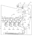
図1は本発明にかかる画像形成装置の第1実施形態であるプリンタの内部構成を示す図、図2は図1の要部拡大図、図3は同プリンタの電気的構成を示すブロック図である。この画像形成装置は、いわゆるタンデム方式のカラープリンタであり、イエロー(Y)、マゼンタ(M)、シアン(C)、ブラック(K)の4色の感光体11Y、11M、11C、11Kを装置本体2内に並設している。このプリンタは、湿式現像方式を採用して、各感光体11Y、11M、11C、11K上のトナー像を重ね合わせてフルカラー画像を形成したり、ブラック(K)のトナー像のみを用いてモノクロ画像を形成するものである。このプリンタでは、ホストコンピュータなどの外部装置から画像信号を含む印刷命令が主制御部100に与えられると、この主制御部100からの制御信号に応じてエンジン制御部110がエンジン部1の各部を制御して、装置本体2の下部に配設された給紙カセット3から搬送した転写紙、複写紙およびOHP用紙などの記録媒体4に上記画像信号に対応する画像を印字出力する。
<First Embodiment>
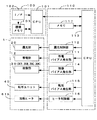
FIG. 1 is a diagram showing an internal configuration of a printer that is a first embodiment of an image forming apparatus according to the present invention, FIG. 2 is an enlarged view of a main part of FIG. 1, and FIG. 3 is a block diagram showing an electrical configuration of the printer. is there. This image forming apparatus is a so-called tandem type color printer, and the four color photoconductors 11Y, 11M, 11C, and 11K of yellow (Y), magenta (M), cyan (C), and black (K) are provided in the apparatus main body. 2 in parallel. This printer employs a wet development system to form a full-color image by superimposing the toner images on the photoconductors 11Y, 11M, 11C, and 11K, or a monochrome image using only a black (K) toner image. Is formed. In this printer, when a print command including an image signal is given to the main control unit 100 from an external device such as a host computer, the
上記エンジン部1では、転写ユニット40の一構成要素である中間転写ベルト41の周回方向47に沿って並設された4つの感光体11Y、11M、11C、11Kのそれぞれに対応して、帯電部12、露光部20、現像部30(30Y、30M、30C、30K)および感光体クリーニング部14が設けられている。また、各現像部30Y、30M、30C、30Kは、各色トナーを分散した現像液32を貯留するタンク33(33Y、33M、33C、33K)をそれぞれ備えている。なお、これら帯電部12、露光部20、現像部30および感光体クリーニング部14の構成はいずれのトナー色についても同一である。したがって、ここでは、イエローに関する構成について説明し、その他のトナー色については同一または相当符号を付して説明を省略する。
In the
図2に示すように、感光体11Yは矢印の方向(図中、時計回り方向)に回転自在に設けられており、その直径は約40mmである。そして、この感光体11Yの周りには、その回転方向に沿って、帯電部12、現像ローラ31、除電部(図示省略)および感光体クリーニング部14が配設されている。また、帯電部12と現像位置16との間の表面領域が露光部20からの光ビーム21の照射領域となっている。帯電部12は、帯電バイアス発生部111から帯電バイアスが印加されて、感光体11Yの外周面を所定の表面電位Vd(例えばVd=DC+600V)に均一に帯電するもので、帯電手段としての機能を有する。
As shown in FIG. 2, the photoreceptor 11Y is rotatably provided in the direction of the arrow (clockwise direction in the figure), and its diameter is about 40 mm. A charging unit 12, a developing roller 31, a charge eliminating unit (not shown), and a
この帯電部12によって均一に帯電された感光体11Yの外周面に向けて露光部20から例えばレーザで形成される光ビーム21が照射される。この露光部20は、露光制御部112から与えられる制御指令に応じて光ビーム21により感光体11Yを露光して、感光体11Y上に画像信号に対応するイエロー用静電潜像を形成するもので、露光手段としての機能を有する。例えば、ホストコンピュータなどの外部装置よりインターフェース102を介して主制御部100のCPU101に画像信号を含む印刷命令が与えられると、主制御部100のCPU101からの指令に応じてCPU113が露光制御部112に対し所定のタイミングで画像信号に対応した制御信号を出力する。そして、この露光制御部112からの制御指令に応じて露光部20から光ビーム21が感光体11Yに照射されて、画像信号に対応するイエロー用静電潜像が感光体11Y上に形成される(潜像形成処理)。また、必要に応じてパッチ画像を形成する場合には、予め設定された所定パターン(例えば、べた画像、細線画像、白抜き細線画像、レジストマークなど)の画像信号に対応した制御信号がCPU113から露光制御部112に与えられ、該パターンに対応するイエロー用静電潜像が感光体11Y上に形成される。
A
こうして形成されたイエロー用静電潜像は現像部30Yの現像ローラ31から供給されるイエロートナーによって顕像化される(現像処理)。そして、感光体11Y上に形成されたイエロートナー像は、感光体11Yの回転に伴って1次転写ローラ53Yと対向する1次転写位置42Yに搬送される。この1次転写ローラ53Yは感光体11Yとで中間転写ベルト41を挟み込むように配置されている。また、この中間転写ベルト41は複数のローラ43a〜43e,44,45に掛け渡されており、図示を省略する駆動モータにより感光体11Yに従動する方向(図1中、反時計回り)47に感光体11Yと等しい周速で周回走行する。そして、転写バイアス発生部115から1次転写バイアス(例えばDC−400V)が印加されると、感光体11Y上のイエロートナー像が1次転写位置42Yで中間転写ベルト41に1次転写される(転写処理)。 The yellow electrostatic latent image formed in this way is visualized by the yellow toner supplied from the developing roller 31 of the developing unit 30Y (developing process). The yellow toner image formed on the photoreceptor 11Y is conveyed to the primary transfer position 42Y that faces the primary transfer roller 53Y as the photoreceptor 11Y rotates. The primary transfer roller 53Y is disposed so as to sandwich the intermediate transfer belt 41 with the photoreceptor 11Y. The intermediate transfer belt 41 is stretched around a plurality of rollers 43a to 43e, 44, 45, and is moved in a direction 47 (counterclockwise in FIG. 1) that is driven by the photoconductor 11Y by a drive motor (not shown). It runs around at a peripheral speed equal to that of the photoreceptor 11Y. When a primary transfer bias (for example, DC-400 V) is applied from the transfer bias generator 115, the yellow toner image on the photoreceptor 11Y is primarily transferred to the intermediate transfer belt 41 at the primary transfer position 42Y ( Transcription process).
一方、1次転写後における感光体11Y上の残留電荷はLEDなどからなる除電部により除去され、残留現像液は感光体クリーニング部14により除去される。この感光体クリーニング部14は、感光体11Yの表面に当接されたゴム製の感光体クリーニングブレード141を有し、中間転写ベルト41にトナー像が1次転写された後に、感光体11Y上に残存する現像液32を感光体クリーニングブレード141により掻き落として除去することができる。なお、この現像部30Yの構成および動作については後で詳述する。
On the other hand, the residual charge on the photoconductor 11Y after the primary transfer is removed by a charge eliminating unit such as an LED, and the residual developer is removed by the photoconductor cleaning unit. The
また、他のトナー色についても、イエロー(Y)と同様に構成されており、画像信号に対応したトナー像が形成される。そして、感光体11Y、11M、11C、11K上に形成されたイエロー(Y)、マゼンタ(M)、シアン(C)、ブラック(K)の各色トナー像は、1次転写ローラ53Y、53M、53C、53Kと対向する1次転写位置42Y、42M、42C、42Kでそれぞれ1次転写されることにより、中間転写ベルト41の表面上で重ね合わされてフルカラーのトナー像が形成される。
The other toner colors are configured in the same manner as yellow (Y), and a toner image corresponding to the image signal is formed. The yellow (Y), magenta (M), cyan (C), and black (K) toner images formed on the photoconductors 11Y, 11M, 11C, and 11K are
中間転写ベルト41に形成されたトナー像は中間転写ベルト41の回転に伴ってローラ45、48で挟まれた2次転写位置49に搬送される。一方、給紙カセット3(図1)に収容されている記録媒体4は、1次転写トナー像の搬送に同期して後述する搬送ユニット70により2次転写位置49に搬送される。そして、ローラ48は中間転写ベルト41に従動する方向(図1中、時計回り)に中間転写ベルト41と等しい周速で回転しており、転写バイアス発生部115から2次転写バイアスが印加されると、中間転写ベルト41上のトナー像が記録媒体4に2次転写される。このローラ48としては、例えば、ゴム硬度がJIS−Aで約50度のウレタンゴムで構成されており、その直径が約25mmのものを用いることができる。なお、この実施形態ではローラ転写を採用しているため、定電圧制御により転写条件を設定したり、定電流制御により転写条件を設定することができる。また、ローラ転写の代わりに、コロナ放電により転写を行うようにしてもよいが、この場合にはコロナ放電の出力を制御することで転写条件を設定することができる。2次転写後における中間転写ベルト41上の残留現像液はクリーニングブレード51により除去される。
The toner image formed on the intermediate transfer belt 41 is conveyed to a
上記のようにしてトナー像が2次転写された記録媒体4は、所定の搬送経路5(図1中、一点鎖線)に沿って搬送され、定着ユニット60によってトナー像が記録媒体4に定着され、装置本体2の上部に設けられた排出トレイに排出される。この定着ユニット60は加熱ヒータ61hを内蔵する加熱ローラ61と、加熱ローラ61に接触する加圧ローラ62とを備えている。そして、ヒータ制御部116により加熱ヒータ61hの作動を制御することで定着ユニット60での定着温度が任意の温度に調整可能となっている。
The
また、この実施形態にかかる画像形成装置では、記録媒体4を所定の搬送経路5に沿って搬送するための搬送ユニット70が設けられている。この搬送ユニット70では、図1に示すように、給紙カセット3に対応して給紙ローラ71が設けられており、この給紙ローラ71により給紙カセット3に収容されている記録媒体4を1枚ずつ取出し、フィードローラ72に搬送する。そして、このフィードローラ72が記録媒体4をゲートローラ73に搬送し、このゲートローラ位置で一時的に待機させる。そして、上記のように2次転写動作に対応したタイミングでゲートローラ73が駆動して記録媒体4を2次転写位置49に送り込む。また、排出トレイ側では、排出前ローラ74、排出ローラ75および反転コロ76が設けられており、2次転写された記録媒体4は定着ユニット60、排出前ローラ74および排出ローラ75を経由して排出トレイ側に搬送される。
In the image forming apparatus according to this embodiment, a
ここで、両面印刷するためには記録媒体4を反転させて再度ゲートローラ73に搬送する必要があるため、排出ローラ75は正逆回転可能となっている。すなわち、記録媒体4をそのまま排出トレイに排出する際には、正回転し続けて記録媒体4を排出トレイに完全に搬送する。一方、反転再給送する際には、記録媒体4の後端部が排出前ローラ74と排出ローラ75との間の所定位置に達すると、排出ローラ75が逆回転して記録媒体4を反転コロ76に送り込む。これによって記録媒体4は反転経路5aに沿って再給送中間ローラ77に搬送される。そして、再給送中間ローラ77および再給送ゲート前ローラ78がゲートローラ73に記録媒体4を搬送し、このゲートローラ位置で一時的に待機させる。こうして、記録媒体4の反転再給送が行われる。このとき、2次転写位置49において中間転写ベルト41と当接し画像を転写される記録媒体4の面は、先に画像が転写された面とは反対の面である。このようにして、記録媒体4の両面に画像を形成することができる。また、該反対の面に2次転写が実行される際、先に画像が転写された面がローラ48に接触するが、この際、完全に記録媒体4に定着されていないトナーがローラ48に付着することがある。このようにしてローラ48に付着したトナーは、クリーニングブレード52により除去される。
Here, in order to perform double-sided printing, it is necessary to reverse the
なお、図3において、主制御部100は、インターフェース102を介して外部装置から与えられた画像信号を記憶するための画像メモリ103を備えており、CPU101は、外部装置から画像信号を含む印刷命令をインターフェース102を介して受信すると、エンジン部1の動作指示に適した形式のジョブデータに変換し、エンジン制御部110に送出する。
In FIG. 3, the main control unit 100 includes an image memory 103 for storing an image signal given from an external device via the
また、エンジン制御部110のメモリ117は、予め設定された固定データを含むCPU113の制御プログラムを記憶するROMや、エンジン部1の制御データやCPU113による演算結果などを一時的に記憶するRAMなどからなる。CPU113はCPU101を介して外部装置から送られた画像信号に関するデータをメモリ117に格納する。
The memory 117 of the
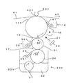
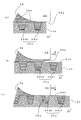
続いて、現像部30Yの構成および動作について図2、図4および図5を参照しつつ詳述する。図4は表面に溝が形成されたアニロクスローラの斜視概念図、図5は塗布ローラおよび規制ブレードの拡大模式図である。なお、現像部30M,30C,30Kの構成は現像部30Yの構成と同様であり、同一構成には同一符号または相当符号を付して説明を省略する。現像部30Y,30M,30C,30Kは本発明の「現像装置」として機能している。
Next, the configuration and operation of the developing unit 30Y will be described in detail with reference to FIGS. 4 is a perspective conceptual view of an anilox roller having grooves formed on the surface, and FIG. 5 is an enlarged schematic view of an application roller and a regulating blade. The configurations of the developing
この現像部30Yは、現像ローラ31(本発明の「現像剤担持体」に相当)に加えて、イエロートナーを分散した現像液32を貯留するタンク33Yと、該タンク33Yに貯留された現像液32を撹拌する撹拌ローラ37と、該現像液32を汲み出して現像ローラ31に塗布する塗布ローラ34と、該塗布ローラ34上の現像液層の厚さを均一に規制する規制ブレード35と、感光体11Yへのトナー供給後に現像ローラ31上に残留した現像液を除去する現像ローラクリーニング部36とを備えている。現像ローラ31は感光体11Yに従動する方向D1(図2中、反時計回り)に感光体11Yとほぼ等しい周速で回転する。また、塗布ローラ34は現像ローラ31に従動する方向D2(図2中、時計回り)に現像ローラ31とほぼ等しい周速で回転する。
The developing unit 30Y includes, in addition to the developing roller 31 (corresponding to the “developer carrier” of the present invention), a tank 33Y that stores a
現像液32(本発明の「液体現像剤」に相当)は、本実施形態では、平均粒径0.1〜5μm程度の着色顔料、この着色顔料を接着するエポキシ樹脂などの接着剤、トナーに所定の電荷を与える荷電制御剤、着色顔料を均一に分散させる分散剤等からなるトナーが、液体キャリア中に分散されてなる。本実施形態では、液体キャリアとして、例えばポリジメチルシロキサンオイルなどのシリコーンオイルを用いており、トナー濃度を5〜40重量%として、湿式現像方式で多く用いられる低濃度現像液(トナー濃度が1〜2重量%)に比べて高濃度にしている。なお、液体キャリアの種類はシリコーンオイルに限定されるものではなく、例えば、エクソン化学製のアイソパーL(商品名)やパラフィンオイルを用いることができる。また、現像液32の粘度は、使用する液体キャリアやトナーを構成する各材料、トナー濃度などによって決まるが、本実施形態では、例えば粘度を100〜10000mPa・sとしている。
In this embodiment, the developer 32 (corresponding to the “liquid developer” of the present invention) is applied to a color pigment having an average particle size of about 0.1 to 5 μm, an adhesive such as an epoxy resin to which the color pigment is adhered, and a toner. A toner composed of a charge control agent that gives a predetermined charge, a dispersant that uniformly disperses the color pigment, and the like is dispersed in a liquid carrier. In this embodiment, for example, a silicone oil such as polydimethylsiloxane oil is used as the liquid carrier, and the toner concentration is 5 to 40% by weight. 2% by weight). In addition, the kind of liquid carrier is not limited to silicone oil, For example, Isopar L (trade name) manufactured by Exxon Chemical or paraffin oil can be used. The viscosity of the
感光体11Yと現像ローラ31との間隔(現像ギャップ=現像液層の厚さ)は、本実施形態では例えば5〜40μmに設定し、現像ニップ距離(現像液層が感光体11Yおよび現像ローラ31の双方に接触している周方向の距離)は、本実施形態では例えば5mmに設定している。上述した低濃度現像液の場合にはトナー量を稼ぐべく100〜200μmの現像ギャップを必要とするのに比べて、高濃度現像液を用いる本実施形態では現像ギャップを短縮することができる。従って、現像液中を電気泳動によって移動するトナーの移動距離が短縮するとともに、同一の現像バイアスを印加してもより高い電界が発生するので、現像効率を向上することができ、現像を高速に行えることとなる。 In this embodiment, the distance between the photoconductor 11Y and the developing roller 31 (development gap = thickness of the developer layer) is set to, for example, 5 to 40 μm, and the development nip distance (the developer layer is the photoconductor 11Y and the developing roller 31). In this embodiment, the distance in the circumferential direction in contact with both is set to 5 mm, for example. In the case of the low-concentration developer described above, a development gap of 100 to 200 μm is required to increase the amount of toner, and in this embodiment using a high-concentration developer, the development gap can be shortened. Accordingly, the moving distance of the toner moving in the developer by electrophoresis is shortened, and a higher electric field is generated even when the same developing bias is applied, so that the developing efficiency can be improved and the developing can be performed at a high speed. It will be possible.
撹拌ローラ37は、タンク33Yに収容されている現像液32を汲み上げて塗布ローラ34へ搬送する。この撹拌ローラ37は、その下部がタンク33Yに貯留された現像液32に浸されており、また、塗布ローラ34から、約1mmの幅を持って離間している。さらに、撹拌ローラ37は、その中心軸を中心として回転可能であり、該中心軸は、塗布ローラ34の回転中心軸よりも下方にある。また、撹拌ローラ37は、塗布ローラ34の回転方向(図2中、時計回り)と同じ方向に回転する。なお、撹拌ローラ37は、タンク33Yに収容された現像液32を汲み上げて塗布ローラ34へ搬送する機能を有するとともに、現像液32を適正な状態に維持するためにを撹拌する機能をも有している。このような撹拌ローラとしては、例えば、鉄等金属性のローラであり、その直径が約20mmのものを用いることができる。
The agitating
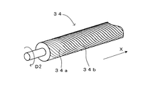
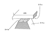
塗布ローラ34は、タンク33Yから撹拌ローラ37により搬送された現像液32を塗布位置17において現像ローラ31へ供給する。この塗布ローラ34は、鉄等金属性のローラの表面に図4に示すように溝34a(本発明の「凹部」に相当)が均一かつ螺旋状に形成されニッケルメッキが施された、いわゆるアニロクスローラを呼称されるものであり、その直径は約25mmである。本実施形態では、図4に示すように、塗布ローラ34の回転方向D2に対して斜めに複数の溝34aが形成されている。
The
この塗布ローラ34は時計回りに回転しながら現像液32に接触することによって、溝34aに現像液32を担持して、該担持した現像液32を現像ローラ31へ搬送する。したがって、塗布ローラ34は溝34aが形成されているX方向の幅で現像ローラ31に現像液32を塗布することができる。なお、溝ピッチ(スラスト方向(X方向)において、溝34aを形成する山と山の周期)は、必要な現像液32の膜厚に応じておよそ55〜250μmとするのが好ましい。本実施形態では、溝ピッチが約170μm、山の幅が約45μm、溝34aの幅30μm、溝34aの深さが約50μmとなるように構成されている。また、塗布ローラ34の表面の、溝34a間の山34bが本発明における「凸部」に相当している。また、本実施形態では、山34b部の表面粗さRaをR1a≒0.03μm、溝34a部の表面粗さRaをR2a≒0.15μmとなるように構成している。
The
また、塗布ローラ34は、該塗布ローラ34上の現像液32を現像ローラ31に適切に塗布するために、その表面が、該現像ローラ31の後述する弾性体の層に圧接している。また、塗布ローラ34は、その中心軸を中心として回転可能であり、当該中心軸は、現像ローラ31の回転中心軸よりも下方にある。また、塗布ローラ34は、現像ローラ31の回転方向(図2中、反時計回り)と逆の方向(図2中、時計回り)に回転する。
Further, the surface of the
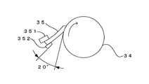
規制ブレード35(本発明の「規制部材」に相当)は、塗布ローラ34の回転方向D2における塗布位置17の上流側において、その腹部で塗布ローラ34の表面に接触して、塗布ローラ34上の現像液32の量を規制する。すなわち、規制ブレード35は、塗布ローラ34表面の山34b部分の余剰な現像液32を掻き取って、現像ローラ31に供給する塗布ローラ34の現像液32の量を計量する役割を果たしている。この規制ブレード35は、弾性体としてのウレタンゴムからなり、厚さ約1.6mmのブレード状のウレタンゴムが鉄等金属製の規制ブレード支持部材351によって支持されている。なお、規制ブレード35のゴム硬度は、JIS−Aで約77度であり、規制ブレード35の、塗布ローラ34表面への当接部の硬度(約77度)は、後述する現像ローラ31の弾性体の層の、塗布ローラ34表面への圧接部、の硬度(約85度)よりも低くなっている。また、本実施形態において、規制ブレード35は、その先端が塗布ローラ34の回転方向の下流側に向くように配置されており、いわゆるトレール規制を行っている。図5に示すように、規制ブレード35と塗布ローラ34との接触位置における、塗布ローラ34の外周面の接線と規制ブレード35の腹部とのなす角を接触角としたとき、本実施形態では、該接触角が15°となるように規制ブレード35を支持部材351によって支持している。また、本実施形態では、規制ブレード35の塗布ローラ34に接触する部分の表面粗さRaがR3a≒0.06μmとなるように構成されている。なお、規制ブレード35と塗布ローラ34の接触部の状態等については後で詳細に述べる。
The regulating blade 35 (corresponding to the “regulating member” of the present invention) is in contact with the surface of the
現像ローラ31は、感光体11Yに担持された静電潜像を現像液32により現像するために、現像液32を担持して感光体11Yと対向する現像位置16に搬送する。この現像ローラ31は、鉄等金属製の内芯の外周部に、導電性を有する弾性部の一例としての弾性体の層を備えたものであり、その直径は約20mmである。また、弾性体の層は、二層構造になっており、その内層として、ゴム硬度がJIS−A約30度で、厚み約5mmのウレタンゴムが、その表層(外層)として、ゴム硬度がJIS−A約85度で、厚み約30μmのウレタンゴムが備えられている。そして、現像ローラ31は、その表層が圧接部となって、弾性変形された状態で塗布ローラ34及び感光体11Yのそれぞれに圧接して
いる。なお、現像ローラ31の表面の表面粗さRaはR4a≒0.4μmとなるように構成されている。
The developing roller 31 carries the
また、現像ローラ31は、その中心軸を中心として回転可能であり、該中心軸は、感光体11Yの回転中心軸よりも下方にあって、感光体11Yの回転方向と逆の方向D1(図2中、反時計回り)に回転する。なお、感光体11Y上に形成された静電潜像を現像する際には、現像ローラ31と感光体11Yとの間に電界が形成される。 Further, the developing roller 31 is rotatable about its central axis, and the central axis is below the rotational central axis of the photoconductor 11Y and is in a direction D1 opposite to the rotation direction of the photoconductor 11Y (FIG. 2 counterclockwise). When developing the electrostatic latent image formed on the photoconductor 11Y, an electric field is formed between the developing roller 31 and the photoconductor 11Y.
現像ローラクリーニング部36は、現像ローラ31の回転方向D1における現像位置16の下流側において、現像ローラ31のスラスト方向に沿って、該現像ローラ31の表面に当接されたゴム製の現像ローラクリーニングブレード361を有する。そして、前記現像位置16で現像が行われた後に、現像ローラ31上に残存する現像液32を現像ローラクリーニングブレード361により掻き落として除去するための装置である。
The developing roller cleaning unit 36 cleans a developing roller made of rubber that is in contact with the surface of the developing roller 31 along the thrust direction of the developing roller 31 on the downstream side of the developing position 16 in the rotation direction D1 of the developing roller 31. It has a blade 361. Then, after developing at the developing position 16, the developing
なお、本実施形態では、塗布ローラ34から現像ローラ31へ良好に現像液32が移動するように、塗布ローラ34の回転軸と現像ローラ31の回転軸との軸間距離が、塗布ローラ34の半径と現像ローラ31の半径との和よりも小さくなるように構成している。上記したように、塗布ローラ34の直径を約25mm、現像ローラ31の直径を約20mmとした場合、塗布ローラ34の回転軸と現像ローラ31の回転軸との軸距離を、例えば、約22.3mmとすることができる。
In the present embodiment, the distance between the rotation axis of the
このように構成された現像部30Yにおいて、撹拌ローラ37が、その中心軸回りに回転することによって、タンク33Yに収容されている現像液32を汲み上げて塗布ローラ34へ搬送する。塗布ローラ34に搬送された現像液32は、塗布ローラ34の回転によって、規制ブレード35の当接位置に至る。そして、該当接位置を通過する際に、現像液32の余剰分が規制ブレード35によって掻き取られ、現像ローラ31に供給される現像液32の量が計量される。すなわち、塗布ローラ34には、前述したとおり、溝34aが設けられているから、塗布ローラ34に当接する規制ブレード35は、溝34aに担持された現像液32を残して、塗布ローラ34から現像液32を掻き取ることとなる。また、現像ローラ31に供給される現像液32の量が適正な量になるように溝34aの寸法が決められているので、規制ブレード35が塗布ローラ34上の現像液32を掻き取った際には、溝34aによって適正な量に計量された現像液32が溝34aに残存することとなる。
In the developing
このようにして、タンク33Yに貯留された現像液32が塗布ローラ34により汲み出され、規制ブレード35により塗布ローラ34上の現像液32の量が均一に規制され、この均一な現像液32が塗布位置17において現像ローラ31の表面に塗布され、現像ローラ31の回転に伴って感光体11Yに対向する現像位置16に搬送される。現像液32中のトナーは、荷電制御剤などの作用によって例えば正に帯電している。そして、現像位置16において現像ローラ31に担持されている現像液32が、現像ローラ31から供給されて感光体11Yに付着し、現像バイアス発生部114から現像ローラ31に印加される現像バイアスVb(例えばVb=DC+400V)によってイエロートナーが現像ローラ31から感光体11Yに移動して、イエロー用静電潜像が顕像化される。また、感光体11Yに付着せずに現像ローラ31上に残った現像液は、現像ローラクリーニングブレード361により掻き落とされる。
In this manner, the
このようにして、感光体11Y上に形成されたイエロートナー像は、上述したように、1次転写位置42Yにおいて中間転写ベルト41に1次転写され、1次転写が終了後に感光体11Yに残留している現像液32は感光体クリーニング部14によって除去される。
As described above, the yellow toner image formed on the photoreceptor 11Y in this way is primarily transferred to the intermediate transfer belt 41 at the primary transfer position 42Y, and remains on the photoreceptor 11Y after the primary transfer is completed. The developing
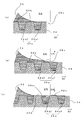
続いて、上記「発明が解決しようとする課題」の項で説明した課題について、図6ないし図8を参照しつつ詳述する。図6は塗布ローラおよび規制ブレードの部分拡大図、図7は液体現像剤が規制される様子を表す模式図、図8は塗布ローラから現像ローラへ液体現像剤が塗布される様子を表す模式図である。上記したように、本発明者らは、塗布ローラ34と規制ブレード35との接触部において、規制ブレード35が微振動してしまうことが、現像ローラ31に塗布される現像液32の塗布パターンに乱れを生じさせる一因であることを見いだした。このような規制ブレード35の微振動は、塗布ローラ34表面に形成されているの溝34aと山34b、塗布ローラ34表面の山34b部の表面粗さ、および規制ブレード35の塗布ローラ34との接触部分である腹部35aの表面粗さ等に起因して発生すると考えられる(図6参照)。
Subsequently, the problem described in the above section “Problems to be Solved by the Invention” will be described in detail with reference to FIGS. FIG. 6 is a partially enlarged view of the application roller and the regulation blade, FIG. 7 is a schematic diagram showing how the liquid developer is regulated, and FIG. 8 is a schematic diagram showing how the liquid developer is applied from the application roller to the development roller. It is. As described above, the present inventors have found that the fine vibration of the
続いて、上記したような微振動が発生している場合に、塗布ローラ34上の現像液32が規制ブレード35によって規制される様子について図7を参照しつつ詳述する。図7(a)は塗布ローラ34の表面に規制ブレード35の腹部35aが接触している様子を示している。塗布ローラ34の回転動作にともない、塗布ローラ34の表面が矢印D2の方向へ進んでいくことによって、塗布ローラ34上の余分な現像液32が規制ブレード35の腹部35aによって掻き取られることとなる。
Next, the manner in which the
図7(b)は規制ブレード35による塗布ローラ34上の現像液32の規制動作(掻き取り動作)中に、規制ブレード35に微振動が生じた際の様子を示している。この微振動により、規制ブレード35は矢印UPの方向へ微小時間移動した状態となり、該微小時間の間、規制ブレード35の腹部35aが塗布ローラ34の表面から離間した状態となる。この際、図7(b)に示すように、溝34a1と溝34a2との間の山34bに担持されている現像液32を、該腹部35aは掻き取ることができない状態となる。
FIG. 7B shows a state in which a slight vibration is generated in the
図7(c)は図7(b)の状態から、規制ブレード35が矢印DWの方向へ移動して、規制ブレード35の腹部35aが再び塗布ローラ34の表面に接触した様子を示している。上記したように、規制ブレード35に発生した微振動によって、規制ブレード35の腹部35aが塗布ローラ34の表面から離間した状態となってしまった際、該腹部35aによって塗布ローラ34上の現像液32の余剰分を掻き取ることができなくなる。このように、塗布ローラ34表面の山34bの現像液32を規制ブレード35で完全に規制する(掻き取る)ことができないため、該山34bには現像液32aが担持されたままとなってしまう。
FIG. 7C shows a state in which the
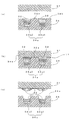
続いて、上記したように、塗布ローラ34上の現像液32の余剰分を完全に規制することができなかった状態で、該塗布ローラ34上の現像液32が現像ローラ31に塗布される様子について図8を参照しつつ詳述する。図8(a)は、塗布ローラ34の溝34a(34a1,34a2)に現像液32が、山34bに余剰分の現像液32aが担持されている様子を示す。図8(a)に示すように、塗布ローラ34は現像液32を溝34aに、余剰分の現像液32aを山34bに担持して、該現像液32を塗布位置17へ搬送する。
Subsequently, as described above, the developing
図8(b)は、塗布位置17において、現像ローラ31と塗布ローラ34とが圧接している様子を示す。現像ローラ31は、塗布位置17において、塗布ローラ34と圧接することによって、表面のゴム層が弾性変形して溝34aに食い込んで、該溝34aに担持されている現像液32に接触する。
FIG. 8B shows a state where the developing roller 31 and the
その後、塗布ローラ34および現像ローラの回転移動にともない、塗布ローラ34の表面と現像ローラ31とが圧接した状態から、離間した状態となる(図5(c))。このとき、図8(c)に示すように、溝34a(34a1,34a2)に担持されていた現像液32と一緒に、規制ブレード35によって規制することができなかった山34bに担持されていた現像液32aが現像ローラ31に移動することによって、現像ローラ31に塗布されてしまう。この結果、塗布ローラ34表面の溝34a部に担持された現像液32を現像ローラ31に塗布する際、山34bに担持されていた現像液32aがいわゆる「リブ」の原因となり、現像ローラ31に塗布された現像液32の塗布パターンに乱れが生じてしまう。
Thereafter, with the rotational movement of the
一方、本発明にかかる第1実施形態においては、上記したように、塗布ローラ34表面の山34b部の表面粗さをR1a、溝34a部の表面粗さをR2a、規制ブレード35の腹部35aの表面粗さをR3aとしたとき、
第1条件:R1a<R3a<R2a
を満足するように構成されている。このように構成することで、塗布ローラ34が規制ブレード35との接触部を通過した後、上記したような余剰な現像液32aが塗布ローラ34表面の山34b部に残留することを防止することができる。この本発明の基本原理について図9を参照しつつ詳述する。
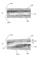
On the other hand, in the first embodiment according to the present invention, as described above, the surface roughness of the crest 34b of the
First condition: R1a <R3a <R2a
It is configured to satisfy. With this configuration, after the
図9は本発明の基本原理を示す模式図である。図9(a)は、上板UBと下板SBとで現像液32を挟んだ状態を示している。上板UBの現像液32と接触する側の面UBaの表面粗さRaをRub、下板SBの現像液32と接触する側の面SBaの表面粗さRaをRsbとしたとき、
Rub<Rsb
を満足するように構成されている。
FIG. 9 is a schematic diagram showing the basic principle of the present invention. FIG. 9A shows a state in which the
Rub <Rsb
It is configured to satisfy.
続いて、図9(b)に示すように、上板UBと下板SBとを離間する方向へ移動させた場合、表面粗さRaの大きい下板SB側により多くの現像液32が付着する。すなわち、上板UBの面UBaの表面粗さRaと、下板SBの面SBaの表面粗さRaとの関係が上記関係を満足するように構成されているため、上板UBと下板SBを離間させる方向へ移動させた場合、上板UBには厚さHubの現像液32が付着し、下板SBには厚さHsb(>Hub)の現像液32が付着するように、上板UBおよび下板SBに挟まれた現像液32は分離する。
Subsequently, as shown in FIG. 9B, when the upper plate UB and the lower plate SB are moved away from each other,
したがって、本実施形態では、上記第1条件を満足しているため、規制ブレード35によって塗布ローラ34上の現像液32を規制する際、図10を参照しつつ詳述するように、余剰な現像液32aが塗布ローラ34表面の山34bに残留することを防止することができる。図10は液体現像剤が規制される様子を表す模式図である。
Therefore, in the present embodiment, since the first condition is satisfied, when the
図10(a)は塗布ローラ34の表面に規制ブレード35の腹部35aが接触している様子を示している。塗布ローラ34の回転動作にともない、塗布ローラ34の表面が矢印D2の方向へ進んでいくことによって、塗布ローラ34上の余分な現像液32が規制ブレード35の腹部35aによって掻き取られることとなる。
FIG. 10A shows a state where the abdomen 35 a of the
図10(b)は規制ブレード35による塗布ローラ34上の現像液32の規制動作(掻き取り動作)中に、規制ブレード35に微振動が生じた際の様子を示している。この微振動により、規制ブレード35は矢印UPの方向へ微小時間移動した状態となり、該微小時間の間、規制ブレード35の腹部35aが塗布ローラ34の表面から離間した状態となる。この際、山34bの表面粗さR1aは腹部35aの表面粗さR3aよりも小さくなるように構成されているため、図9を参照しつつ詳述した本発明の基本原理により、溝34a1と溝34a2との間の山34bに担持されている現像液32の大部分は、規制ブレード35の腹部35a側に移動する(図10(b)参照)。一方、溝34aの表面粗さR2aは腹部35aの表面粗さR3aよりも大きくなるように構成されているため、規制ブレード35の腹部35aが塗布ローラ34の表面から離間したとしても、溝34aに担持されている現像液32の大部分は該腹部35a側に移動することはない。
FIG. 10B shows a state in which a slight vibration is generated in the
図10(c)は図10(b)の状態から、規制ブレード35が矢印DWの方向へ移動して、規制ブレード35の腹部35aが再び塗布ローラ34の表面に接触した様子を示している。上記したように、規制ブレード35に発生した微振動によって、規制ブレード35の腹部35aが塗布ローラ34の表面から離間した状態となってしまった際、該腹部35aと対向する山34bが担持する現像液32は、腹部35a側へ大部分が移動する。この結果、該腹部35aによって塗布ローラ34上の現像液32の余剰分を確実に掻き取ることができる。このように、塗布ローラ34表面の山34b部の現像液32を規制ブレード35で完全に規制する(掻き取る)ことができるため、塗布ローラ34は溝34a部にのみ現像液32aを担持した状態となる。
FIG. 10C shows a state in which the
以上のように、この実施形態では、塗布ローラ34表面の山34bの表面粗さをR1a、溝34aの表面粗さをR2a、規制ブレード35の腹部35aの表面粗さをR3aとしたとき、
第1条件:R1a<R3a<R2a
を満足するように構成されている。したがって、R1a<R3aを満足しているため、上記した微振動が規制ブレード35に生じたとしても、塗布ローラ34表面の山34bに担持された現像液32は、表面粗さが大きい規制ブレード35の腹部35a側へ移動するため、該規制ブレード35によって確実に掻き取られる。また、R3a<R2aを満足しているため、塗布ローラ34表面の溝34aに担持された現像液32は、塗布ローラ34と規制ブレード35の腹部35aとが接触する部分を通過する際に、表面粗さの小さい規制ブレード35の腹部35a側に移動せず、表面粗さの大きい溝34a部側に確実に担持されたままとなる。
As described above, in this embodiment, when the surface roughness of the crest 34b on the surface of the
First condition: R1a <R3a <R2a
It is configured to satisfy. Therefore, since R1a <R3a is satisfied, even if the above-described fine vibration occurs in the
また、規制ブレード35の微振動の発生に特に影響を与えていると考えられる塗布ローラ34表面の山34b部の表面粗さR1aが最小となるように構成されているため、規制ブレード35に微振動が生じるのが抑制される。このように、塗布ローラ34上の現像液32の余剰分の掻き取りを阻害する規制ブレード35の微振動を抑制することができるので、より確実に塗布ローラ34が担持する現像液32の量を規制することができる。この結果、塗布ローラ34が担持する現像液32の量は、塗布位置17において現像ローラ31に塗布される前に規制ブレード35によって確実に規制され、塗布ローラ34はその表面の溝34a部のみで現像液32を担持することとなる。したがって、塗布位置17において、溝34a部で担持された現像液32のみが現像ローラ31へ塗布されるため、現像ローラ31に塗布される現像液32の塗布パターンのに乱れが生じるのを防止することができる。その結果、塗布パターンに乱れが生じるのを防止された現像ローラ31上の現像液32で感光体上の静電潜像を現像することができるので、良好な画質のトナー像を形成することができる。
Further, since the surface roughness R1a of the crest 34b portion of the surface of the
また、この実施形態では、規制ブレード35の腹部35a(面)で塗布ローラ34を押圧しているので、該押圧力を塗布ローラ34の広範囲に効率良く伝えることができる。したがって、より効率良く、塗布ローラ34表面の山34b部に担持されている現像液32を規制する(掻き取る)ことができる。その結果、確実に山34b部の現像液32が規制された状態で、塗布ローラ34から現像ローラ31へ現像液32を塗布することができるので、現像ローラ31に塗布される現像液32の塗布パターンに乱れが生じるのをさらに効果的に防止することができる。
In this embodiment, since the
また、この実施形態では、アニロクスローラ(塗布ローラ34)の溝34a部で現像液32を担持することによって、一定量に計量した現像液32を現像ローラ31に塗布している。したがって、現像ローラ31に精度よく均一に現像液32を塗布することができる。このように、現像ローラ31に均一に塗布された現像液32によって感光体上の静電潜像を現像することができるので現像精度を向上させ、形成されるトナー像の画質向上を図ることができる。
In this embodiment, the developing
<第2実施形態>
第2実施形態が第1実施形態と大きく相違する点は、規制ブレードを構成する材質が異なる点である。また、塗布ローラの山部、溝部、規制ブレードの腹部および現像ローラの表面粗さRaの値が変更されている。その他の構成は第1実施形態と同様であり、以下、第1実施形態との相違点を中心に第2実施形態について詳細に述べる。なお、第1実施形態と同一な構成および動作については、その構成および動作の説明を省略する。
<Second Embodiment>
The point in which 2nd Embodiment differs greatly from 1st Embodiment is a point from which the material which comprises a control blade differs. Further, the values of the crests and grooves of the application roller, the abdomen of the regulating blade, and the surface roughness Ra of the developing roller are changed. Other configurations are the same as those of the first embodiment, and hereinafter, the second embodiment will be described in detail focusing on differences from the first embodiment. In addition, about the structure and operation | movement same as 1st Embodiment, the description of the structure and operation | movement is abbreviate | omitted.
この第2実施形態における塗布ローラおよび規制ブレードは以下のように構成されている。 The application roller and the regulating blade in the second embodiment are configured as follows.
塗布ローラの山部の表面粗さRa:R1b≒0.01μm
塗布ローラの溝部の表面粗さRa:R2b≒0.1μm
規制ブレードの材質および腹部の表面粗さRa:厚さ約0.5mmのリン青銅;R3b≒0.05μm
規制ブレードと塗布ローラの接触角:約10°
規制方式:トレール規制
現像ローラの表面粗さRa:R4b≒0.4μm
その他の構成および動作は上記第1実施形態と同様である。
Surface roughness Ra of the peak portion of the application roller Ra: R1b≈0.01 μm
Surface roughness Ra of the groove of the coating roller Ra: R2b≈0.1 μm
Regulating blade material and abdominal surface roughness Ra: Phosphor bronze with a thickness of about 0.5 mm; R3b≈0.05 μm
Contact angle between regulating blade and application roller: approx. 10 °
Regulating method: Trail regulation Developing roller surface roughness Ra: R4b≈0.4 μm
Other configurations and operations are the same as those in the first embodiment.
この第2実施形態では、上記第1実施形態と同様に、
第1条件:R1b<R3b<R2b
を満足しているため、上記第1実施形態と同様の作用効果を奏することができる。
In the second embodiment, as in the first embodiment,
First condition: R1b <R3b <R2b
Therefore, the same effects as those of the first embodiment can be achieved.
<第3実施形態>
第3実施形態が上記第1および第2実施形態と大きく相違する点は、規制ブレードを構成する材質が異なる点である。また、塗布ローラの山部、溝部、規制ブレードの腹部および現像ローラの表面粗さRaの値が変更されている。また、この第3実施形態では、後で詳述する第2条件を満足するように構成されている。その他の構成は第1および第2実施形態と同様であり、以下、第1および第2実施形態との相違点を中心に第3実施形態について詳細に述べる。なお、第1および第2実施形態と同一な構成および動作については、その構成および動作の説明を省略する。
<Third Embodiment>
The third embodiment is greatly different from the first and second embodiments in that the material constituting the regulating blade is different. Further, the values of the crests and grooves of the application roller, the abdomen of the regulating blade, and the surface roughness Ra of the developing roller are changed. Further, the third embodiment is configured to satisfy a second condition described in detail later. Other configurations are the same as those of the first and second embodiments, and the third embodiment will be described in detail below, focusing on differences from the first and second embodiments. In addition, about the structure and operation | movement same as 1st and 2nd embodiment, the description of the structure and operation | movement is abbreviate | omitted.
この第3実施形態における塗布ローラおよび規制ブレードは以下のように構成されている。 The application roller and the regulating blade in the third embodiment are configured as follows.
塗布ローラの山部の表面粗さRa:R1c≒0.05μm
塗布ローラの溝部の表面粗さRa:R2c≒0.2μm
規制ブレードの材質および腹部の表面粗さRa:厚さ約0.2mmのステンレス鋼(SUS304);R3c≒0.1μm
規制ブレードと塗布ローラの接触角:約5°
規制方式:トレール規制
現像ローラの表面粗さRa:R4c≒0.15μm
その他の構成および動作は上記第1および第2実施形態と同様である。
Surface roughness Ra of the crest of the coating roller Ra: R1c≈0.05 μm
Surface roughness Ra of the groove portion of the coating roller Ra: R2c≈0.2 μm
The material of the regulating blade and the surface roughness Ra of the abdomen: Stainless steel (SUS304) with a thickness of about 0.2 mm; R3c≈0.1 μm
Contact angle between regulating blade and application roller: approx. 5 °
Regulation method: Trail regulation Development roller surface roughness Ra: R4c≈0.15 μm
Other configurations and operations are the same as those in the first and second embodiments.
この第3実施形態では、上記第1および第2実施形態と同様に、
第1条件:R1c<R3c<R2c
を満足しているため、上記第1および第2実施形態と同様の作用効果を奏することができる。
In the third embodiment, as in the first and second embodiments,
First condition: R1c <R3c <R2c
Therefore, the same effects as those of the first and second embodiments can be achieved.
ところで、塗布ローラ34が時計回りに回転しながら現像液32に接触して溝34aに現像液32を担持する際、溝34aの内部全体に現像液32が充填されずに、特に溝34aの底部に空気を含んでしまうことがある。この溝34aに担持された現像液32に含まれた空気は、塗布ローラ34の回転にともなって塗布位置17へと搬送される過程で、該溝34aに担持された現像液32の表層部分まで移動したりすることがある。その結果、この溝34aに担持された現像液32は現像ローラ31へ上手く転移されず、現像ローラ31に塗布された現像液32の塗布パターンが乱れる原因の一つとなっていた。
By the way, when the
しかしながら、この第3実施形態では、塗布ローラ34の溝34a部の表面粗さR2cと現像ローラ31の表面粗さR4cとの関係が、
第2条件:R2c>R4c
を満足するように構成されている。そのため、図9を参照しつつ詳述した本発明の基本原理により、塗布ローラ34表面の溝34a部に担持された現像液32が現像ローラ31に塗布される際、溝34a部の表面粗さR2cの方が現像ローラ31の表面粗さR4cよりも大きいため、溝34a部に担持された現像液32の全てが現像ローラ31に転移されるわけではなく、その一部は確実に溝34aの底部に残留した状態となる。
However, in the third embodiment, the relationship between the surface roughness R2c of the groove 34a of the
Second condition: R2c> R4c
It is configured to satisfy. Therefore, according to the basic principle of the present invention described in detail with reference to FIG. 9, when the
この結果、再度、塗布ローラ34が時計回りに回転しながら現像液32に接触して溝34aに現像液32を担持する際、溝34aの底部には現像液32が確実に残留しているため、溝34aの底部に空気を含んでしまうことを防止することができる。すなわち、塗布ローラ34表面の溝34aに現像液32を担持する際、該溝34aの内部に空気が含まれるのを効果的に防止することができる。その結果、溝34aの内部全体に充填された現像液32が現像ローラ31へ塗布されるため、現像ローラ31へ塗布された現像液32の塗布パターンが乱れるのをさらに効果的に防止することができる。
As a result, when the
<第4実施形態>
図11は本発明にかかる画像形成装置の第4実施形態の要部拡大図である。この実施形態が上記第1ないし第3実施形態と大きく異なる点は、規制ブレードを支持する支持部材351が調整部材352をさらに有する点である。その他の構成は第1ないし第3実施形態と同様である。以下、第1ないし第3実施形態との相違点を中心に第4実施形態について詳細に述べる。なお、第1ないし第3実施形態と同一な構成および動作については、その構成および動作の説明を省略する。
<Fourth embodiment>
FIG. 11 is an enlarged view of a main part of a fourth embodiment of the image forming apparatus according to the present invention. This embodiment is greatly different from the first to third embodiments in that the support member 351 that supports the regulating blade further includes an adjustment member 352. Other configurations are the same as those in the first to third embodiments. Hereinafter, the fourth embodiment will be described in detail focusing on differences from the first to third embodiments. In addition, about the structure and operation | movement same as 1st thru | or 3rd embodiment, the description of the structure and operation | movement is abbreviate | omitted.
この第4実施形態では、規制ブレード35を支持する支持部材351が調整部材352をさらに有し、規制ブレード35と塗布ローラ34との接触位置における、塗布ローラ34の外周面の接線と規制ブレード35の腹部とがなす角を接触角としたとき、調整部材352を調整することによって、接触角を0°〜45°の範囲で任意に調整可能となっている。本実施形態では、接触角が約20°となるように、調整部材352が調整されている。
In the fourth embodiment, the support member 351 that supports the
このように、接触角を調整することによって、規制ブレード35に任意な大きさで撓りを生じさせ、規制ブレード35の弾性力の大きさを任意に調整することができる。したがって、規制ブレード35が塗布ローラ34を押圧する力を任意に調整することができる。よって、塗布ローラ34の構成や規制ブレード35の構成(弾性力等)に応じて、規制ブレード35によって塗布ローラ34を押圧する力を任意に調整することができる。したがって、規制ブレード35によって塗布ローラ34を押圧する力を、塗布ローラ34および規制ブレード35の構成に応じて任意に調整して、塗布ローラ34表面に担持されている現像液32をより効率よく規制する(掻き取る)ことができる。その結果、現像ローラ31に塗布された現像液32の塗布パターンに乱れが生じるのをさらに効果的に防止することができる。
In this way, by adjusting the contact angle, the
<その他>
なお、本発明は上記実施形態に限定されるものではなく、その趣旨を逸脱しない限りにおいて上述したものに対して種々の変更を加えることが可能である。例えば、上記した表面粗さRaの各数値は、これらの値に限定されるものではなく、製造条件や材質等によって設定すればよい。要は、上記第1条件を満足するように構成すればよい。また、装置構成によっては、第1条件と同時に、第2条件を満足するように構成すれば、より効果的に良好な画質のトナー像を形成することができる。
<Others>
The present invention is not limited to the above-described embodiment, and various modifications can be made to the above-described one without departing from the spirit of the present invention. For example, the numerical values of the surface roughness Ra described above are not limited to these values, and may be set according to manufacturing conditions, materials, and the like. In short, what is necessary is just to comprise so that the said 1st condition may be satisfied. In addition, depending on the configuration of the apparatus, if the second condition is satisfied simultaneously with the first condition, a toner image with good image quality can be formed more effectively.
また、上記第1ないし第4実施形態では、露光部20を各感光体11Y,11M,11C,11Kに1対1に対応して設け、各感光体11Y,11M,11C,11Kのそれぞれに、対応した静電潜像を形成するように構成したが、例えば、1つの露光部を配設し、レーザービームの照射方向をミラー等を用いて切り替えることによって、各感光体11Y,11M,11C,11Kのそれぞれに対応した静電潜像を形成する構成としてもよい。その他、LEDアレイを用いた露光手段を使用したり、いわゆる書込帯電を行う潜像書込み手段を用いても構わない。要は、各感光体11Y,11M,11C,11Kのそれぞれに、1対1に対応した静電潜像を形成できる構成であれば、どのような構成としてもよい。
In the first to fourth embodiments, the
また、上記第1ないし第4実施形態では、規制ブレード35はトレール規制を行っているが、規制ブレードの35の先端が塗布ローラ34の回転方向の上流側に向くように配置して、いわゆるカウンタ規制を行っても構わない。また、本発明における規制部材を規制ローラによって構成することもできる。要は、塗布ローラに接触することによって塗布ローラ上の現像液の量を規制する規制部材に本発明を適用することができる。
In the first to fourth embodiments, the
また、上記第4実施形態における構成を、第1ないし第3実施形態で採用しても構わない。この場合、規制ブレードを構成する各種材料の弾性係数等に応じて、規制ブレードと塗布ローラとの接触角を任意に変更することができるので、より効果的に規制ブレードによって塗布ローラ34上の液体現像剤の量を規制することができる。
Further, the configuration in the fourth embodiment may be adopted in the first to third embodiments. In this case, since the contact angle between the regulating blade and the application roller can be arbitrarily changed according to the elastic coefficient of various materials constituting the regulating blade, the liquid on the
また、規制ブレードをウレタンゴム等のゴム部材で構成する場合、該ゴムブレードは型による成型によって製造されるため、その表面が平滑化されており、その表面粗さRaの大きさが第1条件を満足しないことがある。この場合、装置購入後の最初の電源投入時や、該規制ブレードの交換時等に初期駆動動作として、「ならし運転動作」を実行するのが有効である。この「ならし運転動作」によって、規制ブレードの塗布ローラ34との接触部が、塗布ローラ34との接触摩擦力によって粗くなる。そのため、実使用時において、規制ブレードの腹部の表面粗さRaは第1条件を満足する状態となり、上記実施形態と同様の作用効果を奏することができる。
Further, when the regulating blade is made of a rubber member such as urethane rubber, the rubber blade is manufactured by molding with a mold, so that the surface is smoothed, and the size of the surface roughness Ra is the first condition. May not be satisfied. In this case, it is effective to execute the “run-in operation” as the initial drive operation when the power is turned on for the first time after purchase of the device or when the restriction blade is replaced. By this “run-in operation”, the contact portion of the regulating blade with the
また、上記実施形態では、本発明をタンデム方式のカラープリンタに具現化しているが、いわゆる、モノクロプリンタに本発明にかかる構成を適用しても構わない。 In the above embodiment, the present invention is embodied in a tandem color printer. However, the configuration according to the present invention may be applied to a so-called monochrome printer.
また、上記実施形態では、ホストコンピュータなどの外部装置より与えられた画像を転写紙に印刷するプリンタを用いて説明しているが、本発明はこれに限られず、複写機やファクシミリ装置などを含む一般の電子写真方式の画像形成装置に適用することができる。要は、液体キャリアにトナーを分散した液体現像剤を、一旦、塗布ローラで担持したあと、該担持した液体現像剤を規制部材によって規制し、該規制された液体現像剤を現像剤担持体に塗布し、現像剤担持体に塗布された液体現像剤によって、潜像担持体上の静電潜像を現像する画像形成装置全般に本発明を適用することができる。 In the above embodiment, a printer that prints an image provided from an external device such as a host computer on transfer paper is described. However, the present invention is not limited to this, and includes a copying machine, a facsimile machine, and the like. The present invention can be applied to a general electrophotographic image forming apparatus. In short, after the liquid developer in which the toner is dispersed in the liquid carrier is once carried by the application roller, the carried liquid developer is regulated by a regulating member, and the regulated liquid developer is used as a developer carrying body. The present invention can be applied to all image forming apparatuses that apply and develop an electrostatic latent image on a latent image carrier with a liquid developer applied to the developer carrier.
11…感光体、 31…現像ローラ(現像剤担持体)、 32…現像液(液体現像剤)、 34…塗布ローラ(アニロクスローラ)、 34a,34a1,34a2…溝(凹部)、 34b…山(凸部)、 35…規制ブレード(規制部材)、 35a…腹部、 351,352…支持部材
DESCRIPTION OF
Claims (7)
表面に凹部および凸部を有し、液体現像剤を前記現像剤担持体に塗布する塗布ローラと、
前記塗布ローラの凹部に担持された液体現像剤を残して前記塗布ローラの表面から前記液体現像剤を掻き取ることによって前記塗布ローラが担持する前記液体現像剤の量を規制する規制部材と
を備え、
前記塗布ローラの前記凸部の表面粗さをR1、前記塗布ローラの前記凹部の表面粗さをR2、前記規制部材の少なくとも前記塗布ローラと接触する部分の表面粗さをR3としたとき、
第1条件:R1<R3<R2
を満足することを特徴とする現像装置。 A developer carrier;
An application roller having a concave portion and a convex portion on the surface, and applying a liquid developer to the developer carrier;
A regulating member for regulating the amount of the liquid developer carried by the coating roller by scraping the liquid developer from the surface of the coating roller while leaving the liquid developer carried in the recess of the coating roller. ,
When the surface roughness of the convex portion of the coating roller is R1, the surface roughness of the concave portion of the coating roller is R2, and the surface roughness of at least the portion of the regulating member that contacts the coating roller is R3,
First condition: R1 <R3 <R2
A developing device characterized by satisfying
第2条件:R2>R4
を満足する請求項1記載の現像装置。 When the surface roughness of the portion of the developer carrier that contacts the application roller is R4,
Second condition: R2> R4
The developing device according to claim 1, wherein:
帯電部と、
露光部と、
現像剤担持体と、表面に凹凸部を有し液体現像剤を前記現像剤担持体に塗布する塗布ローラと、前記塗布ローラの凹部に担持された液体現像剤を残して前記塗布ローラの表面から前記液体現像剤を掻き取ることによって前記塗布ローラが担持する前記液体現像剤の量を規制する規制部材と、を備え、前記塗布ローラの表面の凸部の表面粗さをR1、前記塗布ローラの表面の凹部の表面粗さをR2、前記規制部材の少なくとも前記塗布ローラと接触する部分の表面粗さをR3としたとき、
第1条件:R1<R3<R2
を満足する現像装置と、
を備えることを特徴とする画像形成装置。 A photoreceptor,
A charging part;
An exposure unit;
A developer carrying member, a coating roller having a concavo-convex portion on the surface, and applying a liquid developer to the developer carrying member; and leaving the liquid developer carried in a recess of the coating roller from the surface of the coating roller A regulating member that regulates the amount of the liquid developer carried by the coating roller by scraping the liquid developer, and that the surface roughness of the convex portion of the surface of the coating roller is R1, When the surface roughness of the concave portion on the surface is R2, and the surface roughness of at least the portion of the regulating member that contacts the application roller is R3,
First condition: R1 <R3 <R2
A developing device satisfying
An image forming apparatus comprising:
第2条件:R2>R4
を満足する請求項6記載の画像形成装置。 When the surface roughness of the portion of the developer carrier that contacts the application roller is R4,
Second condition: R2> R4
The image forming apparatus according to claim 6, wherein:
Priority Applications (2)
| Application Number | Priority Date | Filing Date | Title |
|---|---|---|---|
| JP2004325961A JP4635573B2 (en) | 2004-11-10 | 2004-11-10 | Developing device and image forming apparatus |
| US11/260,889 US7149459B2 (en) | 2004-11-10 | 2005-10-26 | Application roller and image forming apparatus |
Applications Claiming Priority (1)
| Application Number | Priority Date | Filing Date | Title |
|---|---|---|---|
| JP2004325961A JP4635573B2 (en) | 2004-11-10 | 2004-11-10 | Developing device and image forming apparatus |
Publications (3)
| Publication Number | Publication Date |
|---|---|
| JP2006138885A JP2006138885A (en) | 2006-06-01 |
| JP2006138885A5 JP2006138885A5 (en) | 2007-12-27 |
| JP4635573B2 true JP4635573B2 (en) | 2011-02-23 |
Family
ID=36619783
Family Applications (1)
| Application Number | Title | Priority Date | Filing Date |
|---|---|---|---|
| JP2004325961A Expired - Fee Related JP4635573B2 (en) | 2004-11-10 | 2004-11-10 | Developing device and image forming apparatus |
Country Status (1)
| Country | Link |
|---|---|
| JP (1) | JP4635573B2 (en) |
Family Cites Families (6)
| Publication number | Priority date | Publication date | Assignee | Title |
|---|---|---|---|---|
| JPH01119374A (en) * | 1987-10-31 | 1989-05-11 | Sony Corp | Paint film formation method |
| JP2000242088A (en) * | 1999-02-17 | 2000-09-08 | Ricoh Co Ltd | Image forming method |
| JP2002072692A (en) * | 2000-08-30 | 2002-03-12 | Ricoh Co Ltd | Developer coated body, wet developing apparatus, wet developing method, wet image forming apparatus, and wet image forming method |
| JP2002091172A (en) * | 2000-09-18 | 2002-03-27 | Ricoh Co Ltd | Image forming apparatus using liquid developer |
| JP2003098833A (en) * | 2001-09-25 | 2003-04-04 | Ricoh Co Ltd | Liquid developing device and image forming device |
| JP2004249186A (en) * | 2003-02-19 | 2004-09-09 | Toray Ind Inc | Coating method and manufacturing method of coating film |
-
2004
- 2004-11-10 JP JP2004325961A patent/JP4635573B2/en not_active Expired - Fee Related
Also Published As
| Publication number | Publication date |
|---|---|
| JP2006138885A (en) | 2006-06-01 |
Similar Documents
| Publication | Publication Date | Title |
|---|---|---|
| JP4801843B2 (en) | Liquid developer coating apparatus, developing apparatus, and image forming apparatus | |
| JP5180270B2 (en) | Developing device and image forming apparatus | |
| JP4821098B2 (en) | Image forming apparatus | |
| US7149459B2 (en) | Application roller and image forming apparatus | |
| US8918036B2 (en) | Developing device and image forming apparatus using the same | |
| US10394156B2 (en) | Image formation apparatus controlling charging voltage and development voltage | |
| JP5178439B2 (en) | Image forming apparatus | |
| JP4385732B2 (en) | Image forming apparatus and method | |
| JP4635573B2 (en) | Developing device and image forming apparatus | |
| JP4655594B2 (en) | Image forming apparatus | |
| JP5155970B2 (en) | Image forming apparatus | |
| JP4701692B2 (en) | Developing device, image forming apparatus | |
| US8326191B2 (en) | Developing device and image forming apparatus | |
| JP2006138885A5 (en) | ||
| JP4529584B2 (en) | Image forming apparatus | |
| JP2022059718A (en) | A developing device and an image forming device equipped with the developing device. | |
| JP4821920B2 (en) | Image forming apparatus | |
| JP4821919B2 (en) | Image forming apparatus | |
| JP4581592B2 (en) | Liquid developing device and image forming apparatus | |
| JP4704051B2 (en) | Image forming apparatus | |
| JP2013088602A (en) | Developing device and image forming device including the same | |
| JP2006071882A (en) | Image forming apparatus | |
| JP2010032832A (en) | Rotation control method and image forming apparatus | |
| JP2006106471A (en) | Image forming apparatus and image forming method | |
| JP2006071884A (en) | Image forming apparatus |
Legal Events
| Date | Code | Title | Description |
|---|---|---|---|
| A521 | Request for written amendment filed |
Free format text: JAPANESE INTERMEDIATE CODE: A523 Effective date: 20071109 |
|
| A621 | Written request for application examination |
Free format text: JAPANESE INTERMEDIATE CODE: A621 Effective date: 20071109 |
|
| A977 | Report on retrieval |
Free format text: JAPANESE INTERMEDIATE CODE: A971007 Effective date: 20100617 |
|
| A131 | Notification of reasons for refusal |
Free format text: JAPANESE INTERMEDIATE CODE: A131 Effective date: 20100803 |
|
| A521 | Request for written amendment filed |
Free format text: JAPANESE INTERMEDIATE CODE: A523 Effective date: 20101001 |
|
| TRDD | Decision of grant or rejection written | ||
| A01 | Written decision to grant a patent or to grant a registration (utility model) |
Free format text: JAPANESE INTERMEDIATE CODE: A01 Effective date: 20101026 |
|
| A01 | Written decision to grant a patent or to grant a registration (utility model) |
Free format text: JAPANESE INTERMEDIATE CODE: A01 |
|
| A61 | First payment of annual fees (during grant procedure) |
Free format text: JAPANESE INTERMEDIATE CODE: A61 Effective date: 20101108 |
|
| FPAY | Renewal fee payment (event date is renewal date of database) |
Free format text: PAYMENT UNTIL: 20131203 Year of fee payment: 3 |
|
| R150 | Certificate of patent or registration of utility model |
Free format text: JAPANESE INTERMEDIATE CODE: R150 |
|
| LAPS | Cancellation because of no payment of annual fees |