JP4635503B2 - Vehicle-mounted fuel cell - Google Patents
Vehicle-mounted fuel cell Download PDFInfo
- Publication number
- JP4635503B2 JP4635503B2 JP2004220133A JP2004220133A JP4635503B2 JP 4635503 B2 JP4635503 B2 JP 4635503B2 JP 2004220133 A JP2004220133 A JP 2004220133A JP 2004220133 A JP2004220133 A JP 2004220133A JP 4635503 B2 JP4635503 B2 JP 4635503B2
- Authority
- JP
- Japan
- Prior art keywords
- fuel cell
- stack
- vehicle
- cell stack
- positioning
- Prior art date
- Legal status (The legal status is an assumption and is not a legal conclusion. Google has not performed a legal analysis and makes no representation as to the accuracy of the status listed.)
- Expired - Lifetime
Links
Images


Classifications
-
- Y—GENERAL TAGGING OF NEW TECHNOLOGICAL DEVELOPMENTS; GENERAL TAGGING OF CROSS-SECTIONAL TECHNOLOGIES SPANNING OVER SEVERAL SECTIONS OF THE IPC; TECHNICAL SUBJECTS COVERED BY FORMER USPC CROSS-REFERENCE ART COLLECTIONS [XRACs] AND DIGESTS
- Y02—TECHNOLOGIES OR APPLICATIONS FOR MITIGATION OR ADAPTATION AGAINST CLIMATE CHANGE
- Y02E—REDUCTION OF GREENHOUSE GAS [GHG] EMISSIONS, RELATED TO ENERGY GENERATION, TRANSMISSION OR DISTRIBUTION
- Y02E60/00—Enabling technologies; Technologies with a potential or indirect contribution to GHG emissions mitigation
- Y02E60/30—Hydrogen technology
- Y02E60/50—Fuel cells
Landscapes
- Fuel Cell (AREA)
- Arrangement Or Mounting Of Propulsion Units For Vehicles (AREA)
Description
本発明は、車両搭載型燃料電池に関し、特に車両への搭載性を考慮し、安全かつ耐久性に優れた状態で車載し、かつ小型化及び高実装密度化を実現した車両搭載型燃料電池に関する。 The present invention relates to a vehicle-mounted fuel cell, and more particularly to a vehicle-mounted fuel cell that is mounted on a vehicle in a safe and durable state in consideration of mountability in a vehicle, and that achieves downsizing and high mounting density. .
燃料電池は、燃料が有するエネルギを直接電気エネルギに変換する装置であり、電解質膜を挟んで設けられた一対の電極のうち陽極に水素を含有する燃料ガスを供給するとともに、他方の陰極に酸素を含有する酸化剤ガスを供給し、これら一対の電極の電解質膜側の表面で生じる下記電気化学反応を利用して電極から電気エネルギを取り出すように構成されている(例えば、特許文献1参照)。 A fuel cell is a device that directly converts the energy of fuel into electrical energy, and supplies a fuel gas containing hydrogen to the anode of a pair of electrodes provided with an electrolyte membrane in between, and oxygen to the other cathode. An oxidant gas containing a gas is supplied, and electric energy is extracted from the electrodes by using the following electrochemical reaction that occurs on the surface of the pair of electrodes on the electrolyte membrane side (see, for example, Patent Document 1). .
陽極反応:H2 → 2H+ + 2e− ・・・(1)
陰極反応:2H+ + 2e− + (1/2)O2 → H2O ・・・(2)
陽極に供給する燃料ガスは、水素貯蔵装置から直接供給する方法、水素を含有する燃料を改質し、その改質した水素含有ガスを供給する方法が知られている。水素を含有する燃料としては、例えば天然ガス、メタノール、ガソリン等が挙げられる。陰極に供給する燃料ガスとしては、一般的に空気が利用されている。
Anodic reaction: H 2 → 2H + + 2e− (1)
Cathodic reaction: 2H + + 2e− + (1/2) O 2 → H 2 O (2)
As the fuel gas supplied to the anode, a method of directly supplying from a hydrogen storage device, a method of reforming a fuel containing hydrogen, and a method of supplying the reformed hydrogen-containing gas are known. Examples of the fuel containing hydrogen include natural gas, methanol, gasoline, and the like. Air is generally used as the fuel gas supplied to the cathode.
かかる燃料電池を車両に搭載するにあたっては、当該燃料電池を保護し、安全かつ耐久性に優れた状態で取り付け、かつ限られた空間の中で燃料電池の反応部容積を大きくとること、すなわち高実装密度化が要求される。その際、燃料電池に含有されている水の量や温度変化により、該燃料電池が積層方向に伸縮することを考慮する必要がある。 In mounting such a fuel cell on a vehicle, the fuel cell is protected, attached in a safe and durable state, and the volume of the reaction part of the fuel cell is increased in a limited space, that is, a high Mounting density is required. At that time, it is necessary to consider that the fuel cell expands and contracts in the stacking direction due to the amount of water contained in the fuel cell and a temperature change.
車載を考えた場合、レイアウト上の制約等により燃料電池を複数列構成とするシステムがとられるのが一般的である。その際、複数列に配置される燃料電池にガス及び冷媒等の流体を分配する手段として、一体マニホールドとする方法(例えば、特許文献2参照)や個別に分配ラインを設定する方法(例えば、特許文献3参照)が検討されている。
しかしながら、特許文献2に記載の一体マニホールドの場合は、各燃料電池と分配マニホールド間に位置決め機構が無いため、当該分配マニホールドから出る流体出口と燃料電池の流体入口とに段差が生じガス流れを悪化させてしまうという問題がある。また、特許文献3に記載の個別に分配ラインを設定した場合は、部品点数が増加し、実装密度が下がるという問題があった。
However, in the case of the integrated manifold described in
そこで、本発明は、上記の課題を解決すべくなされたものであり、特に、複数列の燃料電池で構成される燃料電池において流体の流れを損なわずに部品点数が削減され、実装密度が向上する車両搭載型燃料電池を提供することを目的とする。 Accordingly, the present invention has been made to solve the above-described problems, and in particular, in a fuel cell composed of a plurality of rows of fuel cells, the number of parts is reduced without impairing the flow of fluid, and the mounting density is improved. An object is to provide a vehicle-mounted fuel cell.
本発明の車両搭載型燃料電池は、燃料電池スタックと、この燃料電池スタックの積層方向一側面に取り付けられ、該燃料電池スタックの複数個を車両の上下方向に所定間隔を置いて固定させ、且つ各燃料電池スタックに少なくとも反応ガスを供給する全積層体共通の分配マニホールドと、この分配マニホールドが取り付けられた前記燃料電池スタックの積層体を内部に収納させ、車両に固定するためのスタックケースと、各燃料電池スタックを前記分配マニホールドに対して所定位置に位置決め固定させる第1の位置決め固定手段と、分配マニホールドが取り付けられていない燃料電池スタックの積層方向他側面に、各燃料電池スタックを所定位置に位置決め固定させる第2の位置決め固定手段とを備える。また、第1の位置決め固定手段は、各燃料電池スタックに形成された孔部と、分配マニホールドに形成された孔部にそれぞれ挿入されて互いの相対位置を位置出しする位置決めピンからなり、第2の位置決め固定手段は、各燃料電池スタックに形成された溝部に嵌め込まれて該各燃料電池スタックを一体化させる連結プレートと、各燃料電池スタックに形成された孔部と該連結プレートに形成された孔部にそれぞれ挿入されて各燃料電池スタックの相対位置を位置出しする位置決めピンとから構成されてなることを特徴とする。 A vehicle-mounted fuel cell of the present invention is attached to a fuel cell stack and one side surface in the stacking direction of the fuel cell stack, and a plurality of the fuel cell stacks are fixed at predetermined intervals in the vertical direction of the vehicle, and A distribution manifold common to all the stacks that supplies at least the reaction gas to each fuel cell stack, a stack case for housing the stack of the fuel cell stacks to which the distribution manifolds are attached, and fixing the stack to the vehicle; A first positioning fixing means for positioning and fixing each fuel cell stack at a predetermined position with respect to the distribution manifold, and each fuel cell stack at a predetermined position on the other side in the stacking direction of the fuel cell stack to which the distribution manifold is not attached. Second positioning and fixing means for positioning and fixing. The first positioning and fixing means includes a hole formed in each fuel cell stack and a positioning pin that is inserted into each of the holes formed in the distribution manifold and positions the relative positions thereof. The positioning fixing means is formed in a connecting plate that is fitted into a groove formed in each fuel cell stack to integrate the fuel cell stack, a hole formed in each fuel cell stack, and the connecting plate. Each of the fuel cell stacks is inserted into the hole portion, and positioning pins for positioning the relative positions of the fuel cell stacks are included.
本発明によれば、各燃料電池スタックを分配マニホールドに対して所定位置に固定させるための位置決め固定手段を設けたので、燃料電池スタック及び分配マニホールドのそれぞれに形成された、燃料ガスや酸化剤ガスなどの流体が流通する流路の互いの位置ずれを減少させることができ、滑らかに流体を流すことがきる。 According to the present invention, since the positioning fixing means for fixing each fuel cell stack to a predetermined position with respect to the distribution manifold is provided, the fuel gas and the oxidant gas formed in each of the fuel cell stack and the distribution manifold are provided. Thus, it is possible to reduce the positional deviation of the flow paths through which the fluid flows, and to smoothly flow the fluid.
以下、本発明を適用した具体的な実施の形態について図面を参照しながら詳細に説明する。 Hereinafter, specific embodiments to which the present invention is applied will be described in detail with reference to the drawings.
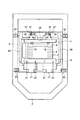
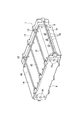
図1は本実施の形態の車両搭載型燃料電池の分解斜視図、図2は本実施の形態の車両搭載型燃料電池の平面図、図3は燃料電池スタックの斜視図、図4は燃料電池スタックの断面図である。 1 is an exploded perspective view of a vehicle-mounted fuel cell according to the present embodiment, FIG. 2 is a plan view of the vehicle-mounted fuel cell according to the present embodiment, FIG. 3 is a perspective view of a fuel cell stack, and FIG. 4 is a fuel cell. It is sectional drawing of a stack.
本実施の形態の車両搭載型燃料電池は、図1及び図2に示すように、主として複数個の燃料電池スタック1を所定数積層(本実施の形態では3つ)してなる燃料電池スタックブロック2と、この燃料電池スタックブロック2を内部に収納して保護すると共に、車両の一部である車両フレーム3に固定するためのスタックケース4と、このスタックケース4内に水や塵埃などが入り込まないようにするためのフタ36とから構成されている。
As shown in FIGS. 1 and 2, the vehicle-mounted fuel cell according to the present embodiment is mainly a fuel cell stack block in which a predetermined number of
燃料電池スタック1は、図3及び図4に示すように、起電力を生じる単位電池としての燃料電池単セル5を所定数だけ積層した積層体6とし、その積層体6の両端に、各燃料電池単セル5で発電した電流を集める集電板7、該集電板7に対する電気的絶縁を図る絶縁板8および積層体6に均一な面圧を掛けるためのエンドプレート9を配置した構成とされている。
As shown in FIGS. 3 and 4, the
燃料電池単セル5は、固体高分子電解質膜と、この固体高分子電解質膜を挟んでその両側に設けられるアノードガス拡散層(燃料極)及びカソードガス拡散層(空気極)とからなる膜電極接合体(MEA:membrane electrode assembly)と、燃料ガス及び酸化剤ガス並び冷却水などを流通させる流路を形成したセパレータとの積層体として構成され、燃料極と空気極に供給した燃料ガスと酸化剤ガスとの反応により発電する。
The fuel cell
なお、エンドプレート9が樹脂材料または基材表面に樹脂コーティングを施してなる非導電性材料で形成されている場合は、集電板7の外側に配置した絶縁板8は不要となり、絶縁構造を簡略化することができる。一方、エンドプレート9を導電体とした場合は、このエンドプレート9が集電板7の機能を持つことから前記集電板7及び絶縁板8は不要となるが、その場合は絶縁機能部材をエンドプレート9の外に設定する必要がある。
When the
そして、この燃料電池スタック1では、各燃料電池スタック1のスタック全長にばらつきが生じないようにするために、スタック全長調整手段を取り付けある。スタック全長調整手段は、テンションロッド10と、プレッシャープレート11と、燃料電池単セル5の積層方向に荷重を与える荷重付加部材である非線形弾性体12と、この非線形弾性体12の長さを可変させることにより前記積層体6へ与える荷重を調整する荷重調整部材13とからなる。
And in this
テンションロッド10は、一端を一方のエンドプレート9に固定させると共に、他方をプレッシャープレート11に固定させることにより、これらエンドプレート9とプレッシャープレート11間に亘って固定されている。本実施の形態では、エンドプレート9及びプレッシャープレート11の上下面にそれぞれ3本づつ設けると共に、左右面にそれぞれ1本づつ設けている。
The
プレッシャープレート11は、テンションロッド10が取り付けられていないエンドプレート9と相対向する位置に設けられ、このエンドプレート9と所定距離を有して配置されている。
The
非線形弾性体12は、プレッシャープレート11に取り付けられた荷重調整部材13の先端部にそれぞれ固定され、エンドプレート9を前記燃料電池単セル5の積層方向へ押圧させることにより、前記積層体6に所望の荷重を与える。かかる非線形弾性体12には、例えば非線形バネなどが使用される。
The non-linear
荷重調整部材13は、プレッシャープレート11の板厚方向に貫通して螺合するねじ調整部13Aと、このねじ調整部13Aの先端に非線形弾性体12を固定させる装着部材13Bとを有しており、このねじ調整部13Aをねじ込むことで前記非線形弾性体12の長さを可変させて前記積層体6へ与える荷重を調整する。かかるねじ調整部13Aをねじ込めば、非線形弾性体12の全長が短くなり弾発力が強まって前記積層体6を付勢する力が増大し、ねじ調整部13Bを緩めれば、非線形弾性体12の全長が次第に長くなり弾発力が弱まって前記積層体6を付勢する力が弱まる。
The
このように、スタック全長調整手段によって積層体6に燃料電池単セル5の積層方向への荷重を与えれば、燃料電池単セル5を構成するセパレータ間の接触抵抗値を所定値に確保することができ、燃料電池スタック1において出力を損なうことがない。
In this way, if a load in the stacking direction of the fuel cell
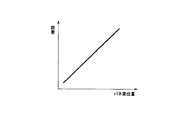
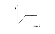
ここで、積層体6に荷重を付加する手段として非線形弾性体12を使用するは、次の理由による。例えば図5に示すようなリニアな特性を持った線形弾性体を使用した場合は、積層体6にある荷重を与えてその荷重を保持しようとすると、バネ変位量は1点でしか決まらない。すなわち、線形弾性体を用いると、積層体6の積層方向長さにおいて、各燃料電池単セル5の厚み公差の積み上げがそのまま燃料電池スタック1の全長長さ違いとなってしまう。そこで、図6に示すような特性を持った非線形弾性体12を使用すれば、一定荷重の下でほぼ均一したバネ変位量となることから、任意のバネ変位量を選択することができる。したがって、図6に示す特性を持った非線形弾性体12を使用することで、一定荷重で且つ燃料電池スタック1の全長を調整することが可能となる。
Here, the non-linear
また、この燃料電池スタック1では、スタックケース4内での実装密度を上げるために可能な限り距離を詰めて積層したいが、隣り合う燃料電池スタック1間の絶縁が問題となる。本実施の形態では、これら上下に積層配置される燃料電池スタック1の少なくとも積層体6、集電板7及び絶縁板8を、絶縁性に優れた絶縁部材である絶縁被覆板14で覆うようにする。絶縁被覆板14は、積層体6、集電板7及び絶縁板8の上下面及び両側面を覆うように全体を包み込むようにして設けられ、前後のエンドプレート9、9にそれぞれボルト15によって固定される。
Further, in this
また、これら積層体6、集電板7及び絶縁板8を絶縁被覆板14で完全に覆ってしまうと、絶縁被覆板14と燃料電池単セル5(特にセパレータ)との間に、運転中セパレータから発生する水蒸気が逃げず、運転後冷えて凝縮された水が溜まり絶縁抵抗が保持できなくなる恐れがある。そのため、本実施の形態では、絶縁被覆板14の絶縁機能上問題のない箇所に窓部16を設け、運転中セパレータから発生する水蒸気を逃がす機能を持たせている。本実施の形態では、燃料電池単セル5の積層方向と略直交する前記燃料電池スタック1の側面に窓部16を3箇所形成し、その窓部16から前記水蒸気を外部へ放出させている。
Further, when the
そして、このように構成された燃料電池スタック1の複数個は、出来る限り間隔を詰めて上下に積層配置した、いわゆる3列構成の燃料電池スタックブロック2を構成する。燃料電池スタックブロック2は、燃料ガス、酸化剤ガス及び冷却水などの流体を各燃料電池スタック1に分配させる分配マニホールド17と燃料電池スタック連結プレート18とを、当該燃料電池スタック1の積層方向両端面にそれぞれ固定させることで一体化させている。
A plurality of the
分配マニホールド17は、各燃料電池スタック1に燃料ガス、酸化剤ガス及び冷却水を分配する機能と、これら3つの燃料電池スタック1を連結させる機能を有している。この分配マニホールド17には、各燃料電池スタック1に形成された燃料ガス流路、酸化剤ガス流路及び冷却水流路とそれぞれ接続する各流路群が形成されている。それら流路群のうち、例えば、燃料ガスを供給するための燃料ガス供給流路19を図7に示した。
The
また、この分配マニホールド17には、燃料ガス、酸化剤ガス及び冷却水の出入口となる流体出入口20A、20B、20Cが形成されている。これら流体出入口20A、20B、20Cは、主面17aから外方へ突出して形成されており、図示を省略する外部配管と接続される。
The
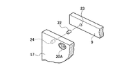
そして、この分配マニホールド17と各燃料電池スタック1とは、フロント側ボルト21によって互いに固定される。また、図8に示すように、これら分配マニホールド17と燃料電池スタック1は、互いの流路同士が位置ずれを生じることがないように、第1の位置決め固定手段である位置決めピン22にて結合される。かかる位置決めピン22は、各燃料電池スタック1に形成された孔部23と、分配マニホールド17に形成された孔部24にそれぞれ挿入され、お互いの相対位置を高精度に位置出しする。
The
このように、分配マニホールド17と各燃料電池スタック1とは、位置決めピン22にて連結結合されることから、燃料電池スタック1が複数列となっても分配マニホールド17に対する該燃料電池スタック1の取り付け位置が自ずと決まり、分配マニホールド17から燃料電池スタック1への流体の導入部分および排出部分に段差を生じさせることなく滑らかに接続させることができる。
Thus, since the
燃料電池スタック連結プレート18は、後述する位置決めピン25とで第2の位置決め固定手段を構成し、各燃料電池スタック1のプレッシャープレート11に形成された溝部23に嵌め込まれることにより各燃料電池スタック1を一体化させる。この燃料電池スタック連結プレート18は、リア側ボルト24によって前記燃料電池スタック1に固定され、さらに位置決めピン25にて結合される。かかる位置決めピン25は、各燃料電池スタック1に形成された孔部(図示は省略する)と、燃料電池スタック連結プレート18に形成された孔部26にそれぞれ挿入され、お互いの相対位置を高精度に位置出しする。
The fuel cell
このように、分配マニホールド17が取り付けられていない前記燃料電池スタック1の積層方向他側面に、燃料電池スタック連結プレート18を位置決めピン22にて位置決めして各燃料電池スタック1を一体化させているので、各燃料電池スタック1を可能な限り接近させて積層配置させることができる。したがって、燃料電池スタック1の複数個を高実装密度化させることができると共に、燃料電池スタックブロック2を小型化できる。また、この燃料電池スタック連結プレート18を前記燃料電池スタックブロック2の積層方向他側面に取り付けたことで、不要なストレスが掛かることがない。
Thus, the fuel cell
また、この燃料電池スタックブロック2には、燃料電池スタック1の分配マニホールド17が取り付けられない側面に掛かる荷重の受けとなる支持部材27が取り付けられている。かかる支持部材27は、各プレッシャープレート11に対して固定ボルト28によって固定される。これら支持部材27は、前記燃料電池スタック連結プレート18の両側にそれぞれ取り付けられる。
In addition, a
スタックケース4は、内部に燃料電池スタックブロック2を収納させるに足る大きさとされ、上方を開口させた矩形状をなす収納容器として形成されている。かかるスタックケース4は、例えば軽量化などを目的として鍛造アルミニウム合金で形成される。また、このスタックケース4には、燃料電池スタックブロック2の荷重を受けると共に外部からの振動入力や衝撃入力も受けることから、これらの荷重に耐え得るために必要な箇所に機械的強度を高めるためのリブ29が形成されている。本実施の形態では、スタックケース4の内側底面両サイドとスタックケース4の内側両側面にそれぞれ矩形状をなす肉厚の突条としたリブ29を形成している。
The stack case 4 is sized to accommodate the fuel
このように形成されたスタックケース4には、前記した燃料電池スタックブロック2がその内部に収納され、該スタックケース4の外側より固定ボルト30にて前記燃料電池スタックブロック2が固定される。また、前記した支持部材27に固定ボルト31を挿入させ、その固定ボルト31をスタックケース4の内側底面に形成したネジ孔32に螺合させることで、前記燃料電池スタックブロック2をスタックケース4に固定させる。
In the stack case 4 thus formed, the fuel
また、スタックケース4には、該スタックケース4を車両フレーム3に搭載するためのマウント部材33が固定ボルト34によってその外側壁に固定されている。さらに、このマウント部材33と車両フレーム3との間には、絶縁断熱部材35が配置されている。かかる絶縁断熱部材35は、樹脂などの非導電性及び非電熱性部材から形成され、車両フレーム3に対して絶縁構造とされている。このように、スタックケース4を車両フレーム3に搭載する際に、絶縁断熱機能を持たせた絶縁断熱部材35をマウント部材33と車両フレーム3との間に入れることで、燃料電池スタック1の熱が燃料電池スタック1の外に逃げないため、特に氷点下起動時における燃料電池暖気運転時間の短縮を図ることができる。
A mounting
なお、絶縁断熱部材35は、燃料電池スタック1の熱が外部へ逃げないようにするためにも、前記燃料電池スタックブロック2とスタックケース4との固定部分にも設けることが望ましい。
It is desirable that the insulating
前記フタ36は、燃料電池スタックブロック2を内部に収容したスタックケース4の上方開口を閉塞するようにして、図示を省略するシール部材を介して固定ボルトにて当該スタックケース4に固定される。かかるフタ36は、車両の外部からスタックケース4内に塵埃や水などが進入するのを防止する役目をする。
The
本実施の形態によれば、各燃料電池スタック1を分配マニホールド17に対して所定位置に固定させるための第1の位置決め固定手段である位置決めピン22を設けたので、燃料電池スタック1及び分配マニホールド17のそれぞれに形成された、燃料ガスや酸化剤ガスなどの流体が流通する流路の互いの位置ずれを減少させることができ、滑らかに流体を流すことがきる。
According to the present embodiment, since the positioning pins 22 as the first positioning fixing means for fixing each
また、本実施の形態によれば、分配マニホールド17が取り付けられない燃料電池スタック1の積層方向他側面にも第2の位置決め用手段である位置決めピン25及び燃料電池スタック連結プレート18を設けたことにより、分配マニホールド17が接続されない側の位置も決まり、各燃料電池スタック1の位置をその両側の位置で規定することで、不要なストレスを燃料電池スタック1に加えることなく複数積層した燃料電池スタックブロック2を構成できるという効果がある。
Further, according to the present embodiment, the positioning pins 25 and the fuel cell
また、本実施の形態によれば、分配マニホールド17が取り付けられていない側のエンドプレート9と、このエンドプレート9のさらに外側に配置されたプレッシャープレート11の間に、燃料電池スタック1の全長を調整するスタック全長調整手段を設けたので、各燃料電池スタック1に掛かる荷重を一定にしたまま全ての燃料電池スタック1の全長を揃えることが可能となる。そのため、例えば、燃料電池スタックブロック2を天地方向に配置する場合(図1の状態)において、前記した燃料電池スタック連結プレート18を複数用いることなく、一部品で各燃料電池スタック1を位置決めさせることができる。したがって、部品点数の削減並びに軽量化を図ることができる。
Further, according to the present embodiment, the entire length of the
また、本実施の形態によれば、スタックケース4にリブ29を設けたので、当該スタックケース4の機械的強度を高めることができ、積層構造とされた燃料電池スタックブロック2の荷重を受け止めることが可能となり、また車両フレーム3からの振動入力や衝撃入力にも耐え得るケース剛性を確保することができる。
Further, according to the present embodiment, since the
また、本実施の形態によれば、分配マニホールド17が取り付けられていない燃料電池スタック1の積層方向他側面に、スタックケース4への取り付け部となる支持部材27を設けたので、この支持部材27をスタックケース4の底面に直接載せて取り付けることができる。
Further, according to the present embodiment, the
また、本実施の形態によれば、各燃料電池スタック1において、電位が立つ燃料電池単セル5を積層させた部分を絶縁被覆板14で被覆しているので、各燃料電池スタック1のお互いの距離を縮めることが可能となり、全体としての実装密度を高めることができる。
In addition, according to the present embodiment, in each
また、本実施の形態によれば、各燃料電池スタック1に形成された絶縁被覆板14のうち、燃料電池単セル5の積層方向と略直交する側面に窓部16を形成したので、燃料電池スタック1から発生する水蒸気を、この窓部16を介して外部へ排出させることできる。その結果、燃料電池運転後などのタイミングで燃料電池が冷え凝縮水が絶縁被覆板14と燃料電池スタック1間に溜まり、絶縁が出来なくなることを防止できる。
In addition, according to the present embodiment, the
また、本実施の形態によれば、燃料電池スタックブロック2とスタックケース4間、またはマウント部材33と車両フレーム3との間に、樹脂等の非電導性及び非電熱性からなる絶縁断熱部材35を設けたので、絶縁構造が取り易くなり、また燃料電池スタック1からの熱を断熱し、例えば氷点下起動時等に迅速に燃料電池スタック1を暖記することが可能になる。
Further, according to the present embodiment, the insulating
また、本実施の形態によれば、エンドプレート9を樹脂材料等の非電導性材料で形成したことにより、集電板7の側面に設けた絶縁板8を不要とすることができるなど、燃料電池スタックの絶縁構造を簡略化することが可能となり、より一層実装密度を高めることができる。
Further, according to the present embodiment, since the
[その他の実施の形態]
以上、本発明を適用した具体的な実施の形態について説明したが、本発明は上述の実施の形態に制限されることなく種々の変更が可能である。
[Other embodiments]
Although specific embodiments to which the present invention is applied have been described above, the present invention is not limited to the above-described embodiments, and various modifications can be made.
例えば、上述の実施の形態では、マウント部材33をスタックケース4に固定ボルト34によって固定させたが、図9に示すように、マウント部材33をスタックケース4に一体的に形成してもよい。マウント部材33をスタックケース4に一体化させれば、部品点数を削減することができ、コストダウンを実現できる。
For example, in the above-described embodiment, the
また、上述の実施の形態では、プレッシャープレート11と支持部材27とを別体としたが、図10に示すように、プレッシャープレート11と支持部材27A、27B、27Cを一体化させてもよい。この例では、3つのプレッシャープレート11を重ね合わせたときに一つの支持部材27を構成するように、各プレッシャープレート11に分割された支持部材27A、27B、27Cを一体化させている。
In the above-described embodiment, the
各支持部材27A、27B、27Cには、3つのプレッシャープレート11を連結させるためのプレート固定ボルト37が挿通されるプレート連結孔38と、燃料電池スタックブロック2をスタックケース4に固定させるための固定ボルト31が挿通されるブロック固定孔39が形成されている。
Each
このように、プレッシャープレート11に支持部材27A、27B、27Cを一体化させることで、さらなる部品点数の削減を図ることができる。
Thus, by integrating the
1…燃料電池スタック
2…燃料電池スタックブロック
3…車両フレーム(車両)
4…スタックケース
6…積層体
7…集電板
8…絶縁板
9…エンドプレート
10…テンションロッド
11…プレッシャープレート
12…非線形弾性体
13…荷重調整部材
14…絶縁被覆板
16…窓部
17…分配マニホールド
18…燃料電池スタック連結プレート(第2の位置決め手段)
22…位置決めピン(第1の位置決め手段)
25…位置決めピン(第2の位置決め手段)
29…リブ
33…マウント部材
35…絶縁断熱部材
DESCRIPTION OF
DESCRIPTION OF SYMBOLS 4 ...
22 ... Positioning pin (first positioning means)
25 ... Positioning pin (second positioning means)
29 ...
Claims (8)
前記燃料電池スタックの積層方向一側面に取り付けられ、該燃料電池スタックの複数個を車両の上下方向に所定間隔を置いて積層固定させ、且つ各燃料電池スタックに少なくとも前記燃料ガス及び酸化剤ガスを供給する全積層体共通の分配マニホールドと、
前記分配マニホールドが取り付けられた前記燃料電池スタックの積層体を内部に収納させ、車両に固定するためのスタックケースと、
前記各燃料電池スタックを前記分配マニホールドに対して所定位置に位置決め固定させる第1の位置決め固定手段と、
前記分配マニホールドが取り付けられていない前記燃料電池スタックの積層方向他側面に、前記各燃料電池スタックを所定位置に位置決め固定させる第2の位置決め固定手段とを備えており、
前記第1の位置決め固定手段は、各燃料電池スタックに形成された孔部と、前記分配マニホールドに形成された孔部にそれぞれ挿入されて互いの相対位置を位置出しする位置決めピンからなり、
前記第2の位置決め固定手段は、各燃料電池スタックに形成された溝部に嵌め込まれて該各燃料電池スタックを一体化させる連結プレートと、各燃料電池スタックに形成された孔部と該連結プレートに形成された孔部にそれぞれ挿入されて各燃料電池スタックの相対位置を位置出しする位置決めピンとから構成されてなる
ことを特徴とする車両搭載型燃料電池。 A fuel cell stack in which a predetermined number of fuel cell single cells as unit cells that generate electric power by reaction of fuel gas and oxidant gas are stacked, and at least end plates are attached to both ends thereof;
A plurality of fuel cell stacks are attached to one side surface in the stacking direction of the fuel cell stacks, and are stacked and fixed at predetermined intervals in the vertical direction of the vehicle. A distribution manifold common to all laminates to be supplied,
A stack case for accommodating the stack of the fuel cell stack to which the distribution manifold is attached and fixing the stack to a vehicle;
First positioning and fixing means for positioning and fixing each fuel cell stack at a predetermined position with respect to the distribution manifold;
A second positioning and fixing means for positioning and fixing each fuel cell stack at a predetermined position on the other side in the stacking direction of the fuel cell stack to which the distribution manifold is not attached;
The first positioning and fixing means includes a hole formed in each fuel cell stack and a positioning pin that is inserted into each of the holes formed in the distribution manifold and positions relative positions of each other.
The second positioning and fixing means includes a connecting plate that is fitted into a groove formed in each fuel cell stack to integrate the fuel cell stack, a hole formed in each fuel cell stack, and the connecting plate. A vehicle-mounted fuel cell, characterized by comprising positioning pins that are inserted into the formed holes to position the relative positions of the fuel cell stacks .
前記分配マニホールドが取り付けられていない側の前記エンドプレートと、このエンドプレートのさらに外側に配置されたプレッシャープレートとの間に、前記燃料電池スタックの全長を調整するスタック全長調整手段を設けた
ことを特徴とする車両搭載型燃料電池。 The vehicle-mounted fuel cell according to claim 1,
A stack total length adjusting means for adjusting the total length of the fuel cell stack is provided between the end plate on the side where the distribution manifold is not attached and a pressure plate arranged further outside the end plate. A vehicle-mounted fuel cell.
前記スタックケースの内側に、機械的強度を高めるリブを設けた
ことを特徴とする車両搭載型燃料電池。 The vehicle-mounted fuel cell according to claim 1 or 2,
A vehicle-mounted fuel cell, characterized in that a rib for increasing mechanical strength is provided inside the stack case.
前記分配マニホールドが取り付けられていない前記燃料電池スタックの積層方向他側面に、前記スタックケースへの取り付け部となる支持部材が固定されている
ことを特徴とする車両搭載型燃料電池。 A vehicle-mounted fuel cell according to any one of claims 1 to 3, comprising:
A vehicle-mounted fuel cell, wherein a support member serving as an attachment portion to the stack case is fixed to the other side surface in the stacking direction of the fuel cell stack to which the distribution manifold is not attached.
前記各燃料電池スタックは、少なくとも前記燃料電池単セルを積層させた部分を絶縁部材で被覆している
ことを特徴とする車両搭載型燃料電池。 A vehicle-mounted fuel cell according to any one of claims 1 to 4, comprising:
Each of the fuel cell stacks covers at least a portion where the fuel cell single cells are stacked with an insulating member.
前記各燃料電池スタックに形成された絶縁部材のうち、前記燃料電池単セルの積層方向と略直交する側面に窓部を形成した
ことを特徴とする車両搭載型燃料電池。 The vehicle-mounted fuel cell according to claim 5,
Of the insulating members formed in each of the fuel cell stacks, a window portion is formed on a side surface substantially orthogonal to the stacking direction of the fuel cell single cells.
前記燃料電池スタックの積層体と前記スタックケースとの間、または、スタックケースを車両に取り付けるためのマウント部材と車両マウント部との間に、非電導性及び非電熱性からなる絶縁断熱部材を設けた
ことを特徴とする車両搭載型燃料電池。 A vehicle-mounted fuel cell according to any one of claims 1 to 6, comprising:
An insulating heat insulating member made of non-conductive and non-electrically conductive is provided between the stack of the fuel cell stack and the stack case, or between the mount member for mounting the stack case on the vehicle and the vehicle mount part. A vehicle-mounted fuel cell characterized by the above.
前記エンドプレートを、非導電性材料で形成した
ことを特徴とする車両搭載型燃料電池。 A vehicle-mounted fuel cell according to any one of claims 1 to 7, comprising:
The vehicle-mounted fuel cell, wherein the end plate is made of a non-conductive material.
Priority Applications (1)
| Application Number | Priority Date | Filing Date | Title |
|---|---|---|---|
| JP2004220133A JP4635503B2 (en) | 2004-07-28 | 2004-07-28 | Vehicle-mounted fuel cell |
Applications Claiming Priority (1)
| Application Number | Priority Date | Filing Date | Title |
|---|---|---|---|
| JP2004220133A JP4635503B2 (en) | 2004-07-28 | 2004-07-28 | Vehicle-mounted fuel cell |
Publications (2)
| Publication Number | Publication Date |
|---|---|
| JP2006040752A JP2006040752A (en) | 2006-02-09 |
| JP4635503B2 true JP4635503B2 (en) | 2011-02-23 |
Family
ID=35905518
Family Applications (1)
| Application Number | Title | Priority Date | Filing Date |
|---|---|---|---|
| JP2004220133A Expired - Lifetime JP4635503B2 (en) | 2004-07-28 | 2004-07-28 | Vehicle-mounted fuel cell |
Country Status (1)
| Country | Link |
|---|---|
| JP (1) | JP4635503B2 (en) |
Cited By (2)
| Publication number | Priority date | Publication date | Assignee | Title |
|---|---|---|---|---|
| KR101610115B1 (en) * | 2014-08-01 | 2016-04-08 | 현대자동차 주식회사 | Fuel cell stack |
| JP7251913B2 (en) | 2017-06-28 | 2023-04-04 | トヨタ自動車株式会社 | Machine design method |
Families Citing this family (23)
| Publication number | Priority date | Publication date | Assignee | Title |
|---|---|---|---|---|
| JP5098493B2 (en) * | 2006-08-28 | 2012-12-12 | トヨタ自動車株式会社 | Assembly inspection system for fuel cells |
| JP2008071508A (en) * | 2006-09-12 | 2008-03-27 | Matsushita Electric Ind Co Ltd | Polymer electrolyte fuel cell |
| JP5092360B2 (en) * | 2006-11-17 | 2012-12-05 | 富士電機株式会社 | Fuel cell power generator |
| JP5103893B2 (en) * | 2006-12-20 | 2012-12-19 | トヨタ自動車株式会社 | Fuel cell moving body |
| JP4928251B2 (en) * | 2006-12-26 | 2012-05-09 | 本田技研工業株式会社 | Fuel cell stack |
| JP5189302B2 (en) | 2007-03-14 | 2013-04-24 | 本田技研工業株式会社 | Fuel cell system |
| JP5099680B2 (en) * | 2007-03-30 | 2012-12-19 | 本田技研工業株式会社 | Fuel cell motorcycle |
| JP5076681B2 (en) * | 2007-06-29 | 2012-11-21 | 日産自動車株式会社 | Fuel cell assembly apparatus and assembly method, and fuel cell assembled by the assembly method |
| JP5214298B2 (en) * | 2008-03-26 | 2013-06-19 | 本田技研工業株式会社 | Fuel cell system |
| JP5363754B2 (en) * | 2008-04-11 | 2013-12-11 | 本田技研工業株式会社 | Fuel cell system |
| JP5482839B2 (en) * | 2012-07-23 | 2014-05-07 | トヨタ自動車株式会社 | Fuel cell module for vehicles |
| DE102012024964A1 (en) * | 2012-12-20 | 2014-06-26 | Daimler Ag | Housing for a fuel cell stack |
| JP6146395B2 (en) * | 2014-11-13 | 2017-06-14 | トヨタ自動車株式会社 | Fuel cell module |
| JP6142863B2 (en) | 2014-11-14 | 2017-06-07 | トヨタ自動車株式会社 | Fuel cell case |
| CN110061278B (en) * | 2018-01-18 | 2024-08-02 | 宇通客车股份有限公司 | Vehicle and fuel cell packaging shell thereof |
| JP6939631B2 (en) | 2018-02-20 | 2021-09-22 | トヨタ自動車株式会社 | Fuel cell and vehicle equipped with it |
| JP7336304B2 (en) * | 2019-08-02 | 2023-08-31 | 日産自動車株式会社 | Support structure for fuel cell system |
| JP7478525B2 (en) * | 2019-09-11 | 2024-05-07 | 日産自動車株式会社 | Fuel cell unit support structure |
| JP7216132B2 (en) * | 2021-03-15 | 2023-01-31 | 本田技研工業株式会社 | Stack case and stack case assembly method |
| JP7647419B2 (en) * | 2021-07-26 | 2025-03-18 | 日産自動車株式会社 | Vehicle fuel cell system |
| CN114464837B (en) * | 2021-10-08 | 2024-01-16 | 东风汽车集团股份有限公司 | Fuel cell system and assembly process |
| CN114464861B (en) * | 2021-10-08 | 2024-01-16 | 东风汽车集团股份有限公司 | A fuel cell housing and fuel cell |
| CN115312824B (en) * | 2022-07-20 | 2024-07-12 | 东风汽车集团股份有限公司 | Fuel cell packaging structure, fuel cell module and assembly method thereof, and vehicle |
Family Cites Families (5)
| Publication number | Priority date | Publication date | Assignee | Title |
|---|---|---|---|---|
| JP3878679B2 (en) * | 1994-12-08 | 2007-02-07 | トヨタ自動車株式会社 | Fuel cell |
| JP5021110B2 (en) * | 1999-09-01 | 2012-09-05 | 本田技研工業株式会社 | Fuel cell system |
| JP3714093B2 (en) * | 2000-02-29 | 2005-11-09 | アイシン精機株式会社 | Fuel cell |
| JP2004047211A (en) * | 2002-07-10 | 2004-02-12 | Nissan Motor Co Ltd | Fuel cell system |
| JP4135455B2 (en) * | 2002-10-04 | 2008-08-20 | 日産自動車株式会社 | Mobile fuel cell system |
-
2004
- 2004-07-28 JP JP2004220133A patent/JP4635503B2/en not_active Expired - Lifetime
Cited By (2)
| Publication number | Priority date | Publication date | Assignee | Title |
|---|---|---|---|---|
| KR101610115B1 (en) * | 2014-08-01 | 2016-04-08 | 현대자동차 주식회사 | Fuel cell stack |
| JP7251913B2 (en) | 2017-06-28 | 2023-04-04 | トヨタ自動車株式会社 | Machine design method |
Also Published As
| Publication number | Publication date |
|---|---|
| JP2006040752A (en) | 2006-02-09 |
Similar Documents
| Publication | Publication Date | Title |
|---|---|---|
| JP4635503B2 (en) | Vehicle-mounted fuel cell | |
| JP4672892B2 (en) | Fuel cell stack | |
| US7070872B2 (en) | Fuel cell stack | |
| US8197984B2 (en) | Fuel cell stack | |
| US10033062B2 (en) | Fuel cell stack and mount structure therefor | |
| JP4653978B2 (en) | Fuel cell stack | |
| JPH11233132A (en) | Fuel cell fastening structure | |
| JPH08130028A (en) | Solid polymer electrolyte fuel cell | |
| JP2012059563A (en) | Fuel cell stack | |
| JP2006040753A (en) | Vehicle-mounted fuel cell | |
| JP2007128752A (en) | Fuel cell stack, fuel cell system, and mobile body equipped with the system | |
| JP2006040717A (en) | Fuel cell device | |
| JP6986000B2 (en) | Fuel cell stack and end plate | |
| JP2014071943A (en) | On-vehicle fuel cell system | |
| JP4564273B2 (en) | Fuel cell stack | |
| JP4417204B2 (en) | Fuel cell stack | |
| CN100517848C (en) | Thermal stress tolerant fuel cell assembly within a housing | |
| US12381237B2 (en) | Fuel cell stack | |
| US10186727B2 (en) | Fuel cell stack | |
| JP6469351B2 (en) | Fuel cell stack | |
| JP2006172850A (en) | Fuel cell stack | |
| JP4430311B2 (en) | Fuel cell stack | |
| JP4664020B2 (en) | Manufacturing method of fuel cell stack | |
| JP6605107B2 (en) | Fuel cell stack | |
| JP2000294268A (en) | Fuel cell fastening structure |
Legal Events
| Date | Code | Title | Description |
|---|---|---|---|
| A621 | Written request for application examination |
Free format text: JAPANESE INTERMEDIATE CODE: A621 Effective date: 20070625 |
|
| A977 | Report on retrieval |
Free format text: JAPANESE INTERMEDIATE CODE: A971007 Effective date: 20100531 |
|
| A131 | Notification of reasons for refusal |
Free format text: JAPANESE INTERMEDIATE CODE: A131 Effective date: 20100608 |
|
| A521 | Request for written amendment filed |
Free format text: JAPANESE INTERMEDIATE CODE: A523 Effective date: 20100728 |
|
| A131 | Notification of reasons for refusal |
Free format text: JAPANESE INTERMEDIATE CODE: A131 Effective date: 20100817 |
|
| A521 | Request for written amendment filed |
Free format text: JAPANESE INTERMEDIATE CODE: A523 Effective date: 20101006 |
|
| TRDD | Decision of grant or rejection written | ||
| A01 | Written decision to grant a patent or to grant a registration (utility model) |
Free format text: JAPANESE INTERMEDIATE CODE: A01 Effective date: 20101026 |
|
| A01 | Written decision to grant a patent or to grant a registration (utility model) |
Free format text: JAPANESE INTERMEDIATE CODE: A01 |
|
| A61 | First payment of annual fees (during grant procedure) |
Free format text: JAPANESE INTERMEDIATE CODE: A61 Effective date: 20101108 |
|
| FPAY | Renewal fee payment (event date is renewal date of database) |
Free format text: PAYMENT UNTIL: 20131203 Year of fee payment: 3 |
|
| R150 | Certificate of patent or registration of utility model |
Ref document number: 4635503 Country of ref document: JP Free format text: JAPANESE INTERMEDIATE CODE: R150 Free format text: JAPANESE INTERMEDIATE CODE: R150 |
|
| EXPY | Cancellation because of completion of term |