JP2007128752A - Fuel cell stack, fuel cell system, and moving vehicle mounted with this system - Google Patents
Fuel cell stack, fuel cell system, and moving vehicle mounted with this system Download PDFInfo
- Publication number
- JP2007128752A JP2007128752A JP2005320622A JP2005320622A JP2007128752A JP 2007128752 A JP2007128752 A JP 2007128752A JP 2005320622 A JP2005320622 A JP 2005320622A JP 2005320622 A JP2005320622 A JP 2005320622A JP 2007128752 A JP2007128752 A JP 2007128752A
- Authority
- JP
- Japan
- Prior art keywords
- fuel cell
- frame
- stack
- relay
- cell stack
- Prior art date
- Legal status (The legal status is an assumption and is not a legal conclusion. Google has not performed a legal analysis and makes no representation as to the accuracy of the status listed.)
- Granted
Links
Images


Classifications
-
- Y—GENERAL TAGGING OF NEW TECHNOLOGICAL DEVELOPMENTS; GENERAL TAGGING OF CROSS-SECTIONAL TECHNOLOGIES SPANNING OVER SEVERAL SECTIONS OF THE IPC; TECHNICAL SUBJECTS COVERED BY FORMER USPC CROSS-REFERENCE ART COLLECTIONS [XRACs] AND DIGESTS
- Y02—TECHNOLOGIES OR APPLICATIONS FOR MITIGATION OR ADAPTATION AGAINST CLIMATE CHANGE
- Y02E—REDUCTION OF GREENHOUSE GAS [GHG] EMISSIONS, RELATED TO ENERGY GENERATION, TRANSMISSION OR DISTRIBUTION
- Y02E60/00—Enabling technologies; Technologies with a potential or indirect contribution to GHG emissions mitigation
- Y02E60/30—Hydrogen technology
- Y02E60/50—Fuel cells
Abstract
Description
本発明は、燃料電池スタック、燃料電池システムおよび同システムを搭載する移動体に関する。 The present invention relates to a fuel cell stack, a fuel cell system, and a moving body equipped with the system.
近年、燃料電池車のひとつとして、燃料電池スタックのセル積層方向の一端面に高電圧リレーを設け、他端面に冷却媒体の流路や反応ガス流路を接続したものが開示されている(例えば、特許文献1参照)。この燃料電池自動車のように燃料電池スタックに高電圧リレーを一体に設けることの利点としては、燃料電池スタックの出力端子から高電圧リレーまでの距離が短くなるので、リレー遮断時に高電圧状態となる部位がその分だけ少なくなるということがある。
しかしながら、従来構造のスタックの場合、セル積層方向の端面が小さくなれば、反応ガスの配管(例えば、水素供給配管及び排出配管、酸化剤供給配管及び排出配管)や冷媒配管、スタック荷重機構など、燃料電池の発電を行うために必要な部品を狭いスペースの中で効率よく配置または接続することが困難になる。特に高電圧リレーはそのリレーが扱う電力の大きさから小型化に限界があるため、配置することは困難である。また、リレーがスタックに接続する配管等の他の部品やスタック周辺の他の部品と干渉する可能性がある。 However, in the case of a stack having a conventional structure, if the end face in the cell stacking direction becomes smaller, the reaction gas pipe (for example, hydrogen supply pipe and discharge pipe, oxidant supply pipe and discharge pipe), refrigerant pipe, stack load mechanism, etc. It becomes difficult to efficiently arrange or connect components necessary for generating power from the fuel cell in a narrow space. In particular, high voltage relays are difficult to arrange because there is a limit to miniaturization due to the amount of power handled by the relays. In addition, the relay may interfere with other parts such as piping connected to the stack and other parts around the stack.
そこで、本発明は、さらなる小型化の実現を可能とする構造の燃料電池スタック、燃料電池システムおよび同システムを搭載する移動体を提供することを目的とする。 Accordingly, an object of the present invention is to provide a fuel cell stack, a fuel cell system, and a mobile body equipped with the system having a structure capable of realizing further miniaturization.
本発明にかかる請求項1に記載の発明は、複数のセルが積層されたスタック本体と、前記スタック本体の周囲を囲むフレームと、前記フレームの両端部にそれぞれ固定され、前記フレームの内側に空間を画成するエンドプレートと、前記スタック本体に設けられた電力出力端子に接続されたリレーと、を備える燃料電池スタックであって、前記リレーは、前記スタック本体の上方または下方に設けられていることを特徴としている。 According to the first aspect of the present invention, there is provided a stack main body in which a plurality of cells are stacked, a frame surrounding the stack main body, and both ends of the frame, and a space inside the frame. And a relay connected to a power output terminal provided in the stack body, wherein the relay is provided above or below the stack body. It is characterized by that.
請求項2に記載の発明は、請求項1に記載の燃料電池スタックにおいて、前記リレーは、前記フレームの外側の上面または下面、もしくは前記フレームの内側の天井面または底面に配置されていることを特徴としている。 According to a second aspect of the present invention, in the fuel cell stack according to the first aspect, the relay is disposed on an upper surface or a lower surface outside the frame, or a ceiling surface or a bottom surface inside the frame. It is a feature.
請求項3に記載の発明は、請求項1または2に記載の燃料電池スタックにおいて、前記スタック本体のセル積層方向の少なくとも一端部に反応ガスを供給する反応ガス供給装置を備えることを特徴としている。
The invention according to
リレーの配置に特徴を有する本発明にかかる燃料電池スタックは、スタック側面に配置されていた従前の構造に対して以下のような点で特徴的である。すなわち、燃料電池スタックに対してガス配管や冷媒配管などの接続をする場合、あるいはこれらを燃料電池スタックの周囲に配置する場合において従来構造の場合よりも有利となりうるから、燃料電池スタックのさらなる小型化を実現しやすくなるという利点がある。また、当該燃料電池スタックを含む燃料電池システム、あるいはこれが搭載される移動体についてはますますの小型化・高密度化が進む状況下では、電気系と液体系とを分離した構造をとりつつ、密度の高い狭小スペースに当該リレーを配置しなければならない状況ないしは要請が生じる可能性が十分にあるが、本発明によればこのような状況に対応し、かかる要請に応えることが可能になる。また、小型化・高密度化がさらに進む場合、当該燃料電池スタックとその周囲に配置される配管等の他部材とが例えば振動時に干渉しあう事態も起こりうるが、スタック自体の小型化および配管等の接続や配置の容易化を図った本発明によればこのような事態を抑制することも可能である。また、さらなる小型化・高密度化の実現はデッドスペースの有効利用にもつながる。 The fuel cell stack according to the present invention, which is characterized by the arrangement of relays, is characteristic in the following points with respect to the conventional structure arranged on the side surface of the stack. That is, when connecting gas piping, refrigerant piping, or the like to the fuel cell stack, or when these are arranged around the fuel cell stack, it can be more advantageous than the conventional structure. There is an advantage that it is easy to realize. In addition, in a situation where the fuel cell system including the fuel cell stack or the mobile body on which the fuel cell stack is mounted is increasingly miniaturized and densified, while taking a structure in which the electric system and the liquid system are separated, Although there is a possibility that a situation or a request for arranging the relay in a narrow space with high density may occur, according to the present invention, it becomes possible to respond to such a request in response to such a situation. In addition, when further downsizing and higher density occur, the fuel cell stack and other members such as pipes arranged around the fuel cell stack may interfere with each other during vibration, for example. According to the present invention that facilitates connection and arrangement of the above, such a situation can be suppressed. In addition, realization of further miniaturization and higher density leads to effective use of dead space.
また、請求項4に記載の燃料電池システムは、上記の燃料電池スタックと、前記スタック本体に反応ガスを供給する反応ガス供給装置とを備えることを特徴としている。 According to a fourth aspect of the present invention, there is provided a fuel cell system including the fuel cell stack and a reaction gas supply device that supplies a reaction gas to the stack body.
さらに、請求項5に記載の移動体は、上記の燃料電池システムと、前記スタック本体から電力の供給を受けて当該移動体の移動推進力を発生させるモータと、前記スタック本体に前記リレーを介して接続され、前記スタック本体が発生した電力の前記モータへの供給を制御する電力制御機器とを備えることを特徴としている。
Furthermore, the moving body according to
本発明によれば、燃料電池スタックのさらなる小型化を実現することが可能であり、しかも、ガス配管や冷媒配管などの接続、あるいは配置といった面でも有利となる。 According to the present invention, it is possible to further reduce the size of the fuel cell stack, and it is also advantageous in terms of connection or arrangement of gas piping and refrigerant piping.
以下、本発明の構成を図面に示す実施の形態の一例に基づいて詳細に説明する。 Hereinafter, the configuration of the present invention will be described in detail based on an example of an embodiment shown in the drawings.
図1〜図4に本発明の一実施形態を示す。本実施形態の燃料電池スタック1は、図2に示すように、基本単位であるセル2が複数積層されたスタック本体3と、スタック本体3を内側に収容するフレーム5とを備えている。また、本実施形態のフレーム5は、押し出し成形された金属製の筒状体であり、横断面(長手方向に垂直な断面)の形状が矩形をなしている。フレーム5には、後述するように張力が作用するので、その張力に対して十分な耐力を発揮するために、フレーム5の上下、両側の各壁部はいずれも肉厚に形成されている。フレーム5の内面には、絶縁のために樹脂製の被膜(図示略)が形成されている。なお、ここでいうフレーム5の内面とは、フレーム内側の面のみならず当該フレーム5におけるシール部(例えば、ゴム製のシールリングが嵌め込まれる溝14)の面なども含む意味である。これらシール部にもコーティングすることにより、例えばスタック本体3内にて結露が生じたとしても絶縁状態を保持することが可能となる。
1 to 4 show an embodiment of the present invention. As shown in FIG. 2, the
セル2の積層方向に沿うスタック本体3の一端には、ターミナルプレート7が配置され、その外側に絶縁プレート8が配置されている(図2参照)。スタック本体3の他端には、ターミナルプレート7が配置され、その外側に絶縁プレート8が配置され、さらにその外側にはプレッシャプレート9が配置されている。各ターミナルプレート7には、出力端子6が設けられている。
A
スタック本体3は、セル2の積層方向をフレーム5の長手方向に一致させて、フレーム5の内側に収容されている。スタック本体3とフレーム5の内面との間には、全周にわたって空隙が設けられており、スタック本体3をフレーム5の内側に収め易くなっている。
The
フレーム5の両端部たとえば両端面には、図2に示すように、フレーム5の内側に空間を画成するエンドプレート10a,10bがそれぞれ固定されている。エンドプレート10a,10bは、フレーム5の断面形状に合致する矩形をなす樹脂製の板状体である。
As shown in FIG. 2,
フレーム5の両端面には、エンドプレート10a,10bを固定するために、複数のねじ穴12aが、周方向に沿って間隔を空けて設けられている(図3参照)。各ねじ穴12aは、螺入方向をフレーム5の長手方向に一致させて形成されている。一方、エンドプレート10a,10bには、各ねじ穴12aに合致するように、複数の貫通孔12bが設けられている(図2、図3参照)。位置が合致するように設けられたねじ穴12aおよび貫通孔12bには、それぞれボルトねじ13が螺着されている。
A plurality of
また、フレーム5の両端面には、各ねじ穴12aよりも内側に、フレーム5の周方向に沿って無端状の溝14が形成されている。溝14には、ゴム製のシールリング15が嵌め込まれている。このシールリング15がエンドプレート10a,10bにそれぞれ密着することにより、フレーム5の一方の端面とエンドプレート10aとの間、およびフレーム5の他方の端面とエンドプレート10bとの間がそれぞれ封止されている。
In addition,
スタック本体3の一方の端面に配置された絶縁プレート8は、一方のエンドプレート10aに当接し、スタック本体3の他方の端面に配置されたプレッシャプレート9は、他方のエンドプレート10bから離間している(図2参照)。プレッシャプレート9とエンドプレート10bとの間には、スプリングボックス11が介装されている。スプリングボックス11は、プレッシャプレート9をエンドプレート10bから遠ざける方向に付勢力を作用させており、この付勢力によって複数のセル2が締結されている。スプリングボックス11の付勢力に対する反力は、フレーム5が負担しており、これによってフレーム5には長手方向に張力が作用している。スプリングボックス11は、熱膨張やクリープ現象によってスタック本体3の積層方向の長さが変動しても、スプリングボックス11自身が弾性変形することによってその変動を吸収する。なお、エンドプレート10bとスプリングボックス11との間には、必要に応じてシム(寸法を調整する板)が介装される。
The
セル2は、詳細な図示は省略するが、イオン交換膜からなる電解質膜を一対の電極で挟んだMEA(Membrane-Electrode Assembly)と、MEAを挟む一対のセパレータとを備えている。各セパレータの基材はカーボンまたはメタルから形成されており、導電性を有している。
Although not shown in detail, the
スタック本体3には、各セル2内のMEAに酸化ガスを供給する酸化ガスマニホールドと、同じく各セル2内のMEAに燃料ガスとしての水素ガスを供給する水素ガスマニホールドと、MEAにおける酸化ガスと水素ガスとの電気化学反応によって発生する熱を回収する冷媒マニホールドとが、入口側、出口側に分かれて設けられている(ただし、これらマニホールドの図示は省略)。
The
スタック本体3の一端に配置されたエンドプレート10aには、入口側の各マニホールドに連通しスタック本体3に各種の流体を供給する流体配管16a,16b,16eと、出口側の各マニホールドに連通しスタック本体3を流通した各種の流体を排出する流体配管16c,16d,16fとが接続されている。本実施形態における流体配管16a〜16fは、いずれも樹脂製である。エンドプレート10aには、流体配管16a〜16fを挿通される6つの貫通孔が、3つずつ2列に並んで形成されており、各貫通孔と各流体配管16a〜16fとの隙間には、例えばOリングからなるシール部材17a〜17f(ただし図2においては17a〜17cのみ図示)がそれぞれ配設されている。
The
フレーム5の一方の側壁部5bには、フレーム5の長手方向に延在する長孔5dが、上下に分かれて2つ形成されている(図1参照)。上下に分かれた各長孔5dには、水素透過膜18が張設されている。長孔5dと水素透過膜18との隙間には、シール部材(図示略)が配設されている。水素透過膜18は、水は透過せずに水素のみを透過し、フレーム5の内側の空間の水素濃度を一定に保つ。また、フレーム5の内側の空間の上部には、水素濃度センサ(図示略)が設けられている。フレーム5の上壁部5cには、水素濃度センサに接続された配線を通す貫通孔(図示略)が設けられている。水素濃度センサは、フレーム5の内側の空間の水素濃度を常時監視する。上壁部5cの貫通孔と水素濃度センサの配線との間には、シール部材(図示略)が配設されている。
Two
フレーム5の上壁部5cの外面には、他方の側壁部5aに寄せて、高電圧リレー25を収容する高電圧ケース20が配設されている。高電圧ケース20は、ひとつの面が開放された直方体状の金属製の筺体である。高電圧ケース20の開放された面の周囲には、外側に張り出すフランジ21が形成されている。フランジ21には、ボルトねじ22を通すための複数の貫通孔が間隔を空けて形成されている。一方、フレーム5の上壁部5cには、これら複数の貫通孔に合致するように、複数のねじ穴が設けられている。これら複数のねじ穴は、上壁部5cの厚さ方向に向けて形成されているが、貫通はしていない。合致させた貫通孔およびねじ穴には、それぞれボルトねじ22が螺着されており、これによって上壁部5cに高電圧ケース20が固定されている。フレーム5の上壁部5cとフランジ21との間には、シール部材23が隙間なく配設されている(図2参照)。
On the outer surface of the upper wall portion 5c of the
フレーム5に取り付けられた高電圧ケース20の内側には、高電圧リレー25が内蔵されており、高電圧ケース20に覆われたフレーム5の上壁部5cには、スタック本体3の積層方向の一端に設けられた出力端子6(+端子)に接続された出力ケーブルCaと、スタック本体3の積層方向の他端に設けられた出力端子6(−端子)に接続された出力ケーブルCbとを挿通する貫通孔5eが形成されている(図2参照)。貫通孔5eに挿通された出力ケーブルCa,Cbは、上述の高電圧リレー25に接続されている。
A
高電圧ケース20には、高電圧リレー25に接続されて燃料電池スタック1の外に引き出される出力ケーブルCa’,Cb’を挿通する貫通孔26が形成されている(図2参照)。貫通孔26と出力ケーブルCa’,Cb’との間には、両者の隙間を封止するシール部材27が配設されている。出力ケーブルCa’,Cb’は、DC/DCコンバータ、インバータ、エアコンプレッサ用インバータ、水素ポンプ用インバータ、クーラントポンプ用インバータ等の電力制御機器(図示略)に接続される。
The
フレーム5の外側の上面、すなわち上壁部5cの外面には、他方の側壁部5bに寄せて、後述するセルモニタ(図示略)を収容するセルモニタケース30が配設されている。セルモニタケース30は、ひとつの面が開放された直方体状の金属製の筺体である。セルモニタケース30の開放された面の周囲には、外側に張り出すフランジ31が形成されている。フランジ31には、ボルトねじ32を通すための複数の貫通孔が間隔を空けて形成されている。一方、フレーム5の上壁部5cには、これら複数の貫通孔に合致するように、複数のねじ穴が設けられている。これら複数のねじ穴は、上壁部5cの厚さ方向に向けて形成されているが、貫通はしていない。合致させた貫通孔およびねじ穴には、それぞれボルトねじ32が螺着されており、これによって上壁部5cにセルモニタケース30が固定されている。フレーム5の上壁部5cとフランジ31との間にも、シール部材(図示略)が隙間なく配設されている。
A
図示しないが、フレーム5に取り付けられたセルモニタケース30の内側には、セルモニタを構成する基板が内蔵されており、セルモニタケース30に覆われたフレーム5の上壁部5cには、セルモニタの端子を通す貫通孔が設けられている。この貫通孔とセルモニタの端子との間には、シール部材が配設されており、セルモニタケース30の内側の空間とフレーム5の内側の空間とは隔絶されている。セルモニタの基板は、温度や湿度の変化に影響を受け易いが、これら2つの空間が隔絶されることにより、フレーム5の内側の空間の温度や湿度が変化しても、セルモニタケース30の内側の空間にはそのような状態の変化が及び難く、セルモニタの基板が健全に保たれる。
Although not shown, a substrate constituting the cell monitor is built inside the
セルモニタケース30には、セルモニタの基板に接続された配線を挿通する貫通孔が形成されている。この貫通孔とセルモニタの配線との間には、両者の隙間を封止するシール部材が配設されている。
The
なお、高電圧ケース20とセルモニタケース30とを別個に設けたのは、いずれの部材もノイズを発することから、ノイズによる影響を互いに避けるためである。
The reason why the
フレーム5に固定されたエンドプレート10a,10bの下縁には、車体と燃料電池スタック1との間に介在して燃料電池スタック1を支持するマウント40が設けられている。マウント40は、エンドプレート10aの下縁の中央にひとつ、エンドプレート10bの下縁に2つ、合計3つ設けられている。
燃料電池スタック1は、スタック本体3に酸化ガスおよび水素ガスといった反応ガスを供給する反応ガス供給装置、およびスタック本体3に冷媒を供給する冷媒供給装置とともに、燃料電池システムを構成している。そして、この燃料電池システムは、スタック本体3から電力の供給を受けて車両の移動推進力を発生させる駆動モータや反応ガス供給装置、冷媒供給装置で使用されるポンプを駆動するモータ、およびスタック本体3に高電圧リレー25を介して接続され、スタック本体3が発生した電力の上記モータへの供給を制御する電力制御機器とともに、移動体としての車体41に搭載される。
The
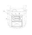
上記のように構成された燃料電池スタック1は、図4に示すように、車体41の車室前方に設けられたスタック収容空間(または収容室R)に、セルモニタケース30および高電圧ケース20が取り付けられた面を上に向け、セルモニタケース30を車体41の前側、高電圧ケース20を車体41の後側に配置し、3つのマウント40を介して固定される。
As shown in FIG. 4, the
上記のように構成された燃料電池スタック1は、車体41に、高電圧リレー25が取り付けられた面を上にして取り付けられているので、高電圧リレー25は周囲の他の部品との干渉が回避されるので破損が抑制される。このように、高電圧リレー25が破損し難いので、燃料電池がショートする危険を回避することができる。
Since the
また、本実施形態の燃料電池システムにおいては、スタック本体3が、フレーム5とエンドプレート10a,10bとによってフレーム5の内部に画成された空間に収容され、さらにフレーム5がスプリングボックス11の反力を負担する構造部材として機能するので、燃料電池スタック1は従来のものと比較して小型である。
Further, in the fuel cell system of the present embodiment, the
また、スタック本体3を支持するエンドプレート10a,10b、およびスタック本体3に接続される流体配管16a〜16fがいずれも樹脂製なので、スタック本体3を周囲の部材から電気的に切り離して絶縁することができる。
Moreover, since the
さらに、高電圧リレー25を収容した高電圧ケース20が、スタック収容空間R内の後側に配置されているので、車体41のユーザがボンネット(図示略)を開けて作業をする際にも、ユーザが高電圧ケース20に触れる可能性が低く、安全である。
Furthermore, since the
加えて、フレーム5とエンドプレート10a,10bとの間、エンドプレート10aに形成された貫通孔と各流体配管16a〜16fとの間、フレーム5に形成された長孔5dと水素透過膜18との間、フレーム5に形成された貫通孔と水素濃度センサの配線との間、フレーム5の上壁部5cとセルモニタケース30との間、セルモニタケース30に形成された貫通孔とセルモニタの配線との間、フレーム5の上壁部5cと高電圧ケース20との間、高電圧ケース20に形成された貫通孔36と出力ケーブルCa’,Cb’との間、これらすべての箇所にシール部材が配設されているので、燃料電池スタック1の内部を防水することができる。
In addition, between the
なお、上述の実施形態は本発明の好適な実施の一例ではあるがこれに限定されるものではなく本発明の要旨を逸脱しない範囲において種々変形実施可能である。例えば、本実施形態では、高電圧リレー25を収容する高電圧ケース20を、フレーム5の外側の上面に設けたが、この高電圧ケース20を、フレーム5の外側の下面、すなわち下壁部の外面に設けてもよい。この部分に高電圧リレー25を配置しても、上記と同様に、高電圧リレー25が周囲の他の部品と干渉するのを回避できるので破損を抑制することができる。また、高電圧リレー25を、フレーム5の内側の天井面または底面に配置しても、上記と同様に、高電圧リレー25が周囲の他の部品と干渉するのを回避できるので破損を抑制することができる。ただし、水位が高まって車体41に浸水した場合、高電圧リレー25が燃料電池スタック1の下側にあると、水没してショートする可能性があるので、高電圧リレー25は燃料電池スタック1の上側にあるほうが好ましい。
The above-described embodiment is an example of a preferred embodiment of the present invention, but is not limited thereto, and various modifications can be made without departing from the scope of the present invention. For example, in the present embodiment, the
また、本実施形態では、燃料電池システムを自動車等の車体41に搭載したがこれは好適な一例に過ぎず、本発明の燃料電池システムは、車体41に限らずその他のあらゆる移動体に搭載することができる。
In the present embodiment, the fuel cell system is mounted on the
1…燃料電池スタック、2…セル、3…スタック本体、5…フレーム、10a,10b…エンドプレート、25…高電圧リレー(リレー)
DESCRIPTION OF
Claims (5)
前記スタック本体の周囲を囲むフレームと、
前記フレームの両端部にそれぞれ固定され、前記フレームの内側に空間を画成するエンドプレートと、
前記スタック本体に設けられた電力出力端子に接続されたリレーと、
を備える燃料電池スタックであって、
前記リレーは、前記スタック本体の上方または下方に設けられていることを特徴とする燃料電池スタック。 A stack body in which a plurality of cells are stacked;
A frame surrounding the stack body;
An end plate fixed to both ends of the frame, and defining a space inside the frame;
A relay connected to a power output terminal provided in the stack body;
A fuel cell stack comprising:
The fuel cell stack, wherein the relay is provided above or below the stack body.
前記スタック本体に反応ガスを供給する反応ガス供給装置と
を備えることを特徴とする燃料電池システム。 The fuel cell stack according to claim 1 or 2,
A fuel cell system comprising: a reaction gas supply device that supplies a reaction gas to the stack body.
前記スタック本体から電力の供給を受けて当該移動体の移動推進力を発生させるモータと、
前記スタック本体に前記リレーを介して接続され、前記スタック本体が発生した電力の前記モータへの供給を制御する電力制御機器と
を備えることを特徴とする移動体。
A fuel cell system according to claim 4,
A motor that receives supply of electric power from the stack body and generates a moving driving force of the moving body;
And a power control device that is connected to the stack body via the relay and controls supply of electric power generated by the stack body to the motor.
Priority Applications (1)
| Application Number | Priority Date | Filing Date | Title |
|---|---|---|---|
| JP2005320622A JP4910365B2 (en) | 2005-11-04 | 2005-11-04 | Fuel cell stack, fuel cell system, and mobile body equipped with the system |
Applications Claiming Priority (1)
| Application Number | Priority Date | Filing Date | Title |
|---|---|---|---|
| JP2005320622A JP4910365B2 (en) | 2005-11-04 | 2005-11-04 | Fuel cell stack, fuel cell system, and mobile body equipped with the system |
Publications (2)
| Publication Number | Publication Date |
|---|---|
| JP2007128752A true JP2007128752A (en) | 2007-05-24 |
| JP4910365B2 JP4910365B2 (en) | 2012-04-04 |
Family
ID=38151235
Family Applications (1)
| Application Number | Title | Priority Date | Filing Date |
|---|---|---|---|
| JP2005320622A Expired - Fee Related JP4910365B2 (en) | 2005-11-04 | 2005-11-04 | Fuel cell stack, fuel cell system, and mobile body equipped with the system |
Country Status (1)
| Country | Link |
|---|---|
| JP (1) | JP4910365B2 (en) |
Cited By (16)
| Publication number | Priority date | Publication date | Assignee | Title |
|---|---|---|---|---|
| JP2008166231A (en) * | 2007-01-05 | 2008-07-17 | Toyota Motor Corp | Fuel cell |
| JP2011146161A (en) * | 2010-01-12 | 2011-07-28 | Honda Motor Co Ltd | Fuel-cell stack and fuel-cell vehicle |
| JP2012054185A (en) * | 2010-09-03 | 2012-03-15 | Toyota Motor Corp | Fuel cell device |
| JP2013004211A (en) * | 2011-06-13 | 2013-01-07 | Nissan Motor Co Ltd | Fuel cell system |
| WO2013137215A1 (en) * | 2012-03-13 | 2013-09-19 | 日産自動車株式会社 | Vehicle-mounted cell stack system |
| JP2017152286A (en) * | 2016-02-26 | 2017-08-31 | トヨタ自動車株式会社 | Fuel cell unit |
| JP2017174631A (en) * | 2016-03-24 | 2017-09-28 | トヨタ自動車株式会社 | Fuel cell unit |
| US20180226672A1 (en) * | 2017-02-07 | 2018-08-09 | Honda Motor Co., Ltd. | Fuel cell stack |
| KR20180109699A (en) * | 2017-03-27 | 2018-10-08 | 도요타지도샤가부시키가이샤 | Fuel cell unit |
| JP2019096620A (en) * | 2019-02-13 | 2019-06-20 | トヨタ自動車株式会社 | Fuel cell unit |
| JP2019145413A (en) * | 2018-02-22 | 2019-08-29 | トヨタ自動車株式会社 | Fuel cell housing case |
| JP2020030980A (en) * | 2018-08-23 | 2020-02-27 | 本田技研工業株式会社 | Fuel cell system |
| JP2020102382A (en) * | 2018-12-21 | 2020-07-02 | トヨタ自動車株式会社 | Fuel cell unit |
| CN111540935A (en) * | 2019-02-07 | 2020-08-14 | 本田技研工业株式会社 | Fuel cell system |
| JP2021028884A (en) * | 2019-08-09 | 2021-02-25 | トヨタ自動車株式会社 | Fuel cell unit |
| CN113602072A (en) * | 2021-08-24 | 2021-11-05 | 嘉寓氢能源科技(辽宁)有限公司 | Passenger car with hydrogen fuel cell hybrid power system |
Citations (17)
| Publication number | Priority date | Publication date | Assignee | Title |
|---|---|---|---|---|
| JPS57188261A (en) * | 1981-03-31 | 1982-11-19 | Tersteegen Bernd | Method and apparatus for producing blood dialyzing liquid |
| JP2000030725A (en) * | 1998-07-10 | 2000-01-28 | Aqueous Reserch:Kk | Fuel cell stack |
| JP2002362165A (en) * | 2001-06-11 | 2002-12-18 | Toyota Motor Corp | Vehicle mounting structure of fuel cell |
| JP2002367666A (en) * | 2001-06-11 | 2002-12-20 | Toyota Motor Corp | Fuel cell module and fuel cell automobile |
| JP2002367637A (en) * | 2001-06-06 | 2002-12-20 | Toyota Motor Corp | Piping structure of fuel cell |
| JP2003086219A (en) * | 2001-09-10 | 2003-03-20 | Honda Motor Co Ltd | Cell voltage detection device of fuel cell |
| JP2003123828A (en) * | 2001-10-05 | 2003-04-25 | Honda Motor Co Ltd | Fuel cell stack |
| JP2003178767A (en) * | 2001-12-10 | 2003-06-27 | Honda Motor Co Ltd | Fuel cell system |
| JP2003217621A (en) * | 2002-01-28 | 2003-07-31 | Honda Motor Co Ltd | Fuel cell system |
| JP2004127776A (en) * | 2002-10-03 | 2004-04-22 | Honda Motor Co Ltd | Integrated structure of connector and circuit board |
| JP2004236384A (en) * | 2003-01-28 | 2004-08-19 | Nissan Motor Co Ltd | Power supply system for fuel cell vehicle |
| JP2005116227A (en) * | 2003-10-03 | 2005-04-28 | Honda Motor Co Ltd | Fuel cell stack |
| JP2005216828A (en) * | 2004-02-02 | 2005-08-11 | Nissan Motor Co Ltd | Fuel cell system |
| JP2005222864A (en) * | 2004-02-06 | 2005-08-18 | Toyota Motor Corp | Control device of fuel cell system and vehicle equipped with control device |
| JP2005228542A (en) * | 2004-02-12 | 2005-08-25 | Honda Motor Co Ltd | Fuel cell |
| JP2005243282A (en) * | 2004-02-24 | 2005-09-08 | Honda Motor Co Ltd | Assembly method of fuel cell stack |
| JP2007087678A (en) * | 2005-09-21 | 2007-04-05 | Honda Motor Co Ltd | Fuel cell system |
-
2005
- 2005-11-04 JP JP2005320622A patent/JP4910365B2/en not_active Expired - Fee Related
Patent Citations (17)
| Publication number | Priority date | Publication date | Assignee | Title |
|---|---|---|---|---|
| JPS57188261A (en) * | 1981-03-31 | 1982-11-19 | Tersteegen Bernd | Method and apparatus for producing blood dialyzing liquid |
| JP2000030725A (en) * | 1998-07-10 | 2000-01-28 | Aqueous Reserch:Kk | Fuel cell stack |
| JP2002367637A (en) * | 2001-06-06 | 2002-12-20 | Toyota Motor Corp | Piping structure of fuel cell |
| JP2002362165A (en) * | 2001-06-11 | 2002-12-18 | Toyota Motor Corp | Vehicle mounting structure of fuel cell |
| JP2002367666A (en) * | 2001-06-11 | 2002-12-20 | Toyota Motor Corp | Fuel cell module and fuel cell automobile |
| JP2003086219A (en) * | 2001-09-10 | 2003-03-20 | Honda Motor Co Ltd | Cell voltage detection device of fuel cell |
| JP2003123828A (en) * | 2001-10-05 | 2003-04-25 | Honda Motor Co Ltd | Fuel cell stack |
| JP2003178767A (en) * | 2001-12-10 | 2003-06-27 | Honda Motor Co Ltd | Fuel cell system |
| JP2003217621A (en) * | 2002-01-28 | 2003-07-31 | Honda Motor Co Ltd | Fuel cell system |
| JP2004127776A (en) * | 2002-10-03 | 2004-04-22 | Honda Motor Co Ltd | Integrated structure of connector and circuit board |
| JP2004236384A (en) * | 2003-01-28 | 2004-08-19 | Nissan Motor Co Ltd | Power supply system for fuel cell vehicle |
| JP2005116227A (en) * | 2003-10-03 | 2005-04-28 | Honda Motor Co Ltd | Fuel cell stack |
| JP2005216828A (en) * | 2004-02-02 | 2005-08-11 | Nissan Motor Co Ltd | Fuel cell system |
| JP2005222864A (en) * | 2004-02-06 | 2005-08-18 | Toyota Motor Corp | Control device of fuel cell system and vehicle equipped with control device |
| JP2005228542A (en) * | 2004-02-12 | 2005-08-25 | Honda Motor Co Ltd | Fuel cell |
| JP2005243282A (en) * | 2004-02-24 | 2005-09-08 | Honda Motor Co Ltd | Assembly method of fuel cell stack |
| JP2007087678A (en) * | 2005-09-21 | 2007-04-05 | Honda Motor Co Ltd | Fuel cell system |
Cited By (35)
| Publication number | Priority date | Publication date | Assignee | Title |
|---|---|---|---|---|
| US9531030B2 (en) | 2007-01-05 | 2016-12-27 | Toyota Jidosha Kabushiki Kaisha | Fuel cell |
| JP2008166231A (en) * | 2007-01-05 | 2008-07-17 | Toyota Motor Corp | Fuel cell |
| JP2011146161A (en) * | 2010-01-12 | 2011-07-28 | Honda Motor Co Ltd | Fuel-cell stack and fuel-cell vehicle |
| JP2012054185A (en) * | 2010-09-03 | 2012-03-15 | Toyota Motor Corp | Fuel cell device |
| JP2013004211A (en) * | 2011-06-13 | 2013-01-07 | Nissan Motor Co Ltd | Fuel cell system |
| US20150037702A1 (en) * | 2012-03-13 | 2015-02-05 | Nissan Motor Co., Ltd | Vehicle-mounted cell stack system |
| US9450264B2 (en) | 2012-03-13 | 2016-09-20 | Nissan Motor Co., Ltd. | Vehicle-mounted cell stack system |
| CN104160543A (en) * | 2012-03-13 | 2014-11-19 | 日产自动车株式会社 | Vehicle-mounted cell stack system |
| WO2013137215A1 (en) * | 2012-03-13 | 2013-09-19 | 日産自動車株式会社 | Vehicle-mounted cell stack system |
| KR102150914B1 (en) * | 2016-02-26 | 2020-09-02 | 도요타지도샤가부시키가이샤 | Fuel cell unit |
| JP2017152286A (en) * | 2016-02-26 | 2017-08-31 | トヨタ自動車株式会社 | Fuel cell unit |
| KR20170101129A (en) * | 2016-02-26 | 2017-09-05 | 도요타지도샤가부시키가이샤 | Fuel cell unit |
| CN107134583A (en) * | 2016-02-26 | 2017-09-05 | 丰田自动车株式会社 | Cell of fuel cell |
| US10892508B2 (en) | 2016-02-26 | 2021-01-12 | Toyota Jidosha Kabushiki Kaisha | Fuel cell unit |
| JP2017174631A (en) * | 2016-03-24 | 2017-09-28 | トヨタ自動車株式会社 | Fuel cell unit |
| US10879553B2 (en) | 2017-02-07 | 2020-12-29 | Honda Motor Co., Ltd. | Fuel cell stack |
| US20180226672A1 (en) * | 2017-02-07 | 2018-08-09 | Honda Motor Co., Ltd. | Fuel cell stack |
| JP2018129141A (en) * | 2017-02-07 | 2018-08-16 | 本田技研工業株式会社 | Fuel cell stack |
| KR20180109699A (en) * | 2017-03-27 | 2018-10-08 | 도요타지도샤가부시키가이샤 | Fuel cell unit |
| KR102024018B1 (en) | 2017-03-27 | 2019-09-24 | 도요타지도샤가부시키가이샤 | Fuel cell unit |
| JP2019145413A (en) * | 2018-02-22 | 2019-08-29 | トヨタ自動車株式会社 | Fuel cell housing case |
| JP6990635B2 (en) | 2018-08-23 | 2022-01-12 | 本田技研工業株式会社 | Fuel cell system |
| JP2020030980A (en) * | 2018-08-23 | 2020-02-27 | 本田技研工業株式会社 | Fuel cell system |
| JP7056542B2 (en) | 2018-12-21 | 2022-04-19 | トヨタ自動車株式会社 | Fuel cell unit |
| JP2020102382A (en) * | 2018-12-21 | 2020-07-02 | トヨタ自動車株式会社 | Fuel cell unit |
| CN111540935A (en) * | 2019-02-07 | 2020-08-14 | 本田技研工业株式会社 | Fuel cell system |
| CN111540935B (en) * | 2019-02-07 | 2023-05-16 | 本田技研工业株式会社 | Fuel cell system |
| US11515559B2 (en) * | 2019-02-07 | 2022-11-29 | Honda Motor Co., Ltd. | Fuel cell system |
| JP2020129438A (en) * | 2019-02-07 | 2020-08-27 | 本田技研工業株式会社 | Fuel cell system |
| JP7038069B2 (en) | 2019-02-07 | 2022-03-17 | 本田技研工業株式会社 | Fuel cell system |
| JP2019096620A (en) * | 2019-02-13 | 2019-06-20 | トヨタ自動車株式会社 | Fuel cell unit |
| JP7136044B2 (en) | 2019-08-09 | 2022-09-13 | トヨタ自動車株式会社 | fuel cell unit |
| JP2021028884A (en) * | 2019-08-09 | 2021-02-25 | トヨタ自動車株式会社 | Fuel cell unit |
| CN113602072A (en) * | 2021-08-24 | 2021-11-05 | 嘉寓氢能源科技(辽宁)有限公司 | Passenger car with hydrogen fuel cell hybrid power system |
| CN113602072B (en) * | 2021-08-24 | 2023-01-17 | 嘉寓氢能源科技(辽宁)有限公司 | Passenger car with hydrogen fuel cell hybrid power system |
Also Published As
| Publication number | Publication date |
|---|---|
| JP4910365B2 (en) | 2012-04-04 |
Similar Documents
| Publication | Publication Date | Title |
|---|---|---|
| JP4910365B2 (en) | Fuel cell stack, fuel cell system, and mobile body equipped with the system | |
| US8197984B2 (en) | Fuel cell stack | |
| JP4862206B2 (en) | Fuel cell | |
| US20160064765A1 (en) | Fuel cell stack and fuel cell vehicle | |
| JP2006049129A (en) | Fuel cell stack | |
| JP6870603B2 (en) | Fuel cell unit and fuel cell vehicle | |
| JP2008041475A (en) | Fuel cell stack | |
| JP6180331B2 (en) | Fuel cell stack | |
| US20050214619A1 (en) | Fuel cell stack | |
| JP2011146160A (en) | Fuel-cell stack and fuel-cell vehicle | |
| JP2006108009A (en) | Fuel cell stack | |
| JP6236108B2 (en) | Fuel cell stack | |
| JP6986000B2 (en) | Fuel cell stack and end plate | |
| JP2005123114A (en) | Fuel cell stack | |
| US7964312B2 (en) | Fastener, cell stack, fuel cell device, and electronic device | |
| JP4928251B2 (en) | Fuel cell stack | |
| WO2017061404A1 (en) | Fuel battery stack | |
| JPWO2013094454A1 (en) | Fuel cell stack | |
| US10367223B2 (en) | Fuel cell stack | |
| JP2006066256A (en) | Fuel cell stack | |
| JP4840686B2 (en) | FUEL CELL, FUEL CELL SYSTEM, AND FUEL CELL MANUFACTURING METHOD | |
| JP5078598B2 (en) | Fuel cell stack | |
| JP6126567B2 (en) | Fuel cell stack | |
| JP6469351B2 (en) | Fuel cell stack | |
| US20170200967A1 (en) | Fuel cell system |
Legal Events
| Date | Code | Title | Description |
|---|---|---|---|
| A621 | Written request for application examination |
Free format text: JAPANESE INTERMEDIATE CODE: A621 Effective date: 20080111 |
|
| A977 | Report on retrieval |
Free format text: JAPANESE INTERMEDIATE CODE: A971007 Effective date: 20110121 |
|
| A131 | Notification of reasons for refusal |
Free format text: JAPANESE INTERMEDIATE CODE: A131 Effective date: 20110126 |
|
| A131 | Notification of reasons for refusal |
Free format text: JAPANESE INTERMEDIATE CODE: A131 Effective date: 20110408 |
|
| A521 | Written amendment |
Free format text: JAPANESE INTERMEDIATE CODE: A523 Effective date: 20110602 |
|
| TRDD | Decision of grant or rejection written | ||
| A01 | Written decision to grant a patent or to grant a registration (utility model) |
Free format text: JAPANESE INTERMEDIATE CODE: A01 Effective date: 20111220 |
|
| A01 | Written decision to grant a patent or to grant a registration (utility model) |
Free format text: JAPANESE INTERMEDIATE CODE: A01 |
|
| A61 | First payment of annual fees (during grant procedure) |
Free format text: JAPANESE INTERMEDIATE CODE: A61 Effective date: 20120102 |
|
| FPAY | Renewal fee payment (event date is renewal date of database) |
Free format text: PAYMENT UNTIL: 20150127 Year of fee payment: 3 |
|
| LAPS | Cancellation because of no payment of annual fees |