JP4635478B2 - Plasma processing method for semiconductor wafer - Google Patents
Plasma processing method for semiconductor wafer Download PDFInfo
- Publication number
- JP4635478B2 JP4635478B2 JP2004168196A JP2004168196A JP4635478B2 JP 4635478 B2 JP4635478 B2 JP 4635478B2 JP 2004168196 A JP2004168196 A JP 2004168196A JP 2004168196 A JP2004168196 A JP 2004168196A JP 4635478 B2 JP4635478 B2 JP 4635478B2
- Authority
- JP
- Japan
- Prior art keywords
- plasma
- semiconductor wafer
- gas
- plasma processing
- processing method
- Prior art date
- Legal status (The legal status is an assumption and is not a legal conclusion. Google has not performed a legal analysis and makes no representation as to the accuracy of the status listed.)
- Expired - Lifetime
Links
Images

Landscapes
- Drying Of Semiconductors (AREA)
Description
本発明は、シリコン基板などシリコンを含む半導体ウェハをプラズマによってエッチング処理する半導体ウェハのプラズマ処理方法に関するものである。 The present invention relates to a semiconductor wafer plasma processing method for etching a semiconductor wafer containing silicon, such as a silicon substrate, with plasma.
半導体装置に用いられるシリコン基板の製造工程では、半導体装置の薄型化にともない基板の厚さを薄くするための薄化加工が行われる。この薄化加工は、シリコン基板の表面に回路パターンを形成した後に、回路形成面の裏面を機械研磨することによって行われる。機械研磨加工においては、シリコン基板の表面には機械研磨によって発生するマイクロクラックを含むストレス層が生成される。そこでこのストレス層によるシリコン基板の強度低下を防止するため、機械研磨後にはシリコン表面のストレス層を除去するエッチング処理が行われる。このエッチング処理として、従来の薬液を用いる湿式エッチング処理に替えて、製造現場での薬液使用上の危険性や産業廃棄物の発生がないプラズマエッチングを行うことが知られている。 In the manufacturing process of a silicon substrate used in a semiconductor device, a thinning process is performed to reduce the thickness of the substrate as the semiconductor device is thinned. This thinning process is performed by mechanically polishing the back surface of the circuit formation surface after forming a circuit pattern on the surface of the silicon substrate. In the mechanical polishing process, a stress layer including microcracks generated by mechanical polishing is generated on the surface of the silicon substrate. Therefore, in order to prevent the strength reduction of the silicon substrate due to the stress layer, an etching process for removing the stress layer on the silicon surface is performed after the mechanical polishing. As this etching process, it is known to perform plasma etching without the danger of using the chemical solution at the manufacturing site and the generation of industrial waste instead of the conventional wet etching process using the chemical solution.
シリコンを対象としたプラズマエッチング処理には、より高いエッチングレートを実現するために、4フッ化炭素ガスを含むガスがプラズマ発生用ガスとして用いられる。この方法では、4フッ化炭素ガスがプラズマ放電によって電離または励起し、これにより生成したイオンやラジカルによってシリコン表面のエッチングが行われる。 In the plasma etching process for silicon, a gas containing carbon tetrafluoride gas is used as a plasma generating gas in order to realize a higher etching rate. In this method, carbon tetrafluoride gas is ionized or excited by plasma discharge, and the silicon surface is etched by ions and radicals generated thereby.
しかしながら、上述の4フッ化炭素を用いたプラズマエッチング処理では、シリコン表面のプラズマ処理の反応生成物として炭素を含む膜、すなわちフッ素と炭素の化合物がシリコン表面に部分的に再付着する現象が生じる。そしてこの化合物の再付着によりプラズマエッチングの進行が阻害されてエッチングレートが全体的に低下するとともに、再付着の程度によりプラズマエッチング効果にばらつきを生じることから、エッチング処理後の表面が白濁状外観を呈し、目視品質を低下させるという問題点があった。 However, in the plasma etching process using carbon tetrafluoride described above, a film containing carbon as a reaction product of the plasma treatment on the silicon surface, that is, a phenomenon in which a compound of fluorine and carbon partially reattaches to the silicon surface occurs. . And the re-adhesion of this compound hinders the progress of plasma etching, and the etching rate decreases as a whole, and the plasma etching effect varies depending on the degree of re-adhesion, so that the surface after etching treatment has a cloudy appearance. Presenting the problem of reducing visual quality.
そこで本発明は、シリコンを含む処理対象物のプラズマ処理において高いエッチングレートを実現でき、かつ表面が白濁状外観を呈することなく目視品質に優れた半導体ウェハのプラズマ処理方法を提供することを目的とする。 Therefore, the present invention has an object to provide a plasma processing method for a semiconductor wafer that can realize a high etching rate in plasma processing of a processing object containing silicon and that has excellent visual quality without exhibiting a cloudy appearance on the surface. To do.
請求項1記載のプラズマ処理方法は、シリコンを含む半導体ウェハの表面のエッチング処理を行うプラズマ処理方法であって、前記表面は回路形成面の裏側を研磨した研磨加工面であり、プラズマ処理を行う処理室内の載置部に前記半導体ウェハを載置し、前記処理室内に6フッ化硫黄とヘリウムとを含むプラズマ発生用ガスを多孔質材に形成されたガス噴出孔から供給した状態でプラズマ放電を発生させることにより、前記研磨加工面に発生したマイクロクラックを除去するものであり、前記載置部に高周波電圧を印加し、この載置部に対向する位置に配置された対向電極の対向面から前記プラズマ発生用ガスを供給しながらプラズマ処理を行う。
The plasma processing method according to
請求項2記載の半導体ウェハのプラズマ処理方法は、前記プラズマ発生用ガスの6フッ化硫黄とヘリウムの体積比が1:1から1:10の範囲である。 According to a second aspect of the present invention , there is provided a plasma processing method for a semiconductor wafer, wherein the volume ratio of sulfur hexafluoride to helium in the plasma generating gas is in the range of 1: 1 to 1:10.
請求項3記載の半導体ウェハのプラズマ処理方法は、前記プラズマ発生用ガスに含まれるヘリウムによってプラズマ処理によって発生する反応生成物を前記半導体ウェハの表面から除去する。 According to a third aspect of the present invention, there is provided a plasma processing method for a semiconductor wafer, wherein reaction products generated by the plasma processing are removed from the surface of the semiconductor wafer by helium contained in the plasma generating gas.
本発明によれば、シリコンを含む処理対象物のプラズマエッチング処理において、6フッ化硫黄とヘリウムとを含むプラズマ発生用ガスを用い、載置部に高周波電圧を印加し、この載置部に対向する位置に配置された対向電極の対向面からプラズマ発生用ガスを供給しながらプラズマ処理を行うことにより、反応生成物の再付着によるエッチングレートの低下およびエッチングのばらつきに起因する目視品質の低下を防止することができる。 According to the present invention, in plasma etching of a processing object containing silicon, a plasma generating gas containing sulfur hexafluoride and helium is used , a high frequency voltage is applied to the mounting portion, and the mounting portion is opposed to the mounting portion. By performing plasma treatment while supplying a gas for generating plasma from the opposing surface of the counter electrode arranged at a position where the counter electrode is positioned, the etching rate is reduced due to the reattachment of reaction products and the visual quality is reduced due to etching variations. Can be prevented.
次に本発明の実施の形態を図面を参照して説明する。図1は本発明の一実施の形態の半導体ウェハのプラズマ処理装置の断面図、図2、図3は本発明の一実施の形態の半導体ウェハのプラズマ処理方法の工程説明図である。 Next, embodiments of the present invention will be described with reference to the drawings. FIG. 1 is a cross-sectional view of a semiconductor wafer plasma processing apparatus according to an embodiment of the present invention, and FIGS. 2 and 3 are process explanatory diagrams of a semiconductor wafer plasma processing method according to an embodiment of the present invention.
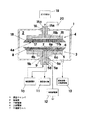
まず図1を参照してプラズマ処理装置について説明する。図1において、真空チャンバ1の内部はプラズマ処理を行う処理室2となっており、処理室2内部には、下部電極3および上部電極4が上下に対向して配設されている。下部電極3は電極体5を備えており、電極体5は下方に延出した支持部5aによって絶縁体9を介して真空チャンバ1に装着されている。電極体5の上面には、高熱伝導性材料より成る載置部6が装着されており、載置部6の上面にはシリコンを含む処理対象物である半導体ウェハ7が載置される。半導体ウェハ7は、回路形成面の裏側を機械研磨によって研磨された直後の状態であり、図2(a)に示すように半導体ウェハ7の回路形成面に貼着された保護シート7aを載置部6に当接させ、研磨加工面を上向きにした状態で載置される。
First, the plasma processing apparatus will be described with reference to FIG. In FIG. 1, the inside of a
載置部6には上面に開口する多数の吸着孔6aが設けられており、吸着孔6aは電極体5の支持部5a内を貫通して設けられた吸引路5dと連通している。吸引路5dは真空吸引部11と接続されており、載置部6の上面に半導体ウェハ7が載置された状態で真空吸引部11から真空吸引することにより、半導体ウェハ7は載置部6に真空吸着により保持される。電極体5や載置部6を有する下部電極3は、半導体ウェハ7を保持する保持手段となっている。
The
載置部6の内部には冷却用の冷媒流路6b,6cが設けられており、冷媒流路6b,6cは支持部5a内を貫通して設けられた管路5b,5cと連通している。管路5b,5cは冷媒循環部10と接続されており、冷媒循環部10を駆動することにより、冷媒流路6b,6c内を冷却水などの冷媒が循環し、これによりプラズマ処理時に発生した熱によって加熱された載置部6が冷却される。載置部6を冷却する目的は、半導体ウェハ7の回路形成面に貼着された樹脂製の保護シート7aがプラズマの熱で溶融してしまうのを防止するためである。
電極体5は高周波電源12と電気的に接続されている。また真空チャンバ1内の処理室2は、真空排気・大気開放部13と接続されている。真空排気・大気開放部13は、処理室2からの真空排気、および処理室2内の真空破壊時の大気開放を行う。
The
上部電極(対向電極)4は、接地部20に接地された電極体15を備えており、電極体15は上方に延出した支持部15aによって絶縁体16を介して真空チャンバ1に装着されている。電極体15の下面には絶縁体17が装着されており、絶縁体17には多数のガス噴出孔17aが空隙部15bと連通して設けられている。つまり下部電極3側に面している上部電極4の対向面4aには、プラズマ発生用ガスを供給するガス噴出孔17aが多
数形成されている。これらのガス噴出孔17aは電極体15に設けられた空隙部15bと連通しており、さらに空隙部15bは支持部15a内を貫通して設けられたガス供給路15cを介してガス供給部19と接続されている。なお絶縁体17としては、ガス噴出孔17aがランダムに形成された多孔質材でもよい。
The upper electrode (counter electrode) 4 includes an
ガス供給部19は、6フッ化硫黄(SF6)とヘリウム(He)を、1(SF6):1(He)から1(SF6):10(He)の範囲の体積比で混合した混合ガスをプラズマ発生用ガスとして供給する。6フッ化硫黄(SF6)とヘリウム(He)の混合比は、主にエッチングレート、エッチング面(研磨加工面)の目視品質によって決められる。6フッ化硫黄(SF6)の混合比が高い場合(1(SF6):1(He))は、エッチングレートは高いものの目視品質が低く、エッチング面が白濁化してくる。一方、混合比が低い場合(1(SF6):10(He))は、目視品質はエッチング面が鏡面となって高くなるが、エッチングレートは低くなる。
The
真空排気・大気開放部13を駆動して処理室2内を真空排気し、次いでガス供給部19を駆動することにより、上部電極4に装着された絶縁体17のガス噴出孔17aより下方に向けてプラズマ発生用ガスが噴出する。この状態で高周波電源12を駆動して下部電極3の電極体5に高周波電圧を印加することにより、上部電極4と下部電極3との間の空間にはプラズマ放電が発生する。そしてこのプラズマ放電により発生したプラズマによって、載置部6上に載置された半導体ウェハ7の上面のプラズマエッチング処理が行われる。
The
図1に示すように、下部電極3の載置部6の外縁部には絶縁体8が、また上部電極4の絶縁体17の外縁部には絶縁体18がそれぞれ外周方向に張り出した形態で装着されている。これらの絶縁体8,18により、上部電極4と下部電極3との間の空間にプラズマ放電を発生させる際に、上部電極4の側面と下部電極3の側面との間で発生する異常放電を抑制し、下部電極3の載置部6上でのプラズマを安定させるという効果を有する。
As shown in FIG. 1, an
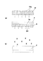
次にこのプラズマエッチング処理の過程を図2,図3を参照して説明する。図2(a)に示すように、保護シート7aに貼着された状態の半導体ウェハ7は下部電極3の載置部6上に載置され、真空吸着によって保持される。次いで処理室2内の真空排気を行った後、プラズマ発生用ガスがガス噴出孔17aから半導体ウェハ7の上面に対して吹き付けられる。この状態で高周波電源12を駆動して下部電極3と上部電極4との間に高周波電圧を印加することにより、半導体ウェハ7の上方の空間でプラズマ放電が発生する。
Next, the plasma etching process will be described with reference to FIGS. As shown in FIG. 2A, the semiconductor wafer 7 adhered to the
ここで、SF6を含む混合ガス中でプラズマ放電が発生することにより、図2(b)に示すように、ガス状のフッ素ラジカル(記号*で示す)が発生する。そしてこのフッ素ラジカルは、プラズマ発生ガス中のヘリウムガス(矢印参照)の流れによって半導体ウェハ7の表面に吹き付けられ、ここでフッ素ラジカルが半導体ウェハ7の成分であるSiに作用することにより、図3(a)に示すように、Siはガス状のSiF4(記号○で示す)となって半導体ウェハ7の表面から蒸散し、ヘリウムガスの流れによって除去される。
Here, when plasma discharge is generated in the mixed gas containing SF 6 , gaseous fluorine radicals (indicated by the symbol *) are generated as shown in FIG. The fluorine radicals are sprayed onto the surface of the
そしてこの反応と同時に反応生成物としてフッ素と硫黄の化合物SFn(記号●で示す)が発生するが、図3(b)に示すように、この反応生成物も同様に半導体ウェハ7の表面に吹き付けられるヘリウムガスの流れによって除去され、半導体ウェハ7の表面に残留して堆積することがない。
At the same time as this reaction, a fluorine and sulfur compound SFn (indicated by the symbol ●) is generated as a reaction product. This reaction product is sprayed on the surface of the
すなわち、本実施の形態に示すプラズマ処理においては、プラズマ発生用ガス中に含まれたヘリウムガスは、プラズマ放電によって発生したフッ素ラジカルを処理対象面である半導体ウェハ7のシリコン表面に吹き付けるとともに、フッ素ラジカルとSiとの反応によって生成したガス状のSiF4や、反応によって生成されるSFnを半導体ウェハ7の
表面から除去するキャリアガスとしての役割を果たしている。
That is, in the plasma processing shown in the present embodiment, helium gas contained in the plasma generating gas blows fluorine radicals generated by plasma discharge onto the silicon surface of the
これにより、Siの除去反応後においても半導体ウェハ7の処理対象面に残留して堆積しやすい反応生成物を確実に除去することができる。従って、このような反応生成物が処理対象面に残留することによる全体的なエッチングレートの低下や、反応生成物が処理表面で偏って残留することによるエッチング効果のばらつきが発生しない。
Thereby, even after the Si removal reaction, reaction products that remain on the processing target surface of the
このため、エッチング処理後の半導体ウェハ7の表面が、エッチング効果のばらつきによって白濁状外観を示す目視品質の低下が発生しない。またプラズマ発生用ガスとして、6フッ化硫黄(SF6)を用いることにより、従来の4フッ化炭素CF4を用いる場合と比較して、1分子あたりのフッ素原子数が多いことから、シリコン表面からSiを除去するエッチングレートを従来より向上させることができる。
For this reason, the surface of the
一方、ヘリウムガス(He)はキャリアガスとしての効果を持つ以外に、他のガス種に比べて非常に放電を開始するための放電開始最小電圧が低いことが知られている。つまり6フッ化硫黄(SF6)は放電開始最小電圧が高く、圧力が数百Pa以上の6フッ化硫黄のみでは平行平板電極に高周波電圧を印加しても電界の強い場所でのみ放電が起こり、エッチング分布がばらつく。そのため放電しやすいヘリウムガス(He)を混合することにより、低い高周波電圧または高周波電力でも均一性の高いエッチングを実現できる。 On the other hand, it is known that helium gas (He) has an effect as a carrier gas and has a very low minimum discharge start voltage for starting discharge compared to other gas types. In other words, sulfur hexafluoride (SF 6 ) has a high minimum discharge start voltage, and with only sulfur hexafluoride having a pressure of several hundred Pa or higher, discharge occurs only in a place where an electric field is strong even when a high frequency voltage is applied to the parallel plate electrodes. Etching distribution varies. Therefore, by mixing helium gas (He) that is easy to discharge, highly uniform etching can be realized even with a low high-frequency voltage or high-frequency power.
このプラズマ処理により、前工程の機械研磨によって加工面に発生したマイクロクラックを含むストレス層が効率よく除去される。そしてプラズマ処理後の半導体ウェハ7が、載置部6による真空吸着を解除された後に処理室2から搬出されることによりプラズマ処理を終了する。
By this plasma treatment, the stress layer including micro cracks generated on the processed surface by the mechanical polishing in the previous process is efficiently removed. Then, after the vacuum suction by the mounting
上記説明したように、シリコンを含む処理対象物である半導体ウェハのプラズマエッチングにおいて、プラズマ発生用ガスとして6フッ化硫黄とヘリウムとの混合ガスを用いることにより、4フッ化炭素をプラズマ発生用ガスとして用いる従来の方法よりエッチングレートを向上させることができる。また反応生成物がキャリアガスとしてのヘリウムガスによって処理表面から除去され、処理後の表面がエッチングのばらつきに起因する白濁状外観を呈することがなく、目視品質に優れたプラズマエッチング処理を高能率で行うことが可能となっている。 As described above, in plasma etching of a semiconductor wafer that is a processing target containing silicon, carbon tetrafluoride is converted into a plasma generating gas by using a mixed gas of sulfur hexafluoride and helium as a plasma generating gas. The etching rate can be improved as compared with the conventional method used as the above. In addition, the reaction product is removed from the processing surface by helium gas as a carrier gas, and the surface after processing does not show a cloudy appearance due to etching variation, and plasma etching processing with excellent visual quality is highly efficient. It is possible to do.
さらには、対向電極(上部電極4)の下部電極3側の対向面4aに多数形成されたガス噴出孔17aからプラズマ発生用ガスを供給するので、半導体ウェハ7の研磨加工面全体に満遍なくプラズマ発生用ガスを行きわたらせることができ、同時にSiF4やSFn等、反応によって発生したガスを研磨面から効率よく除去して、高いエッチングレートの処理を実現することができる。
Further, since the gas for generating plasma is supplied from a large number of
本発明によれば、シリコンを含む半導体ウェハのプラズマエッチング処理において、6フッ化硫黄とヘリウムとを含むプラズマ発生用ガスを用い、載置部に高周波電圧を印加し、この載置部に対向する位置に配置された対向電極の対向面からプラズマ発生用ガスを供給しながらプラズマ処理を行うようにしたので、ヘリウムガスをフッ素ラジカルや反応生成物のキャリアガスとして作用させ、反応生成物の再付着によるエッチングレートの低下およびエッチングのばらつきに起因する目視品質の低下を防止することができ、シリコンを含む半導体ウェハのプラズマ処理方法として有用である。 According to the present invention, in a plasma etching process of a semiconductor wafer containing silicon, a plasma generating gas containing sulfur hexafluoride and helium is used , a high frequency voltage is applied to the mounting portion, and the mounting portion is opposed to the mounting portion. Since the plasma treatment is performed while supplying the gas for generating the plasma from the opposing surface of the counter electrode arranged at the position , helium gas acts as a fluorine radical or a reaction product carrier gas to reattach the reaction product. It is possible to prevent a reduction in etching quality due to the etching rate and a reduction in visual quality due to etching variations, and it is useful as a plasma processing method for semiconductor wafers containing silicon.
1 真空チャンバ
2 処理室
3 下部電極
4 上部電極
7 半導体ウェハ
19 ガス供給部
DESCRIPTION OF
Claims (3)
前記載置部に高周波電圧を印加し、この載置部に対向する位置に配置された対向電極の対向面から前記プラズマ発生用ガスを供給しながらプラズマ処理を行うことを特徴とする半導体ウェハのプラズマ処理方法。 A plasma processing method for performing an etching process on the surface of a semiconductor wafer comprising silicon, said surface is polished surface polishing the back side of the circuit forming surface, the semiconductor wafer placing portion of the processing chamber for performing a plasma treatment And generating a plasma discharge in a state in which a plasma generating gas containing sulfur hexafluoride and helium is supplied from a gas ejection hole formed in the porous material in the processing chamber, microcracks that occur are those removed by etching,
A high-frequency voltage is applied to the mounting portion, and plasma processing is performed while supplying the plasma generating gas from a facing surface of a counter electrode disposed at a position facing the mounting portion . Plasma processing method.
Priority Applications (1)
| Application Number | Priority Date | Filing Date | Title |
|---|---|---|---|
| JP2004168196A JP4635478B2 (en) | 2004-06-07 | 2004-06-07 | Plasma processing method for semiconductor wafer |
Applications Claiming Priority (1)
| Application Number | Priority Date | Filing Date | Title |
|---|---|---|---|
| JP2004168196A JP4635478B2 (en) | 2004-06-07 | 2004-06-07 | Plasma processing method for semiconductor wafer |
Related Parent Applications (1)
| Application Number | Title | Priority Date | Filing Date |
|---|---|---|---|
| JP2001002196A Division JP3580255B2 (en) | 2001-01-10 | 2001-01-10 | Plasma processing method |
Publications (2)
| Publication Number | Publication Date |
|---|---|
| JP2004253820A JP2004253820A (en) | 2004-09-09 |
| JP4635478B2 true JP4635478B2 (en) | 2011-02-23 |
Family
ID=33028742
Family Applications (1)
| Application Number | Title | Priority Date | Filing Date |
|---|---|---|---|
| JP2004168196A Expired - Lifetime JP4635478B2 (en) | 2004-06-07 | 2004-06-07 | Plasma processing method for semiconductor wafer |
Country Status (1)
| Country | Link |
|---|---|
| JP (1) | JP4635478B2 (en) |
Family Cites Families (2)
| Publication number | Priority date | Publication date | Assignee | Title |
|---|---|---|---|---|
| JP3753194B2 (en) * | 1995-12-14 | 2006-03-08 | セイコーエプソン株式会社 | Plasma processing method and apparatus |
| JP2000150484A (en) * | 1998-11-11 | 2000-05-30 | Chemitoronics Co Ltd | Plasma etching device and etching method |
-
2004
- 2004-06-07 JP JP2004168196A patent/JP4635478B2/en not_active Expired - Lifetime
Also Published As
| Publication number | Publication date |
|---|---|
| JP2004253820A (en) | 2004-09-09 |
Similar Documents
| Publication | Publication Date | Title |
|---|---|---|
| JP3671854B2 (en) | Surface treatment method for silicon substrate | |
| TWI706460B (en) | Plasma etching method | |
| TWI553717B (en) | A focusing ring and a substrate processing device provided with the focusing ring | |
| KR20150098197A (en) | Etching method and plasma processing apparatus | |
| US6239036B1 (en) | Apparatus and method for plasma etching | |
| CN101920256A (en) | Method for reusing consumable parts for plasma processing equipment | |
| WO2002052628A1 (en) | Plasma processing method and plasma processor | |
| US20120108072A1 (en) | Showerhead configurations for plasma reactors | |
| US8342121B2 (en) | Plasma processing apparatus | |
| KR20070098499A (en) | Electrode plate and plasma processing device for plasma processing | |
| KR20050058464A (en) | Plasma processing method and plasma processing device | |
| JP2003224077A (en) | Plasma processing apparatus, electrode member, baffle plate manufacturing method, processing apparatus, and surface processing method | |
| KR100889433B1 (en) | Plasma processing apparatus | |
| JP2004319972A (en) | Etching method and etching apparatus | |
| JP4456218B2 (en) | Plasma processing equipment | |
| JP4635478B2 (en) | Plasma processing method for semiconductor wafer | |
| JP3580255B2 (en) | Plasma processing method | |
| KR20110006932A (en) | Board retainer | |
| JP5525319B2 (en) | Etching method and etching apparatus | |
| JP4231362B2 (en) | Plasma processing apparatus and plasma processing method | |
| US6867146B2 (en) | Plasma processing method | |
| JP2007027564A (en) | Surface treatment method and surface treatment apparatus | |
| KR101262904B1 (en) | Plasma etching apparatus | |
| JP2001068452A (en) | Apparatus and method for etching silicon substrate with circuit pattern formed | |
| KR100946385B1 (en) | IC high density semiconductor mold mold cleaning device |
Legal Events
| Date | Code | Title | Description |
|---|---|---|---|
| A621 | Written request for application examination |
Free format text: JAPANESE INTERMEDIATE CODE: A621 Effective date: 20071217 |
|
| RD01 | Notification of change of attorney |
Free format text: JAPANESE INTERMEDIATE CODE: A7421 Effective date: 20080115 |
|
| RD01 | Notification of change of attorney |
Free format text: JAPANESE INTERMEDIATE CODE: A7421 Effective date: 20091120 |
|
| A131 | Notification of reasons for refusal |
Free format text: JAPANESE INTERMEDIATE CODE: A131 Effective date: 20100831 |
|
| A521 | Request for written amendment filed |
Free format text: JAPANESE INTERMEDIATE CODE: A523 Effective date: 20101006 |
|
| TRDD | Decision of grant or rejection written | ||
| A01 | Written decision to grant a patent or to grant a registration (utility model) |
Free format text: JAPANESE INTERMEDIATE CODE: A01 Effective date: 20101026 |
|
| A01 | Written decision to grant a patent or to grant a registration (utility model) |
Free format text: JAPANESE INTERMEDIATE CODE: A01 |
|
| A61 | First payment of annual fees (during grant procedure) |
Free format text: JAPANESE INTERMEDIATE CODE: A61 Effective date: 20101108 |
|
| FPAY | Renewal fee payment (event date is renewal date of database) |
Free format text: PAYMENT UNTIL: 20131203 Year of fee payment: 3 |
|
| R151 | Written notification of patent or utility model registration |
Ref document number: 4635478 Country of ref document: JP Free format text: JAPANESE INTERMEDIATE CODE: R151 |
|
| FPAY | Renewal fee payment (event date is renewal date of database) |
Free format text: PAYMENT UNTIL: 20131203 Year of fee payment: 3 |
|
| EXPY | Cancellation because of completion of term |