JP4635476B2 - Image forming apparatus - Google Patents
Image forming apparatus Download PDFInfo
- Publication number
- JP4635476B2 JP4635476B2 JP2004159254A JP2004159254A JP4635476B2 JP 4635476 B2 JP4635476 B2 JP 4635476B2 JP 2004159254 A JP2004159254 A JP 2004159254A JP 2004159254 A JP2004159254 A JP 2004159254A JP 4635476 B2 JP4635476 B2 JP 4635476B2
- Authority
- JP
- Japan
- Prior art keywords
- image forming
- temperature
- forming apparatus
- unit
- atmosphere
- Prior art date
- Legal status (The legal status is an assumption and is not a legal conclusion. Google has not performed a legal analysis and makes no representation as to the accuracy of the status listed.)
- Expired - Fee Related
Links
Images


Landscapes
- Control Or Security For Electrophotography (AREA)
Description
この発明は、電子写真方式を適用した複写機、プリンタ、ファクシミリあるいはこれらの複合機等の画像形成装置に関するものである。 The present invention relates to an image forming apparatus such as a copying machine, a printer, a facsimile, or a complex machine to which an electrophotographic system is applied.
従来より、電子写真方式を適用した複写機、プリンタ、ファクシミリあるいはこれらの複合機等の画像形成装置では、光源から出力された光ビームにより走査露光される感光体を複数備え、カラー画像を形成する画像形成装置が知られている。このような画像形成装置を低温下に放置した後に、装置本体の周囲の温度を室内の空調設備等により急激に上昇させると、装置内の雰囲気の温度は低温から高温へと急激に上昇する。このとき装置内の各種部品の温度は、短時間では周囲環境の温度変動に追随しにくいため、このような急激な装置本体内の雰囲気の温度上昇が生じると、各種部品の表面には結露が発生する可能性があった。特に、レーザを備え、レーザからの光を走査して射出する光走査装置内の光学部品等に発生した結露は、感光体に走査露光される光ビームの光学特性の劣化を引き起こす場合がある。 2. Description of the Related Art Conventionally, an image forming apparatus such as a copying machine, a printer, a facsimile, or a complex machine using an electrophotographic method includes a plurality of photosensitive members that are scanned and exposed by a light beam output from a light source, and forms a color image. An image forming apparatus is known. When such an image forming apparatus is left at a low temperature and then the temperature around the apparatus body is rapidly increased by an air conditioner or the like in the room, the temperature of the atmosphere in the apparatus is rapidly increased from a low temperature to a high temperature. At this time, the temperatures of the various components in the device are unlikely to follow the temperature fluctuations of the surrounding environment in a short time, so if such a sudden increase in the temperature of the atmosphere in the device body occurs, condensation will form on the surfaces of the various components. Could occur. In particular, dew condensation that occurs in an optical component or the like in an optical scanning device that includes a laser and emits light emitted from the laser may cause deterioration of the optical characteristics of the light beam that is scanned and exposed on the photosensitive member.
このような問題を解決するために、光走査装置内の光学部品等の結露を抑制する技術が開示されている(例えば、特許文献1参照)。この技術によれば、半導体レーザや反射ミラーを含む光学部品を箱状の光学ユニット内におさめて、その内部を密封する。これによって、昇温した雰囲気が露点温度以下の光学部品に触れることを抑制することができ、半導体レーザ等を含む光学部品の結露を防止することができる。
しかしながら、特許文献1の技術を適用することによって、光走査装置内の光学部品に発生する結露を防止することはできるが、前述のように、光走査装置は、前記光学部品を密閉された筐体に収容しており、光ビームの射出開口には透明ガラス板を取付けている。このような構成では、透明ガラス板すなわち射出窓に結露が発生する可能性があるが、上記特許文献1では、射出窓の結露について言及されていない。 However, by applying the technique of Patent Document 1, it is possible to prevent dew condensation that occurs in the optical components in the optical scanning device. However, as described above, the optical scanning device includes a sealed casing in which the optical components are sealed. A transparent glass plate is attached to the light beam exit opening. In such a configuration, there is a possibility that condensation occurs on the transparent glass plate, that is, the exit window. However, in Patent Document 1, the condensation on the exit window is not mentioned.
ところで、射出窓に発生した結露は、通常であれば、画像形成装置内の雰囲気の自然流動によって除々に解消されると考えられるが、装置の小型化を図るために複数の感光体を上下方向に配列した画像形成装置においては、下方側に設けられた感光体に光ビームを照射する射出窓は、最上部の射出窓に比べて該射出窓付近の雰囲気が滞留しやすい画像形成装置の底部により近い位置に位置するために、射出窓上に発生した結露が解消されにくく、射出窓の結露対策は、重要な課題となる。 By the way, it is considered that the dew condensation generated in the exit window is normally gradually eliminated by the natural flow of the atmosphere in the image forming apparatus. However, in order to reduce the size of the apparatus, a plurality of photoconductors are arranged in the vertical direction. In the image forming apparatus arranged in the above, the exit window for irradiating the photosensitive member provided on the lower side with the light beam has a bottom portion of the image forming apparatus in which the atmosphere in the vicinity of the exit window tends to stay as compared with the uppermost exit window. Therefore, it is difficult to eliminate condensation that has occurred on the exit window, and countermeasures against condensation on the exit window are an important issue.
本発明は上記事実を考慮し、上下方向に配列された複数の感光体を備えた画像形成装置において、光ビームを感光体へ射出する射出窓への結露発生を防止する画像形成装置を得ることを目的とする。 In consideration of the above facts, the present invention provides an image forming apparatus that includes a plurality of photoconductors arranged in the vertical direction, and that prevents the formation of condensation on an exit window that emits a light beam to the photoconductor. With the goal.
本発明の画像形成装置は、筐体内に収納されると共に、装置本体設置面に対して上下方向に配列された複数の射出窓を介して画像データに応じた光ビームを射出する光ビーム走査ユニットと、前記複数の射出窓の各々に対応するように前記装置本体設置面に対して上下方向に配列され、前記光ビーム走査ユニットから射出された光ビームを受けて静電潜像が形成される複数の像担持体を備え、前記複数の像担持体上の静電潜像を現像し且つ記録媒体へ転写する画像形成ユニットと、加熱源、及び、前記画像形成ユニット側の壁面の前記複数の射出窓の配列方向の長さが前記光ビームを走査ユニット側の壁面の前記複数の射出窓の配列方向の長さより長いコ字型に断面が屈曲されると共に少なくとも装置上方側が開口とされ、且つ該コ字型に屈曲された内側に前記加熱源を有すると共に該加熱源によって加熱される雰囲気を均一に拡散する熱拡散板で構成され、前記光ビーム走査ユニットと前記画像形成ユニットとの間に設けられ、前記複数の射出窓における最下部から最上部へ流動するように装置本体内の雰囲気を加熱するヒータユニットと、前記加熱源のオンオフを制御する制御手段と、を有する画像形成装置である。 An image forming apparatus according to the present invention is housed in a housing and emits a light beam corresponding to image data through a plurality of exit windows arranged in a vertical direction with respect to the apparatus main body installation surface. And an electrostatic latent image is formed by receiving the light beam emitted from the light beam scanning unit so as to correspond to each of the plurality of emission windows. An image forming unit that includes a plurality of image carriers, develops electrostatic latent images on the plurality of image carriers and transfers them to a recording medium, a heating source, and the plurality of wall surfaces on the image forming unit side. The cross-section is bent into a U-shape in which the length in the arrangement direction of the exit windows is longer than the length in the arrangement direction of the plurality of exit windows on the wall surface on the scanning unit side, and at least the upper side of the apparatus is opened. Bent to the U-shape Consists of the thermal diffusion plate for uniformly diffusing the atmosphere is heated by the pressurized heat source which has the heating source on the inside, which is provided between the image forming unit and the light beam scanning unit, the plurality of An image forming apparatus comprising: a heater unit that heats an atmosphere in the apparatus main body so as to flow from the lowermost part to the uppermost part of the emission window; and a control unit that controls on / off of the heating source .
本発明の画像形成装置は、画像データに応じた光ビームを射出する光ビーム走査ユニットを備えている。光ビーム走査ユニットは、筐体内に収納されており、装置本体設置面に対して上下方向に配列された複数の射出窓各々を介して光ビームを画像形成ユニットへ射出する。画像形成ユニットは、複数の射出窓各々に対応するように、装置本体設置面に対して上下方向に配列された複数の像担持体を備えている。光ビーム走査ユニットから複数の射出窓各々を介して光ビームが射出されると、画像形成ユニットの対応する像担持体各々へ静電潜像が形成される。画像形成ユニットは、更に、複数の像担持体上に形成された静電潜像を現像して、記録媒体に転写する。 The image forming apparatus of the present invention includes a light beam scanning unit that emits a light beam corresponding to image data. The light beam scanning unit is housed in a housing, and emits a light beam to the image forming unit through each of a plurality of emission windows arranged in the vertical direction with respect to the apparatus main body installation surface. The image forming unit includes a plurality of image carriers arranged in the vertical direction with respect to the apparatus main body installation surface so as to correspond to each of the plurality of exit windows. When a light beam is emitted from the light beam scanning unit through each of the plurality of emission windows, an electrostatic latent image is formed on each corresponding image carrier of the image forming unit. The image forming unit further develops the electrostatic latent images formed on the plurality of image carriers and transfers them to a recording medium.
ヒータユニットは、光ビーム走査ユニットと画像形成ユニットとの間に設けられており、光ビーム走査ユニットと画像形成ユニットとの間の雰囲気を加熱する。ヒータユニットによって雰囲気が加熱されると、加熱された雰囲気は、光ビーム走査ユニットと画像形成ユニットとの間を上昇する。この加熱された雰囲気の上昇によって、最下部に位置する射出窓から最上部へ位置する射出窓方向へと、光ビーム走査装置と画像形成ユニット間の雰囲気が流動し、装置本体内が暖められる。 The heater unit is provided between the light beam scanning unit and the image forming unit, and heats the atmosphere between the light beam scanning unit and the image forming unit. When the atmosphere is heated by the heater unit, the heated atmosphere rises between the light beam scanning unit and the image forming unit. Due to the rise in the heated atmosphere, the atmosphere between the light beam scanning device and the image forming unit flows from the exit window located at the bottom to the exit window located at the top, and the inside of the apparatus main body is warmed.
このため、装置本体内の底部の雰囲気の澱みが解消されるとともに、ヒータユニットによって加熱された雰囲気を最下部から最上部の射出窓へと流動させることができるので、複数の射出窓を加熱された雰囲気によって暖めることができる。 This eliminates the stagnation of the atmosphere at the bottom of the main body of the apparatus and allows the atmosphere heated by the heater unit to flow from the lowermost part to the uppermost injection window. It can be warmed by the atmosphere.
従って、装置本体の外部の気温の急激な上昇に伴って装置本体内の雰囲気の温度が急上昇しても、複数の射出窓は、ヒータユニットによって加熱された雰囲気により既に暖められた状態にあるので、装置本体内の昇温した雰囲気が露点温度以下の射出窓に触れることを抑制することができ、射出窓への結露の発生を抑制することができる。 Therefore, even if the temperature of the atmosphere inside the apparatus main body suddenly rises due to a rapid rise in the temperature outside the apparatus main body, the plurality of exit windows are already heated by the atmosphere heated by the heater unit. In addition, it is possible to suppress the heated atmosphere in the apparatus main body from touching the exit window having the dew point temperature or less, and to suppress the occurrence of condensation on the exit window.
前記ヒータユニットの少なくとも加熱された雰囲気の出口が、最下部に位置する射出窓の更に下方側に設けることができる。 An outlet for at least a heated atmosphere of the heater unit may be provided further below the exit window located at the lowermost part.
ヒータユニットの少なくとも加熱された雰囲気の出口を、最下部に位置する射出窓の更に下方側に設けることができるので、ヒータユニットによって加熱された雰囲気は、最下部に位置する射出窓の更に下方側から装置上方側へと上昇する。このため、最下部の射出窓から最上部の射出窓へと加熱された雰囲気を流動させることができ、効率よく複数の射出窓を暖めることができる。従って、複数の射出窓の結露を防止することができる。 Since at least the outlet of the heated atmosphere of the heater unit can be provided further below the exit window located at the lowermost part, the atmosphere heated by the heater unit is further below the exit window located at the lowermost part. Ascend to the upper side of the device. For this reason, the heated atmosphere can flow from the lowermost exit window to the uppermost exit window, and the plurality of exit windows can be efficiently warmed. Therefore, dew condensation on the plurality of exit windows can be prevented.
前記ヒータユニットが、加熱源と、前記画像形成ユニット側の壁面の前記複数の射出窓の配列方向の長さが前記光ビーム走査ユニット側の壁面の前記複数の射出窓の配列方向の長さより長いコ字型に断面が屈曲されると共に少なくとも装置上方側が開口とされ前記加熱源によって加熱される雰囲気を均一に拡散する熱拡散板とで構成することができる。 In the heater unit, the length in the arrangement direction of the plurality of exit windows on the wall surface on the image forming unit side is longer than the length in the arrangement direction of the plurality of exit windows on the wall surface on the light beam scanning unit side. The cross section is bent into a U-shape, and at least the upper side of the apparatus is opened, and the heat diffusion plate can be configured to uniformly diffuse the atmosphere heated by the heating source.
ヒータユニットは、加熱源と熱拡散板とで構成される。加熱源によって加熱された雰囲気は、熱拡散板によって均一に拡散されるとともに、コ字型に屈曲された熱拡散板の内側から、該熱拡散板の装置上方側の開口を介して上昇するので、効率よく最下部の射出窓から最上部の射出窓へと、加熱された雰囲気を流動させることができる。 The heater unit is Ru is composed of a heat source and a heat diffusion plate. The atmosphere heated by the heating source is uniformly diffused by the heat diffusing plate and rises from the inside of the heat diffusing plate bent in a U-shape through the opening on the upper side of the heat diffusing plate. The heated atmosphere can be efficiently flowed from the lowermost exit window to the uppermost exit window.
前記制御手段は、前記加熱源への電源線に設けられ、少なくとも装置本体内の温度が第1の温度以下のときに作動して前記加熱源をオンすると共に、前記第1の温度より高い第2の温度以上のときに作動して前記加熱源をオフするサーモスタットとすることができる。 The control means is provided in a power supply line to the heating source, operates at least when the temperature in the apparatus main body is equal to or lower than the first temperature, turns on the heating source, and is higher than the first temperature. It can be set as the thermostat which act | operates when it is more than 2 temperature, and turns off the said heating source.
サーモスタットは、電源線を介して加熱源に接続されており、少なくとも装置本体内の温度が第1の温度以下となると、加熱源をオンする。第1の温度を、低温時、(例えば5℃を想定)複数の射出窓の温度を装置本体内の雰囲気の露点温度に下降しないよう、事前に加熱源をオンすることができる。このため、複数の射出窓の表面温度が、温度上昇後の雰囲気の露点温度以下となることを抑制することができ、射出窓への結露発生を抑制することができる。また、サーモスタットは、第1の温度より高い第2の温度以上のときに作動して加熱源をオフすることができるので、画像形成装置内の温度が上昇し続けることを抑制することができる。 The thermostat is connected to a heating source via a power line, and turns on the heating source at least when the temperature inside the apparatus main body is equal to or lower than the first temperature. When the first temperature is low, the heating source can be turned on in advance so that the temperature of the plurality of exit windows does not drop to the dew point temperature of the atmosphere in the apparatus main body (for example, assuming 5 ° C.). For this reason, it can suppress that the surface temperature of a some injection window becomes below the dew point temperature of the atmosphere after temperature rise, and can suppress the dew condensation generation | occurrence | production to an injection window. In addition, the thermostat can operate when the temperature is equal to or higher than the second temperature higher than the first temperature and can turn off the heating source, so that the temperature inside the image forming apparatus can be prevented from continuing to rise.
前記第1の温度は、装置本体の稼働待機中の所定温度であり、前記第2の温度は、装置本体の稼働待機中または稼働中の所定温度とすることができる。 The first temperature may be a predetermined temperature during operation standby of the apparatus main body, and the second temperature may be a predetermined temperature during operation standby of the apparatus main body or during operation.
サーモスタットが、加熱源をオンする温度を画像形成装置の動作停止中及び動作待機中等の稼働停止中の所定温度とし、加熱源をオンする温度を画像形成装置の稼働中の所定温度とすることができるので、画像形成装置の稼働中から稼働待機中の温度範囲内となるように、サーモスタットをオンオフすることができる。
装置本体内の湿度を検知する湿度センサと、前記複数の射出窓の各々の表面温度を測定する温度センサと、前記湿度センサで検知された装置本体内の湿度及び前記温度センサによって検知された温度に基づいて、結露する低温高湿が検知されたときに、前記加熱源をオンするように制御する制御部と、を更に備えた構成とすることができる。
The thermostat may set the temperature at which the heat source is turned on to a predetermined temperature during operation stop of the image forming apparatus such as when the operation of the image forming apparatus is stopped or waiting for operation, and the temperature at which the heat source is turned on is set to the predetermined temperature during operation of the image forming apparatus. Therefore, the thermostat can be turned on / off so that the temperature is within the temperature range of the image forming apparatus during operation to standby.
A humidity sensor for detecting the humidity in the apparatus body, a temperature sensor for measuring the surface temperature of each of the plurality of exit windows, the humidity in the apparatus body detected by the humidity sensor and the temperature detected by the temperature sensor And a controller that controls to turn on the heating source when dew condensation is detected at low temperature and high humidity.
以上説明した如く本発明では、ヒータユニットを、光ビーム走査ユニットと画像形成ユニットとの間に設けて、光ビーム走査ユニットと画像形成ユニット間の雰囲気を加熱して、装置本体設置面に対して上下方向に配列された複数の射出窓の最下部から最上部へ加熱された雰囲気を流動させるので、複数の射出窓を加熱された雰囲気により暖めることができるので、複数の射出窓への結露の発生を抑制することができる、という効果を有する。 As described above, in the present invention, the heater unit is provided between the light beam scanning unit and the image forming unit, and the atmosphere between the light beam scanning unit and the image forming unit is heated to Since the heated atmosphere flows from the bottom to the top of the plurality of exit windows arranged in the vertical direction, the plurality of exit windows can be heated by the heated atmosphere, so that condensation on the plurality of exit windows is prevented. It has the effect that generation | occurrence | production can be suppressed.
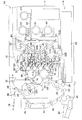
図1に示すように、本発明の実施の形態に係る画像形成装置10には、エンジン部12が備えられており、エンジン部12の下部には、給紙ユニット14が設けられている。
As shown in FIG. 1, the
この給紙ユニット14は、用紙が積載される用紙トレイ22と、この用紙トレイ22から用紙を送り出す給紙ロール24と、で構成されており、給紙ロール24により送り出された用紙は、搬送ロール26、28を経て給紙路30を通過し、後述する転写ロール74へ搬送される。
The
この転写ロール74によってトナー像が用紙に転写され、定着部32の定着ロール32Aで定着された後、切替爪34の位置選択によって、排出ロール36又は排出ロール38により、エンジン部12の上部に設けられた第1の排出トレイ16又は第2の排出トレイ18へ排出される。
After the toner image is transferred onto the paper by the
ここで、両面印刷の場合、上記のような順序で表面の印刷が終わった後、第1の排出トレイ16へ用紙が完全に排出される前に、排出ロール36が逆転し、該用紙が反転路40へ供給される。そして、搬送ロール42、44、46、48を経て再び給紙路30に戻され、用紙の裏面側が印刷される。また、手差し印刷の場合、手差しトレイ20へ用紙を載置することで、用紙は手差しロール49から搬送ロール48を経て給紙路30へ搬送され、印刷される。
Here, in the case of double-sided printing, after the printing of the front surface is completed in the order as described above, before the paper is completely discharged to the
ところで、画像形成装置10の図1右側には、各色毎の現像剤(トナーと磁性キャリアからなる)が充填された4個の現像剤カートリッジ64が配設されている。この現像剤カートリッジ64は、それぞれ現像剤供給路65によって、図1の上から順に配列された後述する現像器60Y、60M、60K、60Cと接続されており、現像剤カートリッジ64中の現像剤が現像器60Y、60M、60K、60Cへ供給される。
Meanwhile, on the right side of FIG. 1 of the
現像剤カートリッジ64の図1左側には、露光ユニット62が配置されており、露光ユニット62からは、画像信号に応じた4本のレーザ光L(Y)、L(M)、L(K)、L(C)が、各々透明部材で構成され、画像形成装置10の設置面に対して上下方向に配列された射出窓204Y、204M、204K、204Cを介して、露光ユニット62の図1左側に配置された感光体ユニット50を構成する感光体ドラム52Y、52M、52K、52C各々へ向けて発せられ、感光体ドラム52Y、52M、52K、及び52C各々に潜像を形成するようになっている。
An
感光体ユニット50は、画像形成装置10の設置面に対して上下方向に並べられた4つの感光体ドラム52(52Y、52M、52K、52C)を備えており、上部から例えばイエロー(52Y)、マゼンダ(52M)、ブラック(52K)、シアン(52C)用となっている。
The photoconductor unit 50 includes four photoconductor drums 52 (52Y, 52M, 52K, and 52C) arranged in the vertical direction with respect to the installation surface of the
露光ユニット62は、 Y、M、C、K各色のレーザ光L(Y)、L(M)、L(K)、L(C)(以下総称する場合は、レーザ光Lという)を出力する光源部と、レーザ光Lに対して変調及び走査を行なう変調処理部と、露光面上の走査速度を補正するfθレンズや走査方向にレンズパワーを持つ面倒れ補正用のシリンドリカルレンズ等により構成された光学系と、を含んで構成されている。露光ユニット62は、光ビームを噴射するための上下方向に配列された射出窓204Y、204M、204K、及び204Cが設けられた箱状の筐体202を備えており、上記光源部、変調処理部、及び光学系は、筐体202内に設けられている。なお、噴出窓204Y、204M、204K、及び204Cは、その符号順に画像形成装置10の上方向から順に一列に配列されている。このように、光源部、変調処理部、及び光学系を筐体202内に設けることで、各種光走査装置へのホコリの付着を抑制することができる構成となっている。
The
露光ユニット62では、光源部から射出された各色のレーザ光Lが変調処理部に入射され、各色毎の画像情報に応じてそれぞれ変調されて、ポリゴンモータ63により回転するポリゴンミラー67により走査(主走査)される。ポリゴンミラー67により走査された各色のレーザ光Lは、ミラー群69により各色に対応する感光体ドラム52の配設方向に反射されて各感光体ドラム52上に結像される。
In the
感光体ユニット50には、各感光体ドラム52に対応して、帯電ロール56及びリフレッシュロール54が備えられており、それぞれ感光体ドラム52に接触回転するように設けられている。帯電ロール56では、感光体ドラム52を一様に帯電させ、後述する現像器ユニット58に備えられたマグネットロール80から飛翔するトナーを感光体ドラム52の表面に付着させる。一方、リフレッシュロール54では感光体ドラム52を放電させ、感光体ドラム52の表面に付着した残留トナーを取り除き、感光体ドラム52の表面にトナーが残留することで生じるゴースト等を防止する。
The photosensitive unit 50 is provided with a charging
ここで、現像器ユニット58は、それぞれの感光体ユニット50の図1右下側に配置されており、各感光体ドラム52(52Y、52M、52K、52C)に対応して4つの現像器60(60Y、60M、60K、60C)が上下方向に並べられている。
Here, the developing
この現像器60は、トリクル現像方式(現像剤の帯電性能の低下を防止して現像剤交換のインターバルを延ばすために、現像器内に現像剤を徐々に補給する一方で、過剰になった(劣化したキャリアを多く含む)劣化現像剤を排出しながら現像を行う現像方式である)を採用しており、劣化現像剤は図示しない回収容器に回収されるようになっている。 The developing device 60 is in a trickle developing system (in order to prevent the charging performance of the developer from being lowered and to extend the interval for changing the developer, the developer is gradually replenished in the developing device, but becomes excessive ( This is a developing system in which development is performed while discharging a deteriorated developer (which contains a lot of deteriorated carriers), and the deteriorated developer is collected in a collection container (not shown).
一方、感光体ユニット50の図1左側には、中間転写ユニット66が配置されており、3つのドラム状の中間転写体68、70、72が備えられている。2つの第1中間転写体68、70は、上下方向に上下に並べられており、上部の第1中間転写体68が、感光体ドラム52のうち上部に配置された2つの感光体ドラム52Y、52Mに接触回転し、下部の第1中間転写体70が、下部に配置された2つの感光体ドラム52K、52Cに接触回転するようになっている。また、第2中間転写体72は、第1中間転写体68、70の双方に接触回転するようになっており、この第2中間転写体72に、前述した転写ロール74が接触回転する。
On the other hand, an
したがって、感光体ドラム52Y、52Mから各トナー像が第1中間転写体68に転写され、感光体ドラム52K、52Cから各トナー像が第1中間転写体70にそれぞれ転写される。この第1中間転写体68、70に転写された各2色のトナー像が、第2中間転写体72に転写されて4色となり、この4色のトナー像が転写ロール74により用紙に転写されることになる。
Accordingly, the toner images are transferred from the
これらの中間転写体68、70、72の近傍には、それぞれクリーニングロール76及びクリーニングブラシ78が配置されており、中間転写体68、70、72の表面の残留トナーが掻き落とされる。
A cleaning
図2に示すように、現像器ユニット58は4つの現像器60で構成されており、各現像器60は箱状のハウジング110及びハウジング110を閉塞する蓋体120を備えており、ハウジング110には、感光体ドラム52へトナーを供給するマグネットロール80(現像剤担持体)と、現像器60内の現像剤を攪拌しマグネットロール80へ現像剤を供給するスパイラルオーガ112(供給部材)及びスパイラルオーガ114(攪拌部材)、が回転自在に軸支されている。
As shown in FIG. 2, the developing
また、各現像器60は、マグネットロール80が感光体ドラム52に当接する位置と、感光体ドラム52から退避した位置とに移動可能となっており、画像形成時には、マグネットロール80が感光体ドラム52に当接するようになっている。これにより、感光体ドラム52に形成された潜像に対応してトナーが感光体ドラム52に付着するようにしているが、画像形成が行われない場合には、現像器ユニット58は感光体ドラム52から退避するようになっている。
Each developing device 60 can move between a position where the
マグネットロール80には、交流成分に直流成分を重畳した現像バイアス電圧が印加されており、これにより感光体ドラム52の静電潜像(画像部)のみにトナーを静電的に付着させてトナー像の形成が行われる。
A developing bias voltage in which a DC component is superimposed on an AC component is applied to the
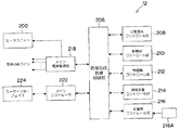
図3に示すように、エンジン部12は、メインコントローラ222を備えている。メインコントローラ222には、ユーザーインターフェイス224が接続され、ユーザーの操作によって画像形成等に関する指示がなされると共に、画像形成時の情報等をユーザーへ報知するようになっている。また、このメインコントローラ222には、図示しない外部ホストコンピュータとのネットワークラインが接続されており、画像データが入力されるようになっている。
As shown in FIG. 3, the
画像データが入力されると、メインコントローラ222では、例えば、画像データに含まれるプリント指示情報と、イメージデータとを解析し、エンジン部12に適合する形式(例えば、ビットマップデータ)に変換し、画像形成処理制御部206へ画像データを送出する。
When the image data is input, the
画像形成処理制御部206では、入力されたイメージデータに基づいて、光走査系コントロール部208、駆動系コントロール部210、帯電器コントロール部212、現像装置コントロール部214、定着器コントロール部216のそれぞれを同期制御し、画像形成を実行する。
The image formation
また、画像形成処理制御部206には、メイン電源管理部218が接続されている。メイン電源管理部218には、図示しない商用電源が接続されており、低電圧電源及び高電圧電源を生成し、電源供給ラインを介して、詳細を後述するヒータユニット200を含む画像形成装置10内の各部へ電源を供給する。
A main
ここで、画像形成装置10が設置された室内の温湿度が、空調設備の稼働等によって急激に上昇すると、室内の温度の上昇に伴って画像形成装置10内の雰囲気の温湿度もまた急激に上昇する。しかし、このとき画像形成装置10内の各種部品は、短時間では周囲の温度変動に追従しにくいため、各部品付近の昇温した雰囲気が該雰囲気の露点温度以下の部品表面触れることによって、各部品表面が結露する。画像形成装置10内の雰囲気が画像形成装置10内で自然に効率よく流動するのであれば、発生した結露は除々に解消されると考えられるが、画像形成装置10の底部の雰囲気は上部に比べて滞留しやすいため、雰囲気が滞留する下方に設けられた部品に発生した結露ほど解消されにくいという問題がある。特に、射出窓204Y、204M、204K、204Cに発生した結露は、射出窓204Y、204M、204K、204Cを介して感光体ドラム52Y、52M、52K、52C上に走査される光ビームの光学特性の劣化を引き起こす恐れがあり、下方に位置する射出窓204Cほど、最上部に位置する射出窓204Yに比べて発生した結露が解消されにくいという問題があった。
Here, when the temperature and humidity in the room in which the
図4に示すように、例えば、画像形成装置10内の初期湿度65%であり、且つ画像形成装置10内の雰囲気が0℃から8℃であって、各射出窓204Y、204M、204K、204C各々の表面温度が0℃〜8℃であるときに、画像形成装置10外の温度変動に伴って画像形成装置10内の雰囲気の温湿度が急激に17℃、70%に上昇すると、各射出窓204Y、204M、204K、204C各々上には結露が発生する。これは、湿度70%で且つ温度17℃の雰囲気が、該雰囲気の露点温度である12℃より低い温度の射出窓204Y、204M、204K、204C各々の表面に触れる事によって、該雰囲気の飽和水蒸気量が減り結果として水滴が各射出窓の表面に発生するためである。
As shown in FIG. 4, for example, the initial humidity in the
一方、画像形成装置10内の湿度が65%から70%に変化し、且つ各射出窓204Y、204M、204K、204C各々の表面温度が12℃以上であるときに、画像形成装置10外の温湿度変動に伴って画像形成装置10内の雰囲気の温湿度が急激に17℃、70%に上昇しても、各射出窓204Y、204M、204K、204C各々には結露は発生しない。これは、湿度70%で且つ17℃の雰囲気が該雰囲気の露点温度である12℃より高い温度の射出窓204Y、204M、204K、204C各々の表面に触れるためである。
On the other hand, when the humidity in the
すなわち、画像形成装置10内の温湿度上昇前における、各射出窓204Y、204M、204K、204C各々の表面温度が、急激な温度上昇後の画像形成装置10内の雰囲気の露点温度以上であれば、各射出窓204Y、204M、204K、204C上に結露は発生しない。
That is, if the surface temperature of each of the
そこで、本実施の形態の画像形成装置10は、図1に示すように、本発明のヒータユニットとしてのヒータユニット200を備えている。ヒータユニット200は、上下方向に配列された複数の感光体ドラム52を含む、本発明の画像形成ユニットとしての感光体ユニット50と、本発明の光ビーム走査ユニットとしての露光ユニット62との間で、且つ画像形成装置10の底部に設けられており、加熱源としてのヒータ220、及びサーモスタット226を含んで構成されている。
Therefore, the
ヒータユニット200を感光体ユニット50と露光ユニット62との間で且つ画像形成装置10の底部に設けたので、ヒータ220によって加熱された雰囲気は、該ヒータユニット200の設置位置である露光部62と感光体ユニット50との間の画像形成装置10の底部から、上方向へと上昇する。このため、ヒータ220によって加熱された雰囲気は、最下部に位置する射出窓204Cから最上部に位置する射出窓204方向に流動し、更に画像形成装置10内を流動する。
Since the
図5に示すように、ヒータユニット200は、断面が略コ字型に屈曲されると共に、開口面が上方向とされた熱拡散板228の内側に、ヒータ220及びサーモスタット226を設けた構成となっている。熱拡散板228の感光体ユニット50側の壁面228Aの上下方向の長さは、露光ユニット62側の壁面228Bの上下方向の長さより長くなっている。このように、熱拡散板228の形状は、略コ字型に屈折されると共に開口面を上方向とされているので、ヒータ220によって加熱された雰囲気が左右方向、すなわち、画像形成装置10の底部の露光部62及び感光体ユニット50方向へ分散することを抑制することができる。
As shown in FIG. 5, the
図6に示すように、メイン電源管理部218は、サーモスタット226を介して、ヒータ220の入力端子に接続されており、ヒータ220の出力端子は、メイン電源管理部218に接続されている。
As shown in FIG. 6, the main
本実施の形態では、画像形成装置10内の初期温湿度は室温5℃で且つ湿度65%であるものとし、温湿度上昇後の画像形成装置10内の雰囲気は17℃で且つ湿度70%であるとものして説明する。また、室内の温湿度が5℃、65%から17℃、70%に変化した場合、露点温度は12℃以下であるので、画像形成装置10内の雰囲気の上昇後に、温度上昇した雰囲気が12℃以下(露点温度以下)の射出窓204Y、204M、204K、204Cに触れて結露することを防ぐために、本実施の形態では、サーモスタット226は、画像形成装置10内の温度が8℃以下のときにヒータ220をオンするものとする。また、本実施の形態の画像形成装置10の稼働待機または稼働中のヒーター温度は50℃以下であるものとして説明する。本実施の形態では、画像形成装置10の稼働中の温度以上に画像形成装置10内の雰囲気の温度が上昇することを防ぐために、サーモスタット226は、画像形成装置10内の温度が50℃以上のときに作動して、ヒータ220をオフする。
In the present embodiment, the initial temperature and humidity in the
以下に本実施の形態の作用を説明する。 The operation of this embodiment will be described below.
(画像形成処理の流れ)
各感光体ドラム52の周囲では、周知の電子写真方式による各色毎の画像形成(印字)プロセスが次のように行われる。
(Flow of image forming process)
Around each
まず、各感光体ドラム52は所定の回転速度(例えば95mm/sec)で回転駆動される。
First, each
そして、感光体ドラム52の表面は、図1に示すように、帯電ロール56に所定の帯電レベル(例えば、約−800V)の直流電圧を印加することによって、所定レベルに一様に帯電される。なお、本実施の形態では、帯電ロール56に対して直流電圧のみを印加しているが、交流成分を直流成分に重畳するように構成することもできる。
As shown in FIG. 1, the surface of the
次に、一様な表面電位とされた各感光体ドラム52各々の表面に、露光ユニット62によって各色に対応したレーザ光Lが、複数の射出窓204Y、204M、204K、204C各々を介して照射されて、各色毎の画像情報に応じた静電潜像が形成される。これにより、感光体ドラム52のレーザ光Lによる露光部位の表面電位は所定レベル(例えば、−60V以下程度)にまで除電される。
Next, the laser light L corresponding to each color is irradiated by the
そして、各感光体ドラム52の表面に形成された静電潜像は対応する各現像器ユニット58によって現像され、各感光体ドラム52上に各色のトナー像として可視化される。
The electrostatic latent image formed on the surface of each
次に、各感光体ドラム52上に形成された各色のトナー像は、対応する一次中間転写ドラム68、70上に静電的に一次転写される。ここで、感光体ドラム52Y、52Mに形成されたY色及びM色のトナー像は一次中間転写ドラム68に、感光体ドラム52K、52Cに形成されたK色及びC色のトナー像は一次中間転写ドラム70上に、各々転写される。
Next, the toner images of the respective colors formed on the respective
この後、一次中間転写ドラム68、70上に形成されたトナー像は、二次中間転写ドラム72上に静電的に二次転写される。これにより、二次中間転写ドラム72上には、単色像からY、M、K、Cの各色の四重色像までのトナー像が形成されることになる。
Thereafter, the toner image formed on the primary intermediate transfer drums 68 and 70 is electrostatically secondary-transferred onto the secondary
最後に、二次中間転写ドラム72上に形成されたトナー像は、転写ロール74によって用紙搬送路を通る用紙に三次転写される。当該用紙は、三次転写の後、用紙上に形成されたトナー像が、定着ユニット32によって加熱定着され、画像形成プロセスが終了する。
Finally, the toner image formed on the secondary
(画像形成装置内の雰囲気の温度調整)
以下、図7のタイムチャートに従い、本実施の形態の画像形成装置10内における雰囲気の温度調整について説明する。
(Adjusting the temperature of the atmosphere in the image forming device)
Hereinafter, the temperature adjustment of the atmosphere in the
本実施の形態では、室内に画像形成装置10を設置するものとし、該室内に予め設置された暖房がオンとなると、室内の温湿度が17℃、70%に上昇し、暖房がオフとなると、温湿度が5℃、65%に下降する室内に、画像形成装置10を設置した場合を想定して説明する。なお、画像形成装置10内の雰囲気の温度は、画像形成装置10が設置された室内の温度が17℃に上昇すると、画像形成装置10の稼働待機及び稼働中では17℃に向かって上昇するものとして説明する。また、画像形成装置10内の湿度は、温度上昇前後において65%から上昇するものとして説明する。
In the present embodiment, it is assumed that the
ユーザの退社時(午後10時)に暖房がオフとなると(矢印A参照)、画像形成装置10内の気温は除々に画像形成装置10外の気温と同一の5℃に向かって下降を始め、3時間程度経過したときに、画像形成装置10内の気温は、8℃以下となる(図7の矢印B参照)。画像形成装置10内の気温が8℃に下降すると、ヒータ220が、サーモスタット226の作動によってオンとなる(図7の矢印C参照)。
When heating is turned off when the user leaves the office (10:00 pm) (see arrow A), the temperature inside the
ヒータ220がオンすると、ヒータ220によって加熱された雰囲気が、コ字型に屈曲された熱拡散板228の内側から熱拡散板228の上方向の開口部を介して上昇する。そして、加熱された雰囲気は、最下部に位置する射出窓204Cから最上部に位置する射出窓204Y方向へ向かって上昇する。このように、加熱された雰囲気が、最下部に位置する射出窓204Cから最上部に位置する射出窓204Y方向へ向かって上昇して、画像形成装置10内を流動するので、画像形成装置10の底部の雰囲気の滞留を抑制することができる。また、最下部に位置する射出窓204Cから最上部に位置する射出窓204Yを介して画像形成装置10内をヒータ220によって加熱された雰囲気が流動するので、画像形成装置10内は暖められた状態で保持される(矢印D参照)。従って、射出窓204Y、204M、204K、204Cもまた、ヒータ220によって加熱された雰囲気によって、8℃以上に暖められた状態で保持される。
When the
更に、翌朝午前8時に、ユーザによって暖房がオンされて、室温が17℃へと上昇すると、画像形成装置10内の気温もまた上昇し始める(矢印E参照)。画像形成装置10内の温度が50℃となると(矢印G参照)、サーモスタット226の作動によってヒータ220はオフとなる(矢印H参照)。
Further, when the user turns on heating at 8 am the next morning and the room temperature rises to 17 ° C., the temperature in the
このように、温度上昇後の画像形成装置10内の雰囲気の露点温度近くまで、画像形成装置10内の雰囲気の温度が低下すると、ヒータ220がオンとなりヒータ220により加熱された雰囲気が、感光体ユニット50と露光ユニット62間の最下部に位置する射出窓204Cから最上部に位置する射出窓204Y方向へ向かって上昇し、画像形成装置10内を流動する。このため、感光体ユニット50と露光ユニット62間の底部の雰囲気の澱みを解消することができるとともに、画像形成装置10内の雰囲気の急激な上昇前に、射出窓204Y、204M、204K、204Cを温度上昇後の雰囲気の露点温度以上となるように暖めることができるので、画像形成装置10内の昇温した雰囲気が、該雰囲気の露点温度以下の射出窓204Y、204M、204K、204Cに触れることを抑制することができる。従って、射出窓204Y、204M、204K、204Cへの結露の発生を抑制することができる。
As described above, when the temperature of the atmosphere in the
以上説明したように、本実施の形態の画像形成装置10によれば、上下方向に配列された複数の感光体ドラム52を含む感光体ユニット50と露光ユニット62との間の、画像形成装置10の底部に、ヒータ220を備えたヒータユニット200を設けた。このため、ヒータ220によって加熱された雰囲気は、最下部に位置する射出窓204Cから最上部に位置する射出窓204Y方向に向かって流動するので、最下部の射出窓204C近辺の雰囲気の滞留を抑制することができるとともに、最下部に位置する射出窓204Cから最上部に位置する射出窓204までをヒータ220により加熱された雰囲気によって暖めることができる。このように、射出窓204Y、204M、204K、及び204C各々をヒータ220により加熱された雰囲気によって暖めることができるので、画像形成装置10の外部の急激な気温上昇に伴って画像形成装置10内の気温が急激に上昇しても、射出窓204Y、204M、204K、204C各々は、温度上昇後の画像形成装置10内の雰囲気の露点温度以上に暖めらた状態にあるので、画像形成装置10内の昇温した雰囲気が露点温度以下の射出窓204Y、204M、204K、204Cに触れることを防ぐことができる。
As described above, according to the
従って、射出窓204Y、204M、204K、204Cに発生する結露を抑制することができる。
Accordingly, it is possible to suppress the condensation that occurs in the
また、ヒータユニット200によって、最下部に位置する射出窓204Cから最上部に位置する射出窓204Y方向に流動するように案内することができるので、特に、最下部に配置された射出窓204Yの近辺の雰囲気が滞留することを防ぐことができ、最下部に位置する射出窓204Cの結露の発生を抑制することができる。
In addition, since the
また、サーモスタット226によって、ヒータ220をオンオフを制御することができるので、簡易な構成で、結露の発生しやすい環境が画像形成装置10内に形成されることを抑制することができる。
In addition, since the
更に、サーモスタット226によって、画像形成装置10内の温度が、画像形成装置10の稼働待機または稼働時の所定温度以上に上昇すると、ヒータ220をオフすることができるので、画像形成装置10内の温度の過度な上昇を防ぐことができるとともに、過度な温度上昇による装置の不具合発生を抑制することができる。
Further, the
なお、本実施の形態では、ヒータユニット200は、感光体ユニット50と露光ユニット62との間で、且つ画像形成装置10の底部に設けられるものとして説明したが、感光体ユニット50と露光ユニット62との間で且つ最下部の射出窓204Cの更に下方側に設けられれば良く、画像形成装置10の底部に限られるものではない。
In the present embodiment, the
なお、本実施の形態では、画像形成装置10内の温湿度は5℃、65%で一定であり、ヒータによる温度上昇後の画像形成装置10内の雰囲気の温湿度が17℃、70%であるものとし、該雰囲気の露点温度が12℃以下であることから、画像形成装置10内の雰囲気の温度上昇後の射出窓204Y、204M、204K、204Cの温度が12℃以下で結露することを防ぐために、サーモスタット226は、画像形成装置10内の雰囲気の温度が8℃であるときに、ヒータ220をオンするように作動するものとして説明した。しかし、サーモスタット226がヒータ220をオンするように作動する温度は、外気が5℃以下の場合に確実にヒータ220をオンするための温度であり、8℃に限られるものではない。
In this embodiment, the temperature and humidity in the
また、本実施の形態では、サーモスタット226をヒータユニット200に設けるものとして説明したが、サーモスタット226の取付位置は、画像形成装置10の筐体の内壁に設けるようにしてもよい。
Further, in the present embodiment, the
また、本実施の形態では、ヒータ220をコ字型に屈曲された熱拡散板228の内側に設けるものとして説明したが、熱拡散板228の外側に設けるようにしてもよい。
In this embodiment, the
なお、本実施の形態では、ヒータユニット200に設けられたヒータ220を、サーモスタット226の作動によりオンオフする場合を説明したが、ヒータ220のオンオフ制御を、異なる形態で行うようにしてもよい。例えば、画像形成装置10内の雰囲気の温度を検知するための温度センサをヒータユニット200上、または画像形成装置10の筐体の内壁に設けるとともに、ヒータユニット200に更に制御部を設け、温度センサ及びヒータ220を該制御部に接続する。そして、制御部では、温度センサから入力された温度に基づいて、ヒータ220のオンオフを制御するようにすればよい。
In the present embodiment, the case where the
また、画像形成装置10に湿度を検知するための湿度センサを画像形成装置10内に更に設けるとともに、各射出窓204Y、204M、204K、204Cの表面温度各々を測定するための温度センサを更に設け、該温度センサ及び該湿度センサを上記制御部に更に接続するようにしてもよい。この場合、制御部は、該湿度センサで検知された画像形成装置10内の湿度と、画像形成装置10内の雰囲気を検知する温度センサによって検知された温度と、に基づいて、該温度及び湿度の雰囲気、すなわち画像形成装置10内の雰囲気の露点温度を特定する。そして、結露しやすい低温高湿を検出したときに、ヒータ220をオンするように制御すればよい。また、画像形成装置10内の雰囲気の温度を検知する温度センサによって画像形成装置10の稼働中の温度である50℃が検知されると、制御部は、ヒータ220をオフするように制御すればよい。このようにすれば、画像形成装置10内の温度及び湿度を含む環境に基づいて、射出窓204C、204K、204M、204Yの表面温度が露点温度以下とならないように、加熱した雰囲気を最下部に配置された射出窓204Cから最上部に配置された射出窓204Yへと流動させることができるので、射出窓204Y、204M、204K、204Cへの結露を効果的に防止することができる。
Further, the
10 画像形成装置
50 感光体ユニット(画像形成ユニット)
52Y、52M、52K、52C 感光体ドラム(像担持体)
62 露光ユニット(光ビーム走査ユニット)
200 ヒータユニット
204Y、204M、204K、204C 射出窓
220 ヒータ(加熱源)
226 サーモスタット
228 熱拡散板
10 Image forming apparatus 50 Photosensitive unit (image forming unit)
52Y, 52M, 52K, 52C Photosensitive drum (image carrier)
62 Exposure unit (light beam scanning unit)
200
226
Claims (5)
前記複数の射出窓の各々に対応するように前記装置本体設置面に対して上下方向に配列され、前記光ビーム走査ユニットから射出された光ビームを受けて静電潜像が形成される複数の像担持体を備え、前記複数の像担持体上の静電潜像を現像し且つ記録媒体へ転写する画像形成ユニットと、
加熱源、及び、前記画像形成ユニット側の壁面の前記複数の射出窓の配列方向の長さが前記光ビームを走査ユニット側の壁面の前記複数の射出窓の配列方向の長さより長いコ字型に断面が屈曲されると共に少なくとも装置上方側が開口とされ、且つ該コ字型に屈曲された内側に前記加熱源を有すると共に該加熱源によって加熱される雰囲気を均一に拡散する熱拡散板で構成され、前記光ビーム走査ユニットと前記画像形成ユニットとの間に設けられ、前記複数の射出窓における最下部から最上部へ流動するように装置本体内の雰囲気を加熱するヒータユニットと、
前記加熱源のオンオフを制御する制御手段と、
を有する画像形成装置。 A light beam scanning unit that emits a light beam according to image data through a plurality of emission windows that are housed in the housing and arranged in the vertical direction with respect to the apparatus main body installation surface;
A plurality of electrostatic latent images formed by receiving a light beam emitted from the light beam scanning unit, arranged in the vertical direction with respect to the apparatus main body installation surface so as to correspond to each of the plurality of emission windows. An image forming unit that includes an image carrier and develops electrostatic latent images on the plurality of image carriers and transfers them to a recording medium;
A heating source and a U-shape whose length in the arrangement direction of the plurality of exit windows on the wall surface on the image forming unit side is longer than the length in the arrangement direction of the plurality of exit windows on the wall surface on the scanning unit side And a heat diffusion plate that has an opening on at least the upper side of the apparatus and has the heating source inside the U-shaped bent and uniformly diffuses the atmosphere heated by the heating source. is provided between the image forming unit and the light beam scanning unit, a heater unit for heating the atmosphere in the apparatus body so as to flow from the bottom to the top in the plurality of exit window,
Control means for controlling on / off of the heating source;
An image forming apparatus.
前記複数の射出窓の各々の表面温度を測定する温度センサと、
前記湿度センサで検知された装置本体内の湿度及び前記温度センサによって検知された温度に基づいて、結露する低温高湿が検知されたときに、前記加熱源をオンするように制御する制御装置と、
を更に備えたことを特徴とする請求項1〜請求項4の何れか1項に記載の画像形成装置。 A humidity sensor that detects the humidity inside the device body;
A temperature sensor for measuring the surface temperature of each of the plurality of exit windows;
A control device for controlling the heating source to be turned on when low-temperature and high-humidity dew condensation is detected based on the humidity in the apparatus main body detected by the humidity sensor and the temperature detected by the temperature sensor; ,
And further comprising a claim 1 image forming apparatus according to any one of claims 4.
Priority Applications (1)
| Application Number | Priority Date | Filing Date | Title |
|---|---|---|---|
| JP2004159254A JP4635476B2 (en) | 2004-05-28 | 2004-05-28 | Image forming apparatus |
Applications Claiming Priority (1)
| Application Number | Priority Date | Filing Date | Title |
|---|---|---|---|
| JP2004159254A JP4635476B2 (en) | 2004-05-28 | 2004-05-28 | Image forming apparatus |
Publications (2)
| Publication Number | Publication Date |
|---|---|
| JP2005338576A JP2005338576A (en) | 2005-12-08 |
| JP4635476B2 true JP4635476B2 (en) | 2011-02-23 |
Family
ID=35492221
Family Applications (1)
| Application Number | Title | Priority Date | Filing Date |
|---|---|---|---|
| JP2004159254A Expired - Fee Related JP4635476B2 (en) | 2004-05-28 | 2004-05-28 | Image forming apparatus |
Country Status (1)
| Country | Link |
|---|---|
| JP (1) | JP4635476B2 (en) |
Cited By (1)
| Publication number | Priority date | Publication date | Assignee | Title |
|---|---|---|---|---|
| CN106919033A (en) * | 2015-12-28 | 2017-07-04 | 佳能精技股份有限公司 | Image processing system |
Families Citing this family (2)
| Publication number | Priority date | Publication date | Assignee | Title |
|---|---|---|---|---|
| JP5239211B2 (en) * | 2006-07-31 | 2013-07-17 | 株式会社リコー | Image forming apparatus |
| JP5820832B2 (en) * | 2013-02-15 | 2015-11-24 | 京セラドキュメントソリューションズ株式会社 | Image forming apparatus |
Family Cites Families (4)
| Publication number | Priority date | Publication date | Assignee | Title |
|---|---|---|---|---|
| JPS60169860A (en) * | 1984-02-14 | 1985-09-03 | Fuji Xerox Co Ltd | Dew condensation preventing heater of copying machine |
| JPH09171311A (en) * | 1995-12-18 | 1997-06-30 | Ricoh Co Ltd | Image forming device |
| JP2001022151A (en) * | 1999-07-12 | 2001-01-26 | Ricoh Co Ltd | Color image forming equipment |
| JP4109897B2 (en) * | 2002-05-08 | 2008-07-02 | 株式会社リコー | Image forming apparatus |
-
2004
- 2004-05-28 JP JP2004159254A patent/JP4635476B2/en not_active Expired - Fee Related
Cited By (3)
| Publication number | Priority date | Publication date | Assignee | Title |
|---|---|---|---|---|
| CN106919033A (en) * | 2015-12-28 | 2017-07-04 | 佳能精技股份有限公司 | Image processing system |
| US9904245B2 (en) | 2015-12-28 | 2018-02-27 | Canon Finetech Nisca Inc. | Image forming apparatus having a condensation member provided in an airflow path to collect and condense vapor in airflow |
| CN106919033B (en) * | 2015-12-28 | 2020-12-25 | 佳能精技立志凯株式会社 | Image forming apparatus with a toner supply device |
Also Published As
| Publication number | Publication date |
|---|---|
| JP2005338576A (en) | 2005-12-08 |
Similar Documents
| Publication | Publication Date | Title |
|---|---|---|
| US9207558B2 (en) | Image forming apparatus | |
| US8391749B2 (en) | Image forming apparatus, image forming unit, and erase light control method | |
| JP2006337912A (en) | Image forming apparatus | |
| EP2515181B1 (en) | Fixing device and image forming apparatus incorporating same | |
| JP4635476B2 (en) | Image forming apparatus | |
| JP2012068487A (en) | Image forming device | |
| JP2002040887A (en) | Image forming apparatus and control method thereof | |
| JP4843920B2 (en) | Image forming apparatus and applied voltage setting method thereof | |
| JP2006078889A (en) | Image forming apparatus | |
| JP2019132896A (en) | Image formation apparatus | |
| US11733632B2 (en) | Image forming device | |
| JP2013007793A (en) | Image forming apparatus | |
| JP2006058509A (en) | Image forming apparatus | |
| JP5028344B2 (en) | Optical scanning apparatus and image forming apparatus | |
| JP4649878B2 (en) | Image forming apparatus | |
| JP2005326655A (en) | Image forming apparatus | |
| JP4310160B2 (en) | Image forming apparatus | |
| JP7087914B2 (en) | Image forming device | |
| JP4355548B2 (en) | Image forming apparatus | |
| US9366989B2 (en) | Image forming apparatus | |
| JPH06274065A (en) | Image forming device | |
| JP2022085198A (en) | Image forming apparatus | |
| JP2024053575A (en) | Image forming apparatus and its condensation prevention measures | |
| JP4696726B2 (en) | Electronics | |
| JPH04134364A (en) | Image output device |
Legal Events
| Date | Code | Title | Description |
|---|---|---|---|
| A621 | Written request for application examination |
Free format text: JAPANESE INTERMEDIATE CODE: A621 Effective date: 20070419 |
|
| A977 | Report on retrieval |
Free format text: JAPANESE INTERMEDIATE CODE: A971007 Effective date: 20091224 |
|
| A131 | Notification of reasons for refusal |
Free format text: JAPANESE INTERMEDIATE CODE: A131 Effective date: 20100105 |
|
| A521 | Request for written amendment filed |
Free format text: JAPANESE INTERMEDIATE CODE: A523 Effective date: 20100303 |
|
| A131 | Notification of reasons for refusal |
Free format text: JAPANESE INTERMEDIATE CODE: A131 Effective date: 20100525 |
|
| A521 | Request for written amendment filed |
Free format text: JAPANESE INTERMEDIATE CODE: A523 Effective date: 20100723 |
|
| TRDD | Decision of grant or rejection written | ||
| A01 | Written decision to grant a patent or to grant a registration (utility model) |
Free format text: JAPANESE INTERMEDIATE CODE: A01 Effective date: 20101026 |
|
| A01 | Written decision to grant a patent or to grant a registration (utility model) |
Free format text: JAPANESE INTERMEDIATE CODE: A01 |
|
| A61 | First payment of annual fees (during grant procedure) |
Free format text: JAPANESE INTERMEDIATE CODE: A61 Effective date: 20101108 |
|
| FPAY | Renewal fee payment (event date is renewal date of database) |
Free format text: PAYMENT UNTIL: 20131203 Year of fee payment: 3 |
|
| R150 | Certificate of patent or registration of utility model |
Free format text: JAPANESE INTERMEDIATE CODE: R150 |
|
| LAPS | Cancellation because of no payment of annual fees |