JP4635406B2 - Game machine - Google Patents
Game machine Download PDFInfo
- Publication number
- JP4635406B2 JP4635406B2 JP2003002273A JP2003002273A JP4635406B2 JP 4635406 B2 JP4635406 B2 JP 4635406B2 JP 2003002273 A JP2003002273 A JP 2003002273A JP 2003002273 A JP2003002273 A JP 2003002273A JP 4635406 B2 JP4635406 B2 JP 4635406B2
- Authority
- JP
- Japan
- Prior art keywords
- payout
- ball
- game
- counter
- value
- Prior art date
- Legal status (The legal status is an assumption and is not a legal conclusion. Google has not performed a legal analysis and makes no representation as to the accuracy of the status listed.)
- Expired - Lifetime
Links
Images


Landscapes
- Pinball Game Machines (AREA)
Description
【0001】
【発明の属する技術分野】
本発明は、パチンコ機やスロットマシンに代表される遊技機に関するものである。
【0002】
【従来の技術】
従来、パチンコ機等の遊技機の遊技の制御は、主に主制御基板により行われる。この主制御基板には、球払出装置内に配設された払出用モータを駆動して賞球などの払出制御を行う払出制御基板などが接続されている。払出制御基板の制御は、主制御基板から送信されるコマンドに基づいて行われる。
【0003】
払出制御基板により払い出される球は、球払出装置内に設けられた検出手段により検出され、その検出信号が主制御基板又は払出制御基板へ出力されることによって、球の払い出しが確実に行われているか否かが確認可能に構成されている。ここで、球の払い出しを検出する検出手段の故障や払出用モータの球噛み等によって球の払出異常が確認された場合には、払出用モータの駆動規制等を行い、遊技の進行を停止して不当な球の払い出し等が行われないように構成されている。
【0004】
また、球の払出異常が発生した場合、所定のスイッチが所定操作されることによって、払出異常を解除して、停止されていた遊技を再開させることができるように構成されている(例えば、特許文献1)。
【0005】
【特許文献1】
特開平8−224344号公報
【0006】
【発明が解決しようとする課題】
しかしながら、払出異常が発生した場合に、異常の報知や異常状況の監視や復帰等といった制御を行うと遊技の制御に負荷が掛かり、遊技の進行制御に異常をきたした場合には、遊技者に不利益を被らせ兼ねないといった問題点があった。
【0008】
本発明は上述した問題点を解決するためのなされたものであり、遊技の進行制御を好適に行う遊技機を提供することを目的としている。
【0009】
【課題を解決するための手段】
この目的を達成するために請求項1記載の遊技機は、少なくとも所定の遊技価値を遊技者に付与する入賞に係る遊技の制御を行う主制御手段と、前記入賞が発生した場合に前記主制御手段から出力される払出指示に基づいて所定の有価価値を有する有価物体の払出制御を行う払出制御手段と、その払出制御手段によって駆動されて前記有価物体を払い出す払出手段と、その払出手段による払い出し状態を監視する払出監視手段と、その払出監視手段によって前記有価物体の払い出しが異常と判断された場合に前記払出手段の駆動を規制する払出規制手段と、その払出規制手段によって前記払出手段の駆動が規制された場合において所定操作されることで前記払出手段の駆動の規制を解除する規制解除手段とを備え、前記主制御手段は、前記払出規制手段によって前記払出手段の駆動が規制された状況下において前記異常に関する制御を行うことなく前記遊技の制御を継続するとともに前記入賞が発生した場合に前記払出指示を出力するものである。
請求項2記載の遊技機は、請求項1記載の遊技機において、前記払出制御手段は、前記払出規制手段によって前記払出手段の駆動が規制された場合において、前記主制御手段から前記払出指示を受信した際に前記払出手段の駆動の規制を解除し得る受信時規制解除手段を備えている。
請求項3記載の遊技機は、請求項2記載の遊技機において、前記規制解除手段は、前記払出規制手段によって払出手段の駆動が規制された状態において所定操作されることで前記払出手段による遊技媒体の払出動作を再開する処理を行って払出規制を解除するものであり、前記受信時規制解除手段は、前記払出規制手段によって払出手段の駆動が規制された場合において前記主制御手段から前記払出指示を受信した際には、前記所定操作が無くても前記払出手段による遊技媒体の払出動作を再開する処理を行って払出規制を解除し得るものである。
請求項4記載の遊技機は、請求項1から3のいずれかに記載の遊技機において、前記主制御手段又は払出制御手段は、前記払出規制手段により前記払出手段の駆動が規制された場合において、前記払出手段の駆動が規制されたことを示唆する規制時示唆手段を備え、
その規制時示唆手段は、未払い出し分の前記有価物体の払い出しが全て完了するまで、払出手段の駆動が規制されたことを示唆し続けるものである。
【0010】
【発明の効果】
本発明の遊技機によれば、主制御手段は、払出規制手段によって払出手段の駆動が規制された状況下において異常に関する制御を行うことなく遊技の制御を継続するとともに入賞が発生した場合に払出指示を出力するように構成されているので、遊技の進行制御を好適に行うことができるという効果がある。
【0011】
【発明の実施の形態】
以下、本発明の好ましい実施例について、添付図面を参照して説明する。第1実施例では、遊技機の一例として弾球遊技機の一種であるパチンコ機、特に、第1種パチンコ遊技機を用いて説明する。なお、本発明を第3種パチンコ遊技機や他の遊技機に用いることは、当然に可能である。
【0012】
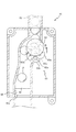
図1は、第1実施例のパチンコ機1の正面図である。パチンコ機1の前面(図1の紙面に対して手前側)には遊技盤2が配設されている。
【0013】
遊技盤2の前面には略円弧状の外レール3が植立され、その外レール3の内側位置には円弧状の内レール4が植立されている。この内レール4および外レール3により囲まれた遊技盤2の前面には、球(打球)Pが打ち込まれる遊技領域5が形成されており、遊技領域5の周囲には、球Pが入賞することにより所定数(例えば、5個)の球Pが賞球として払い出される複数の普通入賞口6が配設されている。この複数の普通入賞口6が配設された遊技領域5の略中央部分には、複数種類の識別情報としての図柄等を表示する液晶ディスプレイ(LCD)7を備えた可変表示装置8が配設されている。なお、液晶ディスプレイ7に代えて、例えば、リール等を用いて可変表示装置を構成するようにしても良い。
【0014】
遊技盤2の右斜め上方向には、パチンコ機1で発生した異常等を遊技者に示唆するためのエラー報知ランプ46が配設されている。このエラー報知ランプ46は、後述する払出カウントスイッチ66のカウント異常(エラー)や、同じく後述する払出用モータ62の駆動異常等が発生した場合に点灯されるランプである。遊技者は、このエラー報知ランプ46が点灯していることを認識することによって、パチンコ機1において何かしらの異常が発生していることを察知させることができる。従って、エラー報知ランプ46が点灯していた場合、遊技者は遊技を停止すると共に遊技場の従業員等に呼び掛け、その異常を解消させ得ることができる。
【0015】
可変表示装置8の下方には、図柄作動ゲート(第1種始動口)9が配設されている。図柄作動ゲート9を球Pが通過することにより、第1種始動口スイッチ39(図2参照)がオンして、上述した可変表示装置8の変動表示が開始されると共に、所定数の球Pが賞球として払い出される。また、図柄作動ゲート9の下方には可変入賞装置10が配設されており、この可変入賞装置10の略中央部分には大入賞口の開口10aが穿設されている。この大入賞口の開口10aは、可変表示装置8の変動後の表示結果が予め定められた図柄の組み合わせ(大当たり表示)の1つと一致する場合に、球Pが入賞し易いように所定時間(例えば、30秒)経過するまで、又は、所定個数(例えば、10個)の球Pが大入賞口の開口10aへ入賞するまで、開放されるものである。この大入賞口の開口10aの開閉動作の行われ得る状態が、いわゆる所定の遊技価値が付与された状態(特別遊技状態、通称、「大当たり」状態)である。
【0016】
可変入賞装置10の下方であって上述した遊技領域5外には前面扉板(腰板)11が配設され、この前面扉板11の前面には、球Pを貯留し、かつ、遊技領域5内に球Pを打ち込む球発射装置(図示せず)へ球Pを供給する上皿12が配設されている。上皿12の下方であって、パチンコ機1の下側部分には上皿12に貯留しきれなかった球Pを貯留するための下皿13が配設されている。上皿12の上方における前面扉板11の上部中央には、後述するカード読取ユニット18により読み取られたカードの残高金額を表示するために、7セグメントLEDにより構成された残高表示器14が配設されている。この残高表示器14の右側には、後述するカード読取ユニット18のカード挿入口19に挿入されたカードを取り出す場合に押下される返却ボタン15が配設される一方、残高表示器14の左側には、貸球の払い出し(貸出)を開始する際に押下される貸出ボタン16が配設されている。また、貸出ボタン16の左側上方には貸出ボタン16が押下可能か否かを報知する貸出ボタンランプ17が配設されており、この貸出ボタンランプ17は、貸出ボタン16が押下可能な状態である場合に点灯される一方、貸出ボタン16が押下不可能な状態である場合に消灯される。よって、遊技者は、この貸出ボタンランプ17を視認することにより、貸出ボタン16が押下可能であるか否かを判断することができる。
【0017】
上記のように構成されたパチンコ機1の左側には、正面視長方形状のカード読取ユニット18が並設されている。カード読取ユニット18はカードに記憶された残高金額のデータを読み取るためのものであり、その上下方向における略中央部分には、金銭と同様の有価価値を有するカードを挿入するためのカード挿入口19が配設されている。このカード挿入口19の上方であって、カード読取ユニット18の上部にはカード利用可能ランプ20が配設されており、このカード利用可能ランプ20は、例えば、カード挿入口19へカードが挿入可能である場合に点灯される一方、カード挿入口19へカードが挿入不可能である場合に消灯される。よって、遊技者は、このカード利用可能ランプ20を視認することにより、カード読取ユニット18が使用可能であるか否かを判断することができる。
【0018】
カード挿入口19とカード利用可能ランプ20との間部分であって、カード読取ユニット18の上側位置には、カードに記録された残高金額のデータに基づいて貸出金額を設定するための金額設定ボタン21が配設されており、この金額設定ボタン21を押下することにより貸出金額を100円、200円、300円又は500円に設定することができる。なお、通常、貸出金額は500円に設定されており、100円分の貸球(例えば、25球)に相当する球Pの払い出しを計5回(例えば、125球)行うものである。
【0019】
金額設定ボタン21の下側には、端数表示ボタン22が配設されている。この端数表示ボタン22は、カードに記憶された残高金額が貸出金額の最低額(例えば、100円)に満たない場合に、その端数を残高表示器14に表示する際に押下されるものである。
【0020】
端数表示ボタン22の下側には、略三角形状に形成された上下一対の連結台方向表示ランプ23が配設されている。この一対の連結台方向表示ランプ23は、カード読取ユニット18が接続されているパチンコ機1の配設(並設)方向を示すためのものであり、その内部にそれぞれ1つずつLEDが内蔵されている。よって、例えば、カード読取ユニット18が左側に並設されるパチンコ機(図示せず)に接続される場合には上側のLEDが点灯されるのである。この連結台方向表示ランプ23の下側には、1つのLEDで構成されたカード挿入中ランプ24が配設されており、このカード挿入中ランプ24は、カードがカード挿入口19に挿入されている場合に消灯される一方、カードがカード挿入口19に挿入されていない場合に消灯される。尚、カード利用可能ランプ20および連結台方向表示ランプ23は、カード読取ユニット18の電源投入とともに点灯される。
【0021】
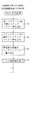
図2は、パチンコ機1の電気的構成を示したブロック図であり、特に、パチンコ機1の遊技内容の制御を行う主制御基板Cと、賞球や貸球の払出制御を行う払出制御基板Hとの電気的構成を示したブロック図である。
【0022】
パチンコ機1の主制御基板Cは、演算装置であるMPU31と、そのMPU31により実行される各種の制御プログラムや固定値データ等を記憶したROM32と、ワークメモリ等として使用されるRAM33とを備えている。図4から図8に示すフローチャートのプログラムは、ROM32内に記憶されている。
【0023】
RAM33には、バックアップエリア33aと、賞球バッファ33bと、賞球ポインタ33cと、残賞球数カウンタ33dと、タンク球無フラグ33eと、下皿満タンフラグ33fとが設けられている。
【0024】
バックアップエリア33aは、停電などの発生により電源が切断された場合、電源の再入時に、パチンコ機1の状態を電源切断前の状態に復帰させるため、電源切断時(停電発生時を含む。以下、同様)のスタックポインタや、各レジスタ、I/O等の値を記憶しておくためのエリアである。このバックアップエリア33aへの書き込みは、NMI割込処理(図4参照)によって電源切断時に実行され、逆にバックアップエリア33aに書き込まれた各値の復帰は、電源入時(停電解消による電源入を含む。以下、同様)の復帰処理(停電処理)において実行される(図6のS15,S16参照)。
【0025】
賞球バッファ33bは、遊技領域5へ打ち込まれた球Pが普通入賞口6等へ入賞した場合に、払い出される賞球数を記憶するバッファである。払い出される賞球数は、入賞した球P毎に賞球バッファ33bへ記憶される。このため、賞球バッファ33bは、複数バイトで構成されている。賞球バッファ33bに記憶された賞球数データは、賞球コマンドとして図7の賞球数データ送信処理によって払出制御基板Hへ送信されると、賞球バッファ33bから消去される。具体的には、0番目の賞球バッファ33bに記憶される賞球数を払出制御基板Hへ送信した後、1番目以降の賞球バッファ33bの値を小さいアドレス側へ順に1バイトずつシフトすることにより、0番目の賞球バッファ33bの値が消去される。
【0026】
ここで、賞球コマンドとは、払い出される賞球数を払出制御基板Hへ指示するためのコマンドであり、2バイトで構成されている。賞球コマンドの1バイト目のデータは、そのコマンドが賞球コマンドであることを示すためのデータ(例えば「A0H」)とされており、また、2バイト目のデータは払い出される賞球数を示すデータとされている。1回の入賞に対する最大の賞球数は15球であるので、その最大賞球数に対応した「01H」〜「0FH」の15種類のデータが賞球コマンドの2バイト目のデータとされている。
【0027】
なお、賞球コマンドを1バイトで構成するようにしても良い。前記した通り、1回の入賞に対する最大の賞球数は15球であるので、賞球コマンドを1バイトで構成する場合には、その最大賞球数に対応した「01H」〜「0FH」の15種類のデータを賞球コマンドとする。即ち、1バイトで構成されるコマンドの上位4ビットが「0」の場合に賞球コマンドとする。
【0028】
賞球ポインタ33cは、賞球数を記憶させる賞球バッファ33bの位置を示すポインタであり、払い出される賞球数は、賞球ポインタ33cの値番目の賞球バッファ33bへ記憶される。この賞球ポインタ33cの値は、賞球バッファ33bへ賞球数を書き込むことにより「1」加算され、0番目の賞球バッファ33bの値が賞球数データ送信処理(S37)によって払出制御基板Hへ送信されることにより「1」減算される。
【0029】
残賞球数カウンタ33dは、未払いの賞球数を記憶するカウンタであり、払出制御基板Hによって払い出される賞球数を主制御基板Cで管理するためのカウンタである。残賞球数カウンタ33dの値は、主制御基板Cが払出制御基板Hへ賞球の払い出しを指示する毎に、その指示した数が加算され、逆に、払出制御基板Hによって賞球の払い出しが行われて、その払い出された賞球を払出カウントスイッチ66が検出する毎に「1」ずつ減算される。
【0030】
タンク球無フラグ33eは、パチンコ機1の裏側に配設される球貯留タンク(図示せず)の球の貯留状態を判断するためのフラグである。このタンク球無フラグ33eは、球貯留タンクに球がなくなった場合、即ち、後述するタンク球無スイッチ42がオンされた場合に、オンされる。逆に、球貯留タンクに球が貯留されている場合はオフされる。このタンク球無フラグ33eがオンされると、払出用モータ駆動停止コマンドが主制御基板Cから払出制御基板Hへ送信され、払出用モータ62の駆動を停止し、球の払い出し動作を停止する。
【0031】
下皿満タンフラグ33fは、下皿13における球の貯留状態を判断するためのフラグである。この下皿満タンフラグ33fは、下皿13に貯留される球が満タン状態、即ち、後述する下皿満タンスイッチ43がオンの状態に、オンされる。逆に、下皿13に貯留される球が満タン状態でない場合にオフされる。この下皿満タンフラグ33fがオンされると、タンク球無フラグ33eと同様に、払出用モータ駆動停止コマンドが主制御基板Cから払出制御基板Hへ送信され、払出用モータ62の駆動を停止し、払い出し動作を停止する。
【0032】
これらROM32及びRAM33を内蔵したMPU31は入出力ポート35と接続されており、入出力ポート35は、複数の信号線37を介して払出制御基板Hと双方向通信可能に接続されるほか、普通入賞口スイッチ38と、第1種始動口スイッチ39と、Vカウントスイッチ40と、10カウントスイッチ41と、タンク球無スイッチ42と、下皿満タンスイッチ43と、払出カウントスイッチ66と、他の入出力装置45とそれぞれ接続されている。
【0033】
普通入賞口スイッチ38は、遊技領域5内の普通入賞口6へ入賞した球Pを検出するためのスイッチであり、普通入賞口6の入口近傍に設けられている。また、第1種始動口スイッチ39は、図柄作動ゲート(第1種始動口)9を通過した球Pを検出するためのスイッチであり、図柄作動ゲート9の近傍に設けられている。普通入賞口スイッチ38或いは第1種始動口スイッチ39により球Pが検出されると、普通入賞口6または図柄作動ゲート(第1種始動口)9への入賞により払い出される賞球数の「5」が、賞球ポインタ33cの値番目の賞球バッファ33bへ書き込まれ、賞球ポインタ33cの値が「1」加算される。
【0034】
Vカウントスイッチ40は、可変入賞装置10により構成される大入賞口へ入賞し、且つ、その大入賞口内のVゾーン(図示せず)を通過した球Pを検出するためのスイッチである。また、10カウントスイッチ41は、可変入賞装置10により構成される大入賞口へ入賞した球Pのうち、Vゾーン以外を通過した球Pを検出するためのスイッチである。Vカウントスイッチ40または10カウントスイッチ41により球Pが検出されると、大入賞口への入賞により払い出される賞球数の「15」が、賞球ポインタ33cの値番目の賞球バッファ33bへ書き込まれ、賞球ポインタ33cの値が「1」加算される。
【0035】
従来のパチンコ機では、払出異常時、即ち、遊技者に正常に球を払い出すことができないとき、払出用モータの駆動を規制して、遊技者に球が払い出されない状況になるように構成されている。しかし、上記のように構成されたパチンコ機では、球噛みによる払出用モータの駆動異常等の些細な払出異常によって遊技が停止してしまうと、遊技場の従業員等によって払出異常を解消してもらわない限り遊技が停止されてしまうので、遊技の進行が遅々として進行せず、遊技者に不利益を被らせ兼ねないといった問題点があった。具体的に説明すると、例えば、大当たり中において払出異常が発生した場合、それ以降遊技者に球が払い出されず、遊技領域へ打ち出す球が球切れとなってしまう。即ち、遊技領域へ打ち出す球が無くなっているので、所定時間経過してしまうことによって大当たりの継続権利を取得できず、大当たりに見合う遊技価値を得ることなくその大当たりが終了してしまうといった問題点があった。
【0036】
また、従来のパチンコ機では、払出異常時、即ち、遊技者に正常に球を払い出すことができないとき、払出用モータの駆動を規制すると共に、簡易なエラー解除動作(リトライ動作)、例えば、払出用モータの正逆回転処理等を繰り返し実行して、その払出異常を解消し得るように構成されている。しかし、例えば、正逆回転処理では解消することができない程度の払出異常が発生してしまった場合、パチンコ機は遊技場の従業員等によって払出異常を解消してもらわない限りエラー解除動作を繰り返し実行してしまい、払出用モータ等の払出装置に負担をかけてしまうといった問題点があった。
【0037】
そこで、第1実施例のパチンコ機1では、払出異常時に上記した各スイッチ38〜41に球が入賞した場合、遊技を再開し得るように構成されている。具体的に説明すると、払出異常の発生による払出用モータ62の駆動規制時において、エラー復帰ボタン44が所定操作されなくても、払出制御基板Hが主制御基板Cから払出指示を受信することによって、払出用モータ62の駆動規制を解除して遊技を再開し得ることができるように構成されている。かかる構成によって、払出用モータ62等の払出装置にかかる負担を軽減することができると共に、些細な払出異常によって球の払い出しが滞ってしまった場合でも、遊技の進行を遅らせることなく払出用モータ62の駆動規制を解除し得ることができるので、遊技者に不利益を被らせずに円滑な遊技を行うことができる。
【0038】
タンク球無スイッチ42は、パチンコ機1の裏側に配設される球貯留タンク(図示せず)に貯留されている球Pの貯留状態を監視するためのスイッチである。このタンク球無スイッチ42は、球Pが球貯留タンクに無くなった場合にオンされ、後述するタンク球無フラグ33eをオンするように構成されている。賞球または貸球の払い出しには、球貯留タンクに貯留されている球Pを使用するため、球貯留タンクに貯留されている球Pが無くなると払い出しが不可能となる。従って、第1実施例のパチンコ機1では、タンク球無スイッチ42により球貯留タンクの球Pの貯留状態を監視し、該スイッチ42によって球貯留タンクに球Pが貯留されていないことが検出された場合は、タンク球無しフラグ33eをオンして、払出用モータ駆動停止コマンドを払出制御基板Hに送信し、払出用モータ62を停止するように構成されている。
【0039】
下皿満タンスイッチ43は、上皿12に貯留しきれなかった球Pを貯留する下皿13が球Pで満タンか否かを監視するためのスイッチである。この下皿満タンスイッチ43は、下皿13が球Pによって満タン状態となった場合にオンされ、後述する下皿満タンフラグ33fをオンするように構成されている。下皿13は、上皿12で球Pを貯留しきれなかった場合に貯留しきれなかった球Pを貯留するために設けられており、下皿13が球Pで満タンになっている場合に賞球または貸球の払い出しを行うと、後述する球払出装置60(図3参照)内で球詰まり等が発生してしまう。従って、第1実施例のパチンコ機1では、下皿満タンスイッチ43により下皿13の球の貯留状態を監視し、該スイッチ43によって下皿13に貯留されている球Pが満タン状態であることが検出された場合は、下皿満タンフラグ33fをオンして、払出用モータ駆動停止コマンドを払出制御基板Hに送信し、払出用モータ62を停止するように構成されている。
【0040】
払出カウントスイッチ66は、払出制御基板Hによって払い出される賞球数をカウントするためのスイッチであり、その出力は主制御基板Cおよび払出制御基板Hへ入力されている。この払出カウントスイッチ66によって、本来の賞球数を越えた賞球の払い出しや本来の賞球数に満たない賞球の払い出しがチェックされる。
【0041】
払出制御基板Hは、賞球や貸球の払出制御を行うものであり、演算装置であるMPU51と、そのMPU51により実行される制御プログラムや固定データ等を記憶したROM52と、ワークメモリ等として使用されるRAM53とを備えている。図4及び図6、並びに、図8から図16に示すフローチャートのプログラムは、ROM52内に記憶されている。また、払出制御基板HのRAM53には、バックアップエリア53aと、受信バッファ53bと、コマンド受信フラグ53cと、総賞球数カウンタ53dと、賞球払出カウンタ53eと、貸球払出カウンタ53fと、貸球払出中フラグ53gと、払出実行フラグ53hと、タイマカウンタ53iと、パルス計数カウンタ53jと、カウントエラーフラグ53kと、モータエラーフラグ53lと、異常回数カウンタ53mと、賞球数データ受信フラグ53nとが設けられている。
【0042】
バックアップエリア53aは、前述した主制御基板Cのバックアップエリア33aと同様に、停電などの発生により電源が切断された場合、電源の再入時に、パチンコ機1の状態を電源切断前の状態に復帰させるため、電源切断時(停電発生時を含む。以下、同様)のスタックポインタや、各レジスタ、I/O等の値を記憶しておくためのエリアである。このバックアップエリア53aへの書き込みは、NMI割込処理(図4参照)によって電源切断時に実行され、逆にバックアップエリア53aに書き込まれた各値の復帰は、電源入時(停電解消による電源入を含む。以下、同様)の復帰処理(停電処理)において実行される(図6、S35〜S37参照)。
【0043】
受信バッファ53bは、主制御基板Cから送信されるデータ(例えば、賞球数データ)を一時的に記憶するバッファである。コマンド受信フラグ53cは、主制御基板Cから払出制御基板Hに制御用コマンドが送信された場合にオンされるフラグである。即ち、主制御基板Cから送信されたデータ(制御用コマンド)が受信バッファ53bに記憶されているとオンされ、そのデータがROM52に記憶されている制御プログラムの各処理により各メモリのいずれかに書き込まれるとオフされるように構成されている。第1実施例のパチンコ機1において、このコマンド受信フラグ53cは、賞球数データが主制御基板Cから送信されたか否かを確認するために、賞球動作処理(S62)において参照される。
【0044】
総賞球数カウンタ53dは、主制御基板Cから指示された賞球の払い出し個数を記憶するためのカウンタである。主制御基板Cから送信された賞球数データからなる賞球コマンドが払出制御基板Hによって受信されると、その賞球コマンドに応じた賞球数データは、一旦、受信バッファ53bに書き込まれ、受信バッファ53bに書き込まれた賞球数データが総賞球数カウンタ53dへ加算されるように構成されている(図10、S73参照)。この総賞球数カウンタ53dに書き込まれた賞球数データは、賞球の払い出し動作が可能であると判断された場合に、後述する賞球払出カウンタ53eに加算される(図10、S78参照)。
【0045】
賞球払出カウンタ53eは、払い出すべき賞球数を記憶するカウンタである。この賞球払出カウンタ53eの値は、賞球の払い出し動作が可能であると判断された場合、即ち、貸球の払い出し動作が実行されていない場合に、前記した総賞球数カウンタ53dの値が加算されるように構成されている(図10、S78参照)。賞球払出カウンタ53eの値が「1」以上である場合には、後述する貸球払出カウンタ53fの値にかかわらず、図12の払出処理(S64)によって賞球の払い出し動作が行われる。即ち、第1実施例のパチンコ機1では、賞球の払い出し動作が貸球の払い出し動作に優先して行われる。また、賞球払出カウンタ53eの値は、図13の払出スイッチ検出処理(S97)において、払出カウントスイッチ66によって払い出された賞球が検出される毎に、「1」ずつ減算される。
【0046】
貸球払出カウンタ53fは、払い出すべき貸球の数を記憶するカウンタである。貸球は貸出金額100円毎に25球ずつ貸し出されるように構成されているので、1の球貸し要求毎に貸球払出カウンタ53fの値に「25」が設定される。貸球払出カウンタ53fの値が「1」以上で且つ賞球払出カウンタ53eの値が「0」である場合には、図12の払出処理(S64)によって貸球の払い出し動作が行われる。貸球払出カウンタ53fの値は、図13の払出スイッチ検出処理(S97)において、払出カウントスイッチ66によって払い出された貸球が検出される毎に「1」ずつ減算される。
【0047】
貸球払出中フラグ53gは、貸球の払い出し動作中(球貸し動作中)であることを示すフラグである。この貸球払出中フラグ53gは、球貸し要求が発生したと共に、賞球払出カウンタ53eの値が「0」である場合、即ち、賞球の払い出し動作が実行されていない場合にオンされ、逆に、球貸し動作が終了した場合、即ち、貸球払出カウンタ53fの値が「0」となった場合にオフされる。この貸球払出中フラグ53gによって、貸球の払い出し動作中の賞球の払い出し、または、賞球の払い出し動作中の貸球の払い出しを制限することができるので、賞球と貸球との払い出し動作を混在させずに、賞球または貸球の払い出し動作を明確に区別することができ、安定した払い出し動作を実行することが可能となる。
【0048】
払出実行フラグ53hは、賞球または貸球の払い出しが開始されたことを示すためのフラグである。この払出実行フラグ53hは、賞球払出カウンタ53e又は貸球払出カウンタ53fの値が「1」以上である場合、即ち、賞球又は貸球が払い出される場合にオンされる(図12参照)。逆に、賞球又は貸球の払い出しが払出カウントスイッチ66によって検出された場合に、賞球払出カウンタ53e及び貸球払出カウンタ53fの値が「0」となったとき、即ち、賞球及び貸球の払い出し動作が終了したときにオフされる(図13参照)。また、払出異常時、即ち、後述するカウントエラーフラグ53k又はモータエラーフラグ53lがオンされている場合に、後述する賞球数データ受信フラグ53nがオンされたとき、言い換えれば、いずれかのスイッチ38〜41に球が入賞して主制御基板Cから賞球数データのコマンドを受信したときに、オフされる(図12、S108参照)。
【0049】
この払出実行フラグ53hがオンされている状態において、後述するタイマカウンタ53i又はパルス計数カウンタ53jの値を判別することによって、払出用モータ62によって払い出された賞球または貸球が正常に払い出されているか否かが判別することができる。
【0050】
タイマカウンタ53iは、賞球又は貸球が払い出されてからの経過時間を計測するためのカウンタである。このタイマカウンタ53iの値は、賞球払出カウンタ53e及び貸球払出カウンタ53fの値が「0」の場合、即ち、賞球又は貸球の払い出しが行われない場合に「0」クリアされる。また、タイマカウンタ53iの値は、賞球又は貸球が所定時間内に検出されない場合のエラー時において「0」クリアされるように構成されている。一方、このタイマカウンタ53iの値は、払出制御基板Hのメイン処理が1回実行される毎に「1」ずつ加算されるように構成されている(図9、S67及びS68参照)。タイマカウンタ53iの値が、払出用モータ62の駆動異常が発生していない状態であると共に、払出実行フラグ53hがオンされたまま、即ち、払出カウントスイッチ66によって賞球または貸球が検出されないまま「1000」となった場合に、払出制御基板Hは、払出カウントスイッチ66が正常に作動していないと判断し、後述するカウントエラーフラグ53kをオンして、以後の払出用モータ62の駆動を規制する。
【0051】
第1実施例のパチンコ機1の払出制御基板Hのメイン処理は、約2ms毎に行われるように構成されている。即ち、払出制御基板Hは、賞球等の払出指示を行ってから、約2秒が経過するまでに払出カウントスイッチ66のいずれかによって球Pが検出されていない場合は、払い出し動作を停止するように構成されている。
【0052】
パルス計数カウンタ53jは、後述する払出用モータ62の駆動指示のパルス数を計数するためのカウンタである。このパルス計数カウンタ53jの値は、賞球払出カウンタ53e及び貸球払出カウンタ53fの値が「0」の場合、即ち、賞球及び貸球の払い出しが行われない場合に「0」クリアされる。また、パルス計数カウンタ53jの値は、後述するスリットセンサ63eによってスリット63dが現出された場合に「0」クリアされるように構成されている。一方、このパルス計数カウンタ53jの値は、ステッピングモータである払出用モータ62を1ステップ駆動するために1パルスの信号を出力する毎に「1」ずつ加算されるように構成されている(図16参照)。
【0053】
第1実施例のパチンコ機1では、払出用モータ62に30パルスの信号を出力することによって1の球を払い出すように構成されている。よって、賞球又は貸球を払い出す場合に、払出用モータ62の駆動を検出していないと共に、パルス計数カウンタ53jの値が「45」以上になったとき、球噛み等によって後述する搬送板63a,63bが正常に駆動していないとみなして、後述するモータエラーフラグ53lをオンするように構成されている。即ち、カウントエラーフラグ53kがオンされていないと共に、払出実行フラグ53hがオンされた状態で、後述するスリットセンサ63eによって後述する搬送板63a,63bに穿設されたスリット63dを検出せずに、パルス計数カウンタ53jの値が「45」以上となった場合に、払出制御基板Hは払出用モータ62が正常に作動していないか、搬送板63a,63bにおいて球噛みが発生していると判断し、後述するモータエラーフラグ53lをオンして、以降の払出用モータ62の駆動を規制する。
【0054】
カウントエラーフラグ53kは、払出用モータ62によって払い出された賞球又は貸球のいずれかが払出カウントスイッチ66によって所定時間内に検出されたか否かを示すためのフラグである。このカウントエラーフラグ53kは、後述するモータエラーフラグ53lがオンしていない場合、即ち、払出用モータ62の駆動異常が発生していない場合に、払出用モータ62に1以上の球の払い出し指示が出力されてから、約2秒経過しても払出カウントスイッチ66によって球Pが検出されない状況を3回繰り返したときにオンされる。逆に、払出カウントスイッチ66によって球が検出された場合にオフされるように構成されている。
【0055】
モータエラーフラグ53lは、払出用モータ62によって駆動される球受け部材63の駆動状況を示すためのフラグである。このモータエラーフラグ53lは、カウントエラーフラグ53kがオンしていない場合、即ち、払出カウントスイッチ66によって球の検出異常が発生していない場合に、払出用モータ62に球1個分の払い出し指示が出力されてから、後述するスリットセンサ63eによって後述する搬送板63a,63bに穿設されたスリット63dを検出せずに、パルス計数カウンタ53jの値が「45」以上となった場合にオンされる。逆に、スリットセンサ63eによってスリット63dが検出された場合にオフされるように構成されている。
【0056】
異常回数カウンタ53mは、払出制御基板Hから払出用モータ62に払出指示を出力してから約2秒が経過したにもかかわらず、払出カウントスイッチ66によって球が検出されなかった回数を計数するためのカウンタである。この異常回数カウンタ53mの値は、払出実行フラグ53hがオンされている状態において、タイマカウンタ53iの値が「1000」となった場合に「1」加算される。逆に、カウントエラーフラグ53kがオンされた場合、即ち、異常回数カウンタ53mの値が「3」となって払出カウントスイッチ66のカウント異常が発生した場合に「0」クリアされるように構成されている。
【0057】
第1実施例では、異常回数カウンタ53mの値が「3」となった場合、即ち、払出実行フラグ53hがオンのままタイマカウンタ53iの値が3回「1000」に到達した場合に、払出カウントスイッチ66のカウント異常と見なして、払出用モータ62の駆動を規制するためにカウントエラーフラグ53kをオンするように構成されている。また、異常回数カウンタ53kの値が「1」加算される毎に払出用モータ62の正逆回転処理を実行して、払出用モータ62の球噛みを解消し得るように構成されている。上記のように構成することによって、遊技の進行を大幅に遅らせることなく、払出用モータ62における軽度な球噛み等の些細な払出異常を解消し得ることができる。
【0058】
賞球数データ受信フラグ53nは、主制御基板Cから賞球数データのコマンドを受信したか否かを確認するためのフラグである。この賞球数データ受信フラグ53nは、主制御基板Cから受信したコマンドが賞球数データのコマンドであった場合、即ち、受信バッファ53bに記憶されているデータが賞球数データのコマンドであった場合にオンされる。逆に、後述する払出処理(図12参照)が実行される毎にオフされる。
【0059】
第1実施例のパチンコ機1では、払出異常が発生している状態において、この賞球数データ受信フラグ53nがオンされることによって、カウントエラーフラグ53k及びモータエラーフラグ53l、並びに、払出実行フラグ53hがオフされるように構成されている。即ち、払出異常時に主制御基板Cから賞球数データのコマンドを受信した場合に、払出用モータ62の駆動規制を行うカウントエラーフラグ53k及びモータエラーフラグ53lをオフすることによって、払出用モータ62の駆動規制を解除して駆動可能な状態にすることができる。また、払出異常時に賞球数データ受信フラグ53nがオンされた場合に、払出実行フラグ53hをオフすることによって、払出制御基板Hは払出用モータ62に再び払出指示を出力することができる。
【0060】
かかるROM52及びRAM53を内蔵したMPU51は入出力ポート55と接続されており、入出力ポート55は、複数の信号線37を介して主制御基板Cと双方向通信可能に接続されるほか、カード操作ユニット14〜17と、カード読取ユニット18と、ドライバ回路57と、払出カウントスイッチ66と、スリットセンサ63eと、エラー復帰ボタン44と、エラー報知ランプ46と、他の入出力装置45と、それぞれ接続されている。
【0061】
ドライバ回路57は、払出用モータ62を駆動し回転させるための回路である。このドライバ回路57により払出用モータ62が回転されると、球受け部材63(図3参照)が回転して賞球又は貸球の払い出しが行われる。
【0062】
払出用モータ62は、後述する球受け部材63を回転駆動するための装置である。第1実施例のパチンコ機1に使用されるモータはステッピングモータであり、払出制御基板HのMPU51から出力される1のパルス信号によって1ステップ(第1実施例では2度)駆動するように構成されている。また、30パルスの信号を払出用モータ62へ出力することによって、1の球が払い出されるように構成されている。
【0063】
スリットセンサ63eは、後述する球払出装置60に配設された球受け部材63の搬送板63a,63bに穿設された複数のスリット63dを検出するためのセンサである。スリットセンサ63eは、球受け部材63の駆動に干渉しない位置に配設されると共に、各スリット63dを検出可能な位置に配設されている。このスリットセンサ63eによって、払出用モータ62によって回転駆動される球受け部材63の駆動量が検出される。従って、賞球又は貸球を払い出す貯めにパルス信号が払出用モータ62へ出力されているにもかかわらず、このスリットセンサ63eによって後述する搬送板63a,63bに穿設されたスリット63dを検出せずに、パルス計数カウンタ53jの値が「45」以上となった場合に、モータエラーフラグ53lをオンして、払出用モータ62の駆動を制限(停止)するように構成されている。
【0064】
エラー復帰ボタン44は、賞球又は貸球の払い出し動作が滞っている場合、即ち、カウントエラーフラグ53k又はモータエラーフラグ53lがオンされている場合に、その払出用モータ62のみの駆動制限を解除させるためのボタンである。第1実施例のパチンコ機1では、このエラー復帰ボタン44が遊技場の従業員によって押下されると、払出用モータ62から2個の球Pが払い出されるように構成されている。その後、払出カウントスイッチ66によって払い出した球が検出されると共に、スリットセンサ63e及び各スリット63dによって球受け部材63の駆動が確認された場合は、払出制御基板Hは球の払出異常が解消して球の払い出しが正常に戻ったことを認識して、払出用モータ62の駆動制限及び遊技停止状態を解除するように構成されている。逆に、払出カウントスイッチ66によって払い出された球が検出されていない場合、又は、スリットセンサ63e及び各スリット63dによって球受け部材63の駆動が確認されずにパルス計数カウンタ53jの値が「45」以上となった場合には、払出制御基板Hは球の払出異常が解消されずに球の払い出しが異常状態のままであることを認識して、再び、払出用モータ62の駆動を規制(停止)するように構成されている。
【0065】
なお、エラー復帰ボタン44は、パチンコ機1の裏側に配設されており(図示せず)、遊技場(ホール)に配設された状態では、鍵等を保持する従業員のみ操作可能な位置に配設されている。よって、球詰まり等によって払出用モータ62の駆動が制限された場合、即ち、払出異常(エラー)が発生した場合には、パチンコ機1の遊技者は、遊技場の従業員を呼び、その従業員によってエラーの原因(例えば、球詰まり等)を解消してもらうと共にエラー復帰ボタン44を押下してもらうことによって、払出用モータ62の駆動制限を解除し得るように構成されている。
【0066】
電源基板70は、パチンコ機1の各部に電力を供給するための電源部70aと、停電監視回路70bと、クリアスイッチ70cとを備えている。停電監視回路70bは、停電等の発生による電源断時に、主制御基板CのMPU31のNMI端子へ停電信号71を出力するための回路である。停電監視回路70bは、電源部70aから出力される最も大きい電圧である直流安定24ボルトの電圧を監視し、この電圧が22ボルト未満になった場合に停電(電源断)の発生と判断して、停電信号71を主制御基板C及び払出制御基板Hへ出力するように構成されている。この停電信号71の出力によって、主制御基板C及び払出制御基板Hは、停電の発生を認識し、停電時処理(図4のNMI割込処理)を実行する。なお、電源部70aは、直流安定24ボルトの電圧が22ボルト未満になった後においても、かかる停電時処理の実行に充分な時間の間、制御系の駆動電圧である5ボルトの出力を正常値に維持するように構成されているので、主制御基板C及び払出制御基板Hは、停電時処理を正常に実行することができるものである。
【0067】
クリアスイッチ70cは、主制御基板CのRAM33及び払出制御基板HのRAM53にバックアップされるデータをクリアするためのスイッチであり、押しボタンタイプのスイッチで構成されている。このクリアスイッチ70cが押下された状態でパチンコ機1の電源が投入されると(停電解消による電源入を含む)、主制御基板C及び払出制御基板Hによって、それぞれのRAM33、RAM53のデータがクリアされる。
【0068】
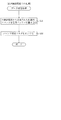
図3は、賞球および貸球の払い出し動作を行う球払出装置60の正面断面図である。球払出装置60は、パチンコ機1の裏面に配設されており(図示せず)、払出制御基板Hにより、賞球払出カウンタ53eまたは貸球払出カウンタ53fの値に応じて、払出用モータ62が制御され、賞球または貸球の払い出し動作を実行するものである。
【0069】
この球払出装置60には、球貯留タンク(図示せず)から供給される球Pを該球払出装置60へ流入させる流入通路61と、その流入した球Pを受け止めて、その下流側へ搬送する球受け部材63とが配設されており、この球受け部材63は、略同一形状に形成された一対の略円形板状の搬送板63a,63bとを備えている。この球受け部材63は、払出用モータ62と連結軸63cを介して連結されており、払出用モータ62の回転に伴って連結軸63cを回転中心として回転されるものである。
【0070】
この球受け部材63の搬送板63a,63bには、それぞれ3つずつ計6個のスリット63dが穿設されている。また、この搬送板63a,63bにはそれぞれ3つずつ計6個の凹部が設けられており、その各凹部に貯留タンク(図示せず)から球Pが落下し、払出用モータ62が回転駆動されることによって凹部に貯留保持された球Pが交互に払い出されるように構成されている。従って、凹部の数と同等のスリット63dを穿設することによって、払い出される球Pの個数分のスリット63dをスリットセンサ63eによって検出可能となる。よって、1の球Pが払い出される場合に、スリットセンサ63eは、必ずいずれか1のスリット63dを検出されるように構成されているので、球受け部材63の駆動を検出することができるのである。
【0071】
また、球受け部材63は、搬送板63a,63bを払出用モータ62によって回転駆動させることにより、搬送板63a,63bから交互に球の払い出し動作が実行されるように構成されている。ここで、払出異常の一つである球噛みが発生した場合は、搬送板63a,63bのいずれかにおいて球噛みが発生している状態である。そこで、第1実施例のパチンコ機1では、駆動異常又は払出異常のエラーが発生した場合に、払出用モータ62を正逆回転駆動させることによって球噛みを解消し得ることができる。また、払出異常中にエラー復帰ボタン44が押下された場合に、払出異常が解消されたか否かを確認するために2の球を払い出すことによって、搬送板63a,63bからそれぞれ1の球が払い出されて、いずれの搬送板63a,63bにおいても球噛みが解消しているか否かを確認することができる。
【0072】
球受け部材63の下流側には、流入通路61と連通する球排出路68が設けられている。この球排出路68の下流部分には該球排出路68を通過する球Pを検出する払出カウントスイッチ66が配設されている。この払出カウントスイッチ66は、球排出路68の一部を構成しており、その略中央部分には球Pが1個ずつ通過可能な円形状の開口である球検出部66aが穿設されている。かかる球検出部66aを球Pが通過することにより、球排出路68を通過した球Pを検出して、払い出された球Pの個数を計数(カウント)することができる。
【0073】
なお、この払出カウントスイッチ66は、磁気センサを備えた近接スイッチで構成されているが、これに代えて、発光ダイオードやフォトトランジスタなどを組み合わせることにより構成される光センサを使用しても良い。
【0074】
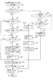
次に、上記のように構成されたパチンコ機1で実行される各処理を、図4から図16の各フローチャートを参照して説明する。図4は、停電の発生等によるパチンコ機1の電源断時に、主制御基板C及び払出制御基板Hで、それぞれ別々に実行されるNMI割込処理のフローチャートである。このNMI割込処理により、停電の発生等による電源断時の主制御基板C及び払出制御基板Hの状態がそれぞれのバックアップエリア33a,53aに記憶される。なお、NMI割込処理は、主制御基板CのROM32と払出制御基板HのROM52とに、それぞれ別々に搭載される処理であるが、フローチャートの表記上、同様に表すことができるので、図4にまとめて図示してある。
【0075】
停電の発生等によりパチンコ機1の電源が断されると、停電監視回路70bから停電信号71が主制御基板C及び払出制御基板HのMPU31,51のNMI(Non Maskable Interrupt)端子へそれぞれ出力される。各MPU31,51は、NMI端子に停電信号71が入力されると、それぞれ実行中の制御を中断して、図4のNMI割込処理を開始する。停電信号71が出力された後所定時間は、主制御基板C及び払出制御基板Hの処理が実行可能なように電源基板70の電源部70aから電力供給がなされており、この所定時間内に、図4のNMI割込処理が実行される。
【0076】
NMI割込処理では、まず、各レジスタおよびI/O等の値をスタックエリアへ書き込み(S1)、次に、スタックポインタの値をバックアップエリア33a,53aへ書き込んで退避する(S2)。更に、停電発生情報をバックアップエリア33a,53aへ書き込んで(S3)、停電の発生等による電源断時の状態を記憶する。その後、主制御基板C及び払出制御基板Hに応じてそれぞれ異なるその他停電処理を実行した後(S4)、電源が完全に断して処理が実行できなくなるまで、処理をループする。
【0077】
次に、図5から図8を参照して、主制御基板Cで行われる各処理について説明する。図5は、所定時間(第1実施例では、2ms)毎に主制御基板Cで実行されるメイン処理のフローチャートである。メイン処理では、まず、RAM33の初期化を含む初期化処理を実行する(S11)。
【0078】
図6は、主制御基板C及び払出制御基板Hで、それぞれ別々に実行される初期化処理(S11、又は、S61)のフローチャートである。なお、初期化処理は、主制御基板CのROM32と払出制御基板HのROM52とに、それぞれ別々に搭載される処理であるが、フローチャートの表記上、同様に表すことができるので、図6にまとめて図示してある。
【0079】
初期化処理では、まず、スタックポインタを設定し(S31)、クリアスイッチ70cがオンされているか否かを確認する(S32)。クリアスイッチ70cがオンされていなければ(S32:No)、バックアップが有効であるか否かを確認する(S33)。この確認は、RAM33,53の所定のエリアに書き込まれたキーワードが正しく記憶されているか否かにより判断する。キーワードが正しくなければバックアップデータは破壊されているので、そのバックアップは有効ではない。
【0080】
バックアップが有効であれば(S33:Yes)、バックアップエリア33a,53aからスタックポインタの値を読み出して、これをスタックポインタへ書き込み、電源断時(停電前)の状態、即ちNMI割込発生前の状態に戻す(S35)。次に、スタックポインタの値を戻した後のスタックエリア、即ちバックアップエリア33a,53aへ退避した各レジスタやI/O等のデータをそのバックアップエリア33a,53aから読み出して、これら各データを元のレジスタやI/O等へ書き込み(S36)、その後、割込の状態を停電発生時に実行される図4の処理で記憶しておいた電源断前(停電前)の状態、即ちNMI割込発生前の状態に戻し(S37)、NMI割込リターンを実行して処理を電源断前に実行していたところへ戻して、制御を電源断前の状態から続行する。
【0081】
一方、クリアスイッチ70cがオンされていたり(S32:Yes)、或いはバックアップが有効でなければ(S33:No)、RAMクリア及び初期化処理を実行して(S34)、RAM33,53及びI/O等の各値を初期化し終了する。初期化処理(S11、又は、S61)の終了後は、図5のメイン処理、又は、図9のメイン処理に戻る。
【0082】
図5に戻って説明すると、初期化処理(S11)の実行後、普通入賞口スイッチ38または第1種始動口スイッチ39により、球Pが検出されたか否かを確認する(S12)。普通入賞口スイッチ38又は第1種始動口スイッチ39により球Pが検出された場合には(S12:Yes)、5個の賞球を払い出すために、賞球ポインタ33cの値番目の賞球バッファ33bへ「5」を書き込み(S13)、賞球ポインタ33cの値を「1」加算して(S14)、処理をS15へ移行する。一方、S12において、普通入賞口スイッチ38又は第1種始動口スイッチ39により球Pが検出されない場合には(S12:No)、S13およびS14の処理をスキップして、S15の処理へ移行する。
【0083】
S15の処理では、Vカウントスイッチ40又は10カウントスイッチ41により球Pが検出されたか否かを確認する(S15)。Vカウントスイッチ40又は10カウントスイッチ41により球Pが検出された場合には(S15:Yes)、15個の賞球を払い出すために、賞球ポインタ33cの値番目の賞球バッファ33bへ「15」を書き込み(S16)、賞球ポインタ33cの値を「1」加算し(S17)、処理をS18へ移行して、賞球バッファ33bに書き込まれた賞球数データを払出制御基板Hへ送信するために、賞球数データ送信処理を実行する(S18)。なお、S15において、Vカウントスイッチ40又は10カウントスイッチ41により球Pが検出されない場合には(S15:No)、S16およびS17の処理をスキップして、S18の賞球数データ送信処理へ移行する。
【0084】
図7は、賞球数データ送信処理(S18)のフローチャートである。賞球数データ送信処理では、まず、賞球ポインタ33cの値が「0」か否かを調べる(S41)。賞球ポインタ33cの値が「0」であれば(S41:Yes)、送信される賞球数データは存在しないので、そのまま、この賞球数データ送信処理を終了する。
【0085】
一方、S41の処理において、賞球ポインタ33cの値が「0」でなければ(S41:No)、0番目の賞球バッファ33bの値を払出制御基板Hへ送信し(S42)、0番目の賞球バッファ33b値を残賞球数カウンタ33dの値へ加算して(S43)、1番目以降の賞球バッファの33bの値を小さいアドレス側へ順に1バイトずつシフトし(S44)、賞球バッファ33bの値を更新するとともに、0番目の賞球バッファ33bの値を消去する。その後、賞球ポインタ33cの値を「1」減算して(S45)、この賞球数データ送信処理を終了する。賞球数データ送信処理(S18)の終了後は、図5のメイン処理に戻って、S19の処理を実行する。
【0086】
S19の処理では、払出カウントスイッチ66がオンされたか否かを判断する(S19)。払出カウントスイッチ66のオンが検出された場合には(S19:Yes)、球が1個払い出されたということなので、その球の払い出しが賞球の払い出し動作であるか否かを確認するために、残賞球数カウンタ33dの値が「0」であるか否かを確認し(S20)、その値が「0」でなければ(S20:No)、払い出された賞球に対応して残賞球数カウンタ33dの値から「1」減算して(S21)、処理をS22へ移行する。
【0087】
なお、S19の処理において、払出カウントスイッチ66のオンが検出されない場合(S19:No)、球が検出されていないので、S20及びS21の処理をスキップして、処理をS22へ移行する。また、払出カウントスイッチ66のオンが検出されても残賞球数カウンタ13dの値が「0」であれば(S19:Yes,S20:Yes)、貸球の払い出し動作等であるので、S21の処理をスキップして、残賞球数カウンタ33dの値を減算せずに、処理をS22へ移行する。
【0088】
S22の処理では、遊技の状態に応じた各処理を実行する(S22)。各処理の実行後は、前回のS12の処理の実行から所定時間(第1実施例では、2ms)経過しているか否かを確認する(S23)。前回のS12の処理の実行から所定時間経過していなければ(S23:No)、所定時間経過するまで待機する一方、前回のS12の処理の実行から所定時間経過していれば(S23:Yes)、処理をS12に移行し、次のメイン処理を開始する。よって、S12からS22までのメイン処理が所定時間の間隔で実行される。
【0089】
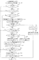
次に、図8から図16を参照して、払出制御基板Hで行われる賞球および貸球の払い出し動作について説明する。図8は、主制御基板Cから送信される制御用コマンドを受信した場合に実行されるデータ受信処理のフローチャートである。
【0090】
データ受信処理では、主制御基板Cから送信された制御用コマンドを受信バッファ53bに書き込み(S51)、コマンド受信フラグ53cをオンする(S52)。賞球数データを指示する賞球コマンドは、このデータ受信処理によって制御用コマンドの一部として受信され、受信バッファ53bへ書き込まれる。
【0091】
図9は、払出制御基板Hにおいて実行されるメイン処理のフローチャートである。この処理では、まず、前述した初期化処理を実行する(S61)。その後、図10に示す賞球動作処理を実行する(S62)。その後、図11に示す球貸し動作処理を実行し(S63)、賞球又は貸球を払い出す払出処理を行って(S64)、その他の各処理を行い(S65)、処理をS66へ移行する。S66の処理では、払出制御基板Hのメイン処理を約2秒間隔で実行するために、前回のS62の処理の実行から所定時間(第1実施例では、約2ms)経過しているか否かを確認し(S66)、前回のS62の処理の実行から所定時間経過していなければ(S66:No)、所定時間経過するまで待機する一方、前回のS62の処理の実行から所定時間経過していれば(S66:Yes)、処理をS67へ移行する。
【0092】
S67の処理では、タイマカウンタ53iの値が「1000」であるか否かを確認する(S67)。タイマカウンタ53iの値が「1000」でなければ(S67:No)、タイマカウンタ53iの値に「1」を加算して(S68)、処理をS62へ移行して、次のメイン処理を開始する一方、タイマカウンタ53iの値が「1000」である場合には(S67:Yes)、S68の処理をスキップして、処理をS62へ移行して、次のメイン処理を開始する。よって、S62からS68までのメイン処理が所定時間の間隔で実行される。
【0093】
図10は、上記した賞球動作処理(S62)のフローチャートである。この賞球動作処理(S62)は、主制御基板Cから受信した賞球数データを、一旦、総賞球数カウンタ53dへ書き込み、賞球の払い出し動作が実行可能な状態であった場合に総賞球数カウンタ53dの値を賞球払出カウンタ53eへ書き込むための処理である。
【0094】
賞球動作処理(S62)では、まず、コマンド受信フラグ53cがオンされているか否かを確認し(S71)、コマンド受信フラグ53cがオンされていれば(S71:Yes)、主制御基板Cから新たな制御用コマンドが払出制御基板Hへ送信されているので、その制御用コマンドが賞球コマンドであるか否かを確認する(S72)。受信バッファ53bに記憶されている制御用コマンドが賞球コマンド、即ち、賞球数データのコマンドであれば(S72:Yes)、その賞球数データを総賞球数カウンタ53dに加算して(S73)、賞球数データ受信フラグ53nをオンし(S74)、コマンド受信フラグ53cをオフして(S75)、処理をS76へ移行する。なお、S71の処理においてコマンド受信フラグ53cがオンされていない場合(S71:No)、又は、S72の処理において受信バッファ53bにあるコマンドは賞球数データのコマンドでない場合には(S72:No)、S73〜S75の処理をスキップして、処理をS76へ移行する。
【0095】
S76の処理では、貸球払出中フラグ53gがオンされているか否かを確認する(S76)。確認の結果、貸球払出中フラグ53gがオンされていなければ(S76:Yes)、貸球の払い出し動作中ではないので、次に、総賞球数カウンタ53dの値が「0」であるか否かを確認する(S77)。総賞球数カウンタ53dの値が「0」でなければ(S77:No)、総賞球数カウンタ53dに賞球数データが記憶されている状態なので、総賞球数カウンタ53dの値を賞球払出カウンタ53eに加算し(S78)、総賞球数カウンタ53dの値を「0」クリアして(S79)、この賞球動作処理(S62)を終了する。なお、S76の処理において、貸球払出中フラグ53gがオンされている場合は(S76:Yes)、貸球の払い出し動作中であるので、その貸球の払い出し動作を優先するためにS77〜S79の処理をスキップして、この賞球動作処理(S62)を終了する。また、S77の処理において、総賞球数カウンタ53dの値が「0」である場合には(S77:Yes)、主制御基板Cから新たな賞球数データを受信していないので、S78及びS79の処理をスキップして、この賞球動作処理(S62)を終了する。なお、賞球動作処理(S62)の終了後は、一旦、図9のメイン処理に戻り、図11に示す球貸し動作処理(S63)を実行する。
【0096】
図11は、上記した球貸し動作処理(S63)のフローチャートである。球貸し動作処理(S63)では、貸出ボタン15が遊技者によって押下されることにより生じる球貸し要求に応じて、貸し出される貸球数を貸球払出カウンタ53fへ設定するための処理である。
【0097】
この球貸し動作処理(S63)では、まず、貸球払出中フラグ53gがオンされているか否かを確認することにより(S81)、球貸し動作中であるか否かを判断する。貸球払出中フラグ53gがオフされていれば(S81:No)、球貸し動作中ではないので、この場合には貸出ボタン15が押下されて球貸し要求があるか否かを確認する(S82)。球貸し要求がなければ(S82:No)、そのまま、この球貸し動作処理を終了する一方、球貸し要求があれば(S82:Yes)、賞球払出カウンタ53eの値が「0」であるか否かを確認する(S83)。賞球払出カウンタ53eの値が「0」でなければ(S83:No)、賞球の払い出し動作中であるので、賞球の払い出し動作を優先するために、この球貸し動作処理(S63)を終了する。
【0098】
球貸し要求があり(S82:Yes)、賞球払出カウンタ53eの値が「0」であれば(S83:Yes)、貸球払出カウンタ53fの値に100円分の貸出金額に相当する貸球の「25」を設定し(S84)、貸球払出中フラグ53gをオンして(S85)、この球貸し動作処理(S63)を終了する。
【0099】
一方、S81の処理において、貸球払出中フラグ53gがオンされていれば(S81:Yes)、球貸し動作中であるので、次に、貸球払出カウンタ53fの値が「0」であるか否かを確認する(S86)。貸球払出カウンタ53fの値が「0」でなければ(S86:No)、未だ前回の球貸し要求分の貸球が払い出されていないので、この球貸し動作処理(S63)を終了する一方、貸球払出カウンタ53fの値が「0」であれば(S86:Yes)、貸球の払い出し動作は終了しているので、貸球払出中フラグ53gをオフして(S87)、この球貸し動作処理(S63)を終了する。球貸し動作処理(S63)の終了後は、一旦、図9のメイン処理に戻り、図10又は図11において設定した賞球払出カウンタ53e又は貸球払出カウンタ53fの値に応じて賞球又は貸球を払い出す払出処理を実行する(S64)。
【0100】
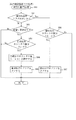
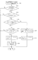
図12は、上記した払出処理(S64)のフローチャートである。この払出処理によって、賞球払出カウンタ53e又は貸球払出カウンタ53fの値に応じて、払出用モータ62が回転駆動され、賞球または貸球の払い出し動作が行われる。
【0101】
この払出処理(S64)では、まず、モータエラーフラグ53l又はカウントエラーフラグ53kがオンされているか否かを確認する(S91)。確認の結果、モータエラーフラグ53l又はカウントエラーフラグ53kがオンされていなければ(S91:No)、払い出し動作が正常に実行可能ということのなので、次に、賞球払出カウンタ53eの値が「0」であるか否かを確認する(S92)。確認の結果、賞球払出カウンタ53eの値が「0」でなければ(S92:No)、払い出すべき賞球数データが記憶されているので、球の払い出し動作を実行するために、処理をS94へ移行する。
【0102】
一方、S92の処理において、賞球払出カウンタ53eの値が「0」である場合には(S92:Yes)、次に、貸球払出カウンタ53fの値が「0」であるか否かを確認する(S93)。確認の結果、貸球払出カウンタ53fの値が「0」でなければ(S93:No)、払い出すべき貸球のデータが記憶されているので、球の払い出し動作を実行するために、処理をS94へ移行する。
【0103】
なお、S92及びS93の処理において、賞球払出カウンタ53e及び貸球払出カウンタ53fの値が共に「0」である場合には(S92:Yes,S93:Yes)、払い出すべき賞球又は貸球のデータは記憶されていないので、かかる場合には払出用モータ62の駆動を停止し(S100)、タイマカウンタ53iの値を「0」クリアすると共に(S101)、パルス計数カウンタ53jの値を「0」クリアして(S102)、賞球数データ受信フラグ53nをオフし(S99)、この払出処理(S64)を終了する。従って、払出指示がない場合には、上記したS100〜S102が実行されるように構成されている。
【0104】
S94の処理では、払出実行フラグ53hがオンされているか否かを確認する(S94)。払出実行フラグ53hがオフされていれば(S94:No)、賞球払出カウンタ53e又は貸球払出カウンタ53fに記憶されている値分の球を払い出すために払出用モータ62を駆動させる(S95)。従って、払出用モータ62の駆動量は、賞球払出カウンタ53e又は貸球払出カウンタ53fに記憶される値に応じて変化するように構成されている。例えば、賞球払出カウンタ53eに記憶される値が「1」であった場合には、30パルスの信号が払出用モータ62に出力されて1球の賞球が払い出されるように構成されている。また、賞球払出カウンタ53eに記憶される値が「15」であった場合には、30パルスに15を乗じた値である450パルスの信号が払出用モータ62に出力されて15球の賞球が払い出されるように構成されている。
【0105】
S95の処理の後は、払出実行フラグ53hをオンして(S96)、賞球払出カウンタ53e又は貸球払出カウンタ53fに記憶された値分の球が払い出されるまでS95の処理を通過しないようにして、処理をS97の払出スイッチ検出処理へ移行する。
【0106】
図13は、払出スイッチ検出処理(S97)のフローチャートである。この払出スイッチ検出処理は、払出用モータ62によって払い出された賞球又は貸球が払出カウントスイッチ66によって検出されている場合には賞球払出カウンタ53e又は貸球払出カウンタ53fの値から「1」を減算する一方、払出用モータ62から払い出された球が約2秒を経過しても払出カウントスイッチ66によって検出されない状況を3回繰り返した場合に、払出異常とみなして、カウントエラーフラグ53kをオンして、以後の払い出し動作を制限(停止)するための処理である。
【0107】
払出スイッチ検出処理(S97)では、まず、払出実行フラグ53hがオンされているか否かを確認する(S111)。払出実行フラグ53hがオンされていなければ(S111:No)、賞球または貸球は払い出しされていないので、この払出スイッチ検出処理(S97)を終了する。一方、払出実行フラグ53hがオンされていれば(S111:Yes)、次に、駆動異常が発生しているか否かを確認するためにモータエラーフラグ53lがオンされているか否かを確認し(S112)、モータエラーフラグ53lがオンされている場合には(S112:Yes)、払出用モータ62の駆動異常が発生しているので、まず、駆動異常を解消するためにこの払出スイッチ検出処理(S97)を終了する。
【0108】
一方、S112の処理で、モータエラーフラグ53lがオンしていなければ(S112:No)、次に、タイマカウンタ53iの値が「1000」であるか否かを確認する(S113)。タイマカウンタ53iの値が「1000」である場合には(S113:Yes)、賞球または貸球が払い出されてから払出カウントスイッチ66で検出されずに約2秒が経過しているので、異常回数カウンタ53mの値に「1」を加算して(S114)、球噛み等を解消するためにモータ正逆回転処理を行い(S115)、次に、異常回数カウンタ53mの値が「3」であるか否かを確認する(S116)。確認の結果、異常回数カウンタ53mの値が「3」でない場合には(S116:No)、払い出しが滞ってから6秒が経過していないので、処理をS117へ移行する。異常回数カウンタ53mの値が「3」である場合には(S116:Yes)、払い出しが滞ってから約6秒経過しているので、カウントエラーフラグ53kをオンして(S126)、異常回数カウンタ53mの値を「0」クリアし(S127)、この払出スイッチ検出処理(S97)を終了する。なお、S113の処理において、タイマカウンタ53iの値が「1000」でなければ(S113:No)、S114〜S116の処理をスキップして、処理をS117へ移行する。
【0109】
S117の処理では、払出カウントスイッチ66が球を検出したか否かを確認する(S117)。確認の結果、払出カウントスイッチ66が球を検出していなければ(S117:No)、この払出スイッチ検出処理(S97)を終了する一方、払出カウントスイッチ66が球を検出していれば(S117:Yes)、その検出された球が賞球であるか貸球であるかを確認するために、賞球払出カウンタ53eの値が「1」以上であるかを確認する(S118)。賞球払出カウンタ53eの値が「1」以上であれば(S118:Yes)、検出された球は賞球として払い出された球であるので、賞球払出カウンタ53eの値から「1」減算し(S119)、処理をS121へ移行する。一方、賞球払出カウンタ53eの値が「1」以上でない場合には(S118:Yes)、検出された球は貸球として払い出された球であるので、貸球カウントスイッチ53fの値から「1」を減算して(S120)、処理をS121へ移行する。
【0110】
S121の処理では、払出カウントスイッチ66が正常に球を検出したので、タイマカウンタ53iの値を「0」クリアして(S121)、カウントエラーフラグ53kをオフし(S122)、次に、賞球払出カウンタ53e及び貸球払出カウンタ53fの値が「0」か否かを確認する(S123)。賞球払出カウンタ53e又は貸球払出カウンタ53fの値が「0」でなければ(S123:No)、払い出すべき賞球又は貸球が残っているので、払出実行フラグ53hをオフすることなくこの払出スイッチ検出処理を終了する。一方、賞球払出カウンタ53e又は貸球払出カウンタ53fの値が「0」であれば(S123:Yes)、払い出すべき賞球又は貸球の払出動作は正常に終了したということなので、払出実行フラグ53hをオフし(S124)、エラー報知ランプ46を消灯して(S125)、この払出スイッチ検出処理(S97)を終了する。従って、第1実施例のパチンコ機1では、払出異常が発生した場合に、払出カウントスイッチ66によって球が検出されるまで、エラー報知ランプ46は点灯した状態を保つように構成されている。よって、一旦、払出異常が発生して遊技が停止した場合に、遊技者に球が正常に払い出されるまでエラー報知ランプ46を点灯し続けることができるので、払出異常が発生していることを遊技者のみにかかわらず、遊技場の従業員等にも認識させ易くすることができる。なお、払出スイッチ検出処理の終了後は、一旦、図12に戻り、次に、図14に示すスリット検出処理を実行する(S98)。
【0111】
図14は、スリット検出処理(S98)のフローチャートである。スリット検出処理は、払出用モータ62によって球受け部材63が正常に作動しているか否かを確認するための処理である。このスリット検出処理と前述した払出スイッチ検出処理とによって、球噛みの発生による払出異常か、払出カウントスイッチ66の検出異常による払出異常かを認識することができる。
【0112】
スリット検出処理(S98)では、まず、払出実行フラグ53hがオンされているか否かを確認する(S131)。確認の結果、払出実行フラグ53hがオンされていなければ(S131:No)、賞球又は貸球の払い出し動作は実行されていないので、このスリット検出処理を終了する。一方、払出実行フラグ53hがオンされている場合は(S131:Yes)、賞球又は貸球の払い出し動作が実行されている状態なので、次に、カウントエラーフラグ53kがオンされているか否かを確認する(S132)。カウントエラーフラグ53kがオンされていれば(S132:Yes)、払出異常が発生している状態なので、まず、その払出異常を解消するべくこのスリット検出処理を終了する。
【0113】
一方、カウントエラーフラグ53kがオンされていなければ(S132:No)、次に、スリットセンサ63eは1のスリット63dを検出したか否かを確認する(S133)。確認の結果、スリットセンサ63eによって1のスリット63dを検出していなければ(S133:No)、次に、パルス計数カウンタ53jの値が「45」以上であるか否かを確認し(S134)、払出用モータ62の駆動指示が発生してから払出用モータ62に45パルスの信号が出力されているか否かを確認する。払出異常カウンタ53jの値が「45」以上である場合には(S134:Yes)、本来、30パルスの信号で1の球が払い出されるにもかかわらず、45パルスの信号でも1の球が払い出されていないということなので、球噛み等の発生によって球受け部材63が正常に駆動していないことを示すために、モータエラーフラグ53lをオンして(S135)、球噛み等を解消するためにモータ正逆回転処理を実行し(S136)、このスリット検出処理(S98)を終了する。
【0114】
なお、S133の処理において、スリットセンサ63eが1のスリット63dを検出している場合は(S133:Yes)、球受け部材63は正常に駆動しているということなので、パルス計数カウンタ53jの値を「0」クリアして(S137)、モータエラーフラグ53lをオフし(S138)、このスリット検出処理を終了する。また、S134の処理において、パルス計数カウンタ53jの値が「45」以上でない場合は(S134:No)、払出用モータ62の駆動指示が発生してから未だ45パルスの信号が出力されていない状態なので、S135及びS136の処理をスキップして、このスリット検出処理を終了する。このスリット検出処理の終了後は、図12に戻って、賞球数データ受信フラグ53nをオフして(S99)、払出処理(S64)を終了する。
【0115】
ここで、図12の払出処理のS91において、モータエラーフラグ53l又はカウントエラーフラグ53kがオンされている場合(S91:Yes)、即ち、払出スイッチ検出処理(S97)において、払出指示が発生してから払出カウントスイッチによって約6秒以内に球が検出されていない払出異常が発生している場合、又は、スリット検出処理(S98)において、払出指示が発生してからスリットセンサ63eが1のスリット63dを検出する前にパルス計数カウンタ53jの値が「45」以上となって払出用モータ62の駆動異常が発生している場合には、払出用モータ62の駆動を規制(停止)するために、処理をS103へ移行する。
【0116】
S103の処理では、賞球数データ受信フラグ53nがオンされているか否かを確認する(S103)。確認の結果、賞球数データ受信フラグ53nがオンされていなければ(S103:No)、主制御基板Cから賞球数データのコマンドは出力されていないので、次に、遊技場の従業員によってエラー復帰ボタン44が押下されたか否かを確認し(S104)、遊技場の従業員によってエラー復帰ボタン44が押下されていない場合には(S104:No)、払出用モータ62の駆動を制限(停止)した状態を保たせるために、エラー報知ランプ46を点灯させ(S105)、処理をS100へ移行する。一方、遊技場の従業員によりエラー復帰ボタン44が押下された場合は(S104:Yes)、払出異常が解消しているか否かを確認するために、球を払い出す復帰時払出処理を実行する(S106)。
【0117】
一方、賞球数データ受信フラグ53nがオンされていれば(S103:Yes)、主制御基板Cから賞球数データのコマンドを受信したということなので、球の入賞に基づいてエラーの復帰処理を実行するために、処理をS106の復帰時払出処理へ移行する。即ち、払出異常の発生による払出用モータ62の駆動規制時において、エラー復帰ボタン44が所定操作されなくても、払出制御基板Hが主制御基板Cから払出指示を受信することによって、復帰時払出処理を実行することで、遊技を再開し得ることができるように構成されている。かかる構成によって、些細な払出異常によって遊技が停止した場合でも、遊技の進行を遅らせることなく再開し得ることができるので、遊技者に不利益を被らせずに円滑な遊技を行うことができる。
【0118】
図15は、復帰時払出処理(S106)のフローチャートである。この復帰時払出処理は、賞球払出カウンタ53e又は貸球払出カウンタ53fに記憶されている値分の球を払い出すために払出用モータ62を駆動させて、払出異常が解消されているか否かを確認するための処理である。
【0119】
復帰時払出処理(S106)では、賞球払出カウンタ53e又は貸球払出カウンタ53fに記憶されている値分の球を払い出すために払出用モータ62を駆動させ(S141)、払い出される球の払い出し動作が正常に行われるか否かを確認するために、その球の払い出し動作が実行される所定時間の間分、ウェイト処理を行い(S142)、この復帰時払出処理(S106)を終了する。この復帰時払出処理の終了後は、図12の払出処理の払出スイッチ検出処理(S97)へ移行する。
【0120】
図16は、払出制御基板Hのメイン処理の中の各処理(S65)の中で実行されるパルスカウント処理のフローチャートである。このパルスカウント処理のよって、払出用モータ62を駆動させる1のパルス信号が出力される毎に、払出用モータ62の駆動異常を監視するパルス計数カウンタ53jの値が「1」ずつ加算される。
【0121】
このパルスカウント処理では、まず、払出用モータ62を1ステップ駆動するために1パルスの信号を払出用モータ62へ出力したか否かを確認する(S151)。確認の結果、払出用モータ62を駆動させるために1パルスの信号が払出用モータ62へ出力されていれば(S151:Yes)、パルス計数カウンタ53jの値を「1」加算して(S152)、このパルスカウント処理を終了する。一方、払出用モータ62を駆動させるために1パルスの信号が払出用モータ62へ出力されていない場合は(S151:No)、S152の処理をスキップして、このパルスカウント処理を終了する。
【0122】
以上説明したように、第1実施例のパチンコ機1では、払出異常の発生による払出用モータ62の駆動規制時において、エラー復帰ボタン44が所定操作されなくても、払出制御基板Hが主制御基板Cから払出指示を受信することによって、遊技を再開し得ることができるように構成されている。かかる構成によって、払出用モータ62等の払出装置にかかる負担を軽減することができると共に、些細な払出異常によって遊技が停止した場合でも、遊技の進行を遅らせることなく進行し得ることができるので、遊技者に不利益を被らせずに円滑な遊技を行うことができる。
【0123】
次に、図17を参照して、第2実施例について説明する。第1実施例のパチンコ機1では、払出異常時における球の入賞に基づいて、払出異常を保った状態で払出用モータ62を再駆動させる復帰処理を実行していた。これに代えて、第2実施例のパチンコ機1では、払出異常時における球の入賞に基づいて、払出異常発生による払出用モータ62の駆動規制を解除して、払出用モータ62を駆動可能な状態にするように構成する。以下、第1実施例と同一の部分には同一の符号を付してその説明を省略し、異なる部分について説明する。
【0124】
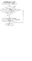
図17は、第2実施例の払出制御基板Hのメイン処理の中で実行される払出処理(S64)のフローチャートである。第2実施例の払出処理において、モータエラーフラグ53l又はカウントエラーフラグ53kがオンされている場合(S91:Yes)、即ち、何らかの払出異常が発生している場合には、払出用モータ62の駆動を規制(停止)するために、処理をS103へ移行する。
【0125】
S103の処理では、賞球数データ受信フラグ53nがオンされているか否かを確認する(S103)。確認の結果、賞球数データ受信フラグ53nがオンされていれば(S103:Yes)、主制御基板Cから賞球数データのコマンドを受信したということなので、モータエラーフラグ53l及びカウントエラーフラグ53kをオフして(S161)、払出用モータ62の駆動規制を解除して球の払い出しが可能な状態にすると共に、払出実行フラグ53hをオフして(S162)、再び払出用モータ62に払出信号を出力可能な状態にし、処理をS99へ移行する。
【0126】
上記のように構成することによって、第2実施例のパチンコ機1では、払出異常の発生による払出用モータ62の駆動規制時において、エラー復帰ボタン44が所定操作されなくても、払出制御基板Hが主制御基板Cから払出指示を受信することによって、遊技を再開し得ることができるように構成されている。かかる構成によって、払出用モータ62等の払出装置にかかる負担を軽減することができると共に、些細な払出異常によって遊技が停止した場合でも、遊技の進行を遅らせることなく進行し得ることができるので、遊技者に不利益を被らせずに円滑な遊技を行うことができる。
【0127】
以上、各実施例に基づき本発明を説明したが、本発明は上記実施例に何ら限定されるものではなく、本発明の趣旨を逸脱しない範囲内で種々の変形改良が可能であることは容易に推察できるものである。
【0128】
例えば、払出異常が発生して遊技の進行が規制された場合に、遊技の進行が規制されたことを示す規制発生情報を遊技場の管理コンピュータ等に出力するように構成しても良い。上記のように構成することによって、遊技場の管理コンピュータにおいてパチンコ機1の状態を正確に把握することができると共に、遊技規制が発生した場合に速やかに従業員等を派遣することができる。
【0129】
本発明を上記実施例とは異なるタイプのパチンコ機等に実施しても良い。例えば、一度大当たりすると、それを含めて複数回(例えば2回、3回)大当たり状態が発生するまで、大当たり期待値が高められるようなパチンコ機(通称、2回権利物、3回権利物と称される)として実施しても良い。また、大当たり図柄が表示された後に、所定の領域に球を入賞させることを必要条件として特別遊技状態となるパチンコ機として実施しても良い。更に、パチンコ機以外にも、アレパチ、雀球、スロットマシン、いわゆるパチンコ機とスロットマシンとが融合した遊技機などの各種遊技機として実施するようにしても良い。
【0130】
なお、スロットマシンは、例えばコインを投入して図柄有効ラインを決定させた状態で操作レバーを操作することにより図柄が変動され、ストップボタンを操作することにより図柄が停止されて確定される周知のものである。従って、スロットマシンの基本概念としては、「複数の図柄からなる図柄列を変動表示した後に図柄を確定表示する可変表示手段を備え、始動用操作手段(例えば操作レバー)の操作に起因して図柄の変動が開始され、停止用操作手段(例えばストップボタン)の操作に起因して、或いは、所定時間経過することにより、図柄の変動が停止され、その停止時の確定図柄が特定図柄であることを必要条件として、遊技者に有利な特別遊技状態を発生させる特別遊技状態発生手段とを備えたスロットマシン」となり、この場合、遊技媒体はコイン、メダル等が代表例として挙げられる。
【0131】
以下に本発明の遊技機及び変形例を示す。遊技の制御を行う主制御手段と、その主制御手段から出力される払出指示に基づいて所定の有価価値を有する有価物体の払出制御を行う払出制御手段と、その払出制御手段によって駆動されて前記有価物体を払い出す払出手段と、その払出手段による払い出し状態を監視する払出監視手段と、その払出監視手段によって前記有価物体の払い出しが異常と判断された場合に遊技の進行を規制する遊技規制手段と、その遊技規制手段によって遊技規制時に所定操作されることで遊技規制を解除する規制解除手段とを備えた遊技機において、前記払出制御手段は、前記遊技規制手段によって遊技規制された場合において、前記主制御手段から前記払出指示を受信した際に前記遊技規制を解除し得る受信時規制解除手段を備えていることを特徴とする遊技機1。払出制御手段は、遊技規制手段によって遊技の進行が規制された場合、即ち、払出異常によって遊技が規制された場合において、受信時規制解除手段によって、主制御手段から払出指示を受信した際に遊技規制を解除し得るように構成されている。言い換えれば、払出異常の発生による遊技規制時において、主制御手段からの払出指示を受信することによって、規制解除手段を介さずに遊技規制を解除し得ることができるように構成されている。よって、些細な払出異常によって遊技の進行が規制された場合でも、遊技の進行を遅らせることなくその規制を解除し得ることができるので、遊技者に不利益を被らせずに円滑な遊技を行うことができる。
【0132】
なお、遊技規制時とは、例えば、遊技機全般の制御が停止した状態や、払い出し動作に関する装置及び制御のみが規制されて表示装置等に関する装置及び制御が正常に実行されている状態等が例示される。
【0133】
遊技機1において、前記遊技規制手段は、遊技の進行が規制された場合に前記払出手段の駆動を規制する駆動規制手段を備え、前記払出制御手段は、前記主制御手段から前記払出指示を受信した場合に、前記駆動規制手段による前記払出手段の駆動規制を解除するものであることを特徴とする遊技機2。駆動規制手段は、遊技規制手段による遊技規制時に払出手段の駆動を規制し、払出制御手段は、遊技規制時に主制御手段から払出指示を受信した場合、払出手段の駆動規制を解除するように構成されている。よって、払出異常の発生による遊技規制時において、主制御手段からの払出指示を受信することによって遊技を再開し得ることができるので、些細な払出異常によって遊技が停止した場合でも、遊技の進行を遅らせることなくその規制を解除し得ることができ、遊技者に不利益を被らせずに円滑な遊技を行うことができる。
【0134】
遊技機1において、前記遊技規制手段は、遊技の進行が規制された場合に前記払出手段の駆動を規制する駆動規制手段を備え、前記払出制御手段は、前記主制御手段から前記払出指示を受信した場合に、前記駆動規制手段による前記払出手段の駆動規制を保ったまま、前記払出手段を駆動させるものであることを特徴とする遊技機3。駆動規制手段は、遊技規制手段による遊技規制時に払出手段の駆動を規制し、払出制御手段は、遊技規制時に主制御手段から払出指示を受信した場合に、払出手段の駆動規制を保ったまま払出手段を駆動させるように構成されている。即ち、払出制御手段は、主制御手段から払出指示を受信した場合に、払出手段の駆動規制が実行されている状態で、1回のみ払出手段を駆動させて有価物体を払い出し得ることができるように構成されている。よって、払出異常の発生による遊技規制時において、主制御手段からの払出指示を受信することによって遊技を再開し得ることができるので、些細な払出異常によって遊技が停止した場合でも、遊技の進行を遅らせることなくその規制を解除し得ることができ、遊技者に不利益を被らせずに円滑な遊技を行うことができる。
【0135】
遊技機1から3のいずれかにおいて、前記主制御手段又は払出制御手段は、前記遊技規制手段による遊技規制時において、遊技の進行が規制されたことを示唆する規制時示唆手段を備え、前記主制御手段又は払出制御手段は、前記払出監視手段によって前記有価物体の払い出しが正常と判断されるまで、前記規制時示唆手段によって遊技の進行が規制されたことを示唆し続けるものであることを特徴とする遊技機4。払出監視手段によって有価物体の払い出しが正常と判断されるまで、規制時示唆手段によって遊技の進行が規制されたことを示唆し続けるように構成されている。よって、一旦、払出異常が発生して遊技が規制された場合に、遊技者に有価物体が正常に払い出されるまで規制時示唆手段によって遊技の進行が規制されていることを示唆し続けることができるので、払出異常が発生していることを遊技者のみにかかわらず、遊技場の従業員等にも認識させ易くすることができる。
【0136】
遊技機1から4のいずれかにおいて、前記主制御手段又は払出制御手段は、前記遊技規制手段によって遊技の進行が規制された場合に、遊技の進行が規制されたことを示す規制発生情報を外部へ出力するものであることを特徴とする遊技機5。遊技の進行が規制された場合に、外部(例えば、遊技場管理装置)に遊技の進行が規制されたことを示す規制発生情報を出力することによって、遊技場管理装置等の外部装置において遊技機の状態を正確に把握することができると共に、遊技規制が発生した場合に速やかに従業員等を派遣することができる。なお、外部とは、遊技場に配備されている各遊技機を管理する遊技場管理装置等が例示される。
【0137】
遊技機1から5のいずれかにおいて、前記遊技機はパチンコ遊技機であることを特徴とする遊技機6。中でも、パチンコ遊技機の基本構成としては操作ハンドルを備え、その操作ハンドルの操作に応じて球を所定の遊技領域へ発射し、球が遊技領域内の所定の位置に配設された作動口に入賞(又は作動口を通過)することを必要条件として、表示装置において動的表示されている識別情報が所定時間後に確定停止されるものが挙げられる。また、特別遊技状態の発生時には、遊技領域内の所定の位置に配設された可変入賞装置(特定入賞口)が所定の態様で開放されて球を入賞可能とし、その入賞個数に応じた有価価値(景品球のみならず、磁気カードへ書き込まれるデータ等も含む)が付与されるものが挙げられる。
【0138】
パチンコ遊技機は、スロットマシン等の遊技機とは異なり、特別遊技状態における遊技に時間制約が設けられている。従って、パチンコ遊技機における特別遊技状態中においては、遊技者は常に遊技に参加している必要があり、例えば、席を立って遊技を中段することや、球切れとなって遊技に参加不能になってしまうと、特別遊技状態に見合った遊技価値を得ることができないように構成されている。このようなパチンコ遊技機において、例えば、特別遊技状態中に払出異常が発生してしまうと、入賞口に球が入賞しても賞球が払い出されず、更には球切れとなってしまい、遊技に参加することができなくなってしまう場合がある。かかる場合には、従業員を呼び、払出異常を解消して貰って再び遊技に参加するわけであるが、特別遊技状態は従業員が払出異常を解消している間も進行しているので、払出異常が解消した後で遊技に参加しても、特別遊技状態に見合った遊技価値を得ることができないといった問題点があった。そこで、払出異常発生時において、入賞口に球が入賞する際に払出異常を解消して再び球を払い出し得るように構成することによって、特別遊技状態中において些細な払出異常によって遊技が停止した場合でも、遊技の進行を遅らせることなく遊技を進行(払い出し動作を実行)し得ることができるので、遊技者に不利益を被らせずに円滑な遊技を行うことができる。
【0139】
遊技機1から5のいずれかにおいて、前記遊技機はスロットマシンであることを特徴とする遊技機7。中でも、スロットマシンの基本構成としては、「複数の識別情報からなる識別情報列を動的表示した後に識別情報を確定表示する可変表示手段を備え、始動用操作手段(例えば操作レバー)の操作に起因して識別情報の動的表示が開始され、停止用操作手段(ストップボタン)の操作に起因して、或いは、所定時間経過することにより、識別情報の動的表示が停止され、その停止時の確定識別情報が特定識別情報であることを必要条件として、遊技者に有利な特別遊技状態を発生させる特別遊技状態発生手段とを備えた遊技機」となる。この場合、遊技媒体はコイン、メダル等が代表例として挙げられる。
【0140】
遊技機1から5のいずれかにおいて、前記遊技機はパチンコ遊技機とスロットマシンとを融合させたものであることを特徴とする遊技機8。中でも、融合させた遊技機の基本構成としては、「複数の識別情報からなる識別情報列を動的表示した後に識別情報を確定表示する可変表示手段を備え、始動用操作手段(例えば操作レバー)の操作に起因して識別情報の変動が開始され、停止用操作手段(例えばストップボタン)の操作に起因して、或いは、所定時間経過することにより、識別情報の動的表示が停止され、その停止時の確定識別情報が特定識別情報であることを必要条件として、遊技者に有利な特別遊技状態を発生させる特別遊技状態発生手段とを備え、遊技媒体として球を使用すると共に、前記識別情報の動的表示の開始に際しては所定数の球を必要とし、特別遊技状態の発生に際しては多くの球が払い出されるように構成されている遊技機」となる。
【図面の簡単な説明】
【図1】 本発明の第1実施例であるパチンコ機の正面図である。
【図2】 パチンコ機の電気的構成を示したブロック図である。
【図3】 球払出装置の断面図である。
【図4】 主制御基板及び払出制御基板で実行されるNMI割込処理のフローチャートである。
【図5】 主制御基板で実行されるメイン処理のフローチャートである。
【図6】 主制御基板及び払出制御基板で実行される初期化処理のフローチャートである。
【図7】 主制御基板で実行される賞球数データ送信処理のフローチャートである。
【図8】 払出制御基板で実行されるデータ受信処理のフローチャートである。
【図9】 払出制御基板で実行されるメイン処理のフローチャートである。
【図10】 払出制御基板のメイン処理の中で実行される賞球動作処理のフローチャートである。
【図11】 払出制御基板のメイン処理の中で実行される球貸し動作処理のフローチャートである。
【図12】 払出制御基板のメイン処理の中で実行される払出処理のフローチャートである。
【図13】 払出処理の中で実行される払出スイッチ検出処理のフローチャートである。
【図14】 払出処理の中で実行されるスリット検出処理のフローチャートである。
【図15】 払出処理の中で実行される復帰時払出処理のフローチャートである。
【図16】 払出制御基板のメイン処理の中の各処理の中で実行されるパルスカウント処理のフローチャートである。
【図17】 第2実施例の払出制御基板のメイン処理の中で実行される払出処理のフローチャートである。
【符号の説明】
1 パチンコ機(遊技機)
44 エラー復帰ボタン(規制解除手段の一部)
53h 払出実行フラグ(払出監視手段の一部)
53i タイマカウンタ(払出監視手段の一部)
53j パルス計数カウンタ(払出監視手段の一部)
53k カウントエラーフラグ(払出規制手段の一部)
53l モータエラーフラグ(払出規制手段の一部)
53m 異常回数カウンタ(払出監視手段の一部)
53n 賞球数データ受信フラグ(受信時停止解除手段の一部)
60 球払出装置(払出手段の一部)
62 払出用モータ(払出手段の一部)
66 払出カウントスイッチ(払出監視手段の一部)
C 主制御基板(主制御手段)
H 払出制御基板(払出制御手段)
P 球(有価物体)[0001]
BACKGROUND OF THE INVENTION
The present invention relates to gaming machines represented by pachinko machines and slot machines.
[0002]
[Prior art]
Conventionally, game control of a gaming machine such as a pachinko machine is mainly performed by a main control board. The main control board drives a payout motor disposed in the ball payout device to win a prize ball Such as Payout control board for payout control Na Is connected. Withdrawal Control board is controlled from main control board Sending This is done based on the command received.
[0003]
The balls to be paid out by the payout control board are provided in the ball payout device. Detection means And the detection signal is output to the main control board or the payout control board, so that it is possible to confirm whether or not the balls are paid out reliably. Here, detect the payout of the ball Detection means If a ball payout abnormality is confirmed due to a failure of the ball or the ball of the payout motor, etc., the drive motor of the payout motor is regulated so that the game is not stopped and the illegal ball is not paid out. It is configured as follows.
[0004]
Also , If a ball withdrawal abnormality occurs, Predetermined When the switch is operated for a predetermined time, the payout abnormality is canceled and the stopped game can be resumed (for example, Patent Document 1).
[0005]
[Patent Document 1]
JP-A-8-224344
[0006]
[Problems to be solved by the invention]
However, if a withdrawal abnormality occurs, If control such as notification of abnormality or monitoring or return of abnormal situation is performed, the control of the game is loaded, and if the game progress control is abnormal, There was a problem that players could suffer disadvantages.
[0008]
The present invention has been made to solve the above-described problems, Proper control of game progress The purpose is to provide a gaming machine.
[0009]
[Means for Solving the Problems]
In order to achieve this object, the gaming machine according to claim 1 is characterized in that a main control means for controlling a game related to a prize for giving a player at least a predetermined game value, and the main control when the prize is generated. A payout control means for performing payout control of a valuable object having a predetermined valuable value based on a payout instruction output from the means, a payout means driven by the payout control means for paying out the valuable object, and the payout means A payout monitoring means for monitoring the payout state, a payout restricting means for restricting the drive of the payout means when the payout monitoring means determines that the payout of the valuable object is abnormal, and the payout restricting means A restriction release means for releasing the drive restriction of the payout means when a predetermined operation is performed when the drive is restricted, and the main control means includes the payout means. Drive of the dispensing means is regulated by the regulating means Without performing control related to the abnormality under circumstances The game control is continued and the payout instruction is output when the winning occurs.
The gaming machine according to claim 2 is the gaming machine according to claim 1, wherein when the driving of the payout means is restricted by the payout restricting means, the payout control means gives the payout instruction from the main control means. A reception restriction release means is provided that can release the restriction of the driving of the payout means upon reception.
The gaming machine according to
The gaming machine according to claim 4 is the gaming machine according to any one of claims 1 to 3, wherein the main control means or the payout control means is configured such that driving of the payout means is restricted by the payout restricting means. A regulation time suggesting means for indicating that the driving of the payout means is regulated,
The restriction-time suggesting means continues to suggest that the driving of the payout means is restricted until the payout of the unpaid amount of the valuable object is completed.
[0010]
【The invention's effect】
According to the gaming machine of the present invention, the main control means is controlled to drive the payout means by the payout restricting means. Without control over abnormalities under circumstances Since the control of the game is continued and the payout instruction is output when a winning occurs, there is an effect that the progress control of the game can be suitably performed.
[0011]
DETAILED DESCRIPTION OF THE INVENTION
Hereinafter, preferred embodiments of the present invention will be described with reference to the accompanying drawings. In the first embodiment, description will be made using a pachinko machine that is a kind of a ball game machine, in particular, a first type pachinko game machine as an example of the game machine. Note that it is naturally possible to use the present invention for the third kind pachinko gaming machine and other gaming machines.
[0012]
FIG. 1 is a front view of a pachinko machine 1 according to a first embodiment. A game board 2 is disposed on the front surface of the pachinko machine 1 (the front side with respect to the paper surface of FIG. 1).
[0013]
A substantially arc-shaped
[0014]
An
[0015]
Below the variable display device 8, a symbol operation gate (first type start port) 9 is arranged. When the ball P passes through the symbol operation gate 9, the first type start port switch 39 (see FIG. 2) is turned on, and the above-described variable display of the variable display device 8 is started. Will be paid out as a prize ball. In addition, a variable winning
[0016]
A front door plate (waist plate) 11 is disposed below the variable winning
[0017]
On the left side of the pachinko machine 1 configured as described above, a
[0018]
An amount setting button for setting a loan amount based on the balance amount data recorded on the card at a position between the
[0019]
A
[0020]
Below the
[0021]
FIG. 2 is a block diagram showing the electrical configuration of the pachinko machine 1, and in particular, a main control board C that controls the game content of the pachinko machine 1, and a payout control board that performs payout control of prize balls and balls. It is the block diagram which showed the electric constitution with H.
[0022]
The main control board C of the pachinko machine 1 includes an
[0023]
The
[0024]
In the
[0025]
The
[0026]
Here, the prize ball command is a command for instructing the payout control board H of the number of prize balls to be paid out, and is composed of 2 bytes. The first byte data of the prize ball command is data (for example, “A0H”) indicating that the command is a prize ball command, and the second byte data indicates the number of prize balls to be paid out. The data is shown. Since the maximum number of winning balls for one winning is 15 balls, 15 types of data “01H” to “0FH” corresponding to the maximum number of winning balls are used as the second byte data of the winning ball command. Yes.
[0027]
The prize ball command may be composed of 1 byte. As described above, since the maximum number of winning balls for one winning is 15 balls, when the winning ball command is composed of 1 byte, “01H” to “0FH” corresponding to the maximum winning ball number. Fifteen types of data are used as prize ball commands. That is, when the upper 4 bits of a command composed of 1 byte are “0”, a winning ball command is set.
[0028]
The
[0029]
The remaining prize ball counter 33d is a counter for storing the number of unpaid prize balls, and is a counter for managing the number of prize balls to be paid out by the payout control board H on the main control board C. Each time the main control board C instructs the payout control board H to pay out the prize ball, the value of the remaining prize ball counter 33d is incremented. Conversely, the payout control board H pays out the prize ball. Each time the paid-out
[0030]
The tank ball non-flag 33e is a flag for determining the storage state of a ball in a ball storage tank (not shown) disposed on the back side of the pachinko machine 1. This tank ball no
[0031]
The lower pan
[0032]
The
[0033]
The normal winning port switch 38 is a switch for detecting the ball P that has won the normal winning port 6 in the game area 5, and is provided near the entrance of the normal winning port 6. The first type starting port switch 39 is a switch for detecting the sphere P that has passed the symbol operating gate (first type starting port) 9, and is provided in the vicinity of the symbol operating gate 9. When the ball P is detected by the normal winning port switch 38 or the first type starting port switch 39, the number of winning balls “5” to be paid out by winning the normal winning port 6 or the symbol operating gate (first type starting port) 9 is displayed. Is written into the value-th
[0034]
The
[0035]
The conventional pachinko machine is configured so that when the payout is abnormal, that is, when the ball cannot be normally paid out to the player, the driving of the payout motor is restricted and the ball is not paid out to the player. Has been. However, in a pachinko machine configured as described above, if a game is stopped due to a minor payout abnormality such as a drive abnormality of the payout motor due to the ball biting, the payout abnormality is resolved by an employee at the game hall. Since the game will be stopped unless it is received, there is a problem that the progress of the game does not proceed slowly and the player may be disadvantaged. More specifically, for example, when a payout abnormality occurs during a big hit, the ball is not paid out to the player thereafter, and the ball that is launched into the game area is broken. In other words, since there are no balls to be launched into the game area, the right to continue the jackpot cannot be obtained after a predetermined time has elapsed, and the jackpot ends without obtaining the gaming value corresponding to the jackpot. there were.
[0036]
Further, in the conventional pachinko machine, when the payout is abnormal, that is, when the ball cannot be normally paid out to the player, the drive of the payout motor is restricted and a simple error canceling operation (retry operation), for example, The payout motor is configured to be able to eliminate the payout abnormality by repeatedly executing forward / reverse rotation processing and the like of the payout motor. However, for example, if a payout abnormality that cannot be resolved by forward / reverse rotation processing occurs, the pachinko machine repeats the error canceling operation unless the payout abnormality is resolved by an amusement hall employee, etc. There is a problem in that it is executed and places a burden on a payout device such as a payout motor.
[0037]
Therefore, the pachinko machine 1 according to the first embodiment is configured so that the game can be resumed when a ball wins each of the switches 38 to 41 when the payout is abnormal. More specifically, the payout control board H receives a payout instruction from the main control board C even when the error return button 44 is not operated in a predetermined manner when the drive of the
[0038]
The tank ball non-switch 42 is a switch for monitoring the storage state of the balls P stored in a ball storage tank (not shown) disposed on the back side of the pachinko machine 1. The tank ball no
[0039]
The lower pan
[0040]
The
[0041]
The payout control board H performs payout control of prize balls and rental balls, and is used as an
[0042]
Similarly to the
[0043]
The
[0044]
The total prize
[0045]
The prize
[0046]
The ball
[0047]
The ball paying-out
[0048]
The payout execution flag 53h is a flag for indicating that payout of a winning ball or a rental ball has started. The payout execution flag 53h is turned on when the value of the prize
[0049]
In the state where the payout execution flag 53h is turned on, the value of a timer counter 53i or a pulse count counter 53j, which will be described later, is discriminated so that the winning ball or the loaned ball paid out by the
[0050]
The timer counter 53i is a counter for measuring an elapsed time after the winning ball or the rental ball is paid out. The value of the timer counter 53i is cleared to “0” when the values of the prize
[0051]
The main process of the payout control board H of the pachinko machine 1 according to the first embodiment is configured to be performed about every 2 ms. That is, the payout control board H stops the payout operation when the ball P is not detected by any of the payout count switches 66 until about 2 seconds elapse after issuing the payout instruction for the prize ball or the like. It is configured as follows.
[0052]
The pulse counting counter 53j is a counter for counting the number of pulses for instructing driving of a
[0053]
The pachinko machine 1 according to the first embodiment is configured to pay out one ball by outputting a 30-pulse signal to the
[0054]
The count error flag 53k is a flag for indicating whether either a winning ball or a lending ball paid out by the
[0055]
The motor error flag 53l is a flag for indicating a driving state of the
[0056]
The
[0057]
In the first embodiment, when the value of the
[0058]
The prize ball number
[0059]
In the pachinko machine 1 according to the first embodiment, when the payout abnormality has occurred, when the prize ball number
[0060]
The
[0061]
The
[0062]
The
[0063]
The
[0064]
The error return button 44 cancels the drive limitation of only the
[0065]
The error return button 44 is disposed on the back side of the pachinko machine 1 (not shown), and can be operated only by an employee who holds a key or the like in a state where it is disposed in a game hall (hall). It is arranged. Therefore, when the driving of the
[0066]
The
[0067]
The clear switch 70c is a switch for clearing data backed up in the
[0068]
FIG. 3 is a front cross-sectional view of a
[0069]
The
[0070]
A total of six
[0071]
In addition, the
[0072]
A
[0073]
The
[0074]
Next, each process executed by the pachinko machine 1 configured as described above will be described with reference to the flowcharts of FIGS. 4 to 16. FIG. 4 is a flowchart of NMI interrupt processing executed separately on the main control board C and the payout control board H when the power of the pachinko machine 1 is cut off due to the occurrence of a power failure or the like. By this NMI interruption processing, the states of the main control board C and the payout control board H when the power is cut off due to the occurrence of a power failure or the like are stored in the
[0075]
When the power of the pachinko machine 1 is cut off due to the occurrence of a power failure, the power failure monitoring circuit 70b outputs a power failure signal 71 to the NMI (Non Maskable Interrupt) terminals of the
[0076]
In the NMI interrupt processing, first, the values of each register and I / O are written to the stack area (S1), and then the values of the stack pointer are written to the
[0077]
Next, each process performed on the main control board C will be described with reference to FIGS. FIG. 5 is a flowchart of a main process executed by the main control board C every predetermined time (2 ms in the first embodiment). In the main process, first, initialization processing including initialization of the
[0078]
FIG. 6 is a flowchart of the initialization process (S11 or S61) that is separately executed on the main control board C and the payout control board H. The initialization process is a process that is separately mounted on the
[0079]
In the initialization process, first, a stack pointer is set (S31), and it is confirmed whether or not the clear switch 70c is turned on (S32). If the clear switch 70c is not turned on (S32: No), it is confirmed whether the backup is valid (S33). This confirmation is determined by whether or not the keywords written in the predetermined areas of the
[0080]
If the backup is valid (S33: Yes), the value of the stack pointer is read from the
[0081]
On the other hand, if the clear switch 70c is turned on (S32: Yes) or the backup is not valid (S33: No), RAM clear and initialization processing is executed (S34), and the
[0082]
Returning to FIG. 5, after executing the initialization process (S11), it is confirmed whether or not the ball P is detected by the normal winning opening switch 38 or the first type starting port switch 39 (S12). When the ball P is detected by the normal winning port switch 38 or the first type starting port switch 39 (S12: Yes), in order to pay out five prize balls, the value-th prize ball of the
[0083]
In the process of S15, it is confirmed whether or not the sphere P is detected by the
[0084]
FIG. 7 is a flowchart of the winning ball number data transmission process (S18). In the winning ball number data transmission process, first, it is checked whether or not the value of the winning
[0085]
On the other hand, if the value of the
[0086]
In the process of S19, it is determined whether or not the
[0087]
If it is not detected that the
[0088]
In the process of S22, each process according to the game state is executed (S22). After the execution of each process, it is confirmed whether or not a predetermined time (2 ms in the first embodiment) has elapsed since the previous execution of the process of S12 (S23). If the predetermined time has not elapsed since the previous execution of S12 (S23: No), the process waits until the predetermined time elapses, while if the predetermined time has elapsed since the previous execution of S12 (S23: Yes). The process proceeds to S12, and the next main process is started. Therefore, the main processing from S12 to S22 is executed at predetermined time intervals.
[0089]
Next, with reference to FIG. 8 to FIG. 16, a payout operation of prize balls and rental balls performed on the payout control board H will be described. FIG. 8 is a flowchart of a data reception process executed when a control command transmitted from the main control board C is received.
[0090]
In the data reception process, the control command transmitted from the main control board C is written to the
[0091]
FIG. 9 is a flowchart of main processing executed in the payout control board H. In this process, first, the initialization process described above is executed (S61). Thereafter, a prize ball movement process shown in FIG. 10 is executed (S62). Thereafter, a ball lending operation process shown in FIG. 11 is executed (S63), a payout process for paying out a winning ball or a lending ball is performed (S64), other processes are performed (S65), and the process proceeds to S66. . In the process of S66, in order to execute the main process of the payout control board H at intervals of about 2 seconds, it is determined whether or not a predetermined time (about 2 ms in the first embodiment) has elapsed since the previous execution of the process of S62. If the predetermined time has not elapsed since the previous execution of the process of S62 (S66: No), the process waits until the predetermined time elapses, while the predetermined time has elapsed since the previous execution of the process of S62. If (S66: Yes), the process proceeds to S67.
[0092]
In the process of S67, it is confirmed whether or not the value of the timer counter 53i is “1000” (S67). If the value of the timer counter 53i is not “1000” (S67: No), “1” is added to the value of the timer counter 53i (S68), the process proceeds to S62, and the next main process is started. On the other hand, when the value of the timer counter 53i is “1000” (S67: Yes), the process of S68 is skipped, the process proceeds to S62, and the next main process is started. Therefore, the main processing from S62 to S68 is executed at predetermined time intervals.
[0093]
FIG. 10 is a flowchart of the above-described prize ball motion processing (S62). This prize ball movement process (S62) is executed when the prize ball number data received from the main control board C is once written in the total prize
[0094]
In the prize ball movement process (S62), first, it is confirmed whether or not the
[0095]
In the process of S76, it is confirmed whether or not the
[0096]
FIG. 11 is a flowchart of the above-described ball lending operation process (S63). The ball lending operation process (S63) is a process for setting the number of balls lending to the
[0097]
In this ball lending operation processing (S63), first, it is determined whether or not the ball lending operation is in progress by checking whether or not the ball
[0098]
If there is a ball lending request (S82: Yes) and the value of the winning
[0099]
On the other hand, in the processing of S81, if the ball
[0100]
FIG. 12 is a flowchart of the above-described payout process (S64). With this payout process, the
[0101]
In this payout process (S64), first, it is confirmed whether or not the
[0102]
On the other hand, if the value of the winning
[0103]
In the processes of S92 and S93, if both the value of the winning
[0104]
In the process of S94, it is confirmed whether or not the payout execution flag 53h is turned on (S94). If the payout execution flag 53h is turned off (S94: No), the
[0105]
After the process of S95, the payout execution flag 53h is turned on (S96) so that the process of S95 is not passed until the balls of the value stored in the winning
[0106]
FIG. 13 is a flowchart of the payout switch detection process (S97). This payout switch detection process is performed by calculating “1” from the value of the
[0107]
In the payout switch detection process (S97), first, it is confirmed whether or not the payout execution flag 53h is turned on (S111). If the payout execution flag 53h is not turned on (S111: No), the winning ball or the rental ball has not been paid out, and the payout switch detection process (S97) ends. On the other hand, if the payout execution flag 53h is turned on (S111: Yes), next, it is confirmed whether or not the motor error flag 53l is turned on in order to confirm whether or not a drive abnormality has occurred ( (S112) If the motor error flag 53l is on (S112: Yes), a drive abnormality of the
[0108]
On the other hand, if the motor error flag 53l is not turned on in the process of S112 (S112: No), it is next checked whether or not the value of the timer counter 53i is “1000” (S113). When the value of the timer counter 53i is “1000” (S113: Yes), since about 2 seconds have passed since the winning ball or the rented ball is not detected by the
[0109]
In the process of S117, it is confirmed whether or not the
[0110]
In the process of S121, since the
[0111]
FIG. 14 is a flowchart of the slit detection process (S98). The slit detection process is a process for confirming whether or not the
[0112]
In the slit detection process (S98), first, it is confirmed whether or not the payout execution flag 53h is turned on (S131). If the payout execution flag 53h is not turned on as a result of the confirmation (S131: No), the payout operation for the winning ball or the rental ball is not executed, and the slit detection process is terminated. On the other hand, when the payout execution flag 53h is turned on (S131: Yes), the payout operation of the winning ball or the rental ball is being executed. Next, it is determined whether or not the count error flag 53k is turned on. Confirm (S132). If the count error flag 53k is turned on (S132: Yes), since a payout abnormality has occurred, first, this slit detection process is terminated to eliminate the payout abnormality.
[0113]
On the other hand, if the count error flag 53k is not turned on (S132: No), then the
[0114]
In the process of S133, if the
[0115]
Here, in S91 of the payout process of FIG. 12, when the
[0116]
In the process of S103, it is confirmed whether or not the prize ball number
[0117]
On the other hand, if the prize ball number
[0118]
FIG. 15 is a flowchart of the return payout process (S106). In this return-time payout process, it is determined whether or not the payout abnormality has been resolved by driving the
[0119]
In the return payout process (S106), the
[0120]
FIG. 16 is a flowchart of the pulse count process executed in each process (S65) in the main process of the payout control board H. By this pulse count processing, every time one pulse signal for driving the
[0121]
In this pulse count process, first, it is confirmed whether or not a one-pulse signal has been output to the
[0122]
As described above, in the pachinko machine 1 according to the first embodiment, the payout control board H is controlled by the payout control board H even when the error return button 44 is not operated when the drive of the
[0123]
Next, a second embodiment will be described with reference to FIG. In the pachinko machine 1 according to the first embodiment, based on the winning of a ball at the time of payout abnormality, a return process for re-driving the
[0124]
FIG. 17 is a flowchart of the payout process (S64) executed in the main process of the payout control board H of the second embodiment. In the payout process of the second embodiment, if the
[0125]
In the process of S103, it is confirmed whether or not the prize ball number
[0126]
With the configuration described above, in the pachinko machine 1 according to the second embodiment, the payout control board H can be used even when the error return button 44 is not operated in a predetermined manner when the drive of the
[0127]
Although the present invention has been described based on each embodiment, the present invention is not limited to the above embodiment, and various modifications and improvements can be easily made without departing from the spirit of the present invention. Can be inferred.
[0128]
For example, when the payout abnormality occurs and the progress of the game is restricted, the restriction occurrence information indicating that the progress of the game is restricted may be output to a management computer or the like of the game hall. By configuring as described above, it is possible to accurately grasp the state of the pachinko machine 1 in the management computer of the game hall, and it is possible to dispatch employees and the like promptly when game regulation occurs.
[0129]
You may implement this invention in the pachinko machine etc. of a different type from the said Example. For example, once a big hit, a pachinko machine that raises the expected value of the big hit until a big hit state occurs (for example, two times or three times) including that (for example, a two-time right item, a three-time right item) May also be implemented. Moreover, after the jackpot symbol is displayed, it may be implemented as a pachinko machine that enters a special game state under the condition that a ball is awarded in a predetermined area. Further, in addition to the pachinko machine, the game machine may be implemented as various game machines such as an alepatchi, a sparrow ball, a slot machine, a game machine in which a so-called pachinko machine and a slot machine are integrated.
[0130]
In the slot machine, for example, a symbol is changed by operating a control lever in a state where a symbol effective line is determined by inserting coins, and a symbol is stopped and confirmed by operating a stop button. Is. Accordingly, the basic concept of the slot machine is that “a variable display means for confirming and displaying a symbol after a symbol string composed of a plurality of symbols is displayed in a variable manner, and the symbol resulting from the operation of the starting operation means (for example, an operating lever). The change of the symbol is stopped due to the operation of the stop operation means (for example, the stop button) or after a predetermined time has elapsed, and the fixed symbol at the time of the stop is a specific symbol Is a slot machine provided with special game state generating means for generating a special game state advantageous to the player. In this case, the game medium is typically a coin, a medal or the like.
[0131]
The gaming machine and modified examples of the present invention are shown below. Main control means for controlling a game, payout control means for paying out a valuable object having a predetermined valuable value based on a payout instruction output from the main control means, and driven by the payout control means A payout means for paying out a valuable object, a payout monitoring means for monitoring a payout state by the payout means, and a game restricting means for restricting the progress of the game when the payout monitoring means determines that the payout of the valuable object is abnormal And a gaming machine comprising a regulation releasing means for releasing the game regulation by a predetermined operation at the time of the game regulation by the game regulation means, the payout control means when the game regulation by the game regulation means, It comprises a reception restriction release means capable of releasing the game restriction when the payout instruction is received from the main control means. Tricks machine 1. The payout control means, when the progress of the game is restricted by the game restricting means, that is, when the game is restricted due to a payout abnormality, when the payout instruction is received from the main control means by the receiving restriction release means. It is comprised so that regulation can be cancelled | released. In other words, at the time of game regulation due to the occurrence of a payout abnormality, the game regulation can be released without receiving the regulation release means by receiving a payout instruction from the main control means. Therefore, even if the progress of the game is restricted due to a small payout abnormality, the restriction can be released without delaying the progress of the game, so that a smooth game can be performed without causing any disadvantage to the player. It can be carried out.
[0132]
Note that the time of game regulation includes, for example, a state in which control of the entire gaming machine is stopped, a state in which only the device and control relating to the payout operation are restricted, and the device and control relating to the display device are normally executed, etc. Is done.
[0133]
In the gaming machine 1, the game restricting means includes drive restricting means for restricting driving of the payout means when the progress of the game is restricted, and the payout control means receives the payout instruction from the main control means. In this case, the gaming machine 2 is configured to release the drive restriction of the payout means by the drive restriction means. The drive restricting means restricts driving of the payout means when the game restricting means controls the game, and the payout control means is configured to cancel the drive restriction of the payout means when receiving a payout instruction from the main control means at the time of game restricting. Has been. Therefore, when the game is restricted due to the occurrence of a payout abnormality, the game can be resumed by receiving a payout instruction from the main control means, so even if the game stops due to a slight payout abnormality, The regulation can be released without delay, and a smooth game can be performed without causing a disadvantage to the player.
[0134]
In the gaming machine 1, the game restricting means includes drive restricting means for restricting driving of the payout means when the progress of the game is restricted, and the payout control means receives the payout instruction from the main control means. In this case, the
[0135]
In any one of the gaming machines 1 to 3, the main control unit or the payout control unit includes a regulation time suggesting unit that suggests that the progress of a game is regulated at the time of game regulation by the game regulation unit, The control means or the payout control means continues to suggest that the progress of the game is restricted by the restriction suggesting means until the payout monitoring means determines that the payout of the valuable object is normal. A gaming machine 4. Until the payout monitoring means determines that the payout of the valuable object is normal, the restriction suggesting means continues to suggest that the progress of the game is restricted. Therefore, once the payout abnormality occurs and the game is restricted, it can continue to suggest that the progress of the game is restricted by the restriction suggestion means until the valuable object is normally paid out to the player. Therefore, it is possible to make it easier for employees of the game hall to recognize that a payout abnormality has occurred, regardless of only the player.
[0136]
In any of the gaming machines 1 to 4, the main control means or the payout control means externally outputs restriction occurrence information indicating that the progress of the game is restricted when the progress of the game is restricted by the game restriction means. A gaming machine 5 characterized by being output to When the progress of the game is restricted, the game machine can be played in an external device such as a game hall management device by outputting restriction occurrence information indicating that the progress of the game is restricted to the outside (for example, the game hall management device). Can be accurately grasped, and employees can be dispatched promptly when game regulation occurs. The outside is exemplified by a game hall management device that manages each gaming machine arranged in the game hall.
[0137]
The gaming machine 6 according to any one of the gaming machines 1 to 5, wherein the gaming machine is a pachinko gaming machine. Above all, the basic configuration of a pachinko gaming machine is provided with an operation handle, and a ball is launched into a predetermined game area according to the operation of the operation handle, and the ball is placed in an operation port disposed at a predetermined position in the game area. As a necessary condition for winning a prize (or passing through the operating port), the identification information dynamically displayed on the display device is confirmed and stopped after a predetermined time. In addition, when a special gaming state occurs, a variable winning device (specific winning opening) disposed at a predetermined position in the gaming area is opened in a predetermined manner so that a ball can be won, and a value corresponding to the number of winnings is obtained. Examples include those to which values (including data written on magnetic cards as well as premium balls) are given.
[0138]
Unlike pachinko machines such as slot machines, pachinko machines have time restrictions on games in a special game state. Therefore, during a special game state in a pachinko machine, the player must always participate in the game.For example, the player can stand up in the middle of the game or become out of the ball and cannot participate in the game. If it becomes, it is comprised so that the game value corresponding to a special game state cannot be acquired. In such a pachinko gaming machine, for example, if a payout abnormality occurs during a special game state, the winning ball will not be paid out even if the ball is won at the winning opening, and the ball will run out. You may not be able to participate. In such a case, the employee is called to resolve the payout abnormality and participate in the game again, but the special game state is ongoing while the employee has resolved the payout abnormality. There is a problem that even if the player participates in the game after the payout abnormality is resolved, the game value corresponding to the special game state cannot be obtained. Therefore, in the event of a payout abnormality, when the game is stopped due to a slight payout abnormality in the special gaming state by resolving the payout abnormality when the ball wins the winning opening and re-paying the ball. However, since the game can be advanced (the payout operation is performed) without delaying the progress of the game, a smooth game can be performed without causing any disadvantage to the player.
[0139]
The gaming machine 7 according to any one of the gaming machines 1 to 5, wherein the gaming machine is a slot machine. Above all, the basic configuration of the slot machine is “equipped with variable display means for confirming and displaying the identification information after dynamically displaying an identification information string composed of a plurality of identification information, and for operating the starting operation means (for example, an operation lever). As a result, the dynamic display of the identification information is started, and the dynamic display of the identification information is stopped due to the operation of the stop operation means (stop button) or after a predetermined time has elapsed. The game machine is provided with special game state generating means for generating a special game state advantageous to the player on the condition that the confirmed identification information is specific identification information. In this case, examples of the game media include coins and medals.
[0140]
The gaming machine 8 according to any one of the gaming machines 1 to 5, wherein the gaming machine is a combination of a pachinko gaming machine and a slot machine. Among them, the basic configuration of the merged gaming machine includes “a variable display means for confirming and displaying the identification information after dynamically displaying an identification information string composed of a plurality of identification information, and a starting operation means (for example, an operation lever). Due to the operation of the identification information, the change of the identification information is started, and the dynamic display of the identification information is stopped due to the operation of the operation means for stop (for example, the stop button) or when a predetermined time elapses. Special game state generating means for generating a special game state advantageous to the player on the condition that the fixed identification information at the time of stoppage is specific identification information, and using a ball as a game medium, and the identification information The game machine is configured such that a predetermined number of balls are required at the start of the dynamic display, and a large number of balls are paid out when the special gaming state occurs.
[Brief description of the drawings]
FIG. 1 is a front view of a pachinko machine according to a first embodiment of the present invention.
FIG. 2 is a block diagram showing an electrical configuration of the pachinko machine.
FIG. 3 is a cross-sectional view of a ball dispensing device.
FIG. 4 is a flowchart of an NMI interrupt process executed by a main control board and a payout control board.
FIG. 5 is a flowchart of a main process executed on the main control board.
FIG. 6 is a flowchart of initialization processing executed by the main control board and the payout control board.
FIG. 7 is a flowchart of prize ball number data transmission processing executed on the main control board.
FIG. 8 is a flowchart of data reception processing executed by the payout control board.
FIG. 9 is a flowchart of main processing executed by the payout control board.
FIG. 10 is a flowchart of a prize ball operation process executed in the main process of the payout control board.
FIG. 11 is a flowchart of a ball lending operation process executed in the main process of the payout control board.
FIG. 12 is a flowchart of a payout process executed in the main process of the payout control board.
FIG. 13 is a flowchart of a payout switch detection process executed in the payout process.
FIG. 14 is a flowchart of slit detection processing executed in the payout processing.
FIG. 15 is a flowchart of return-time payout processing executed in payout processing.
FIG. 16 is a flowchart of a pulse count process executed in each process in the main process of the payout control board.
FIG. 17 is a flowchart of a payout process executed in the main process of the payout control board according to the second embodiment.
[Explanation of symbols]
1 Pachinko machine (game machine)
44 Error recovery button ( Regulation Part of the release method)
53h Payout execution flag (part of payout monitoring means)
53i timer counter (part of payout monitoring means)
53j Pulse counting counter (part of payout monitoring means)
53k count error flag ( Withdrawal Part of the regulatory measures)
53l Motor error flag ( Withdrawal Part of the regulatory measures)
53m Abnormal frequency counter (part of payout monitoring means)
53n prize ball number data reception flag (part of stop release means upon reception)
60 ball dispensing device (part of dispensing means)
62 Dispensing motor (part of dispensing means)
66 payout count switch (part of payout monitoring means)
C Main control board (Main control means)
H Dispensing control board (dispensing control means)
P sphere (valuable object)
Claims (4)
前記入賞が発生した場合に前記主制御手段から出力される払出指示に基づいて所定の有価価値を有する有価物体の払出制御を行う払出制御手段と、
その払出制御手段によって駆動されて前記有価物体を払い出す払出手段と、
その払出手段による払い出し状態を監視する払出監視手段と、
その払出監視手段によって前記有価物体の払い出しが異常と判断された場合に前記払出手段の駆動を規制する払出規制手段と、
その払出規制手段によって前記払出手段の駆動が規制された場合において所定操作されることで前記払出手段の駆動の規制を解除する規制解除手段とを備えた遊技機において、
前記主制御手段は、前記払出規制手段によって前記払出手段の駆動が規制された状況下において前記異常に関する制御を行うことなく前記遊技の制御を継続するとともに前記入賞が発生した場合に前記払出指示を出力することを特徴とする遊技機。Main control means for controlling a game related to a prize that gives a player at least a predetermined game value;
Payout control means for performing payout control of a valuable object having a predetermined valuable value based on a payout instruction output from the main control means when the winning occurs;
A payout means driven by the payout control means to pay out the valuable object;
A payout monitoring means for monitoring a payout state by the payout means;
A payout restricting means for restricting the drive of the payout means when the payout monitoring means determines that the payout of the valuable object is abnormal;
In a gaming machine comprising a restriction release means for releasing the restriction of the drive of the payout means by a predetermined operation when the drive of the payout means is restricted by the payout restricting means,
The main control means continues the control of the game without performing control related to the abnormality under the situation where the driving of the payout means is restricted by the payout restricting means, and gives the payout instruction when the winning occurs. A gaming machine characterized by output.
前記受信時規制解除手段は、前記払出規制手段によって払出手段の駆動が規制された場合において前記主制御手段から前記払出指示を受信した際には、前記所定操作が無くても前記払出手段による遊技媒体の払出動作を再開する処理を行って払出規制を解除し得ることを特徴とする請求項2記載の遊技機。The restriction canceling means cancels the payout restriction by performing a process of resuming the payout operation of the game medium by the payout means by a predetermined operation in a state where the driving of the payout means is restricted by the payout restricting means. Yes,
The reception restriction canceling means, when receiving the payout instruction from the main control means when the payout driving is restricted by the payout restricting means, the game by the payout means without the predetermined operation. 3. The gaming machine according to claim 2, wherein the payout restriction can be canceled by performing a process of restarting the medium payout operation.
その規制時示唆手段は、未払い出し分の前記有価物体の払い出しが全て完了するまで、払出手段の駆動が規制されたことを示唆し続けるものであることを特徴とする請求項1から3のいずれかに記載の遊技機。The main control means or the payout control means includes a regulation time suggesting means for indicating that the drive of the payout means is restricted when the drive of the payout means is restricted by the payout restricting means,
4. The restriction suggesting means continues to suggest that the driving of the payout means is restricted until the payout of the unpaid amount of the valuable object is completed. The gaming machine described in Crab.
Priority Applications (1)
| Application Number | Priority Date | Filing Date | Title |
|---|---|---|---|
| JP2003002273A JP4635406B2 (en) | 2003-01-08 | 2003-01-08 | Game machine |
Applications Claiming Priority (1)
| Application Number | Priority Date | Filing Date | Title |
|---|---|---|---|
| JP2003002273A JP4635406B2 (en) | 2003-01-08 | 2003-01-08 | Game machine |
Related Child Applications (1)
| Application Number | Title | Priority Date | Filing Date |
|---|---|---|---|
| JP2009206393A Division JP2009285480A (en) | 2009-09-07 | 2009-09-07 | Game machine |
Publications (3)
| Publication Number | Publication Date |
|---|---|
| JP2004209142A JP2004209142A (en) | 2004-07-29 |
| JP2004209142A5 JP2004209142A5 (en) | 2006-02-23 |
| JP4635406B2 true JP4635406B2 (en) | 2011-02-23 |
Family
ID=32820064
Family Applications (1)
| Application Number | Title | Priority Date | Filing Date |
|---|---|---|---|
| JP2003002273A Expired - Lifetime JP4635406B2 (en) | 2003-01-08 | 2003-01-08 | Game machine |
Country Status (1)
| Country | Link |
|---|---|
| JP (1) | JP4635406B2 (en) |
Families Citing this family (1)
| Publication number | Priority date | Publication date | Assignee | Title |
|---|---|---|---|---|
| JP2008253576A (en) * | 2007-04-05 | 2008-10-23 | Kyoraku Sangyo Kk | Dispensing control board, gaming machine and computer program |
Family Cites Families (4)
| Publication number | Priority date | Publication date | Assignee | Title |
|---|---|---|---|---|
| JP4604298B2 (en) * | 1999-12-14 | 2011-01-05 | 株式会社三洋物産 | Game machine |
| JP2001231927A (en) * | 2000-02-22 | 2001-08-28 | Sankyo Kk | Game machine |
| JP3772069B2 (en) * | 2000-04-10 | 2006-05-10 | 株式会社三共 | Game machine |
| JP4279442B2 (en) * | 2000-09-08 | 2009-06-17 | 株式会社ソフィア | Game machine |
-
2003
- 2003-01-08 JP JP2003002273A patent/JP4635406B2/en not_active Expired - Lifetime
Also Published As
| Publication number | Publication date |
|---|---|
| JP2004209142A (en) | 2004-07-29 |
Similar Documents
| Publication | Publication Date | Title |
|---|---|---|
| JP2004313367A (en) | Game machine | |
| JP4686815B2 (en) | Game machine | |
| JP2006223742A (en) | Game machine | |
| JP4706114B2 (en) | Game machine | |
| JP4259012B2 (en) | Game machine | |
| JP5729396B2 (en) | Game machine | |
| JP5263278B2 (en) | Game machine | |
| JP2010264284A (en) | Game machine | |
| JP2004105205A (en) | Game machine | |
| JP4635406B2 (en) | Game machine | |
| JP5874766B2 (en) | Game machine | |
| JP3757855B2 (en) | Game machine | |
| JP6107889B2 (en) | Game machine | |
| JP2011072823A (en) | Game machine | |
| JP2021010399A (en) | Game machine | |
| JP2016187651A (en) | Game machine | |
| JP4715073B2 (en) | Game machine | |
| JP2003251039A (en) | Game machine | |
| JP4103380B2 (en) | Game machine | |
| JP2012045425A (en) | Game machine | |
| JP2009285480A (en) | Game machine | |
| JP2014110989A (en) | Game machine | |
| JP2004159858A (en) | Game machine | |
| JP4019950B2 (en) | Game machine | |
| JP2004160169A (en) | Game machine |
Legal Events
| Date | Code | Title | Description |
|---|---|---|---|
| A521 | Request for written amendment filed |
Free format text: JAPANESE INTERMEDIATE CODE: A523 Effective date: 20060110 |
|
| A621 | Written request for application examination |
Free format text: JAPANESE INTERMEDIATE CODE: A621 Effective date: 20060110 |
|
| RD02 | Notification of acceptance of power of attorney |
Free format text: JAPANESE INTERMEDIATE CODE: A7422 Effective date: 20070208 |
|
| A977 | Report on retrieval |
Free format text: JAPANESE INTERMEDIATE CODE: A971007 Effective date: 20090318 |
|
| A131 | Notification of reasons for refusal |
Free format text: JAPANESE INTERMEDIATE CODE: A131 Effective date: 20090707 |
|
| A521 | Request for written amendment filed |
Free format text: JAPANESE INTERMEDIATE CODE: A523 Effective date: 20090907 |
|
| A131 | Notification of reasons for refusal |
Free format text: JAPANESE INTERMEDIATE CODE: A131 Effective date: 20100216 |
|
| A521 | Request for written amendment filed |
Free format text: JAPANESE INTERMEDIATE CODE: A523 Effective date: 20100419 |
|
| TRDD | Decision of grant or rejection written | ||
| A01 | Written decision to grant a patent or to grant a registration (utility model) |
Free format text: JAPANESE INTERMEDIATE CODE: A01 Effective date: 20101026 |
|
| A01 | Written decision to grant a patent or to grant a registration (utility model) |
Free format text: JAPANESE INTERMEDIATE CODE: A01 |
|
| A61 | First payment of annual fees (during grant procedure) |
Free format text: JAPANESE INTERMEDIATE CODE: A61 Effective date: 20101108 |
|
| FPAY | Renewal fee payment (event date is renewal date of database) |
Free format text: PAYMENT UNTIL: 20131203 Year of fee payment: 3 |
|
| R150 | Certificate of patent or registration of utility model |
Ref document number: 4635406 Country of ref document: JP Free format text: JAPANESE INTERMEDIATE CODE: R150 Free format text: JAPANESE INTERMEDIATE CODE: R150 |
|
| R250 | Receipt of annual fees |
Free format text: JAPANESE INTERMEDIATE CODE: R250 |
|
| R250 | Receipt of annual fees |
Free format text: JAPANESE INTERMEDIATE CODE: R250 |
|
| R250 | Receipt of annual fees |
Free format text: JAPANESE INTERMEDIATE CODE: R250 |
|
| R250 | Receipt of annual fees |
Free format text: JAPANESE INTERMEDIATE CODE: R250 |
|
| R250 | Receipt of annual fees |
Free format text: JAPANESE INTERMEDIATE CODE: R250 |
|
| R250 | Receipt of annual fees |
Free format text: JAPANESE INTERMEDIATE CODE: R250 |
|
| R250 | Receipt of annual fees |
Free format text: JAPANESE INTERMEDIATE CODE: R250 |
|
| R250 | Receipt of annual fees |
Free format text: JAPANESE INTERMEDIATE CODE: R250 |
|
| R250 | Receipt of annual fees |
Free format text: JAPANESE INTERMEDIATE CODE: R250 |
|
| R250 | Receipt of annual fees |
Free format text: JAPANESE INTERMEDIATE CODE: R250 |
|
| EXPY | Cancellation because of completion of term |