JP4635404B2 - Non-aqueous electrolyte battery - Google Patents
Non-aqueous electrolyte battery Download PDFInfo
- Publication number
- JP4635404B2 JP4635404B2 JP2002234953A JP2002234953A JP4635404B2 JP 4635404 B2 JP4635404 B2 JP 4635404B2 JP 2002234953 A JP2002234953 A JP 2002234953A JP 2002234953 A JP2002234953 A JP 2002234953A JP 4635404 B2 JP4635404 B2 JP 4635404B2
- Authority
- JP
- Japan
- Prior art keywords
- terminal lead
- positive electrode
- negative electrode
- lead
- positive
- Prior art date
- Legal status (The legal status is an assumption and is not a legal conclusion. Google has not performed a legal analysis and makes no representation as to the accuracy of the status listed.)
- Expired - Lifetime
Links
Images


Classifications
-
- Y—GENERAL TAGGING OF NEW TECHNOLOGICAL DEVELOPMENTS; GENERAL TAGGING OF CROSS-SECTIONAL TECHNOLOGIES SPANNING OVER SEVERAL SECTIONS OF THE IPC; TECHNICAL SUBJECTS COVERED BY FORMER USPC CROSS-REFERENCE ART COLLECTIONS [XRACs] AND DIGESTS
- Y02—TECHNOLOGIES OR APPLICATIONS FOR MITIGATION OR ADAPTATION AGAINST CLIMATE CHANGE
- Y02E—REDUCTION OF GREENHOUSE GAS [GHG] EMISSIONS, RELATED TO ENERGY GENERATION, TRANSMISSION OR DISTRIBUTION
- Y02E60/00—Enabling technologies; Technologies with a potential or indirect contribution to GHG emissions mitigation
- Y02E60/10—Energy storage using batteries
-
- Y—GENERAL TAGGING OF NEW TECHNOLOGICAL DEVELOPMENTS; GENERAL TAGGING OF CROSS-SECTIONAL TECHNOLOGIES SPANNING OVER SEVERAL SECTIONS OF THE IPC; TECHNICAL SUBJECTS COVERED BY FORMER USPC CROSS-REFERENCE ART COLLECTIONS [XRACs] AND DIGESTS
- Y02—TECHNOLOGIES OR APPLICATIONS FOR MITIGATION OR ADAPTATION AGAINST CLIMATE CHANGE
- Y02P—CLIMATE CHANGE MITIGATION TECHNOLOGIES IN THE PRODUCTION OR PROCESSING OF GOODS
- Y02P70/00—Climate change mitigation technologies in the production process for final industrial or consumer products
- Y02P70/50—Manufacturing or production processes characterised by the final manufactured product
Landscapes
- Secondary Cells (AREA)
- Connection Of Batteries Or Terminals (AREA)
- Sealing Battery Cases Or Jackets (AREA)
- Primary Cells (AREA)
Description
【0001】
【発明の属する技術分野】
本発明は、非水電解質電池特にラミネートフィルムからなる外装体に電池素子を収容して成るいわゆるラミネート電池による非水電解質電池に関する。
【0002】
【従来の技術】
ラミネートフィルムを、外装体として用いた角形電池は、鉄製電池缶、アルミニウム製電池缶を使った電池よりも更に薄型化、軽量化を可能にし、フレキシビリティと高いエネルギー密度を持つ電池として注目されている。
このラミネートフィルムを外装体とした電池は、その形状の特徴として、正極端子リードと負極端子リードとが、ラミネートフィルムの熱溶着部に挟まれて外端がラミネートフィルムすなわち外装体から外部に導出されて電極端子を構成するようになされている。
この種の電池における端子リードの上述した外装体からの突出導出部の長さは、正極端子リードと負極端子リードとが同じ長さに選定されている。
そして、これら端子リードの外部導出部の根元の位置に、それぞれこれらが正極端子リードであるか負極端子リードであるかを判別する+印および−印の各マークが、インクジェットによって印字される。
【0003】
しかしながら、このような正極、負極の判別のマーク“+”“−”は、通常、電池の片面だけに付されている。これは、単に、各リードが正極か、負極かが判断されれば良いという思想の下でなされている。つまり、電池の機種、サイズ、ロットが特定されていて、また電池の向きが統一されているという前提による。しかしながら、上述の正極、負極のマークの印字がなされていない側の面が、例えば上向きとされて観察しにくい状態にあるきは、両者の区別ができないとか、されにくいという問題がある。
【0004】
また、負極端子リードと正極端子リードは、多くの場合、それぞれニッケル系金属、アルミニウム系金属によって構成されるため、それ自体によって、つまり両者の構成材料による相違によって目視的に負極端子リードであるか正極端子リードであるかを判断することは困難である。
一方、このようなラミネート電池は、通常電池パックとして、例えばケース内に収容するパック加工されるが、このラミネート電池は、その外形厚さが薄く、フレキシブルであることから、一般に、パック加工の全自動化が困難である。
このため、このパック加工は、一部手動によるいわゆる半自動化によってなされる。
【0005】
このような人手を経るとき、上述した端子リードの負極と正極の判断に時間を要したり、判断に誤りが生じることによって生産性を阻害したり、不良品の発生、歩留りの低下を来す。
【0006】
【発明が解決しようとする課題】
本発明は、上述した非水電解質電池の端子リードの負極と正極の判断を、容易、確実に行うことができるようにした非水電解質電池を提供するものである。
【0007】
【課題を解決するための手段】
本発明による非水電解質電池は、素電池が、ラミネートフィルムからなる外装体内に密着封入され、ラミネートフィルムの熱融着による封着部から素電池の正極端子リードと負極端子リードとが並置して外部に導出されて成る非水電解質電池であって、その正極端子リードと負極端子リードの、外装体からの導出長が、相互に1mm以上相違する構成とする。この導出長の相違は、後述するように、その実際の取り扱いの便宜から15mm以下相違する構成とすることが好ましい。
【0008】
また、本発明による非水電解質電池は、同様に、素電池が、ラミネートフィルムからなる外装体内に密着封入され、上記ラミネートフィルムの熱融着による封着部から素電池の正極端子リードと負極端子リードとが並置して外部に導出されて成る非水電解質電池であって、その正極端子リードと負極端子リードの、外装体からの導出部における幅が相互に0.5mm以上相違する構成とする。この幅の相違は、後述するように、その実際の取り扱いの便宜から8mm以下相違する構成とすることが好ましい。
【0009】
更に、本発明による非水電解質電池は、素電池が、ラミネートフィルムからなる外装体内に密着封入され、ラミネートフィルムの熱融着による封着部から素電池の正極端子リードと負極端子リードとが並置して外部に導出されて成る非水電解質電池であって、その正極端子リードと負極端子リードの、外装体からの導出部における厚さが相互に50μm以上相違する構成とする。この厚さの相違は、後述するように280μm以下相違する構成とすることが好ましい。
【0010】
上述したように、本発明構成によれば、負極および正極両端子リードの導出長を、1mm以上異ならしめたことにより、これらの端子リードがいずれの極性のものであるかを、誤りなく即断することができることが確認された。
また、本発明構成によれば、負極および正極両端子リードの幅を、0.5mm以上異ならしめたことにより、これによっても両端子リードがいずれの極性のものであるかを、誤りなく即断することができことを確認した。
更に、本発明構成によれば、負極および正極両端子リードの厚さを、50μm以上異ならしめたことにより、これによっても両端子リードがいずれの極性のものであるかを、誤りなく即断することができることを確認したものである。
【0011】
また、本発明においては、両極性の端子リードを、導出長において相違させること、幅を相違させること、厚さを相違させることのいずれかの構成とすることも2以上の構成を同時に採ることもでき、このように2以上の構成とすることにより、より即断を正確に行うことができる。
【0012】
【発明の実施の形態】
本発明による非水電解質電池は、例えば固体電解質電池、あるいはゲル状電解質電池、液系電解質電池等である。
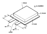
図1、図2、図3にそれぞれ本発明による非水電解質電池11の実施形態例の外観斜視図を示す。これら図1〜図3を参照して本発明による非水電解質電池を説明するが、本発明による非水電解質電池は、このような実施形態例に限定されるものではない。
【0013】
この非水電解質電池11は、上述各電池を構成する電池本体、すなわち素電池1が、ラミネートフィルムから成る外装体2内に密着封入されて成り、この封着部3から、素電池1の一方を正極とし、他方を負極とする端子リード4aおよび4bの遊端が導出された構成を有する。
【0014】
そして、本発明による非水電解質電池11は、正負両極の端子リードの長さLaおよびLbを異ならしめる。すなわち、La≠Lbとする。すなわち、例えば図1に示すように、一方の端子リード4a、例えば正極端子リードの長さLaを、他方の端子リード4b、例えば負極端子リードの長さLbより長く、すなわちLa>Lbとする。
この長さの差La−Lbは、例えば目視的に、両者の長さの相違をを容易に判知できる程度の差の、1mm以上に、そして好ましくは前述したように、15mm以下とする。
【0015】
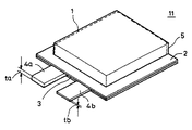
また、本発明は、正負両極の端子リードの幅WaおよびWbを異ならしめるすなわち、Wa≠Wbとする。すなわち、例えば図2に示すように、一方の端子リード4a、例えば正極端子リードの幅Waを、他方の端子リード4b、例えば負極端子リードの幅Wbより大に、すなわちWa>Wbとする。
この幅の差Wa−Wbは、例えば目視的に、両者の幅の相違をを容易に判知できる程度の差の、0.5mm以上に、そして好ましくは前述したように8mm以下とする。
【0016】
更にまた、本発明は、正負両極の端子リードの厚さtaおよびtbを異ならしめる。すなわち、ta≠tbとする。すなわち、例えば図3に示すように、一方の端子リード4a、例えば正極端子リードの厚さtaを、他方の端子リード4b、例えば負極端子リードの厚さtbより大に、すなわちta>tbとする。
この厚さの差ta−tbは、例えば目視的に、両者の幅の相違をを容易に判知できる程度の差の、50μm以上に、そして好ましくは前述したように280μm以下とする。
【0017】
また、ある場合は、上述した長さの相違、幅の相違、厚さの相違を、同時に2以上相違させることもできる。
また、必要に応じて、各端子リード4aおよび4bの導出基部に、正極、負極を表示する例えば“+”、“−”を、印字させることもできる。
【0018】
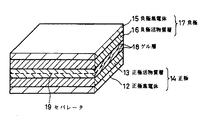
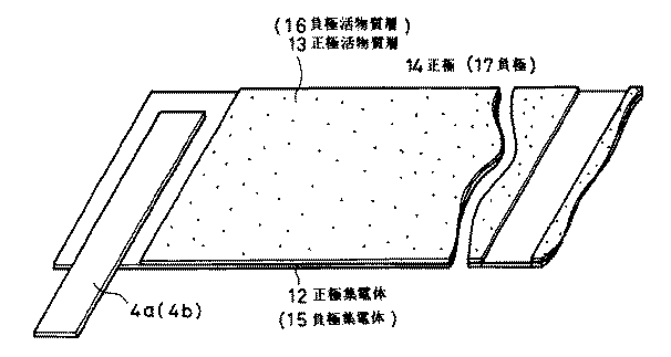
素電池1は、例えば図4に示すように、正極集電体12に、正極活物質層13が被着された正極14と、負極集電体15に、負極活物質層16が被着された負極17とを有して成る。
そして、その正極14と負極17とが、それぞれ正極活物質13と負極活物質層16が塗布された側の主面同士を、電解液を含有するゲル層18を介して直接的にあるいはセパレータ19を介して重ね合わせられた構成とすることができる。
【0019】
正極14および負極17は、それぞれ図5に概略斜視図を示すように、先ず、長尺状の原反として構成される。
正極集電体12は、例えばAl箔による長尺体によって構成され、その片面もしくは両面に、正極活物質13が塗布される。
一方、負極集電体15は、例えばCu箔による長尺体によって構成され、その片面もしくは両面に、負極活物質層16が塗布される。
【0020】
これら正極14および負極17の各正極集電体12および負極集電体15には、それぞれ端子リード4a、4bが、各集電体12、15の長手方向と直交する方向に各遊端が各集電体12、15の側縁から導出されて溶接される。
これら端子リード4aおよび4bは、最終的に形成する幅、厚さに形成される。
【0021】
上述した正極活物質層13および負極活物質層16は、端子リード4aおよび4bの配置部以外に塗布される。
また、正極活物質層13および負極活物質層16上に、それぞれ図4のゲル層18が被着形成される。
このゲル層18は、樹脂とその樹脂を膨潤させる溶媒と電解質から構成できる。
【0022】
これら正極および負極を構成する原反は、それぞれ裁断されて、正極14および負極17が構成され、これらが、両活物質層13および16間に両活物質層13および16の物理的接触を避けるために図4に示すように、セパレータ19を介して重ね合わされ、両端子リード4a、および4bを平行に配置させる状態で扁平状に巻回して、図6に示すように、中心部から両端子リード4aおよび4bが、平行に導出された素電池1を構成する。
【0023】
端子リード4aおよび4bは、素電池1からの導出部において、素電池1の端子導出端面に沿って屈曲され、更にその遊端が、扁平型の素電池1の一方の面に沿ってクランク状に折り曲げられる。
【0024】
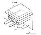
一方、図6に示すように、素電池1の外形状に対応する内形状を有する突出部5が、いわゆる深絞りによって形成されたラミネートフィルム6が用意され、この突出部5内に、素電子1を収容し、素電池1をラミネートフィルム6によって被覆7する。このため、ラミネートフィルム6は、矢印aに示すように、素電池1の端子リード4aおよび4bの導出部とは反対側の後端面において、この後端面に沿って折り曲げ、この折り曲げによる折り返し部によって、素電池1が収容された突出部5の底部開口部が閉蓋されるようにする。そして、この状態で、突出部5の3辺に設けられたフランジ部と、上述した折り曲げによる折り返し部の3辺とが衝合されるようにし、この衝合部において、熱圧着によって封着されるようにする。
このとき、その封着部3から、気密的に端子リード4aおよび4bの遊端が外部に導出されるようになされる。
そして、これら端子リードは、所要の長さに切断される。
【0025】
このようにして、本発明による非水電解質電池が構成されるものであるが、本発明電池においても、両端子リード4aおよび4bの基部側に、正極および負極のマーク例えば“+”“−”のマークを印字することができる。
【0026】
上述の正極活物質は、例えばアルカリ金属を含有する遷移金属とのカルコゲン化合物、この中では特にアルカリ金属と遷移金属との酸化物を用いることができる、化合物の結晶構造として層状化合物やスピネル型化合物がよく用いられる。上記層状化合物の一般式として、AX M′1-y My O2 (x,yは原子比)で表わされる化合物を用いることができる。
ここでAは、Li,Na,Kから選ばれる1種、xおよびyは、0.5≦x1.1、0<y<1である。また、M’,M”は、第1の元素としては、具体的には、Fe,Co,Ni,Mn,Cu,Zn,Cr,V,Tiからなる群のうちの少なくとも1種以上を含有することが好ましく、第2の元素としては、具体的には、Fe,Co,Mn,Cu,Zn,Al,Sn,B,Ga,Cr,V,Ti,Mg,CaおよびSrからなる群のうちの少なくとも1より好ましい。
【0027】
正極活物質は、正極には、スピネル型化合物、正極活物質として一般式LiXMn2-y M′y O4 (但し、x,yは、0.9≦x、0.01≦y≦0.5であり、M′は、Fe,Co,Ni,Cu,Zn,Al,Sn,Cr,V,Ti,Mg,Ca,Sr,B,Ga,In,Si,Geのちの一つまたは複数とする。)で表わされるリチウム・マンガン複合酸化物と、一般式LiNi1-z M″z O2 (但し、zは、0.01≦x≦0.5であり、M″は、Fe,Co,Mn,Cu,Zn,Al,Sn,Cr,V,Ti,Mg,Ca,Sr,B,Ga,In,Si,Geのうちの一つ、または複数とする。)で表わされるリチウム・ニッケル複合酸化物とを含む混合物よりなる正極活物質を用いる。
【0028】
負極活物質材料は、例えばリチウムを吸蔵・離脱可能な負極材料、例えば、リチウムと合金あるいは化合物を形成可能な金属あるいは半導体、またはこれらの合金あるいは化合物が挙げられる。
これら金属、合金あるいは化合物は、例えば、化学式Ds Et Liu で表わされるものである。この化学式において、Dはリチウムと合金あるいは化合物を形成可能な金属元素および半導体元素のうちの少なくとも1種を表わし、EはリチウムおよびD以外の金属元素および半導体元素のうち少なくとも1種を表わす。また、s、tおよびuの値は、それぞれs>0、t≧0、u≧0である。
中でも、リチウムと合金あるいは化合物を形成可能な金属元素あるいは半導体元素としては、4B族の金属元素あるいは半導体元素が好ましく、特に好ましくはSiあるいはSnであり、最も好ましくはSiである。これらの合金あるいは化合物も好ましく、具体的には、SiB4 ,SiB6 ,Mg2 Si,Mg2 Sn,Ni2 Si,TiSi2 ,MoSi2 ,CoSi2 ,NiSi2 ,CaSi2 ,CrSi2 ,Cu5 Si,FeSi2 ,MnSi2 ,NbSi2 ,TaSi2 ,VSi2 ,WSi2 あるいはZnSi2 などが挙げられる。
【0029】
また、リチウムを吸蔵・離脱可能な負極材料としては、また、炭素材料、金属酸化物あるいは高分子材料なども挙げられる。炭素材料としては、例えば、難黒鉛化性炭素、人造黒鉛、コークス類、グラファイト類、ガラス状炭素類、有機高分子化合物焼成体、炭素繊維、活性炭あるいはカーボンブラック類などが挙げられる。
このうち、コークス類には、ピッチコークス、ニードルコークスあるいは石油コークスなどがあり、有機高分子化合物焼成体というのは、フェノール類やフラン類などの高分子材料を適当な温度で焼成して炭素化したものをいう。また、金属酸化物としては、酸化鉄、酸化ルテニウム、酸化モリブデンあるいは酸化スズなどが挙げられ、高分子材料としてはポリアセチレンあるいはポリピロールなどが挙げられる。
【0030】
非水電解質としては、非水溶媒や、固体電解質や、高分子電解質、や高分子化合物に電解質を混合ないしは溶解させた固体状もしくはゲル状電解質等を用いることができる、非水溶媒として、例えば、エチレンカーボネート、プロピレンカーボネート、ブチレンカーボネート、ビニレンカーボネート、γ−ブチルラクトン、γ−バレロラクトン等の環状エステル化合物や、ジエトキシエタン、テトラヒドフラン、2−メチルテトラヒドロフラン、1,3−ジオキサン等のエーテル化合物や、酢酸メチル、プロピレン酸メチル等の、鎖状エステル化合物や、ジメチルカーボネート、ジエチルカーボネート、エチルメチルカーボネート等の鎖状カーボネート、あるいは2,4−ジフルオロアニソール、2,6−ジフルオロアニソール、4−ブロモベラトロール等を単独若しくは2種類以上の混合溶媒として使用することができる。
【0031】
ゲル状電解質に用いられる高分子材料として ゲル状電解質に用いられる高分子材料としては、例えば、ポリアクリロニトリルおよびポリアクリロニトリルの共重合体を使用することができる。共重合モノマー(ビニル系モノマー)としては、例えば酢酸ビニル、メタクリル酸メチル、メタクリル酸ブチル、アクリル酸メチル、アクリル酸ブチル、イタコン酸、水素化メチルアクリレート、水素化エチルアクリレート、アクリルアミド、塩化ビニル、フッ化ビニリデン、塩化ビニリデン等を挙げることができる。さらに、アクリロニトリルブタジエンゴム、アクリロニトリルブタジエンスチレン樹脂、アクリロニトリル塩化ポリエチレンプロピレンジエンスチレン樹脂、アクリロニトリル塩化ビニル樹脂、アクリロニトリルメタアクリレート樹脂、アクリロニトリルアクリレート樹脂等を使用することができる。
【0032】
また、ゲル状電解質に用いられる高分子材料として、ポリエチレンオキサイドおよびポリエチレンオキサイドの共重合体を使用することができる。共重合モノマーとしては、例えばポリプロピレンオキサイド、メタクリル酸メチル、メタクリル酸ブチル、アクリル酸メチル、アクリル酸ブチル等を挙げることができる。
【0033】
更に、ゲル状電解質に用いられる高分子材料として、ポリフッ化ビニリデンおよびポリフッ化ビニリデンの共重合体を使用することができ、共重合体モノマーとしては、例えば、ヘキサフルオロプロピレンやテトラフルオロエチレン等を挙げることができる。
なお、ゲル状電解質に用いられる高分子材料としては、これらを単独または2種類以上混合して使用することができる。
【0034】
ゲル状電解質層を形成するには、非水溶媒として、例えば、エチレンカーボネート、プロピレンカーボネート、ブチレンカーボネート、ビニレンカーボネート、γ−ブチルラクトン、γ−バレロラクトン等の環状エステル化合物や、ジエトキシエタン、テトラヒドロフラン、2−メチルテトラヒドロフラン、1,3−ジオキサン等のエーテル化合物や、酢酸メチル、プロピレン酸メチル等の、鎖状エステル化合物や、ジメチルカーボネート、ジエチルカーボネート、エチルメチルカーボネート等の鎖状カーボネート、あるいは2,4−ジフルオロアニソール、2,6−ジフルオロアニソール、4−ブロモベラトロール等を単独若しくは2種類以上の混合媒体として使用することができる。
【0035】
また、ゲル状電解質層においては、ゲル状電解質としてポリフッ化ビニリデンを使用する場合に、ポリヘキサフルオロプロピレン、ポリ四フッ化エチレン等が共重合された多元系高分子からなるゲル状電解質を用いて形成されていることが好ましい。
さらに好ましくは、ポリフッ化ビニリデンおよびポリヘキサフルオロプロピレンとの共重合体からなるゲル状電解質を用いて形成されていることが好ましい。これにより、より機械的強度の高いゲル状電解質を得ることができる。
【0036】
電解質塩として、例えば、LiPF6 、LiAsF6 、LiBF4 、LiClO4 、LiCF3 SO3 、LiN(CnF2n+1SO2 )2 、LiC4 F9 SO3 等のリチウム塩を単独若しくは2種類以上混合して使用することができる。
なお、電解質塩の添加量は、良好なイオン伝導度が得られるようにゲル状電解質中の非水電解液におけるモル濃度が0.8〜2.0mol/lなるように調製することが好ましい。
【0037】
フィルム状外装体1としては以下のものを挙げることができる。
ラミネートフィルムの構造としては、例えば下記に示される材料を使用することができる。ここで、使用するプラスチック材料として、次の略称を使う。
すなわち、ポリエチレンテレフタレート:PET、溶融ポリプロピレン:PP、無延伸ポリプロピレン:CPP、ポリエチレン:PE、低密度ポリエチレン:LDPE、高密度ポリエチレン:HDPE、直鎖状低密度ポリエチレン:LLDPE、ナイロン:Nyである。また、耐透湿性のバリア膜として用いる金属材料のアルミニウムにALの略称を用いる。
最も一般的な構成は、外装層/金属膜/シーラント層であり、PET/AL/PEである。
また、この組み合わせばかりでなく、以下に示すような他の一般的なラミネートフィルムの構成を採用することができる。
すなわち、外装層/金属膜/シーラント層として、Ny/AL/CPP、PET/AL/CPP、PET/AL/PET/CPP、PET/Ny/AL/CPP、PET/Ny/AL/Ny/CPP、PET/Ny/AL/Ny/PE、Ny/PE/AL/LLDPE、PET/PE/AL/PET/LDPE、またはPET/Ny/AL/LDPE/CPPとすることができる。なお、金属膜としてはAL以外の金属を採用することができることは勿論である。
【0038】
次に、本発明による非水電解質電池について、具体的実施例を挙げて説明する。
〔実施例1〕
長尺状正極の作製:
正極活物質として、LiCoO2 85重量部、人造黒鉛粉末5重量部、カーボンブラック5重量部とを充分に混練した後、N−メチル−2−ピロリドンに溶かしたポリ弗化ビニリデン(PVdF)を固形分として5重量部となるように加え、インク状の正極スラリーを作製した。
【0039】
この正極スラリーを、幅480ミリ、厚さ20μmのAl箔による正極集電体上にピッチ約500mmで、両面に、間欠的に塗布した。ピッチ間においては、約30mmの間隔に渡って正極スラリーが塗布されず、Al箔による正極集電体の露出部を形成した。このようにして得た正極原反に対し、乾燥処理を行って後、ローラープレス機によって圧延し、この圧延後に、正極原反を幅60ミリに裁断し、8本の長尺状正極を形成し、リールに巻き取り、真空乾燥処理した。
【0040】
更に、この長尺正極を、巻きほどき、前述した正極スラリーの塗布がなされず正極集電体の金属箔が露出した部分に、幅10mm、長さ70mm、厚さ300μmのAl端子リードを、その遊端が、正極集電体の側縁から25mm以上突出導出するように、超音波溶接した。
その後、幅19mmのポリイミドテープによる絶縁材を、上述した端子リードが溶接された正極集電体の金属箔の露出部の表裏面に貼り付けた。このポリイミドテープは、集電体の端縁から付き出した端子リードに2mm以上差しかかるように貼り付けた。
上述した工程は連続的に行って、長尺状の正極を形成した。そして、この長尺状の正極を再びリールに巻回した。
【0041】
一方、イオン導電性ポリマー混合溶液を作製した。この混合溶液は、ジメチルカーボネート(DMC)に溶かしたポリ弗化ビニリデン(PVdF)を固形分として20重量部となるように、また、リチウム塩を8重量部となるように加え、これに72重量となるようにエチレンカーボネート(EC)と、プロピレンカーボネート(PC)とを加え、保温しながら撹拌して作製した。
【0042】
この混合液を、ホットメルトアプリケータを用いて、上述の正極電極の両面に、連続的に塗工した。このように塗工されたイオン伝導性ポリマー混合溶液を、乾燥して活物質内部の空隙に含浸させるとともに、低沸点溶媒であるDMCを蒸発させてゴム状のゲルポリマー膜によるゲル層を形成した。
このイオン導電性ポリマー溶液は、長尺状の正極上に、連続的に塗工する。
このようにして、端子リード付きの長尺の正極電極を形成し、これを再びリール上に巻き取った。
【0043】
長尺状負極の作製:
負極活物質として、粒子径が5〜25μmの天然黒鉛90重量部(層間距離3.35Å)、N−メチル−2−ピロリドンに溶かしたPVdFを固形分として10重量部になるように加え、インク状の負極スラリーを作製した。
この負極スラリーを、幅520mm、厚さ15μmのCu箔による負極集電体上に、ピッチ約550mmで、両面に、間欠的に塗布し、ピッチ間において、約30mmの間隔に渡って負極スラリーが塗布されず、Cu箔による負極集電体の露出部を形成して、負極原反を作製した。
この原反を乾燥し、その後ローラープレス機により圧延した。圧延後、負極原反を幅65mmに裁断し、8本の長尺の電極をリール上に巻き取り、真空乾燥処理した。
【0044】
この電極を、巻きほどき、その負極集電体の露出部に、幅10mm、長さ70ミリ、厚さ300μmのNi箔による端子リードを、その遊端が、負極集電体の側縁から25mm以上突出導出されるように、超音波溶接した。
その後、幅19mmのポリミドテープによる絶縁材を、上述した端子リードが溶接された負極集電体の金属箔の露出部の表裏面に貼り付けた。このポリイミドテープは、集電体の端縁から付き出した端子リードに2mm以上差しかかるように貼り付けた。
上述した工程は連続的に行って、長尺状の負極を形成した。そして、この長尺状の負極を再び、リールに巻回した。
【0045】
一方、イオン伝導性ポリマー混合溶液を前述した正極におけると同様にして作製した。
この混合液を、ホットメルトアプリケータを用いて、負極の両面に、塗工した。このように塗工されたイオン伝導性ポリマー混合溶液を、乾燥して活物質内部の空隙に含浸させるとともに、低沸点溶媒であるDMCを蒸発させてゴム状のゲルポリマー膜によるゲル層を形成した。
このイオン導電性ポリマー溶液は、長尺状の負極上に、連続的に塗工する。
このようにして、端子リード付きの長尺の負極を形成し、これを再びリール上に巻き取った。
【0046】
素電池の作製:
上述のようにして作製した正極および負極によって素電池1を得た。
すなわち、それぞれ上述したイオン導電性ポリマーで覆われた端子リードの導出がなされた長尺負極と、長尺正極とを、それぞれの端子リードが平行するように、セパレータを介して、楕円状にすなわち扁平形状に巻回して素電池1を作製した。
【0047】
この素電池1を、図6で説明したように、素電池1の外形に対応する内形状を有する突出部5内に収容して、素電池1を包み込むように折り曲げ被覆して、その周辺の3辺を、それぞれヒートシール機および真空ヒートシール機によって熱封着した。
このとき、その封着部3から、素電池1の端子リード4a,4bの遊端が外部に気密的に導出されるようにし、これら端子リードは、所要の長さに切断した。この例では、両端子リードを、外装体からそれぞれ20mmの長さに導出するように構成し、その後正極側の端子リードの長さが、負極側の端子リードより2mm長くなるように、負極端子リードを切断して、負極端子リードの導出長を18mmとした。
また、端子リード相互の間隔は、60mmとした。
【0048】
実施例1においては、正極端子リードを、負極端子リードより2mm長くした非水電解質電池を構成した場合であるが、この端子リード相互の長さの相違を変化させた場合の実施例と比較例を挙げる。
【0049】
〔実施例2〕
この実施例においては、実施例1と同様にして非水電解質電池を作製したが、最終的に、正極端子リードの長さを、負極端子リードの長さより1.0mm長く作製した。
【0050】
〔比較例1〕
この例では、実施例1と同様にして非水電解質電池を作製したが、最終的に、正極端子リードの長さを、負極端子リードの長さより0.5mm長く作製した。
【0051】
〔実施例3〕
この実施例においては、実施例1と同様にして非水電解質電池を作製したが、最終的に、正極端子リードの長さを、負極端子リードの長さより2.0mm短く作製した。
【0052】
〔実施例4〕
この実施例においては、実施例1と同様にして非水電解質電池を作製したが、最終的に、正極端子リードの長さを、負極端子リードの長さより1.0mm短く作製した。
【0053】
〔比較例2〕
この例では、実施例1と同様にして非水電解質電池を作製したが、最終的正極端子リードの長さを、負極端子リードの長さより0.5mm短く作製した。
【0054】
〔比較例3〕
この例では、実施例1と同様にして非水電解質電池を作製したが、最終的に、正極端子リードの長さと、負極端子リードの長さとを、共に20mmとした。
【0055】
〔実施例5〕
この実施例においては、比較例3と同様にして非水電解質電池を作製したが、正極端子リードの幅を、負極端子リードの幅より1.0mm広く作製した。この場合、負極端子リードの幅は9mmとした。
【0056】
〔実施例6〕
この実施例においては、比較例3と同様にして非水電解質電池を作製したが、正極端子リードの幅を、負極端子リードの幅より0.5mm広く作製した。
【0057】
〔比較例4〕
この例においては、比較例3と同様にして非水電解質電池を作製したが、正極端子リードの幅を、負極端子リードの幅より0.25mm広く作製した。
【0058】
〔実施例7〕
この実施例においては、比較例3と同様にして非水電解質電池を作製したが、負極端子リードの幅を、正極端子リードの幅より1.0mm広く作製した。この場合、正極端子リードの幅は9mmとした。
【0059】
〔実施例8〕
この実施例においては、比較例3と同様にして非水電解質電池を作製したが、負極端子リードの幅を、正極端子リードの幅より0.5mm広く作製した。
【0060】
〔比較例5〕
この例においては、比較例3と同様にして非水電解質電池を作製したが、負極端子リードの幅を、正極端子リードの幅より0.25mm広く作製した。
【0061】
〔実施例9〕
この実施例においては、比較例3と同様にして非水電解質電池を作製したが、正極端子リードの厚さを、負極端子リードの厚さより100μm厚く作製した。負極端子リードの厚さは、200μmとした。
【0062】
〔実施例10〕
この実施例においては、比較例3と同様にして非水電解質電池を作製したが、正極端子リードの厚さを、負極端子リードの厚さより50μm厚く作製した。
【0063】
〔比較例6〕
この例においては、比較例3と同様にして非水電解質電池を作製したが、正極端子リードの厚さを、負極端子リードの厚さより25μm厚く作製した。
【0064】
〔実施例11〕
この実施例においては、比較例3と同様にして非水電解質電池を作製したが、負極端子リードの厚さを、正極端子リードの厚さより100μm厚く作製した。正極端子リードの厚さは、200μmとした。
【0065】
〔実施例12〕
この実施例においては、比較例3と同様にして非水電解質電池を作製したが、負極端子リードの厚さを、正極端子リードの厚さより50μm厚く作製した。
【0066】
〔比較例7〕
この例においては、比較例3と同様にして非水電解質電池を作製したが、負極端子リードの厚さを、正極端子リードの厚さより25μm厚く作製した。
【0067】
上述した各実施例1〜12、比較例1〜7による各非水電解質電池について、その両端子リードを、それぞれ目視によって、正極端子リードであるか、負極端子リードであるかを、判断する手法をとった半自動生産設備で、パック加工したときの、その正負極端子リードの判断ミスによる不良品の発生率(不良率)の測定結果を、表1〜表3に示す。
【0068】
【表1】
【表2】
【表3】
これらの結果から、非水電解質電池において、正負極端子リードの長さが、互いに1mm以上異なることで、確実に両端子リードの極性判断を正確に行うことができることが確認された。
そして、電池11からの端子リード4aおよび4bの、外装体2からの外部への導出長は、電池11の梱包、溶接時の取り扱い易さからは20mm以下に、また外部回路基板への端子リードの溶接のために必要な面積を考慮すると、その長さは最低限5mm必要となる。このことから、両端子リードの長さの差は、15mm以下とすることが望ましい。つまり、端子リード4aおよび4bの導出部の長さは、5mm〜20mmとされ、両端子リードの導出部の長さの差は、1mm〜15mmとされる。
【0072】
また、両端子リードの幅は、0.5mm以上異なることによって、確実に両端子リードの極性判断を正確に行うことができることが確認された。
しかしながら、外装体2の封着部における密着性、すなわち封着部の信頼性の上からは、その両端子リード4aおよび4bの幅は、小さい方が望ましい。両端子リード4aおよび4bの、回路基板への溶接を考慮すると、その幅は、10mmあれば充分である。そして、素電池1の作製前の、正極および負極への端子リードの溶接の面積を考慮すると、2mm以上必要とすることから、端子リード4aおよび4bの幅は、2mm〜10mmとされ、両端子リード4aおよび4bの幅の差は、0.5mm〜8mmとされる。
【0073】
また、両端子リード4aおよび4bの厚さの差は、50μm以上異なることで、確実に両端子リードの極性判断を正確に行うことができることが確認された。
しかしながら、これら端子リード4aおよび4bの厚さは、素電池1の作製前の正極および負極への端子リードの溶接部における強度を確保するために、20μm以上を必要とするものであり、片や、外装体2の封着部3の密着性、すなわち封着部の信頼性の上からは、その両端子リード4aおよび4bの厚さは、300μm以下であることが望まれる。そこで、両端子リード4aおよび4bの厚さは20μm〜300μmとされ、両端子リードの差は、50μm〜280μmとされる。
【0074】
また、一般的に、上述した薄型の電池をパック加工するときの回路基板は、6mm〜60mm程度の範囲で電池の“+”,“−”を接続する形状を有していることから、両端子リード4aおよび4b間の間隔は、6mm〜60mmとされる
【0075】
【発明の効果】
上述したように、本発明によれば、非水電解質電池において、例えば電池パックを構成する場合等において、その正極端子リードと、負極端子リード相互の構成、数値特定を行ったことによって確実に判断することができる構成、数値特定によって例えば電池パックの製造作業を能率的に、また、これら正極端子リードと、負極端子リードとの取り違えによる不良品の発生率を低めることができることから、生産性の向上、歩留りの向上を図ることができ、ひいては、コストの低減化を図ることができるものである。
【図面の簡単な説明】
【図1】本発明による非水電解質電池の一例の斜視図である。
【図2】本発明による非水電解質電池の他の一例の斜視図である。
【図3】本発明による非水電解質電池の更に他の一例の斜視図である。
【図4】本発明による非水電解質電池の素電池の一例の一部の一部を破断面とした斜視図である。
【図5】本発明による非水電解質電池の素電池の一例の要部の分解展開図である。
【図6】本発明による非水電解質電池の素電池の一例の外装体の展開状態を示す斜視図である。
【符号の説明】
1・・・素電池、2・・・外装体、3・・・封着部、4a,4b・・・端子リード部、5・・・外装体の突起部、6・・・ラミネート、11・・・電池、12・・・正極集電体、13・・・正極活物質、14・・・正極、15・・・負極集電体、16・・・負極活物質、17・・・負極[0001]
BACKGROUND OF THE INVENTION
The present invention relates to a non-aqueous electrolyte battery, particularly a non-aqueous electrolyte battery using a so-called laminate battery in which a battery element is accommodated in an exterior body made of a laminate film.
[0002]
[Prior art]
Square batteries that use laminate film as an outer package are attracting attention as batteries with flexibility and high energy density that can be made thinner and lighter than batteries using iron battery cans and aluminum battery cans. Yes.
A battery having this laminate film as an outer package is characterized in that the positive electrode terminal lead and the negative electrode terminal lead are sandwiched between the heat-welded portions of the laminate film, and the outer end is led out from the laminate film, that is, the outer package. Thus, an electrode terminal is configured.
In this type of battery, the length of the protruding lead-out portion of the terminal lead from the aforementioned exterior body is selected to be the same for the positive terminal lead and the negative terminal lead.
Then, at the base position of the external lead-out portion of these terminal leads, each mark of + mark and − mark that determines whether they are positive terminal leads or negative terminal leads is printed by inkjet.
[0003]
However, such positive and negative discrimination marks “+” and “−” are usually attached only to one side of the battery. This is based on the idea that it is only necessary to determine whether each lead is a positive electrode or a negative electrode. That is, it is based on the premise that the battery model, size, and lot are specified and the direction of the battery is unified. However, when the surface on which the above-described positive and negative mark marks are not printed is, for example, upward and difficult to observe, there is a problem that the two cannot be distinguished from each other.
[0004]
In addition, since the negative electrode terminal lead and the positive electrode terminal lead are often made of nickel-based metal and aluminum-based metal, respectively, are they negative terminals visually by themselves, that is, depending on the difference between the constituent materials of the two? It is difficult to determine whether it is a positive terminal lead.
On the other hand, such a laminated battery is usually packed as a battery pack, for example, accommodated in a case. Since this laminated battery has a thin outer thickness and is flexible, generally, all of the battery pack processing is performed. Automation is difficult.
For this reason, this pack processing is performed by so-called semi-automation by manual operation.
[0005]
When such a manual is passed, it takes time to determine the negative electrode and the positive electrode of the terminal lead described above, or an error in the determination impedes the productivity, causes the generation of defective products, and decreases the yield. .
[0006]
[Problems to be solved by the invention]
The present invention provides a nonaqueous electrolyte battery in which the above-described determination of the negative electrode and the positive electrode of the terminal lead of the nonaqueous electrolyte battery can be performed easily and reliably.
[0007]
[Means for Solving the Problems]
In the non-aqueous electrolyte battery according to the present invention, the unit cell is tightly sealed in an outer package made of a laminate film, and the positive electrode terminal lead and the negative electrode terminal lead of the unit cell are juxtaposed from the sealing portion by heat fusion of the laminate film. It is a nonaqueous electrolyte battery led out to the outside, and the lead-out lengths of the positive electrode terminal lead and the negative electrode terminal lead from the exterior body are different from each other by 1 mm or more. As will be described later, the difference in the derived length is preferably different by 15 mm or less for the convenience of actual handling.
[0008]
Similarly, in the nonaqueous electrolyte battery according to the present invention, the unit cell is tightly sealed in the outer package made of the laminate film, and the positive electrode terminal lead and the negative electrode terminal of the unit cell are sealed from the heat-sealed portion of the laminate film. A non-aqueous electrolyte battery in which the leads are arranged in parallel and led to the outside, and the widths of the positive electrode terminal lead and the negative electrode terminal lead at the lead-out portion from the exterior body are different from each other by 0.5 mm or more. . As will be described later, the difference in width is preferably set to be different by 8 mm or less for the convenience of actual handling.
[0009]
Furthermore, in the nonaqueous electrolyte battery according to the present invention, the unit cell is tightly sealed in the outer package made of a laminate film, and the positive electrode terminal lead and the negative electrode terminal lead of the unit cell are juxtaposed from the sealed portion by heat fusion of the laminate film. Thus, the nonaqueous electrolyte battery is led out to the outside, and the thickness of the positive terminal lead and the negative terminal lead at the lead-out portion from the outer package is different by 50 μm or more. It is preferable that the difference in thickness be 280 μm or less as described later.
[0010]
As described above, according to the configuration of the present invention, the lead lengths of the negative electrode and positive electrode terminal leads are made different by 1 mm or more, so that the polarity of these terminal leads can be immediately determined without error. It was confirmed that it was possible.
Further, according to the configuration of the present invention, the widths of the negative electrode and positive electrode both terminal leads are made different by 0.5 mm or more, so that it is possible to immediately determine which polarity the both terminal leads are without error. Confirmed that it can.
Furthermore, according to the configuration of the present invention, the negative electrode and the positive electrode both terminal leads are made different in thickness by 50 μm or more so that the polarity of both terminal leads can be immediately determined without error. It is confirmed that can be done.
[0011]
Further, in the present invention, the bipolar terminal leads may be configured to be different in the derived length, in different widths, or in different thicknesses, and two or more configurations are adopted at the same time. In this way, by using two or more configurations, it is possible to perform an immediate disconnection more accurately.
[0012]
DETAILED DESCRIPTION OF THE INVENTION
The nonaqueous electrolyte battery according to the present invention is, for example, a solid electrolyte battery, a gel electrolyte battery, a liquid electrolyte battery, or the like.
FIG. 1, FIG. 2 and FIG. 3 are external perspective views of embodiments of the
[0013]
The
[0014]
In the
This length difference La-Lb is, for example, not less than 1 mm, and preferably not more than 15 mm, as described above, so that the difference between the lengths can be easily recognized visually.
[0015]
In the present invention, the widths Wa and Wb of the positive and negative terminal leads are made different, that is, Wa ≠ Wb. That is, for example, as shown in FIG. 2, the width Wa of one
The width difference Wa−Wb is set to 0.5 mm or more, and preferably 8 mm or less, as described above, for example, so that the difference between the widths can be easily recognized visually.
[0016]
Furthermore, the present invention makes the thicknesses ta and tb of the positive and negative terminal leads different. That is, ta ≠ tb. That is, for example, as shown in FIG. 3, the thickness ta of one
The thickness difference ta−tb is, for example, 50 μm or more, and preferably 280 μm or less, as described above, so that the difference in width between the two can be easily recognized visually.
[0017]
Further, in some cases, two or more of the above-described difference in length, difference in width, and difference in thickness can be made different.
If necessary, for example, “+” and “−” indicating the positive electrode and the negative electrode can be printed on the lead-out bases of the terminal leads 4a and 4b.
[0018]
For example, as shown in FIG. 4, the unit cell 1 includes a positive electrode 14 in which a positive electrode active material layer 13 is applied to a positive electrode current collector 12, and a negative electrode active material layer 16 that is applied to a negative electrode current collector 15. And a negative electrode 17.
Then, the positive electrode 14 and the negative electrode 17 are directly connected to the main surfaces on the side where the positive electrode active material 13 and the negative electrode active material layer 16 are applied, respectively, via the gel layer 18 containing the electrolytic solution, or the
[0019]
First, each of the positive electrode 14 and the negative electrode 17 is configured as a long original as shown in a schematic perspective view in FIG.
The positive electrode current collector 12 is constituted by a long body made of, for example, an Al foil, and a positive electrode active material 13 is applied to one side or both sides thereof.
On the other hand, the negative electrode current collector 15 is formed of a long body made of, for example, Cu foil, and the negative electrode active material layer 16 is applied to one surface or both surfaces thereof.
[0020]
Each of the positive electrode current collector 12 and the negative electrode current collector 15 of the positive electrode 14 and the negative electrode 17 has terminal leads 4a and 4b, and each free end is in a direction perpendicular to the longitudinal direction of the current collectors 12 and 15, respectively. The current collectors 12 and 15 are led out from the side edges and welded.
These terminal leads 4a and 4b are formed to have a width and thickness that are finally formed.
[0021]
The positive electrode active material layer 13 and the negative electrode active material layer 16 described above are applied to portions other than the arrangement portions of the terminal leads 4a and 4b.
4 is deposited on the positive electrode active material layer 13 and the negative electrode active material layer 16, respectively.
The gel layer 18 can be composed of a resin, a solvent that swells the resin, and an electrolyte.
[0022]
The raw materials constituting the positive electrode and the negative electrode are respectively cut to form the positive electrode 14 and the negative electrode 17, which avoid physical contact between the active material layers 13 and 16 between the active material layers 13 and 16. Therefore, as shown in FIG. 4, the
[0023]
The terminal leads 4a and 4b are bent along the terminal lead-out end surface of the unit cell 1 at the lead-out portion from the unit cell 1, and the free end thereof is crank-shaped along one surface of the flat unit cell 1. Can be folded.
[0024]
On the other hand, as shown in FIG. 6, a
At this time, the free ends of the terminal leads 4a and 4b are led out from the sealing
These terminal leads are cut to a required length.
[0025]
In this way, the nonaqueous electrolyte battery according to the present invention is constituted. Also in the battery of the present invention, positive and negative marks such as “+” and “−” are formed on the base side of both terminal leads 4a and 4b. Can be printed.
[0026]
The positive electrode active material described above may be, for example, a chalcogen compound with a transition metal containing an alkali metal, among which an oxide of an alkali metal and a transition metal can be used, and a layered compound or spinel compound as the crystal structure of the compound Is often used. As a general formula of the layered compound, A X M ' 1-y M y O 2 A compound represented by (x and y are atomic ratios) can be used.
Here, A is one selected from Li, Na, and K, and x and y are 0.5 ≦ x1.1 and 0 <y <1. Further, M ′, M ″, as the first element, specifically contains at least one or more members selected from the group consisting of Fe, Co, Ni, Mn, Cu, Zn, Cr, V, and Ti. Preferably, the second element is specifically selected from the group consisting of Fe, Co, Mn, Cu, Zn, Al, Sn, B, Ga, Cr, V, Ti, Mg, Ca and Sr. More preferred than at least one of them.
[0027]
The positive electrode active material is a spinel compound as the positive electrode, and the general formula LiXMn as the positive electrode active material. 2-y M ' y O Four (However, x and y are 0.9 ≦ x and 0.01 ≦ y ≦ 0.5, and M ′ is Fe, Co, Ni, Cu, Zn, Al, Sn, Cr, V, Ti, Lithium-manganese composite oxide represented by Mg, Ca, Sr, B, Ga, In, Si, or Ge)) and a general formula LiNi 1-z M ″ z O 2 (However, z is 0.01 ≦ x ≦ 0.5, and M ″ is Fe, Co, Mn, Cu, Zn, Al, Sn, Cr, V, Ti, Mg, Ca, Sr, B, A positive electrode active material made of a mixture containing a lithium / nickel composite oxide represented by one or more of Ga, In, Si, and Ge is used.
[0028]
Examples of the negative electrode active material include a negative electrode material capable of inserting and extracting lithium, for example, a metal or semiconductor capable of forming an alloy or compound with lithium, or an alloy or compound thereof.
These metals, alloys or compounds can be represented, for example, by chemical formula D s E t Li u It is represented by In this chemical formula, D represents at least one of a metal element and a semiconductor element capable of forming an alloy or compound with lithium, and E represents at least one of a metal element and a semiconductor element other than lithium and D. The values of s, t, and u are s> 0, t ≧ 0, and u ≧ 0, respectively.
Among them, the metal element or semiconductor element capable of forming an alloy or compound with lithium is preferably a group 4B metal element or semiconductor element, particularly preferably Si or Sn, and most preferably Si. These alloys or compounds are also preferable, specifically, SiB Four , SiB 6 , Mg 2 Si, Mg 2 Sn, Ni 2 Si, TiSi 2 , MoSi 2 , CoSi 2 , NiSi 2 , CaSi 2 , CrSi 2 , Cu Five Si, FeSi 2 , MnSi 2 , NbSi 2 , TaSi 2 , VSi 2 , WSi 2 Or ZnSi 2 Etc.
[0029]
In addition, examples of the negative electrode material capable of inserting and extracting lithium include carbon materials, metal oxides, and polymer materials. Examples of the carbon material include non-graphitizable carbon, artificial graphite, cokes, graphites, glassy carbons, organic polymer compound fired bodies, carbon fibers, activated carbon, and carbon blacks.
Among these, coke includes pitch coke, needle coke and petroleum coke. Organic polymer compound fired bodies are carbonized by firing polymer materials such as phenols and furans at an appropriate temperature. What you did. In addition, examples of the metal oxide include iron oxide, ruthenium oxide, molybdenum oxide, and tin oxide, and examples of the polymer material include polyacetylene and polypyrrole.
[0030]
As the non-aqueous electrolyte, a non-aqueous solvent, a solid electrolyte, a polymer electrolyte, a solid or gel electrolyte in which an electrolyte is mixed or dissolved, and the like can be used. , Cyclic ester compounds such as ethylene carbonate, propylene carbonate, butylene carbonate, vinylene carbonate, γ-butyllactone, γ-valerolactone, and ethers such as diethoxyethane, tetrahydrfuran, 2-methyltetrahydrofuran, 1,3-dioxane Compounds, chain ester compounds such as methyl acetate and methyl propylene, chain carbonates such as dimethyl carbonate, diethyl carbonate, and ethyl methyl carbonate, 2,4-difluoroanisole, 2,6-difluoroanisole, 4- Bromobe Latrol or the like can be used alone or as a mixed solvent of two or more.
[0031]
As the polymer material used for the gel electrolyte As the polymer material used for the gel electrolyte, for example, polyacrylonitrile and a copolymer of polyacrylonitrile can be used. Examples of copolymerizable monomers (vinyl monomers) include vinyl acetate, methyl methacrylate, butyl methacrylate, methyl acrylate, butyl acrylate, itaconic acid, hydrogenated methyl acrylate, hydrogenated ethyl acrylate, acrylamide, vinyl chloride, fluorine. And vinylidene chloride and vinylidene chloride. Furthermore, acrylonitrile butadiene rubber, acrylonitrile butadiene styrene resin, acrylonitrile chlorinated polyethylene propylene diene styrene resin, acrylonitrile vinyl chloride resin, acrylonitrile methacrylate resin, acrylonitrile acrylate resin and the like can be used.
[0032]
Moreover, as a polymer material used for the gel electrolyte, polyethylene oxide and a copolymer of polyethylene oxide can be used. Examples of the copolymerization monomer include polypropylene oxide, methyl methacrylate, butyl methacrylate, methyl acrylate, and butyl acrylate.
[0033]
Furthermore, polyvinylidene fluoride and a copolymer of polyvinylidene fluoride can be used as the polymer material used for the gel electrolyte, and examples of the copolymer monomer include hexafluoropropylene and tetrafluoroethylene. be able to.
In addition, as a polymeric material used for gel electrolyte, these can be used individually or in mixture of 2 or more types.
[0034]
In order to form the gel electrolyte layer, as a non-aqueous solvent, for example, cyclic ester compounds such as ethylene carbonate, propylene carbonate, butylene carbonate, vinylene carbonate, γ-butyllactone, γ-valerolactone, diethoxyethane, tetrahydrofuran Ether compounds such as 2-methyltetrahydrofuran and 1,3-dioxane, chain ester compounds such as methyl acetate and methyl propylene acid, chain carbonates such as dimethyl carbonate, diethyl carbonate, and ethyl methyl carbonate; 4-Difluoroanisole, 2,6-difluoroanisole, 4-bromoveratrol and the like can be used alone or as a mixed medium of two or more.
[0035]
In addition, in the gel electrolyte layer, when using polyvinylidene fluoride as the gel electrolyte, a gel electrolyte made of a multi-component polymer in which polyhexafluoropropylene, polytetrafluoroethylene, or the like is copolymerized is used. Preferably it is formed.
More preferably, it is formed using a gel electrolyte made of a copolymer of polyvinylidene fluoride and polyhexafluoropropylene. As a result, a gel electrolyte having higher mechanical strength can be obtained.
[0036]
As an electrolyte salt, for example, LiPF 6 , LiAsF 6 , LiBF Four LiClO Four , LiCF Three SO Three , LiN (CnF 2n + 1 SO 2 ) 2 , LiC Four F 9 SO Three These lithium salts can be used alone or in admixture of two or more.
In addition, it is preferable to adjust the addition amount of electrolyte salt so that the molar concentration in the non-aqueous electrolyte in gel electrolyte may be 0.8-2.0 mol / l so that favorable ionic conductivity may be obtained.
[0037]
Examples of the film-shaped outer package 1 include the following.
As the structure of the laminate film, for example, the following materials can be used. Here, the following abbreviations are used as plastic materials to be used.
That is, polyethylene terephthalate: PET, molten polypropylene: PP, unstretched polypropylene: CPP, polyethylene: PE, low density polyethylene: LDPE, high density polyethylene: HDPE, linear low density polyethylene: LLDPE, nylon: Ny. In addition, the abbreviation AL is used for aluminum, which is a metal material used as a moisture-permeable barrier film.
The most common configuration is an exterior layer / metal film / sealant layer, which is PET / AL / PE.
Moreover, not only this combination but the structure of the other general laminate film as shown below is employable.
That is, as exterior layer / metal film / sealant layer, Ny / AL / CPP, PET / AL / CPP, PET / AL / PET / CPP, PET / Ny / AL / CPP, PET / Ny / AL / Ny / CPP, It can be PET / Ny / AL / Ny / PE, Ny / PE / AL / LLDPE, PET / PE / AL / PET / LDPE, or PET / Ny / AL / LDPE / CPP. Of course, metals other than AL can be used as the metal film.
[0038]
Next, the nonaqueous electrolyte battery according to the present invention will be described with specific examples.
[Example 1]
Production of long positive electrode:
LiCoO as positive electrode active material 2 85 parts by weight, 5 parts by weight of artificial graphite powder, and 5 parts by weight of carbon black are sufficiently kneaded, and then 5 parts by weight of polyvinylidene fluoride (PVdF) dissolved in N-methyl-2-pyrrolidone as a solid content. In addition, an ink-like positive electrode slurry was prepared.
[0039]
This positive electrode slurry was intermittently applied to both surfaces with a pitch of about 500 mm on a positive electrode current collector made of Al foil having a width of 480 mm and a thickness of 20 μm. Between the pitches, the positive electrode slurry was not applied over an interval of about 30 mm, and an exposed portion of the positive electrode current collector was formed of Al foil. The positive electrode raw material thus obtained is dried and then rolled by a roller press. After this rolling, the positive electrode raw material is cut into a width of 60 mm to form eight long positive electrodes. And wound on a reel and vacuum-dried.
[0040]
Further, the long positive electrode is unwound, and the above-described positive electrode slurry is not applied to the exposed portion of the metal foil of the positive electrode current collector, and an Al terminal lead having a width of 10 mm, a length of 70 mm, and a thickness of 300 μm is provided. Ultrasonic welding was carried out so that the free end protruded 25 mm or more from the side edge of the positive electrode current collector.
Thereafter, an insulating material made of polyimide tape having a width of 19 mm was attached to the front and back surfaces of the exposed portion of the metal foil of the positive electrode current collector to which the terminal lead described above was welded. This polyimide tape was affixed so that 2 mm or more might be inserted in the terminal lead sticked out from the edge of the electrical power collector.
The steps described above were performed continuously to form a long positive electrode. And this elongate positive electrode was wound around the reel again.
[0041]
On the other hand, an ion conductive polymer mixed solution was prepared. To this mixed solution, polyvinylidene fluoride (PVdF) dissolved in dimethyl carbonate (DMC) was added to a solid content of 20 parts by weight, and lithium salt was added to 8 parts by weight. Ethylene carbonate (EC) and propylene carbonate (PC) were added so as to be and stirred while keeping warm.
[0042]
This mixed solution was continuously coated on both surfaces of the positive electrode using a hot melt applicator. The ion conductive polymer mixed solution thus applied was dried and impregnated into the voids inside the active material, and the low boiling point solvent DMC was evaporated to form a gel layer with a rubbery gel polymer film. .
This ion conductive polymer solution is continuously applied on the long positive electrode.
In this way, a long positive electrode with terminal leads was formed, and this was again wound on a reel.
[0043]
Production of long negative electrode:
As a negative electrode active material, 90 parts by weight of natural graphite having a particle diameter of 5 to 25 μm (interlayer distance: 3.35 mm), PVdF dissolved in N-methyl-2-pyrrolidone was added to a solid content of 10 parts by weight, and ink was added. A negative electrode slurry was prepared.
This negative electrode slurry was applied intermittently on both sides with a pitch of about 550 mm on a negative electrode current collector made of Cu foil having a width of 520 mm and a thickness of 15 μm, and the negative electrode slurry was spread over an interval of about 30 mm between the pitches. The negative electrode raw material was produced by forming an exposed portion of the negative electrode current collector by Cu foil without coating.
This original fabric was dried and then rolled with a roller press. After rolling, the negative electrode raw material was cut into a width of 65 mm, and eight long electrodes were wound on a reel and vacuum dried.
[0044]
This electrode is unwound, and a terminal lead made of a Ni foil having a width of 10 mm, a length of 70 mm, and a thickness of 300 μm is formed on the exposed portion of the negative electrode current collector, and the free end thereof extends from the side edge of the negative electrode current collector. Ultrasonic welding was performed so that the protrusion was led out by 25 mm or more.
Thereafter, an insulating material made of a polyimide tape having a width of 19 mm was attached to the front and back surfaces of the exposed portion of the metal foil of the negative electrode current collector to which the terminal lead described above was welded. This polyimide tape was affixed so that 2 mm or more might be inserted in the terminal lead sticked out from the edge of the electrical power collector.
The steps described above were performed continuously to form a long negative electrode. And this elongate negative electrode was again wound around the reel.
[0045]
On the other hand, an ion conductive polymer mixed solution was prepared in the same manner as in the positive electrode described above.
This mixed solution was coated on both surfaces of the negative electrode using a hot melt applicator. The ion conductive polymer mixed solution thus applied was dried and impregnated into the voids inside the active material, and the low boiling point solvent DMC was evaporated to form a gel layer with a rubbery gel polymer film. .
This ion conductive polymer solution is continuously applied on the long negative electrode.
In this manner, a long negative electrode with terminal leads was formed, and this was again wound on a reel.
[0046]
Production of unit cell:
A unit cell 1 was obtained from the positive electrode and the negative electrode produced as described above.
That is, the long negative electrode from which the terminal lead covered with the above-described ion conductive polymer was led out, and the long positive electrode, in an elliptical shape through the separator so that the respective terminal leads are parallel to each other, The unit cell 1 was produced by winding in a flat shape.
[0047]
As illustrated in FIG. 6, the unit cell 1 is accommodated in the protruding
At this time, the free ends of the terminal leads 4a and 4b of the unit cell 1 were led out from the sealing
The interval between the terminal leads was 60 mm.
[0048]
In Example 1, a nonaqueous electrolyte battery in which the positive electrode terminal lead was made 2 mm longer than the negative electrode terminal lead was constructed. However, the Example and Comparative Example in which the difference in length between the terminal leads was changed Give up.
[0049]
[Example 2]
In this example, a non-aqueous electrolyte battery was produced in the same manner as in Example 1, but finally, the length of the positive terminal lead was made 1.0 mm longer than the length of the negative terminal lead.
[0050]
[Comparative Example 1]
In this example, a non-aqueous electrolyte battery was produced in the same manner as in Example 1, but finally, the length of the positive terminal lead was made 0.5 mm longer than the length of the negative terminal lead.
[0051]
Example 3
In this example, a non-aqueous electrolyte battery was produced in the same manner as in Example 1. Finally, the length of the positive electrode terminal lead was made 2.0 mm shorter than the length of the negative electrode terminal lead.
[0052]
Example 4
In this example, a non-aqueous electrolyte battery was produced in the same manner as in Example 1, but finally, the length of the positive terminal lead was made shorter by 1.0 mm than the length of the negative terminal lead.
[0053]
[Comparative Example 2]
In this example, a nonaqueous electrolyte battery was produced in the same manner as in Example 1, but the final positive terminal lead length was made 0.5 mm shorter than the negative terminal lead length.
[0054]
[Comparative Example 3]
In this example, a non-aqueous electrolyte battery was produced in the same manner as in Example 1. Finally, the length of the positive terminal lead and the length of the negative terminal lead were both 20 mm.
[0055]
Example 5
In this example, a non-aqueous electrolyte battery was produced in the same manner as in Comparative Example 3, but the positive terminal lead was made wider by 1.0 mm than the negative terminal lead. In this case, the width of the negative terminal lead was 9 mm.
[0056]
Example 6
In this example, a non-aqueous electrolyte battery was produced in the same manner as in Comparative Example 3, but the width of the positive terminal lead was made 0.5 mm wider than the width of the negative terminal lead.
[0057]
[Comparative Example 4]
In this example, a nonaqueous electrolyte battery was produced in the same manner as in Comparative Example 3, but the positive terminal lead was made wider by 0.25 mm than the negative terminal lead.
[0058]
Example 7
In this example, a non-aqueous electrolyte battery was produced in the same manner as in Comparative Example 3, but the width of the negative terminal lead was made 1.0 mm wider than the width of the positive terminal lead. In this case, the width of the positive terminal lead was 9 mm.
[0059]
Example 8
In this example, a non-aqueous electrolyte battery was produced in the same manner as in Comparative Example 3, but the width of the negative terminal lead was made 0.5 mm wider than the width of the positive terminal lead.
[0060]
[Comparative Example 5]
In this example, a non-aqueous electrolyte battery was produced in the same manner as in Comparative Example 3, but the width of the negative terminal lead was made 0.25 mm wider than the width of the positive terminal lead.
[0061]
Example 9
In this example, a nonaqueous electrolyte battery was produced in the same manner as in Comparative Example 3, but the thickness of the positive terminal lead was made 100 μm thicker than the thickness of the negative terminal lead. The thickness of the negative terminal lead was 200 μm.
[0062]
Example 10
In this example, a nonaqueous electrolyte battery was produced in the same manner as in Comparative Example 3, but the thickness of the positive terminal lead was made 50 μm thicker than the thickness of the negative terminal lead.
[0063]
[Comparative Example 6]
In this example, a nonaqueous electrolyte battery was produced in the same manner as in Comparative Example 3, but the thickness of the positive terminal lead was made 25 μm thicker than the thickness of the negative terminal lead.
[0064]
Example 11
In this example, a non-aqueous electrolyte battery was produced in the same manner as in Comparative Example 3, but the thickness of the negative electrode terminal lead was made 100 μm thicker than the thickness of the positive electrode terminal lead. The thickness of the positive terminal lead was 200 μm.
[0065]
Example 12
In this example, a nonaqueous electrolyte battery was produced in the same manner as in Comparative Example 3, but the thickness of the negative terminal lead was made 50 μm thicker than the thickness of the positive terminal lead.
[0066]
[Comparative Example 7]
In this example, a non-aqueous electrolyte battery was produced in the same manner as in Comparative Example 3, but the thickness of the negative terminal lead was made 25 μm thicker than the thickness of the positive terminal lead.
[0067]
About each non-aqueous electrolyte battery by each Examples 1-12 mentioned above and Comparative Examples 1-7, the both terminal lead is the method of judging whether it is a positive electrode terminal lead or a negative electrode terminal lead by visual observation, respectively. Tables 1 to 3 show the measurement results of the occurrence rate (defective rate) of defective products due to misjudgment of the positive and negative electrode terminal leads when the pack processing is performed in the semi-automatic production facility taking the above.
[0068]
[Table 1]
[Table 2]
[Table 3]
From these results, it was confirmed that in the nonaqueous electrolyte battery, the polarity of the both terminal leads can be accurately determined with certainty when the lengths of the positive and negative electrode terminal leads differ from each other by 1 mm or more.
The lead-out length of the terminal leads 4a and 4b from the
[0072]
In addition, it was confirmed that the polarity of both terminal leads can be accurately determined by making the widths of both terminal leads different by 0.5 mm or more.
However, the width of the terminal leads 4a and 4b is preferably small from the viewpoint of adhesion at the sealing portion of the
[0073]
In addition, it was confirmed that the difference in thickness between both terminal leads 4a and 4b was different by 50 μm or more, so that the polarity judgment of both terminal leads could be accurately performed.
However, the thicknesses of these terminal leads 4a and 4b require 20 μm or more in order to ensure the strength at the welded portion of the terminal lead to the positive electrode and the negative electrode before the unit cell 1 is manufactured. From the viewpoint of the adhesion of the sealing
[0074]
In general, the circuit board for pack processing the above-described thin battery has a shape for connecting “+” and “−” of the battery within a range of about 6 mm to 60 mm. The distance between the child leads 4a and 4b is 6 mm to 60 mm.
[0075]
【The invention's effect】
As described above, according to the present invention, in a non-aqueous electrolyte battery, for example, in the case of configuring a battery pack, the positive terminal lead and the negative terminal lead are mutually configured, and numerical determination is made reliably. For example, a battery pack can be manufactured efficiently by specifying the configuration and numerical values, and the occurrence rate of defective products due to the mistake of the positive terminal lead and the negative terminal lead can be reduced. Thus, improvement in yield and improvement in yield can be achieved, and as a result, cost can be reduced.
[Brief description of the drawings]
FIG. 1 is a perspective view of an example of a nonaqueous electrolyte battery according to the present invention.
FIG. 2 is a perspective view of another example of the nonaqueous electrolyte battery according to the present invention.
FIG. 3 is a perspective view of still another example of a nonaqueous electrolyte battery according to the present invention.
FIG. 4 is a perspective view in which a part of an example of a unit cell of a nonaqueous electrolyte battery according to the present invention is partially broken.
FIG. 5 is an exploded development view of a main part of an example of a unit cell of a nonaqueous electrolyte battery according to the present invention.
FIG. 6 is a perspective view showing a developed state of an exterior body as an example of a unit cell of a nonaqueous electrolyte battery according to the present invention.
[Explanation of symbols]
DESCRIPTION OF SYMBOLS 1 ... Unit cell, 2 ... Exterior body, 3 ... Sealing part, 4a, 4b ... Terminal lead part, 5 ... Projection part of exterior body, 6 ... Laminate, 11. ..Battery, 12 ... positive electrode current collector, 13 ... positive electrode active material, 14 ... positive electrode, 15 ... negative electrode current collector, 16 ... negative electrode active material, 17 ... negative electrode
Claims (15)
上記正極活物質層および負極活物質層は、端子リードの配置部以外に塗布され、
上記正極端子リードと負極端子リードは、扁平状に巻回して中心部から平行に導出され、上記素電池の端子導出面に沿って屈曲されるとともに、リードの遊端が上記素電池の一方の扁平面に沿って折り曲げられており、
上記正極端子リードと負極端子リードの、上記外装体からの導出長が、相互に1mm以上異なる構成としたことを特徴とする非水電解質電池。 The positive electrode current collector has a positive electrode with a positive electrode active material layer deposited thereon, and the negative electrode current collector has a negative electrode with a negative electrode active material layer deposited thereon. The positive electrode and the negative electrode each have a positive electrode active material. And the negative electrode active material layer coated main surfaces, a flat-type unit cell in which a gel layer containing an electrolyte solution is overlapped via a separator has an inner shape corresponding to the outer shape of the unit cell. The positive electrode terminal lead and the negative electrode terminal lead of the unit cell are led out to the outside from the sealed portion by heat sealing of the laminate film. A non-aqueous electrolyte battery comprising:
The positive electrode active material layer and the negative electrode active material layer are applied to portions other than the terminal lead arrangement portion,
The positive terminal lead and the negative terminal lead are wound in a flat shape and led out in parallel from the center , bent along the terminal lead-out surface of the unit cell, and the free end of the lead is one of the unit cells . Bend along the flat surface,
A non-aqueous electrolyte battery characterized in that the lead-out lengths of the positive electrode terminal lead and the negative electrode terminal lead from the outer package are different from each other by 1 mm or more.
上記正極活物質層および負極活物質層は、端子リードの配置部以外に塗布され、
上記正極端子リードと負極端子リードは、扁平状に巻回して中心部から平行に導出され、上記素電池の端子導出面に沿って屈曲されるとともに、リードの遊端が上記素電池の一方の扁平面に沿って折り曲げられており、
上記正極端子リードと負極端子リードの、上記外装体からの導出部における幅が相互に0.5mm以上異なる構成としたことを特徴とする非水電解質電池。 The positive electrode current collector has a positive electrode with a positive electrode active material layer deposited thereon, and the negative electrode current collector has a negative electrode with a negative electrode active material layer deposited thereon. The positive electrode and the negative electrode each have a positive electrode active material. And the negative electrode active material layer coated main surfaces, a flat-type unit cell in which a gel layer containing an electrolyte solution is overlapped via a separator has an inner shape corresponding to the outer shape of the unit cell. The positive electrode terminal lead and the negative electrode terminal lead of the unit cell are led out to the outside from the sealed portion by heat sealing of the laminate film. A non-aqueous electrolyte battery comprising:
The positive electrode active material layer and the negative electrode active material layer are applied to portions other than the terminal lead arrangement portion,
The positive terminal lead and the negative terminal lead are wound in a flat shape and led out in parallel from the center , bent along the terminal lead-out surface of the unit cell, and the free end of the lead is one of the unit cells . Bend along the flat surface,
A nonaqueous electrolyte battery characterized in that the positive electrode terminal lead and the negative electrode terminal lead have a width different from each other by 0.5 mm or more in the lead-out portion from the outer package.
上記正極活物質層および負極活物質層は、端子リードの配置部以外に塗布され、
上記正極端子リードと負極端子リードは、扁平状に巻回して中心部から平行に導出され、上記素電池の端子導出面に沿って屈曲されるとともに、リードの遊端が上記素電池の一方の扁平面に沿って折り曲げられており、
上記正極端子リードと負極端子リードの、上記外装体からの導出部における厚さが相互に50μm以上異なる構成としたことを特徴とする非水電解質電池。 The positive electrode current collector has a positive electrode with a positive electrode active material layer deposited thereon, and the negative electrode current collector has a negative electrode with a negative electrode active material layer deposited thereon. The positive electrode and the negative electrode each have a positive electrode active material. And the negative electrode active material layer coated main surfaces, a flat-type unit cell in which a gel layer containing an electrolyte solution is overlapped via a separator has an inner shape corresponding to the outer shape of the unit cell. The positive electrode terminal lead and the negative electrode terminal lead of the unit cell are led out to the outside from the sealed portion by heat sealing of the laminate film. A non-aqueous electrolyte battery comprising:
The positive electrode active material layer and the negative electrode active material layer are applied to portions other than the terminal lead arrangement portion,
The positive terminal lead and the negative terminal lead are wound in a flat shape and led out in parallel from the center , bent along the terminal lead-out surface of the unit cell, and the free end of the lead is one of the unit cells . Bend along the flat surface,
A non-aqueous electrolyte battery characterized in that the positive electrode terminal lead and the negative electrode terminal lead have a thickness different from each other by 50 μm or more at the lead-out portion from the outer package.
Priority Applications (1)
| Application Number | Priority Date | Filing Date | Title |
|---|---|---|---|
| JP2002234953A JP4635404B2 (en) | 2002-08-12 | 2002-08-12 | Non-aqueous electrolyte battery |
Applications Claiming Priority (1)
| Application Number | Priority Date | Filing Date | Title |
|---|---|---|---|
| JP2002234953A JP4635404B2 (en) | 2002-08-12 | 2002-08-12 | Non-aqueous electrolyte battery |
Publications (2)
| Publication Number | Publication Date |
|---|---|
| JP2004079240A JP2004079240A (en) | 2004-03-11 |
| JP4635404B2 true JP4635404B2 (en) | 2011-02-23 |
Family
ID=32019616
Family Applications (1)
| Application Number | Title | Priority Date | Filing Date |
|---|---|---|---|
| JP2002234953A Expired - Lifetime JP4635404B2 (en) | 2002-08-12 | 2002-08-12 | Non-aqueous electrolyte battery |
Country Status (1)
| Country | Link |
|---|---|
| JP (1) | JP4635404B2 (en) |
Families Citing this family (8)
| Publication number | Priority date | Publication date | Assignee | Title |
|---|---|---|---|---|
| JP4798950B2 (en) * | 2004-01-23 | 2011-10-19 | 株式会社東芝 | Nonaqueous electrolyte secondary battery |
| EP2215674B1 (en) * | 2007-11-30 | 2017-06-07 | A123 Systems LLC | Battery cell design with asymmetrical terminals |
| JP2010251150A (en) * | 2009-04-16 | 2010-11-04 | Hitachi Maxell Ltd | Laminated battery |
| WO2013157823A1 (en) | 2012-04-16 | 2013-10-24 | 주식회사 엘지화학 | Electrode assembly having different anode and cathode welding portion shapes and secondary battery including same |
| CN104137304B (en) * | 2012-04-16 | 2018-02-06 | 株式会社Lg 化学 | Include electrode assemblie and secondary cell with positive pole of different shapes and negative pole |
| JP6753802B2 (en) * | 2017-02-28 | 2020-09-09 | 株式会社エンビジョンAescジャパン | Rechargeable battery |
| JP2020095910A (en) * | 2018-12-14 | 2020-06-18 | 積水化学工業株式会社 | Stacked battery |
| KR102624807B1 (en) | 2019-05-14 | 2024-01-16 | 주식회사 엘지에너지솔루션 | Electrode assembly and inspecting method for the same |
Family Cites Families (12)
| Publication number | Priority date | Publication date | Assignee | Title |
|---|---|---|---|---|
| JPH0362384U (en) * | 1989-10-20 | 1991-06-18 | ||
| KR100382065B1 (en) * | 1998-07-29 | 2003-07-18 | 삼성에스디아이 주식회사 | Lithium secondary battery |
| JP4168498B2 (en) * | 1998-10-23 | 2008-10-22 | ソニー株式会社 | Nonaqueous electrolyte secondary battery |
| JP4774594B2 (en) * | 1998-10-30 | 2011-09-14 | ソニー株式会社 | Non-aqueous electrolyte battery and manufacturing method thereof |
| JP4169426B2 (en) * | 1999-03-29 | 2008-10-22 | 三洋電機株式会社 | Thin battery |
| KR20000066416A (en) * | 1999-04-16 | 2000-11-15 | 김순택 | lithum polymer battery and manufacturing method thereof |
| JP3948159B2 (en) * | 1999-04-27 | 2007-07-25 | 三菱化学株式会社 | Secondary battery and manufacturing method thereof |
| JP4654472B2 (en) * | 1999-08-04 | 2011-03-23 | ソニー株式会社 | A method for producing a non-aqueous secondary battery. |
| JP4132588B2 (en) * | 2000-06-16 | 2008-08-13 | Tdk株式会社 | Electrochemical devices |
| JP2001297736A (en) * | 2000-04-11 | 2001-10-26 | At Battery:Kk | Non-aqueous electrolyte secondary battery |
| JP4020579B2 (en) * | 2000-10-04 | 2007-12-12 | 三洋電機株式会社 | Battery block, battery pack and battery pack fixing structure |
| JP4524360B2 (en) * | 2001-06-08 | 2010-08-18 | 株式会社Gsユアサ | Lithium ion battery |
-
2002
- 2002-08-12 JP JP2002234953A patent/JP4635404B2/en not_active Expired - Lifetime
Also Published As
| Publication number | Publication date |
|---|---|
| JP2004079240A (en) | 2004-03-11 |
Similar Documents
| Publication | Publication Date | Title |
|---|---|---|
| CN106997963B (en) | Method for manufacturing pouch type battery | |
| JP4793378B2 (en) | Non-aqueous electrolyte battery | |
| JP3964521B2 (en) | Assembled battery | |
| CN104051739B (en) | Battery | |
| JP6977181B2 (en) | Batteries and battery packs | |
| WO2010004927A1 (en) | Flat rechargeable battery and production method of same | |
| JP2002083632A (en) | Non-aqueous electrolyte and non-aqueous electrolyte secondary battery using the same | |
| JP2000100399A (en) | Manufacture of polymer lithium secondary battery | |
| JP2013206699A (en) | Electrochemical devices | |
| JP2004355974A (en) | Non-aqueous electrolyte solution and lithium ion secondary battery | |
| JP4621325B2 (en) | Thin battery | |
| JP3787437B2 (en) | Flat battery and method of manufacturing the same | |
| KR102264734B1 (en) | Nonaqueous electrolyte and lithium secondary battery comprising the same | |
| JP4635404B2 (en) | Non-aqueous electrolyte battery | |
| JP5109441B2 (en) | Lithium ion secondary battery manufacturing method and lithium ion secondary battery | |
| JP2003308887A (en) | Nonaqueous electrolyte secondary battery | |
| JP3457856B2 (en) | Polymer electrolyte secondary battery | |
| JP2004139749A (en) | Rechargeable battery and exterior material and laminated film | |
| JP2013206700A (en) | Electrochemical device | |
| JP2000294286A (en) | Polymer lithium secondary battery | |
| JP2005011762A (en) | Lithium ion secondary battery | |
| JP4836612B2 (en) | Nonaqueous electrolyte battery and battery pack | |
| JP2004103437A (en) | Non-aqueous electrolyte secondary battery | |
| JP2001023643A (en) | Polymer lithium secondary battery | |
| JPH1140198A (en) | Lithium secondary battery |
Legal Events
| Date | Code | Title | Description |
|---|---|---|---|
| A621 | Written request for application examination |
Free format text: JAPANESE INTERMEDIATE CODE: A621 Effective date: 20050602 |
|
| A131 | Notification of reasons for refusal |
Free format text: JAPANESE INTERMEDIATE CODE: A131 Effective date: 20090224 |
|
| A521 | Request for written amendment filed |
Free format text: JAPANESE INTERMEDIATE CODE: A523 Effective date: 20090410 |
|
| A131 | Notification of reasons for refusal |
Free format text: JAPANESE INTERMEDIATE CODE: A131 Effective date: 20100511 |
|
| A521 | Request for written amendment filed |
Free format text: JAPANESE INTERMEDIATE CODE: A523 Effective date: 20100628 |
|
| A131 | Notification of reasons for refusal |
Free format text: JAPANESE INTERMEDIATE CODE: A131 Effective date: 20100810 |
|
| TRDD | Decision of grant or rejection written | ||
| A01 | Written decision to grant a patent or to grant a registration (utility model) |
Free format text: JAPANESE INTERMEDIATE CODE: A01 Effective date: 20101026 |
|
| A01 | Written decision to grant a patent or to grant a registration (utility model) |
Free format text: JAPANESE INTERMEDIATE CODE: A01 |
|
| A61 | First payment of annual fees (during grant procedure) |
Free format text: JAPANESE INTERMEDIATE CODE: A61 Effective date: 20101108 |
|
| FPAY | Renewal fee payment (event date is renewal date of database) |
Free format text: PAYMENT UNTIL: 20131203 Year of fee payment: 3 |
|
| R151 | Written notification of patent or utility model registration |
Ref document number: 4635404 Country of ref document: JP Free format text: JAPANESE INTERMEDIATE CODE: R151 |
|
| FPAY | Renewal fee payment (event date is renewal date of database) |
Free format text: PAYMENT UNTIL: 20131203 Year of fee payment: 3 |
|
| R250 | Receipt of annual fees |
Free format text: JAPANESE INTERMEDIATE CODE: R250 |
|
| R250 | Receipt of annual fees |
Free format text: JAPANESE INTERMEDIATE CODE: R250 |
|
| R250 | Receipt of annual fees |
Free format text: JAPANESE INTERMEDIATE CODE: R250 |
|
| R250 | Receipt of annual fees |
Free format text: JAPANESE INTERMEDIATE CODE: R250 |
|
| R250 | Receipt of annual fees |
Free format text: JAPANESE INTERMEDIATE CODE: R250 |
|
| S111 | Request for change of ownership or part of ownership |
Free format text: JAPANESE INTERMEDIATE CODE: R313113 Free format text: JAPANESE INTERMEDIATE CODE: R313111 |
|
| R350 | Written notification of registration of transfer |
Free format text: JAPANESE INTERMEDIATE CODE: R350 |
|
| R360 | Written notification for declining of transfer of rights |
Free format text: JAPANESE INTERMEDIATE CODE: R360 |
|
| R371 | Transfer withdrawn |
Free format text: JAPANESE INTERMEDIATE CODE: R371 |
|
| S111 | Request for change of ownership or part of ownership |
Free format text: JAPANESE INTERMEDIATE CODE: R313113 |
|
| R360 | Written notification for declining of transfer of rights |
Free format text: JAPANESE INTERMEDIATE CODE: R360 |
|
| R360 | Written notification for declining of transfer of rights |
Free format text: JAPANESE INTERMEDIATE CODE: R360 |
|
| R371 | Transfer withdrawn |
Free format text: JAPANESE INTERMEDIATE CODE: R371 |
|
| S111 | Request for change of ownership or part of ownership |
Free format text: JAPANESE INTERMEDIATE CODE: R313113 |
|
| R350 | Written notification of registration of transfer |
Free format text: JAPANESE INTERMEDIATE CODE: R350 |
|
| R250 | Receipt of annual fees |
Free format text: JAPANESE INTERMEDIATE CODE: R250 |
|
| EXPY | Cancellation because of completion of term |