JP2011505671A - Battery cell design with asymmetric terminals - Google Patents
Battery cell design with asymmetric terminals Download PDFInfo
- Publication number
- JP2011505671A JP2011505671A JP2010536145A JP2010536145A JP2011505671A JP 2011505671 A JP2011505671 A JP 2011505671A JP 2010536145 A JP2010536145 A JP 2010536145A JP 2010536145 A JP2010536145 A JP 2010536145A JP 2011505671 A JP2011505671 A JP 2011505671A
- Authority
- JP
- Japan
- Prior art keywords
- extension tab
- positive
- negative
- tab
- electrode sheet
- Prior art date
- Legal status (The legal status is an assumption and is not a legal conclusion. Google has not performed a legal analysis and makes no representation as to the accuracy of the status listed.)
- Pending
Links
Images


Classifications
-
- H—ELECTRICITY
- H01—ELECTRIC ELEMENTS
- H01M—PROCESSES OR MEANS, e.g. BATTERIES, FOR THE DIRECT CONVERSION OF CHEMICAL ENERGY INTO ELECTRICAL ENERGY
- H01M10/00—Secondary cells; Manufacture thereof
- H01M10/60—Heating or cooling; Temperature control
- H01M10/65—Means for temperature control structurally associated with the cells
- H01M10/655—Solid structures for heat exchange or heat conduction
- H01M10/6553—Terminals or leads
-
- H—ELECTRICITY
- H01—ELECTRIC ELEMENTS
- H01M—PROCESSES OR MEANS, e.g. BATTERIES, FOR THE DIRECT CONVERSION OF CHEMICAL ENERGY INTO ELECTRICAL ENERGY
- H01M50/00—Constructional details or processes of manufacture of the non-active parts of electrochemical cells other than fuel cells, e.g. hybrid cells
- H01M50/50—Current conducting connections for cells or batteries
- H01M50/543—Terminals
-
- H—ELECTRICITY
- H01—ELECTRIC ELEMENTS
- H01M—PROCESSES OR MEANS, e.g. BATTERIES, FOR THE DIRECT CONVERSION OF CHEMICAL ENERGY INTO ELECTRICAL ENERGY
- H01M10/00—Secondary cells; Manufacture thereof
- H01M10/05—Accumulators with non-aqueous electrolyte
- H01M10/052—Li-accumulators
- H01M10/0525—Rocking-chair batteries, i.e. batteries with lithium insertion or intercalation in both electrodes; Lithium-ion batteries
-
- H—ELECTRICITY
- H01—ELECTRIC ELEMENTS
- H01M—PROCESSES OR MEANS, e.g. BATTERIES, FOR THE DIRECT CONVERSION OF CHEMICAL ENERGY INTO ELECTRICAL ENERGY
- H01M10/00—Secondary cells; Manufacture thereof
- H01M10/60—Heating or cooling; Temperature control
- H01M10/61—Types of temperature control
- H01M10/617—Types of temperature control for achieving uniformity or desired distribution of temperature
-
- H—ELECTRICITY
- H01—ELECTRIC ELEMENTS
- H01M—PROCESSES OR MEANS, e.g. BATTERIES, FOR THE DIRECT CONVERSION OF CHEMICAL ENERGY INTO ELECTRICAL ENERGY
- H01M10/00—Secondary cells; Manufacture thereof
- H01M10/60—Heating or cooling; Temperature control
- H01M10/64—Heating or cooling; Temperature control characterised by the shape of the cells
- H01M10/647—Prismatic or flat cells, e.g. pouch cells
-
- H—ELECTRICITY
- H01—ELECTRIC ELEMENTS
- H01M—PROCESSES OR MEANS, e.g. BATTERIES, FOR THE DIRECT CONVERSION OF CHEMICAL ENERGY INTO ELECTRICAL ENERGY
- H01M10/00—Secondary cells; Manufacture thereof
- H01M10/60—Heating or cooling; Temperature control
- H01M10/65—Means for temperature control structurally associated with the cells
- H01M10/651—Means for temperature control structurally associated with the cells characterised by parameters specified by a numeric value or mathematical formula, e.g. ratios, sizes or concentrations
-
- H—ELECTRICITY
- H01—ELECTRIC ELEMENTS
- H01M—PROCESSES OR MEANS, e.g. BATTERIES, FOR THE DIRECT CONVERSION OF CHEMICAL ENERGY INTO ELECTRICAL ENERGY
- H01M50/00—Constructional details or processes of manufacture of the non-active parts of electrochemical cells other than fuel cells, e.g. hybrid cells
- H01M50/10—Primary casings, jackets or wrappings of a single cell or a single battery
- H01M50/116—Primary casings, jackets or wrappings of a single cell or a single battery characterised by the material
-
- H—ELECTRICITY
- H01—ELECTRIC ELEMENTS
- H01M—PROCESSES OR MEANS, e.g. BATTERIES, FOR THE DIRECT CONVERSION OF CHEMICAL ENERGY INTO ELECTRICAL ENERGY
- H01M50/00—Constructional details or processes of manufacture of the non-active parts of electrochemical cells other than fuel cells, e.g. hybrid cells
- H01M50/10—Primary casings, jackets or wrappings of a single cell or a single battery
- H01M50/172—Arrangements of electric connectors penetrating the casing
- H01M50/174—Arrangements of electric connectors penetrating the casing adapted for the shape of the cells
- H01M50/178—Arrangements of electric connectors penetrating the casing adapted for the shape of the cells for pouch or flexible bag cells
-
- H—ELECTRICITY
- H01—ELECTRIC ELEMENTS
- H01M—PROCESSES OR MEANS, e.g. BATTERIES, FOR THE DIRECT CONVERSION OF CHEMICAL ENERGY INTO ELECTRICAL ENERGY
- H01M50/00—Constructional details or processes of manufacture of the non-active parts of electrochemical cells other than fuel cells, e.g. hybrid cells
- H01M50/50—Current conducting connections for cells or batteries
- H01M50/531—Electrode connections inside a battery casing
- H01M50/533—Electrode connections inside a battery casing characterised by the shape of the leads or tabs
-
- H—ELECTRICITY
- H01—ELECTRIC ELEMENTS
- H01M—PROCESSES OR MEANS, e.g. BATTERIES, FOR THE DIRECT CONVERSION OF CHEMICAL ENERGY INTO ELECTRICAL ENERGY
- H01M50/00—Constructional details or processes of manufacture of the non-active parts of electrochemical cells other than fuel cells, e.g. hybrid cells
- H01M50/50—Current conducting connections for cells or batteries
- H01M50/531—Electrode connections inside a battery casing
- H01M50/534—Electrode connections inside a battery casing characterised by the material of the leads or tabs
-
- H—ELECTRICITY
- H01—ELECTRIC ELEMENTS
- H01M—PROCESSES OR MEANS, e.g. BATTERIES, FOR THE DIRECT CONVERSION OF CHEMICAL ENERGY INTO ELECTRICAL ENERGY
- H01M50/00—Constructional details or processes of manufacture of the non-active parts of electrochemical cells other than fuel cells, e.g. hybrid cells
- H01M50/50—Current conducting connections for cells or batteries
- H01M50/531—Electrode connections inside a battery casing
- H01M50/54—Connection of several leads or tabs of plate-like electrode stacks, e.g. electrode pole straps or bridges
-
- H—ELECTRICITY
- H01—ELECTRIC ELEMENTS
- H01M—PROCESSES OR MEANS, e.g. BATTERIES, FOR THE DIRECT CONVERSION OF CHEMICAL ENERGY INTO ELECTRICAL ENERGY
- H01M50/00—Constructional details or processes of manufacture of the non-active parts of electrochemical cells other than fuel cells, e.g. hybrid cells
- H01M50/50—Current conducting connections for cells or batteries
- H01M50/543—Terminals
- H01M50/547—Terminals characterised by the disposition of the terminals on the cells
- H01M50/55—Terminals characterised by the disposition of the terminals on the cells on the same side of the cell
-
- H—ELECTRICITY
- H01—ELECTRIC ELEMENTS
- H01M—PROCESSES OR MEANS, e.g. BATTERIES, FOR THE DIRECT CONVERSION OF CHEMICAL ENERGY INTO ELECTRICAL ENERGY
- H01M50/00—Constructional details or processes of manufacture of the non-active parts of electrochemical cells other than fuel cells, e.g. hybrid cells
- H01M50/50—Current conducting connections for cells or batteries
- H01M50/543—Terminals
- H01M50/552—Terminals characterised by their shape
- H01M50/553—Terminals adapted for prismatic, pouch or rectangular cells
- H01M50/557—Plate-shaped terminals
-
- H—ELECTRICITY
- H01—ELECTRIC ELEMENTS
- H01M—PROCESSES OR MEANS, e.g. BATTERIES, FOR THE DIRECT CONVERSION OF CHEMICAL ENERGY INTO ELECTRICAL ENERGY
- H01M50/00—Constructional details or processes of manufacture of the non-active parts of electrochemical cells other than fuel cells, e.g. hybrid cells
- H01M50/50—Current conducting connections for cells or batteries
- H01M50/543—Terminals
- H01M50/562—Terminals characterised by the material
-
- H—ELECTRICITY
- H01—ELECTRIC ELEMENTS
- H01M—PROCESSES OR MEANS, e.g. BATTERIES, FOR THE DIRECT CONVERSION OF CHEMICAL ENERGY INTO ELECTRICAL ENERGY
- H01M10/00—Secondary cells; Manufacture thereof
- H01M10/05—Accumulators with non-aqueous electrolyte
- H01M10/058—Construction or manufacture
- H01M10/0585—Construction or manufacture of accumulators having only flat construction elements, i.e. flat positive electrodes, flat negative electrodes and flat separators
-
- H—ELECTRICITY
- H01—ELECTRIC ELEMENTS
- H01M—PROCESSES OR MEANS, e.g. BATTERIES, FOR THE DIRECT CONVERSION OF CHEMICAL ENERGY INTO ELECTRICAL ENERGY
- H01M4/00—Electrodes
- H01M4/02—Electrodes composed of, or comprising, active material
- H01M4/64—Carriers or collectors
- H01M4/66—Selection of materials
- H01M4/661—Metal or alloys, e.g. alloy coatings
-
- Y—GENERAL TAGGING OF NEW TECHNOLOGICAL DEVELOPMENTS; GENERAL TAGGING OF CROSS-SECTIONAL TECHNOLOGIES SPANNING OVER SEVERAL SECTIONS OF THE IPC; TECHNICAL SUBJECTS COVERED BY FORMER USPC CROSS-REFERENCE ART COLLECTIONS [XRACs] AND DIGESTS
- Y02—TECHNOLOGIES OR APPLICATIONS FOR MITIGATION OR ADAPTATION AGAINST CLIMATE CHANGE
- Y02E—REDUCTION OF GREENHOUSE GAS [GHG] EMISSIONS, RELATED TO ENERGY GENERATION, TRANSMISSION OR DISTRIBUTION
- Y02E60/00—Enabling technologies; Technologies with a potential or indirect contribution to GHG emissions mitigation
- Y02E60/10—Energy storage using batteries
-
- Y—GENERAL TAGGING OF NEW TECHNOLOGICAL DEVELOPMENTS; GENERAL TAGGING OF CROSS-SECTIONAL TECHNOLOGIES SPANNING OVER SEVERAL SECTIONS OF THE IPC; TECHNICAL SUBJECTS COVERED BY FORMER USPC CROSS-REFERENCE ART COLLECTIONS [XRACs] AND DIGESTS
- Y02—TECHNOLOGIES OR APPLICATIONS FOR MITIGATION OR ADAPTATION AGAINST CLIMATE CHANGE
- Y02P—CLIMATE CHANGE MITIGATION TECHNOLOGIES IN THE PRODUCTION OR PROCESSING OF GOODS
- Y02P70/00—Climate change mitigation technologies in the production process for final industrial or consumer products
- Y02P70/50—Manufacturing or production processes characterised by the final manufactured product
-
- Y—GENERAL TAGGING OF NEW TECHNOLOGICAL DEVELOPMENTS; GENERAL TAGGING OF CROSS-SECTIONAL TECHNOLOGIES SPANNING OVER SEVERAL SECTIONS OF THE IPC; TECHNICAL SUBJECTS COVERED BY FORMER USPC CROSS-REFERENCE ART COLLECTIONS [XRACs] AND DIGESTS
- Y10—TECHNICAL SUBJECTS COVERED BY FORMER USPC
- Y10T—TECHNICAL SUBJECTS COVERED BY FORMER US CLASSIFICATION
- Y10T29/00—Metal working
- Y10T29/49—Method of mechanical manufacture
- Y10T29/49002—Electrical device making
- Y10T29/49108—Electric battery cell making
- Y10T29/4911—Electric battery cell making including sealing
-
- Y—GENERAL TAGGING OF NEW TECHNOLOGICAL DEVELOPMENTS; GENERAL TAGGING OF CROSS-SECTIONAL TECHNOLOGIES SPANNING OVER SEVERAL SECTIONS OF THE IPC; TECHNICAL SUBJECTS COVERED BY FORMER USPC CROSS-REFERENCE ART COLLECTIONS [XRACs] AND DIGESTS
- Y10—TECHNICAL SUBJECTS COVERED BY FORMER USPC
- Y10T—TECHNICAL SUBJECTS COVERED BY FORMER US CLASSIFICATION
- Y10T29/00—Metal working
- Y10T29/49—Method of mechanical manufacture
- Y10T29/49002—Electrical device making
- Y10T29/49108—Electric battery cell making
- Y10T29/49115—Electric battery cell making including coating or impregnating
Abstract
電気化学セルが提供される。セルは少なくとも1つのセパレータシートで分離された複数の電極シートを含む。正の延長タブは、正の電極シートの電流収集タブに取り付けられ、正の延長タブは、正の電極シートの電流収集タブに取り付けられ、負の延長タブは、負の電極シートの電流収集タブに取り付けられる。電気化学セルが使用された場合に、正の延長タブと負の延長タブとの間の温度差が最小になるように、正の延長タブと負の延長タブの寸法が選択される。An electrochemical cell is provided. The cell includes a plurality of electrode sheets separated by at least one separator sheet. The positive extension tab is attached to the current collection tab of the positive electrode sheet, the positive extension tab is attached to the current collection tab of the positive electrode sheet, and the negative extension tab is the current collection tab of the negative electrode sheet Attached to. The dimensions of the positive and negative extension tabs are selected so that the temperature difference between the positive and negative extension tabs is minimized when an electrochemical cell is used.
Description
この特許出願は、2007年11月30日に出願された米国仮特許出願60/991,602に基づく優先権を主張する。
This patent application claims priority based on US Provisional
本発明は、一般に、電気化学電池セルに関する。特に、本発明は、電気化学電池セルの電力端子のデザインに関する。 The present invention generally relates to electrochemical battery cells. In particular, the present invention relates to the design of power terminals for electrochemical battery cells.
電気化学電池セルは、例えば、角柱セルまたは円筒形セルである。角柱セル(例えば、角柱リチウムイオンセル)は、互いに積層されたカソードまたはアノードのシートまたはプレートを含み、円筒形セルでは、電極シートが円筒構造に巻かれる。電極シートは、非導電層で分離され、セルの囲いの中にシールされる。一般に、従来の角柱電池セルは、セルの1つの端部または2つの対向する端部に設けられた2つの電力端子または延長タブ(正極と負極)を有する。延長タブは、電極に取り付けられた電流収集タブから延びる。正および負の延長タブは、一般には異なった材料から形成される。例えば、延長タブは、しばしば、アルミニウム(正)および銅(負)またはニッケル(負)から形成される。 The electrochemical battery cell is, for example, a prismatic cell or a cylindrical cell. A prismatic cell (eg, prismatic lithium ion cell) includes cathode or anode sheets or plates stacked on top of each other, and in a cylindrical cell, the electrode sheet is wound into a cylindrical structure. The electrode sheet is separated by a non-conductive layer and sealed in a cell enclosure. In general, a conventional prismatic battery cell has two power terminals or extension tabs (a positive electrode and a negative electrode) provided at one end or two opposite ends of the cell. The extension tab extends from a current collection tab attached to the electrode. The positive and negative extension tabs are generally formed from different materials. For example, extension tabs are often formed from aluminum (positive) and copper (negative) or nickel (negative).
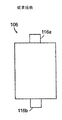
従来の角柱セルは、大きさが対称の(即ち、正と負の延長タブの寸法が同じ)延長タブを有する。図1A、図1Bおよび図1Cは、それぞれ、従来技術の角柱セル102、104、および106を示す。図示するように、延長タブ(セル102に対しては端子112a、112b、セル115に対しては端子114a、114b、セル106に対しては端子116a、116b)の寸法は、それぞれのセルでおおよそ等しい。
Conventional prismatic cells have extension tabs that are symmetrical in size (ie, the dimensions of the positive and negative extension tabs are the same). 1A, 1B, and 1C illustrate prior art
セルの正の延長タブと負の延長タブの上の電流が十分に高い場合、2つの延長タブ中のジュール熱が、端子の外部への熱伝導による熱移動に比べて大きくなる。2つの延長タブは、異なる電気抵抗率と熱伝導率とを有する異なる材料から形成されるため、電流により形成される2つの延長タブでの熱の蓄積は異なる。このため、本質的に異なる熱特性と電気特性を有する材料から形成された対称な延長タブの温度は同じにはならず、1つの延長タブまたは端子が、セルの寿命中により高い温度になる。この温度差は、実際に循環する電流とセルが晒される熱環境に依存するが、セルの寿命および/または性質に関して、大きくなり、セルの性能の制限要因となる。セルが、低抵抗の外部短絡のような酷使される条件に晒された場合に、この問題は特に重要となる。このように、セル温度(および/または最大セル温度)の違いを減らすセルデザインが望まれる。 If the current on the positive and negative extension tabs of the cell is high enough, the Joule heat in the two extension tabs will be larger than the heat transfer due to heat conduction outside the terminals. Since the two extension tabs are formed from different materials having different electrical resistivity and thermal conductivity, the heat accumulation in the two extension tabs formed by the current is different. For this reason, the temperature of symmetrical extension tabs formed from materials having essentially different thermal and electrical properties will not be the same, and one extension tab or terminal will be at a higher temperature during the lifetime of the cell. This temperature difference depends on the actual circulating current and the thermal environment to which the cell is exposed, but increases with respect to the life and / or nature of the cell and becomes a limiting factor in cell performance. This problem is particularly important when the cell is exposed to overworked conditions such as low resistance external shorts. Thus, a cell design that reduces cell temperature (and / or maximum cell temperature) differences is desired.
非対称な電力端子を有する電池セルが提供される。幾つかの具体例では、正極と負極(および対応する電流収集タブ)の大きさは、それぞれの構造の材料の電気抵抗率と熱伝導率に比例して選択される。このデザインは、電気化学セル中の温度差を低減する。電気化学セル中の最大温度(即ち、セルの最も熱い点の温度)も低減される。 A battery cell having an asymmetric power terminal is provided. In some embodiments, the size of the positive and negative electrodes (and corresponding current collection tabs) is selected in proportion to the electrical resistivity and thermal conductivity of the respective structural material. This design reduces the temperature difference in the electrochemical cell. The maximum temperature in the electrochemical cell (ie the temperature at the hottest point of the cell) is also reduced.
幾つかの具体例では、角柱セルが複数の正電極と負電極を含む。正電極に取り付けられた電力端子または延長タブは、正電極の電気特性と化学特性と同程度の第1導電性材料から形成され、負電極に取り付けられた電力端子または延長タブは、負電極の電気特性と化学特性と同程度の第2導電性材料から形成される。リチウムイオン電池では、正の延長タブはアルミニウムからなり、負の延長タブはニッケルまたは銅から形成される。それらの延長タブの組み合わせ(例えば、Al/CuまたはAl/Ni)では、負の延長タブの断面積は、正の延長タブの断面積の約2/3となるように選択される。一の具体例では、正および負の延長タブの厚さは同じであり、負の延長タブの幅が、正の延長タブの幅の約2/3となるように選択される。角柱セルは、例えばリチウムイオンセルである。 In some implementations, the prismatic cell includes a plurality of positive and negative electrodes. The power terminal or extension tab attached to the positive electrode is formed from a first conductive material comparable to the electrical and chemical properties of the positive electrode, and the power terminal or extension tab attached to the negative electrode is It is formed from a second conductive material having the same level of electrical and chemical properties. In lithium ion batteries, the positive extension tab is made of aluminum and the negative extension tab is made of nickel or copper. For those extension tab combinations (eg, Al / Cu or Al / Ni), the cross-sectional area of the negative extension tab is selected to be about 2/3 of the cross-sectional area of the positive extension tab. In one embodiment, the thickness of the positive and negative extension tabs is the same and the width of the negative extension tab is selected to be about 2/3 of the width of the positive extension tab. The prismatic cell is, for example, a lithium ion cell.
本発明の例示的な形態では、電気化学セルは、複数の正および負の電極シートを有するように提供される。電極シートは、それぞれ、電流収集タブを有する。正の端子または延長タブは、正の電極シートの電流収集タブから延び、負の端子または延長タブは、負の電極シートの電流収集タブから延びる。正の延長タブの断面積は、負の延長タブの断面積とは異なる。電極シートは、シートの表面上の活性材料を含み、一方、電流収集タブを形成する電極シートの部分は、活性材料には覆われない。 In an exemplary form of the invention, an electrochemical cell is provided having a plurality of positive and negative electrode sheets. Each electrode sheet has a current collection tab. The positive terminal or extension tab extends from the current collection tab of the positive electrode sheet, and the negative terminal or extension tab extends from the current collection tab of the negative electrode sheet. The cross-sectional area of the positive extension tab is different from the cross-sectional area of the negative extension tab. The electrode sheet includes the active material on the surface of the sheet, while the portion of the electrode sheet that forms the current collection tab is not covered by the active material.
本発明の他の例示的な形態では、電流収集タブを有する複数の正電極シートと、電流収集タブを有する複数の負電極シートとを含むリチウム電池が提供される。電池の電解質は、正および負の電極シートにイオン接合する。正の端子または延長タブは、正の電極シートの電流収集タブから延び、負の端子または延長タブは、負の電極シートの電流収集タブから延びる。ポーチは、正および負の電極シートを囲む。正および負の電極シートの周囲でポーチはシールされ、正の延長タブと負の延長タブはポーチの中から外に引き出される。正の延長タブの断面積は、負極の断面積と異なる。 In another exemplary form of the invention, a lithium battery is provided that includes a plurality of positive electrode sheets having current collection tabs and a plurality of negative electrode sheets having current collection tabs. The battery electrolyte is ion bonded to the positive and negative electrode sheets. The positive terminal or extension tab extends from the current collection tab of the positive electrode sheet, and the negative terminal or extension tab extends from the current collection tab of the negative electrode sheet. The pouch surrounds the positive and negative electrode sheets. The pouch is sealed around the positive and negative electrode sheets, and the positive and negative extension tabs are pulled out of the pouch. The cross-sectional area of the positive extension tab is different from the cross-sectional area of the negative electrode.
本発明の更なる例示的な形態では、電気化学セルの作製方法が提供される。この方法は、電流収集タブを有する複数の正電極シートを提供する工程と、電流収集タブを有する複数の負電極シートを提供する工程とを含む。この方法は、更に、正の電極シートの電流収集タブから正の端子または延長タブを延ばす工程と、負の電極シートの電流収集タブから負の端子または延長タブを延ばす工程とを含む。例えば電気抵抗率や熱伝導率のような延長タブに使用される材料特性に基づいて、正の延長タブの断面積は、負の延長タブの断面積とは異なるように選択される。 In a further exemplary form of the invention, a method for making an electrochemical cell is provided. The method includes providing a plurality of positive electrode sheets having current collection tabs and providing a plurality of negative electrode sheets having current collection tabs. The method further includes extending a positive terminal or extension tab from the current collection tab of the positive electrode sheet and extending a negative terminal or extension tab from the current collection tab of the negative electrode sheet. Based on the material properties used for the extension tab, such as electrical resistivity and thermal conductivity, the cross-sectional area of the positive extension tab is selected to be different from the cross-sectional area of the negative extension tab.
一の具体例では、正および負の延長タブの寸法は、幅と厚さを含む。正の延長タブの幅は、負の延長タブの幅とは異なる。同様に、正の延長タブの厚さは、負の延長タブの厚さとは異なる。 In one embodiment, the dimensions of the positive and negative extension tabs include width and thickness. The width of the positive extension tab is different from the width of the negative extension tab. Similarly, the thickness of the positive extension tab is different from the thickness of the negative extension tab.
一の具体例では、正の電極シートの電流収集タブは互いに溶接され溶接部分を提供する。負の電極シートの電流収集タブもまた互いに溶接され溶接部分を提供する。正の延長タブは、正の電流収集タブの溶接された部分で溶接され、負の延長タブは、負の電流収集タブの溶接された部分で溶接される。 In one embodiment, the current collecting tabs of the positive electrode sheet are welded together to provide a welded portion. The current collecting tabs of the negative electrode sheet are also welded together to provide a welded portion. The positive extension tab is welded at the welded portion of the positive current collection tab and the negative extension tab is welded at the welded portion of the negative current collection tab.
一の具体例では、シール材料は、正の延長タブと負の延長タブの上に配置され、ポーチとともにシールを形成する。ポーチ材料は、例えば、ポリエチレン、ナイロン、およびアルミニウム箔の少なくとも1つを含む積層を含んでも良い。 In one embodiment, the sealing material is disposed on the positive extension tab and the negative extension tab and forms a seal with the pouch. The pouch material may include a laminate including, for example, at least one of polyethylene, nylon, and aluminum foil.
一の具体例では、正の延長タブが、正の電極シートの電流収集タブの最も外側の1つの上に配置され、負の延長タブが、負の電極シートの電流収集タブの最も外側の1つの上に配置される。 In one embodiment, the positive extension tab is disposed on the outermost one of the current collection tabs of the positive electrode sheet and the negative extension tab is the outermost one of the current collection tabs of the negative electrode sheet. Placed on one.
一の具体例では、正の延長タブはアルミニウムを含み、負の延長タブは銅を含み、正の延長タブは約60mmの厚さで、負の延長タブは約40mmの厚さでも良い。 In one embodiment, the positive extension tab comprises aluminum, the negative extension tab comprises copper, the positive extension tab may be about 60 mm thick, and the negative extension tab may be about 40 mm thick.
一の具体例では、セパレータシートは、正の電極シートと負の電極シートの間に挿入される。セパレータシートは、正の電極シートと負の電極シートの間で折り畳まれた連続したシートでも良い。 In one embodiment, the separator sheet is inserted between the positive electrode sheet and the negative electrode sheet. The separator sheet may be a continuous sheet folded between a positive electrode sheet and a negative electrode sheet.
本発明の形態では、正の延長タブは、予め定められた断面積を有し、負の延長タブは、異なる断面積を有し、使用中に、正の延長タブは第1温度を有し、負の延長タブは第2温度を有し、正の延長タブの温度と負の延長タブの温度との間の最適な温度差を形成する。最適温度差は、負の延長タブの断面積に対する正の延長タブの断面積の比を変化させることにより、これ以上は低減できない。 In a form of the invention, the positive extension tab has a predetermined cross-sectional area, the negative extension tab has a different cross-sectional area, and in use, the positive extension tab has a first temperature. The negative extension tab has a second temperature and forms an optimum temperature difference between the temperature of the positive extension tab and the temperature of the negative extension tab. The optimum temperature difference cannot be reduced any further by changing the ratio of the cross-sectional area of the positive extension tab to the cross-sectional area of the negative extension tab.
本発明は以下の図面を参照しながら説明される。図面は、図示のみを目的として提供され、本発明の全範囲は以下の請求項で定義される The present invention will be described with reference to the following drawings. The drawings are provided for purposes of illustration only and the full scope of the invention is defined in the following claims.
非対称な電力端子を有する電池セルについて説明する。幾つかの具体例は、それぞれの電気特性および温度特性に比例した大きさの端子または延長タブを有するセルを提供する。これは、セルの温度勾配(即ち、セル中の最高温度と最低温度との間の差)と同様に、セルの最も熱い点の温度の低減を可能にする。セルの性能や安全性は、一般に、セル中の最も熱い点の温度により制限されるため、それぞれの電気特性および温度特性に比例した大きさの端子または延長タブを有するセルは、増加した速度、増加したセルの寿命、増加したセルの安全性、および/またはそれらの効果のいくつかの組み合わせでのサイクルが可能となる。 A battery cell having an asymmetric power terminal will be described. Some embodiments provide cells having terminals or extension tabs sized proportional to their respective electrical and temperature characteristics. This allows a reduction in the temperature of the hottest point of the cell as well as the temperature gradient of the cell (ie, the difference between the highest and lowest temperature in the cell). Since cell performance and safety are generally limited by the temperature of the hottest point in the cell, cells with terminals or extension tabs sized proportionally to their respective electrical and temperature characteristics will have increased speed, Cycles with increased cell lifetime, increased cell safety, and / or some combination of these effects are possible.
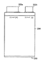
図2Aは、様々な具体例にかかる角柱電池セル200の正面図である。図2Bは、図2Aに示す角柱電池セルの側面図である。セル200は、大きさが非対称な正の電力端子または延長タブ202a、および負の電力端子または延長タブ202bを有する。(電極シートの電流収集タブから延びる)非対称な端子は、比較的薄い電極を用いるセルの化学に実質的に適用できる。非対称な延長タブの熱特性は、比較的速い速度で動作するように設計されたセルに対して有用である。高速で行われる典型的なセルの化学作用は、ニッケル/金属水素化物、またはニッケル/カドミウムである。セル200は、例えば、リチウムイオン電池である。幾つかの具体例では、延長タブ202aは正電極の電流収集タブに取り付けられ、延長タブ202bは負電極の電流収集タブに取り付けられる。正電極の電流収集タブは、アルミニウムから形成され、負電極の電流収集タブは、銅またはニッケルから形成される。
FIG. 2A is a front view of a
電気化学セルの電流コレクタおよび延長タブが形成される材料は、一般に、電解質およびセルの電圧と電気化学的に互換性のあるものに限られる。3〜5Vの開路電位(open circuit potential)で動作する有機溶媒ベースの電解質を用いたリチウムイオンセルの場合、電解質で濡らされる正の電流コレクタ、正のタブ、および正電極電位の他の導電性要素は、正電極電位の電位で、電食に耐えなければならない。リチウムイオンセルの正電極電位で電食に耐性があるように振る舞う材料は、例えばアルミニウム、モリブデン、チタン、および所定のステンレス鋼合金を含む。それらの材料のうち、アルミニウムは、費用比率で最も高い電気伝導率と熱伝導率を有し、正電極電位で使用するための例示的な材料となる。3〜5Vの開路電位で動作する有機溶媒ベースの電解質を用いたリチウムイオンセルの場合、電解質で濡らされる負の電流コレクタ、負のタブ、および負電極電位の他の導電性要素は、負電極電位で、リチウムとの合金化に耐えなければならない。リチウムイオンセルの負電極電位でリチウムとの合金化に耐性があるように振る舞う材料は、例えば銅、ニッケル、および鉄を含む。それらの材料のうち、銅は、最良の電気伝導率と熱伝導率を有し、リチウムイオンセルの負電極電位で使用するための例示的な材料となる。 The materials from which electrochemical cell current collectors and extension tabs are formed are generally limited to those that are electrochemically compatible with electrolyte and cell voltages. In the case of a lithium ion cell using an organic solvent based electrolyte operating at an open circuit potential of 3-5V, the positive current collector wetted by the electrolyte, the positive tab, and other conductivity of the positive electrode potential The element must withstand electrolytic corrosion at a positive electrode potential. Materials that behave to be resistant to electrolytic corrosion at the positive electrode potential of a lithium ion cell include, for example, aluminum, molybdenum, titanium, and certain stainless steel alloys. Of these materials, aluminum has the highest electrical and thermal conductivity in terms of cost and is an exemplary material for use at the positive electrode potential. In the case of a lithium ion cell using an organic solvent-based electrolyte operating at an open circuit potential of 3-5 V, the negative current collector, negative tab, and other conductive elements that are wetted by the electrolyte are the negative electrode Must withstand alloying with lithium at the potential. Materials that behave to be resistant to alloying with lithium at the negative electrode potential of the lithium ion cell include, for example, copper, nickel, and iron. Of these materials, copper has the best electrical and thermal conductivity and is an exemplary material for use at the negative electrode potential of lithium ion cells.
上述のように、延長タブ202a、202bは、同じ大きさではない。幾つかの具体例では、負の延長タブ202bの幅は、正の延長タブ202aの幅の約2/3となるように選択され、延長タブの厚さは同じである。この場合、負の延長タブ202bの断面積は、正の延長タブ202aの断面積の約2/3である。例えば、延長タブ202aがアルミニウムから形成され、延長タブ202bが銅またはニッケルから形成された場合に、この非対称の端子のデザインは、セルが使用された場合の、温度勾配と共に、2つの電力延長タブ202a、202bのための温度差を減らす。その時の所定の点のうちのセルの最高温度(即ち、セルの最も熱い点の温度)も低減される。
As described above, the
延長タブ202a、202bがアルミニウム、銅、またはニッケル以外の材料から形成された場合、延長タブの異なる寸法は、セルの最高温度と温度勾配を低減するように選択される。延長タブの断面積は、延長タブの温度の決定要因であり、セルの最高温度と温度勾配に影響する。2つの延長タブの厚さが等しくなるように選択された場合、延長タブの幅は、最適効果を達成するように調整できる。しかしながら、2つの端子の厚さは、同様になるように選択される必要は無い。
If the
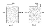
図3は、幾つかの具体例にかかる角柱電池セルの、カソードとアノードのシート302a、302bと、取り付けられた電流収集タブ304a、304bを示す概略図である。電極シートの寸法は、所望の熱特性および電気特性を与え、セルの体積の要求(例えば、利用できる空間)と整合するようないずれかの範囲である。例として、カソードシートは約143mmの幅、198mmの長さであり、アノードシートは、約145mmの幅、200mmの長さである。描写したように電流収集タブ304bは、電流収集タブ304aの幅の、約2/3の幅を有する。例示として、電流収集タブ304aの幅は、約56.5mmとなるように選択され、電流収集タブ304bの幅は約36.0mmとなるように選択される。電流収集タブは、製造プロセス中に切断されて、適当な高さにしても良い。
FIG. 3 is a schematic diagram showing cathode and
電極シート302aは、この分野で知られている第1活性材料306aを含む。電極シート302aの電流収集タブ304aは、活性材料306aにより覆われていない電極シート302aの延長した部分である。同様に、電極シート302bは、活性材料306bを含む。負電極シート302bの電流収集タブ304bは、材料306bにより覆われていない負電極シート302bの延長した部分である。
The
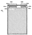
図4は、角柱電池セルに組み立てられる前の、セパレータシート404の一部に載置された一連のカソードとアノードのシート(例えば、302a、302b)を示す概略図である。電極シート(例えば、302a、302b)を備えたセパレータシート404は、水平方向に、例えばアコーディオンのひだのように折り畳まれ、電極シートは一枚ずつ積層され、セパレータシート404で分離される。折り畳みプロセスは、スタック巻き(stack-winding)と呼ばれる。電極302a、302bの相対位置は適当な積層とセパレータシートの間の電極のアラインメントのために選択される。セパレータシートの寸法は、電極を分離するのに必要で、セルの体積の要求(例えば、得られる空間)と整合するようないずれかの範囲である。例えば、電極が143〜145mmの幅であると仮定すると、セパレータシートは、約206mmの幅と0.025mmの厚さになりセパレータシート上に配置された場合の電極間の距離は約145mmとなる。
FIG. 4 is a schematic diagram illustrating a series of cathode and anode sheets (eg, 302a, 302b) mounted on a portion of the
アノードシート(例えば、シート302b)の上の電流収集タブ(例えば、シート304b)の相対位置は、スタック巻きの後に、タブが互いに垂直方向に整列するように形成される。同様に、カソードシート(例えば、シート302a)の上の電流収集タブ(例えば、シート304a)の位置は、スタック巻きの後に、タブが互いに垂直方向に整列するように選択される。幾つかの具体例では、角柱セルの中には、約20から30のアノードシートと、20から30のカソードシートがある。スタック巻の後に、電池セルの内部構成要素(例えば、電極およびセパレータシト)は密封封止される。一の具体例では、内部構成要素は、ポーチ材料からなる囲いの中にシールされる。典型的なセルポーチ材料は、ポリエチレン、ナイロン、およびアルミニウム箔の積層を含む。しかしながら、他の好適な囲いをセルの内部構成要素のシールに用いても良い。
The relative position of current collection tabs (eg,
延長タブは、電流収集タブに溶接またはそうでなければ貼り付けられる。延長タブは、以下でより詳しく検討するように、シールのための材料のストリップを含む。図5は、正および負の電極シート302a、302bの電流収集タブ304a、304bに取り付けられた、延長タブ308a、308bの、それぞれの正面図および側面図を示す。延長タブ308a、308bの寸法は、所望の温度特性と電気特性を提供でき、セルの体積の要求(例えば、得られる空間)と整合するようないずれかの範囲を有する。例では、延長タブ308a、308bの厚さは、約0.4mmである。封止ストリップ504a、504bは、延長タブ308a、308bのそれぞれを横切って配置される。ストリップ504a、504bは、電池セルの内部構成要素を封止するために使用され、これについては図7に関連して説明する。
The extension tab is welded or otherwise affixed to the current collection tab. The extension tab includes a strip of material for sealing, as will be discussed in more detail below. FIG. 5 shows respective front and side views of
一旦、電流収集タブ304a、304bが積層されれば、一般にはタブアセンブリの厚さ方向に溶接することで、それらは延長タブ304a、304bを用いて互いに接続される。図6は、角柱電池セルのタブアセンブリの寸法と溶接位置を示す概略図である。図6は、スタック溶接後の、電流収集タブ304a、304bと延長タブ308a、308bの位置を示す。延長タブ308a、308bは、先に示したように取り付けられたストリップ504a、504bを有する。電流収集タブ304a、304bと延長タブ308a、308bは、ストリップ504a、504bの下にそれぞれ溶接セクション604a、604bを有する。溶接セクション604a、604bでは、正の電流収集タブ(例えば、タブ304a)と負の電流収集タブ(例えば、タブ304b)が、例えば超音波溶接、抵抗溶接、レーザー溶接、または他の好適な溶接技術を用いて、互いに溶接される。延長タブ308a、308bは、溶接されてそれぞれ電流収集タブ304a、304bと一体にされる。図6に示したように、延長タブ308a、308bの底部310a、310bは、一体となった電流収集タブ304a、304bと重なり、例えば、1つの延長タブ308aが、一体となった電流収集タブ304aから延びる。同様に、1つの延長タブ308bが、一体となった電流収集タブ304bから延びる。一体となった電流収集タブ304a、304bの断面積は互いに異なり、本発明にかかる好適な比を提供する。一の具体例では、電流収集タブは、延長タブが電流収集タブに溶接されるのと同時に、互いに溶接されても良い。これは、例えば、超音波溶接方法が用いられる場合であり、超音波溶接からの刺激が、形成される溶接の近傍で他の溶接にダメージを与えるためである。他の具体例では、電流収集タブと延長タブが、同時に互いに接続される必要は無く、別々のプロセスで取り付けることができる。
Once the
一の具体例では、延長タブは薄く、平坦なタブであり、正の延長タブ308aの長さと幅は、それぞれ、正の延長タブ308aの厚さの少なくとも10倍である。負の延長タブ308bの長さと幅は、それぞれ、負の延長タブ308bの厚さの少なくとも10倍である。延長タブ308a、308bの長さの寸法は、図6に垂直方向に拡がって示され、幅の寸法は水平方向に拡がって示される。延長タブの厚さの寸法は、図6のページに向かう方向に拡がり、図2Bの具体例に示される。他の具体例では、正の延長タブの長さと幅は、正の延長タブの厚さの少なくとも50倍であり、負の延長タブの長さと幅は、負の延長タブの厚さの少なくとも50倍である。他の具体例では、正の延長タブの長さと幅は、正の延長タブの厚さの少なくとも100倍であり、負の延長タブの長さと幅は、負の延長タブの厚さの少なくとも100倍である。図7に示すように、正の電極シートと負の電極シートの周囲でポーチがシールされ、正の延長タブ308aと負の延長タブ308bがポーチの外側に延びても良い。
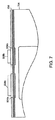
In one embodiment, the extension tab is a thin, flat tab, and the length and width of the
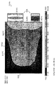
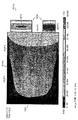
特に、図7は、幾つかの具体例にかかる角柱電池セルの上部シール706を示す概略図である。セルの囲いまたはポーチ704の一部を示す。セルの囲い704は、セルアセンブリの内部構成要素を囲むために用いられる。幾つかの具体例では、囲い704は、積層された電極の表面と裏面とに配置されたポーチ材料の2つのシートを含み、これらは、囲いの端部で互いに継ぎ合わされ、積層電極を密封シールする。ストリップ504a、504bは、囲い704のポーチ材料に合うような材料から形成され、セル囲いシートの上端部が互いに継ぎ合わされる場合、上端部はストリップ504a、504b(およびそれゆえにタブアセンブリと)に固く取り付けられ、この部分ではタブアセンブリによりそれらが分離される。この方法では、上部シール706が、それぞれが延長タブ308a、308bに取り付けられたストリップ504a、504bを横切って形成される。例では、シールの幅は約5mmである。セパレータシート404は、電極プレート302a、302bの間に示される。
In particular, FIG. 7 is a schematic diagram illustrating a prismatic battery cell
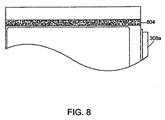
図8は、囲いシートの横端部を互いに継ぎ合わせることにより形成された角柱電池セルのサイドシール804を示す概略図である。例では、サイドシール804の幅は、約10mmである。なお、図7〜図8は、セル囲いの1つのタイプについて示すが、他の好適なセル囲いのタイプを、セルアセンブリの内部構成要素を密封シールするのに用いても良い。図9は、幾つかの具体例にかかる、完成した角柱電池セル200の1つの例の、様々な構成要素を示し、電流収集タブ304a、304b、延長タブ308a、308b、溶接セクション604a、604b、およびストリップ504a、504bを含む。
FIG. 8 is a schematic view showing a prismatic battery
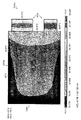
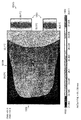
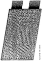
延長タブ308a、308bの間の、異なる断面積の比について、本発明から得られる利点を示すために、シミュレーションが行われた。図10〜図16は、この目的のためのシミュレーション実施の結果を示す概略図である。図10〜図16は、様々な角柱電池セルデザインの温度分布を示す。概略図は、214×153×7.3mmのセルボディを有する角柱セルの3D過渡温度解析で得られたデータに基づく。熱分析は、電池セルのコンピュータモデルを用いたシミュレーションに基づく。コンピュータモデルは、図17に示されるような有限要素モデルであり、セルは、分析のために、小さな4面体の熱固体要素に分けられる。シミュレーションのために、所定の熱発生特性および熱伝導特性が、電池セルの様々な部分のために選択される。例えば、セルボディは、直交異方性の熱伝導特性を有する熱発生源としてモデル化され、電力端子(または延長タブ)は、等方性の熱伝導特性を有する熱発生源としてモデル化される。特に、セルボディは、密度が2.7e+006g/m^3、比熱が1J/gK、熱伝導率がX、Y方向に40W/mK、Z方向に0.6W/mKと仮定される(g=グラム、m=メータ、J=ジュール、K=ケルビン、およびW=ワット)。比熱は、エネルギの量であり、単位体積あたりの材料の温度を上げるのに用いられる。正のタブは、密度が2.7e+006g/m^3、比熱が0.904J/gK、熱伝導率がX、Y、Z方向に230W/mKと仮定される。負のタブは、密度が8.96e+006g/m^3、比熱が0.385J/gK、熱伝導率がX、Y、Z方向に385W/mKと仮定される。セルからの熱移動は、広くて平坦なセルの空気に対する表面で周囲の温度への対流により、および35℃の一定温度に接続することによりタブの端部を通って起きるものと仮定される。周囲の温度は35℃と仮定され、対流膜係数(convection film coefficient)は10W/m^2Kと仮定される。
Simulations were performed to show the benefits obtained from the present invention for different cross-sectional area ratios between the
図10〜図16の概略図は、モデル化された異なるデザインのセルの正面図を示し、セルボディ(例えば、図10のセルボディ1004)や延長タブ(例えば、図10のターミナル1006)を含む。延長タブの寸法は、それぞれの概略図の底部に示される(例えば、図10では位置1008)。60秒後の、電池セルを横切る電池セルの温度が、温度スケールを用いて表される(例えば、図10のスケール1002)。例では、図10において、領域1010aは温度スケール1002の下端部に対応し、それゆえに約30.9℃の温度を有し、領域1010bは温度スケール1003の上端部に対応し、それゆえに約40.6℃の温度を有する。セルの最高温度と最低温度は、示されたセルの上部左に示される(例えば、図10の位置1012)。
The schematic diagrams of FIGS. 10-16 show front views of differently modeled cells that are modeled, including cell bodies (eg,
図10は、電力端子また延長タブが同じ寸法(50mm)の場合、2つの端子の温度が異なることを示す。アルミニウムの延長タブが約50mmの幅で、銅のタブが約50mmの幅の場合、2つの端子の温度は同一にはならない。この結果、温度勾配が発生する。 FIG. 10 shows that when the power terminals or extension tabs have the same dimensions (50 mm), the temperatures of the two terminals are different. If the aluminum extension tab is about 50 mm wide and the copper tab is about 50 mm wide, the temperature of the two terminals will not be the same. As a result, a temperature gradient is generated.
図11は、アルミニウムタブが約60mmの幅で、銅のタブが約40mmの幅の場合、2つの端子間の温度勾配が低減されることを示す。60秒後において、最低温度は約31.9℃であり、最高温度は約38.5℃である。この結果、温度勾配はより小さくなり、図11のセルの最も熱い点の温度は、図10のセルの最も熱い点の温度より低くなる。 FIG. 11 shows that if the aluminum tab is about 60 mm wide and the copper tab is about 40 mm wide, the temperature gradient between the two terminals is reduced. After 60 seconds, the minimum temperature is about 31.9 ° C and the maximum temperature is about 38.5 ° C. As a result, the temperature gradient is smaller and the temperature of the hottest point of the cell of FIG. 11 is lower than the temperature of the hottest point of the cell of FIG.
図12は、アルミニウムタブが約65mmの幅で、銅のタブが約35mmの幅の場合、2つの端子間の温度勾配が変わることを示す。60秒後において、最低温度は約31.9℃であり、最高温度は約39.4℃であり、これにより、延長タブの間の異なる断面積の比により、温度が変化することが示される。図13は、アルミニウムタブが約63mmの幅で、銅のタブが約37mmの幅の場合を示す。60秒後において、最低温度は約31.9℃であり、最高温度は約38.8℃である。図14は、アルミニウムタブが約62mmの幅で、銅のタブが約38mmの幅の場合を示し、最高温度は、図12や図13の場合に比較して低くなることを示す。60秒後において、最低温度は約32℃であり、最高温度は得約38.6℃である。 FIG. 12 shows that the temperature gradient between the two terminals changes when the aluminum tab is about 65 mm wide and the copper tab is about 35 mm wide. After 60 seconds, the minimum temperature is about 31.9 ° C. and the maximum temperature is about 39.4 ° C., which indicates that the temperature varies with the ratio of the different cross-sectional areas between the extension tabs. . FIG. 13 shows the case where the aluminum tab is about 63 mm wide and the copper tab is about 37 mm wide. After 60 seconds, the minimum temperature is about 31.9 ° C and the maximum temperature is about 38.8 ° C. FIG. 14 shows the case where the aluminum tab is about 62 mm wide and the copper tab is about 38 mm wide, and the maximum temperature is lower than in the case of FIGS. 12 and 13. After 60 seconds, the minimum temperature is about 32 ° C and the maximum temperature is about 38.6 ° C.
図15および図16は、アルミニウムタブが約61mmの幅で、銅のタブが約39mmの幅の場合であり、60秒後において2つの端子の温度は同一である。この結果、温度勾配はより小さくなる。図15および図16に結果が示された分析は、図16に対して選択された異なるASIを除いて、同一である。セルのボディの体積熱発生は、ASIに直接比例する。図15と図16の重要性は、本発明の例示的な具体例が、熱生成の1つの速度のみであるのとは対照的に、熱生成の速度の範囲において有用性を有することを示すことである。図15は、最高温度38.111を示す。図16は最高温度42.994を示す(「SMX」は、プロット中に示される最高温度を示す)。 FIGS. 15 and 16 show the case where the aluminum tab has a width of about 61 mm and the copper tab has a width of about 39 mm, and the temperature of the two terminals is the same after 60 seconds. As a result, the temperature gradient becomes smaller. The analyzes whose results are shown in FIGS. 15 and 16 are identical except for the different ASIs selected for FIG. The volumetric heat generation of the cell body is directly proportional to the ASI. The importance of FIGS. 15 and 16 shows that the exemplary embodiment of the present invention has utility in a range of heat generation rates, as opposed to only one rate of heat generation. That is. FIG. 15 shows the maximum temperature 38.111. FIG. 16 shows a maximum temperature of 42.994 (“SMX” indicates the maximum temperature shown in the plot).
このように、分析は、図10〜図17と関連して示され、セルの最も熱い点の温度の最小化や低減と共に、好適な温度勾配を提供する本発明の有益な形態を示す。 Thus, the analysis is shown in connection with FIGS. 10-17 and illustrates a beneficial form of the invention that provides a suitable temperature gradient with minimization or reduction of the hottest point temperature of the cell.
図18は、時間における角柱電池セルの様々な点における温度変化を示す。電池セルは、幅が61mmの正のアルミニウムの延長タブと、幅が39mmの負の銅の延長タブとを有する。図は、上述の熱分析から得られたデータに基づく。線「T中心(Tcenter)」は、セルボディの中心における温度変化を示す。線「T負タブ(Tnegtab)」と「T正タブ(Tpostab)」は、セルボディとの交差点における、負の延長タブと正の延長タブとの中央における温度変化をそれぞれ示す。示されるように、正の延長タブにおける温度は、負の延長タブにおける温度と比較的近くなる。 FIG. 18 shows temperature changes at various points of the prismatic battery cell over time. The battery cell has a positive aluminum extension tab having a width of 61 mm and a negative copper extension tab having a width of 39 mm. The figure is based on data obtained from the thermal analysis described above. The line “Tcenter” indicates the temperature change at the center of the cell body. The lines “T negative tab (Tnegtab)” and “T positive tab (Tpostab)” indicate the temperature change at the center of the negative extension tab and the positive extension tab, respectively, at the intersection with the cell body. As shown, the temperature at the positive extension tab is relatively close to the temperature at the negative extension tab.
図19は、角柱電池セルの温度と電圧の、時間に対する変化を示す図である。セルのボディは、7.5×150×200mmの寸法を有する。正の延長タブは幅が56.5mmであり、負の延長タブは幅が36mmである。図に示されるように、正の延長タブの温度は、負の延長タブの温度と比較的近い。 FIG. 19 is a diagram illustrating changes in temperature and voltage of the prismatic battery cell with respect to time. The body of the cell has dimensions of 7.5 × 150 × 200 mm. The positive extension tab is 56.5 mm wide and the negative extension tab is 36 mm wide. As shown in the figure, the temperature of the positive extension tab is relatively close to the temperature of the negative extension tab.
上述の記載は、角柱セルデザインに集中したが、本発明の具体例は、円筒形セルのような他の電池セルにも適用することができる。例えば、円筒形セルでは、正および負の端子のための電流収集タブまたは延長タブの寸法は、それらのそれぞれの構成材料の電気抵抗率や温度伝導率に比例して形成され、これにより温度勾配および/または最高温度は低減される。電池の寿命と安全性の観点から、これは、円筒形セルの性能に有益である。また、本発明の具体例は、比較的薄い電極を用いる電気化学的セルにも適用でき、これらは、比較的高速で動作するように設計される。そのようなセルの例は、ニッケル/金属水素化物セルやニッケル/カドミウムセルを含む。様々な具体例が、例示としてここに示され、記載されたが、当業者は本発明の精神や範囲から離れることなく変形を行うことが理解されるであろう。 Although the above description has focused on prismatic cell designs, embodiments of the present invention can be applied to other battery cells such as cylindrical cells. For example, in a cylindrical cell, the dimensions of the current collection tabs or extension tabs for the positive and negative terminals are formed in proportion to the electrical resistivity and temperature conductivity of their respective constituent materials, thereby creating a temperature gradient And / or the maximum temperature is reduced. From the point of view of battery life and safety, this is beneficial for the performance of cylindrical cells. Embodiments of the present invention can also be applied to electrochemical cells using relatively thin electrodes, which are designed to operate at relatively high speeds. Examples of such cells include nickel / metal hydride cells and nickel / cadmium cells. While various embodiments have been shown and described herein by way of example, those skilled in the art will recognize that modifications can be made without departing from the spirit and scope of the invention.
Claims (44)
電流収集タブを有する複数の正の電極シートと、
電流収集タブを有する複数の負の電極シートであって、正と負の電極シートはセル中に重ねられる負の電極シートと、
正の電極シートの電流収集タブから延びた正の延長タブと、
負の電極シートの電流収集タブから延びた負の延長タブと、を含み、
正の延長タブの断面積は、負の延長タブの断面積とは異なる電気化学セル。 An electrochemical cell,
A plurality of positive electrode sheets having current collection tabs;
A plurality of negative electrode sheets having current collection tabs, the positive and negative electrode sheets being overlaid in the cell;
A positive extension tab extending from the current collection tab of the positive electrode sheet;
A negative extension tab extending from the current collection tab of the negative electrode sheet, and
The electrochemical cell in which the cross-sectional area of the positive extension tab is different from the cross-sectional area of the negative extension tab.
負の電極シートは第2の活性材料を含み、負の電極シートの電流収集タブは、第2の活性材料で覆われていない負の電極シートの延びた部分である請求項1に記載の電気化学セル。 The positive electrode sheet includes a first active material, and the current collection tab of the positive electrode sheet is an extended portion of the positive electrode sheet that is not covered with the first active material;
2. The electricity of claim 1, wherein the negative electrode sheet includes a second active material, and the current collection tab of the negative electrode sheet is an extended portion of the negative electrode sheet that is not covered by the second active material. Chemical cell.
最適な温度差は、正の延長タブと負の延長タブの断面積の比を変えることによっては、これ以上は低減されない請求項1に記載の電気化学セル。 The positive extension tab has a predetermined cross-sectional area, the negative extension tab has a different predetermined cross-sectional area, and in use, the positive extension tab has a first temperature and the negative extension tab has a first Having an optimum temperature difference between the temperature of the positive extension tab and the temperature of the negative extension tab,
The electrochemical cell of claim 1, wherein the optimum temperature difference is not further reduced by changing the ratio of the cross-sectional area of the positive extension tab and the negative extension tab.
電流収集タブを有する複数の正の電極シートと、
電流収集タブを有する複数の負の電極シートと、
正の電極シートと負の電極シートにイオン接触する電解質と、
正の電極シートの電流収集タブから延びた正の延長タブと、
負の電極シートの電流収集タブから延びた負の延長タブと、
正の電極シートと負の電極シートとを囲むポーチであって、正の延長タブと負の延長タブが、ポーチの内側から外側に延びるように、正の電極シートと負の電極シートの周囲をシールするポーチと、を含み、
正の延長タブの断面積は、負の延長タブの断面積と異なるリチウム電池。 A lithium battery,
A plurality of positive electrode sheets having current collection tabs;
A plurality of negative electrode sheets having current collecting tabs;
An electrolyte in ionic contact with the positive electrode sheet and the negative electrode sheet;
A positive extension tab extending from the current collection tab of the positive electrode sheet;
A negative extension tab extending from the current collection tab of the negative electrode sheet;
A pouch that surrounds the positive electrode sheet and the negative electrode sheet. A pouch for sealing,
The lithium battery has a cross-sectional area different from that of the negative extension tab.
負の電極シートは第2の活性材料を含み、負の電極シートの電流収集タブは、第2の活性材料に覆われない負の電極シートの延長された部分である請求項20に記載のリチウム電池。 The positive electrode sheet includes a first active material, and the current collection tab of the positive electrode sheet is an extended portion of the positive electrode sheet that is not covered by the first active material;
21. The lithium of claim 20, wherein the negative electrode sheet comprises a second active material, and the current collection tab of the negative electrode sheet is an extended portion of the negative electrode sheet that is not covered by the second active material. battery.
電流収集タブを備えた複数の正の電極シートを準備する工程と、
電流収集タブを備えた複数の負の電極シートを準備する工程と、
正の電極シートの電流収集タブから正の延長タブを延ばす工程と、
負の電極シートの電流収集タブから負の延長タブを延ばす工程と、
正の延長タブの断面積を、負の延長タブの断面積と異なるように選択する工程と、を含む方法。 A method of making an electrochemical cell, comprising:
Providing a plurality of positive electrode sheets with current collection tabs;
Providing a plurality of negative electrode sheets with current collection tabs;
Extending a positive extension tab from the current collection tab of the positive electrode sheet;
Extending a negative extension tab from the current collection tab of the negative electrode sheet;
Selecting the cross-sectional area of the positive extension tab to be different from the cross-sectional area of the negative extension tab.
負の電極シートの電流収集タブが、負の電極シートの延びた部分となり、第2の活性材料に被覆されないように、負の電極シートの一部を第2の活性材料で被覆する工程と、を含む請求項29に記載の方法。 Further, coating a portion of the positive electrode sheet with the first active material such that the current collection tab of the positive electrode sheet becomes an extended portion of the positive electrode sheet and is not coated with the first active material. When,
Coating a portion of the negative electrode sheet with the second active material such that the current collection tab of the negative electrode sheet becomes an extended portion of the negative electrode sheet and is not coated with the second active material; 30. The method of claim 29, comprising:
最適な温度差は、正の延長タブと負の延長タブの断面積の比を変えることによっては、これ以上は低減されない請求項29に記載の方法。 In use, the positive extension tab has a first temperature, the negative extension tab has a second temperature, and an optimum temperature difference between the temperature of the positive extension tab and the temperature of the negative extension tab. Forming a positive extension tab to have a predetermined cross-sectional area to form a negative extension tab to have a different predetermined cross-sectional area,
30. The method of claim 29, wherein the optimum temperature difference is not further reduced by changing the ratio of the cross sectional area of the positive extension tab and the negative extension tab.
電流収集タブを有する複数の正の電極シートと、
電流収集タブを有する複数の負の電極シートであって、正と負の電極シートはセル中に重ねられる負の電極シートと、
正の電極シートの電流収集タブから延びた正の延長タブと、
負の電極シートの電流収集タブから延びた負の延長タブと、を含み、
正の延長タブおよび負の延長タブは、それぞれが所定の長さ、幅、および厚さを有し、
正の延長タブの断面積は、負の延長タブの断面積とは異なり、
正の延長タブの長さと幅は、それぞれ、正の延長タブの厚さの少なくとも10倍であり、負の延長タブの長さと幅は、それぞれ、負の延長タブの厚さの少なくとも10倍である電気化学セル。 An electrochemical cell,
A plurality of positive electrode sheets having current collection tabs;
A plurality of negative electrode sheets having current collection tabs, the positive and negative electrode sheets being overlaid in the cell;
A positive extension tab extending from the current collection tab of the positive electrode sheet;
A negative extension tab extending from the current collection tab of the negative electrode sheet, and
The positive extension tab and the negative extension tab each have a predetermined length, width, and thickness;
The cross-sectional area of the positive extension tab is different from the cross-sectional area of the negative extension tab,
The length and width of the positive extension tab are each at least 10 times the thickness of the positive extension tab, and the length and width of the negative extension tab are each at least 10 times the thickness of the negative extension tab. An electrochemical cell.
Applications Claiming Priority (2)
| Application Number | Priority Date | Filing Date | Title |
|---|---|---|---|
| US99160207P | 2007-11-30 | 2007-11-30 | |
| PCT/US2008/084759 WO2009073492A2 (en) | 2007-11-30 | 2008-11-25 | Battery cell design with asymmetrical terminals |
Publications (2)
| Publication Number | Publication Date |
|---|---|
| JP2011505671A true JP2011505671A (en) | 2011-02-24 |
| JP2011505671A5 JP2011505671A5 (en) | 2012-01-12 |
Family
ID=40718447
Family Applications (1)
| Application Number | Title | Priority Date | Filing Date |
|---|---|---|---|
| JP2010536145A Pending JP2011505671A (en) | 2007-11-30 | 2008-11-25 | Battery cell design with asymmetric terminals |
Country Status (8)
| Country | Link |
|---|---|
| US (1) | US8501345B2 (en) |
| EP (3) | EP3242347B1 (en) |
| JP (1) | JP2011505671A (en) |
| KR (1) | KR101572014B1 (en) |
| CN (1) | CN101911342B (en) |
| PL (1) | PL3242347T3 (en) |
| TW (1) | TWI459621B (en) |
| WO (1) | WO2009073492A2 (en) |
Cited By (8)
| Publication number | Priority date | Publication date | Assignee | Title |
|---|---|---|---|---|
| JP2013161559A (en) * | 2012-02-02 | 2013-08-19 | Nissan Motor Co Ltd | Electric device module |
| WO2013146735A1 (en) * | 2012-03-27 | 2013-10-03 | 株式会社 豊田自動織機 | Power storage device |
| JP2013254705A (en) * | 2012-06-08 | 2013-12-19 | Toyota Industries Corp | Power storage device and method for manufacturing electrode assembly |
| JP2017027819A (en) * | 2015-07-23 | 2017-02-02 | 日立オートモティブシステムズ株式会社 | Secondary battery |
| JP2018142478A (en) * | 2017-02-28 | 2018-09-13 | オートモーティブエナジーサプライ株式会社 | Secondary battery |
| JP2018174032A (en) * | 2017-03-31 | 2018-11-08 | Tdk株式会社 | Nonaqueous electrolyte secondary battery |
| JP2020095910A (en) * | 2018-12-14 | 2020-06-18 | 積水化学工業株式会社 | Stacked battery |
| JP2020518095A (en) * | 2017-04-20 | 2020-06-18 | エー123 システムズ エルエルシーA123 Systems LLC | Battery tab structure |
Families Citing this family (25)
| Publication number | Priority date | Publication date | Assignee | Title |
|---|---|---|---|---|
| DE202010018323U1 (en) * | 2010-04-26 | 2016-01-27 | Continental Automotive Gmbh | Energy storage cell |
| KR20120009577A (en) * | 2010-07-19 | 2012-02-02 | 주식회사 엘지화학 | Secondary electric cell with differential lead structure |
| WO2012051402A1 (en) * | 2010-10-15 | 2012-04-19 | A123 Systems, Inc. | Integral battery tab |
| US20120177982A1 (en) * | 2011-01-07 | 2012-07-12 | Samsung Sdi Co., Ltd. | Secondary battery |
| US9153844B2 (en) | 2011-01-31 | 2015-10-06 | General Electric Company | System and methods of using a sodium metal halide cell |
| KR101305250B1 (en) * | 2011-07-25 | 2013-09-06 | 주식회사 엘지화학 | Battery Module of Improved Reliability and Battery Pack Employed with the Same |
| DE102011110007A1 (en) | 2011-08-11 | 2013-02-14 | Li-Tec Battery Gmbh | Electrochemical energy storage e.g. galvanic cell, for use in motor car, has electrode assembly including sequence of electrodes, where arrester tabs of current collectors protruded from electrode assembly are combined between two of arms |
| WO2013020677A2 (en) | 2011-08-11 | 2013-02-14 | Li-Tec Battery Gmbh | Electrochemical energy store and process for the production thereof |
| CN104137303B (en) | 2012-04-16 | 2017-08-08 | 株式会社Lg 化学 | Include positive pole and the electrode assemblie of negative pole and the secondary cell for including the electrode assemblie with different weld part shapes |
| WO2013180482A1 (en) | 2012-05-30 | 2013-12-05 | 주식회사 엘지화학 | Electrode assembly having superior electrode tab-joining properties, battery cell and device comprising same, and method for manufacturing electrode assembly |
| DE102012215748A1 (en) | 2012-09-05 | 2014-03-06 | Robert Bosch Gmbh | Electric energy storage cell and method for producing an electrical energy storage cell |
| US20140120383A1 (en) * | 2012-10-25 | 2014-05-01 | John Bradford Janik | Apparatus and method for high power density power discharge from a battery pack |
| US9123949B2 (en) | 2013-09-17 | 2015-09-01 | Lg Chem, Ltd. | Battery module and battery cell |
| US9123950B2 (en) | 2013-09-26 | 2015-09-01 | Lg Chem, Ltd. | Battery module and battery cell |
| JP6362065B2 (en) * | 2013-12-11 | 2018-07-25 | 三星エスディアイ株式会社Samsung SDI Co., Ltd. | Battery built-in belt |
| US9748532B2 (en) * | 2013-12-11 | 2017-08-29 | Samsung Sdi Co., Ltd. | Belt with built-in batteries |
| US9172122B2 (en) | 2014-02-25 | 2015-10-27 | Lg Chem, Ltd. | Battery module |
| KR102504791B1 (en) * | 2015-10-23 | 2023-02-27 | 삼성에스디아이 주식회사 | Rechargeable battery having cover |
| JP6645999B2 (en) * | 2017-03-21 | 2020-02-14 | 株式会社東芝 | Rechargeable battery, battery pack, and vehicle |
| JP6737218B2 (en) * | 2017-03-31 | 2020-08-05 | Tdk株式会社 | Non-aqueous electrolyte secondary battery |
| US10431816B2 (en) * | 2017-07-17 | 2019-10-01 | GM Global Technology Operations LLC | Battery cell with increased tab area and method and apparatus for manufacturing same |
| CN110034269B (en) * | 2018-01-11 | 2024-04-05 | 宁德时代新能源科技股份有限公司 | Battery top cap subassembly, secondary cell and battery module |
| JP2019145262A (en) * | 2018-02-19 | 2019-08-29 | トヨタ自動車株式会社 | Secondary cell |
| CN108448163A (en) * | 2018-04-16 | 2018-08-24 | 中航锂电(洛阳)有限公司 | A kind of core of lithium ion cell and the battery using the battery |
| CN113597702B (en) * | 2020-03-24 | 2023-01-24 | 东莞新能安科技有限公司 | Electrochemical device and electronic device |
Citations (6)
| Publication number | Priority date | Publication date | Assignee | Title |
|---|---|---|---|---|
| JP2001345090A (en) * | 2000-05-31 | 2001-12-14 | Yuasa Corp | Sealed-type battery |
| JP2004047239A (en) * | 2002-07-10 | 2004-02-12 | Nissan Motor Co Ltd | Thin battery, battery pack, modular battery pack and vehicle installed therewith |
| JP2004079240A (en) * | 2002-08-12 | 2004-03-11 | Sony Corp | Non-aqueous electrolyte battery |
| JP2004119205A (en) * | 2002-09-26 | 2004-04-15 | Nissan Motor Co Ltd | Laminate sheet and laminate battery using the same |
| JP2006093109A (en) * | 2004-09-24 | 2006-04-06 | Samsung Sdi Co Ltd | Secondary battery |
| JP2007165111A (en) * | 2005-12-14 | 2007-06-28 | Hitachi Ltd | Nonaqueous secondary battery |
Family Cites Families (36)
| Publication number | Priority date | Publication date | Assignee | Title |
|---|---|---|---|---|
| JPS606073B2 (en) * | 1979-11-07 | 1985-02-15 | 松下電器産業株式会社 | Method for manufacturing a battery with a spiral electrode body |
| US4966822A (en) * | 1989-02-01 | 1990-10-30 | Johnston Lowell E | Battery assembly |
| CA2093763C (en) * | 1993-04-08 | 1999-12-07 | David Wainwright | Battery incorporating hydraulic activation of disconnect safety device on overcharge |
| KR100405873B1 (en) * | 1995-07-28 | 2004-03-30 | 산요덴키가부시키가이샤 | Laser Sealed Battery |
| JP3633056B2 (en) | 1995-09-27 | 2005-03-30 | ソニー株式会社 | Secondary battery |
| US5849431A (en) | 1995-09-27 | 1998-12-15 | Sony Corporation | High capacity secondary battery of jelly roll type |
| JP3961569B2 (en) * | 1995-11-15 | 2007-08-22 | 旭化成エレクトロニクス株式会社 | Composite polymer solid electrolyte and non-aqueous electrochemical device using the same |
| US5554459A (en) * | 1996-01-23 | 1996-09-10 | Bell Communications Research, Inc. | Material and method for low internal resistance LI-ion battery |
| US6344292B1 (en) * | 1997-07-29 | 2002-02-05 | Ngk Insulators, Ltd. | Lithium secondary battery |
| US6875540B2 (en) * | 1997-07-29 | 2005-04-05 | Ngk Insulators, Ltd. | Lithium secondary battery |
| ZA986942B (en) * | 1997-08-08 | 1999-02-08 | Duracell Inc | Reinforced coiled electrode assemblies and methods of producing same |
| US6080506A (en) * | 1997-12-26 | 2000-06-27 | Duracell Inc. | Pressure activated current interrupter for electrochemical cells |
| US6159253A (en) * | 1998-01-07 | 2000-12-12 | Medtronic, Inc. | Thermally formed tab slots in a separator for a spirally-wound electrochemical cell |
| JP3831525B2 (en) | 1998-06-30 | 2006-10-11 | 三洋電機株式会社 | battery |
| USRE38518E1 (en) * | 1998-08-21 | 2004-05-18 | Eveready Battery Company, Inc. | Battery constructions having increased internal volume for active components |
| JP4866496B2 (en) * | 1999-04-08 | 2012-02-01 | パナソニック株式会社 | Manufacturing method of secondary battery |
| JP3334683B2 (en) * | 1999-06-28 | 2002-10-15 | エヌイーシートーキン株式会社 | Non-aqueous electrolyte secondary battery and method of manufacturing the same |
| FR2796656B1 (en) * | 1999-07-22 | 2001-08-17 | Pechiney Aluminium | CONTINUOUS NICKELING PROCESS OF AN ALUMINUM CONDUCTOR AND CORRESPONDING DEVICE |
| JP4568928B2 (en) * | 1999-07-26 | 2010-10-27 | 株式会社Gsユアサ | Non-aqueous electrolyte battery |
| US6423438B1 (en) * | 2000-01-31 | 2002-07-23 | The Gillette Company | Method for sealing battery container |
| CA2366574A1 (en) * | 2000-02-09 | 2001-08-16 | Ngk Insulators, Ltd. | Lithium secondary cell and method for producing the same |
| WO2001082397A1 (en) * | 2000-04-26 | 2001-11-01 | Quallion, Llc | Lithium battery suitable for hybrid electric vehicles |
| JP4124972B2 (en) * | 2001-02-23 | 2008-07-23 | Necトーキン株式会社 | Stacked lithium-ion battery |
| US7070881B2 (en) * | 2001-10-18 | 2006-07-04 | Quallion Llc | Electrical battery assembly and method of manufacture |
| KR100449757B1 (en) * | 2001-11-23 | 2004-09-22 | 삼성에스디아이 주식회사 | Battery unit and secondary battery applying the such |
| US6673489B2 (en) * | 2001-12-28 | 2004-01-06 | Quallion Llc | Electric battery assembly and method of manufacture |
| US6670071B2 (en) * | 2002-01-15 | 2003-12-30 | Quallion Llc | Electric storage battery construction and method of manufacture |
| JP3877619B2 (en) * | 2002-03-15 | 2007-02-07 | 三洋電機株式会社 | Sealed battery |
| CA2381376C (en) * | 2002-04-10 | 2008-12-02 | E-One Moli Energy (Canada) Limited | Header for rechargeable lithium batteries |
| US7491464B2 (en) * | 2003-01-03 | 2009-02-17 | The Gillette Company | Alkaline cell with flat housing |
| US7195839B2 (en) * | 2003-02-11 | 2007-03-27 | Eveready Battery Company, Inc. | Battery cell with improved pressure relief vent |
| CN102751488B (en) | 2004-02-06 | 2016-05-25 | A123系统有限责任公司 | There is the lithium secondary battery of high charge and discharge rate capability |
| WO2006008812A1 (en) | 2004-07-22 | 2006-01-26 | Nec Lamilion Energy, Ltd. | Structure of electrical lead part, electrical device having such lead part structure, cell and battery |
| JP4711653B2 (en) * | 2004-08-31 | 2011-06-29 | 三洋電機株式会社 | battery |
| KR20080096165A (en) * | 2007-04-27 | 2008-10-30 | 삼성에스디아이 주식회사 | Pouch type secondary battery and the fabrication method thereof |
| KR100891383B1 (en) * | 2007-05-21 | 2009-04-02 | 삼성에스디아이 주식회사 | Pouch type secondary battery |
-
2008
- 2008-11-25 EP EP17174000.4A patent/EP3242347B1/en active Active
- 2008-11-25 CN CN2008801237055A patent/CN101911342B/en active Active
- 2008-11-25 WO PCT/US2008/084759 patent/WO2009073492A2/en active Application Filing
- 2008-11-25 JP JP2010536145A patent/JP2011505671A/en active Pending
- 2008-11-25 PL PL17174000T patent/PL3242347T3/en unknown
- 2008-11-25 US US12/323,197 patent/US8501345B2/en active Active
- 2008-11-25 EP EP08856364.8A patent/EP2215674B1/en active Active
- 2008-11-25 EP EP19000145.3A patent/EP3537508A1/en not_active Withdrawn
- 2008-11-25 KR KR1020107014251A patent/KR101572014B1/en active IP Right Grant
- 2008-11-27 TW TW97146044A patent/TWI459621B/en active
Patent Citations (6)
| Publication number | Priority date | Publication date | Assignee | Title |
|---|---|---|---|---|
| JP2001345090A (en) * | 2000-05-31 | 2001-12-14 | Yuasa Corp | Sealed-type battery |
| JP2004047239A (en) * | 2002-07-10 | 2004-02-12 | Nissan Motor Co Ltd | Thin battery, battery pack, modular battery pack and vehicle installed therewith |
| JP2004079240A (en) * | 2002-08-12 | 2004-03-11 | Sony Corp | Non-aqueous electrolyte battery |
| JP2004119205A (en) * | 2002-09-26 | 2004-04-15 | Nissan Motor Co Ltd | Laminate sheet and laminate battery using the same |
| JP2006093109A (en) * | 2004-09-24 | 2006-04-06 | Samsung Sdi Co Ltd | Secondary battery |
| JP2007165111A (en) * | 2005-12-14 | 2007-06-28 | Hitachi Ltd | Nonaqueous secondary battery |
Cited By (11)
| Publication number | Priority date | Publication date | Assignee | Title |
|---|---|---|---|---|
| JP2013161559A (en) * | 2012-02-02 | 2013-08-19 | Nissan Motor Co Ltd | Electric device module |
| WO2013146735A1 (en) * | 2012-03-27 | 2013-10-03 | 株式会社 豊田自動織機 | Power storage device |
| JP2013206608A (en) * | 2012-03-27 | 2013-10-07 | Toyota Industries Corp | Power storage device |
| US9972821B2 (en) | 2012-03-27 | 2018-05-15 | Kabushiki Kaisha Toyota Jidoshokki | Power storage device |
| JP2013254705A (en) * | 2012-06-08 | 2013-12-19 | Toyota Industries Corp | Power storage device and method for manufacturing electrode assembly |
| JP2017027819A (en) * | 2015-07-23 | 2017-02-02 | 日立オートモティブシステムズ株式会社 | Secondary battery |
| JP2018142478A (en) * | 2017-02-28 | 2018-09-13 | オートモーティブエナジーサプライ株式会社 | Secondary battery |
| JP2018174032A (en) * | 2017-03-31 | 2018-11-08 | Tdk株式会社 | Nonaqueous electrolyte secondary battery |
| JP7130920B2 (en) | 2017-03-31 | 2022-09-06 | Tdk株式会社 | Non-aqueous electrolyte secondary battery, method for designing non-aqueous electrolyte secondary battery, and method for manufacturing non-aqueous electrolyte secondary battery |
| JP2020518095A (en) * | 2017-04-20 | 2020-06-18 | エー123 システムズ エルエルシーA123 Systems LLC | Battery tab structure |
| JP2020095910A (en) * | 2018-12-14 | 2020-06-18 | 積水化学工業株式会社 | Stacked battery |
Also Published As
| Publication number | Publication date |
|---|---|
| EP3242347B1 (en) | 2019-03-27 |
| KR20100105634A (en) | 2010-09-29 |
| TW200941809A (en) | 2009-10-01 |
| WO2009073492A2 (en) | 2009-06-11 |
| TWI459621B (en) | 2014-11-01 |
| EP3537508A1 (en) | 2019-09-11 |
| EP2215674B1 (en) | 2017-06-07 |
| WO2009073492A9 (en) | 2009-11-05 |
| EP2215674A4 (en) | 2013-05-01 |
| US20090169990A1 (en) | 2009-07-02 |
| CN101911342B (en) | 2013-07-31 |
| CN101911342A (en) | 2010-12-08 |
| EP2215674A2 (en) | 2010-08-11 |
| US8501345B2 (en) | 2013-08-06 |
| WO2009073492A3 (en) | 2009-09-17 |
| PL3242347T3 (en) | 2019-11-29 |
| EP3242347A1 (en) | 2017-11-08 |
| KR101572014B1 (en) | 2015-11-26 |
Similar Documents
| Publication | Publication Date | Title |
|---|---|---|
| JP2011505671A (en) | Battery cell design with asymmetric terminals | |
| JP6884795B2 (en) | Stepped electrochemical cell with folded encapsulation | |
| CN103503196B (en) | There is the secondary cell of the contact resistance of improvement | |
| US8017260B2 (en) | Secondary battery having third terminal other than positive and negative electrode terminals and battery comprising it | |
| US10476115B2 (en) | Battery cell cooling plate with cell vents | |
| JP2011505671A5 (en) | ||
| CN109075283A (en) | Cooling arrangement for energy storage device | |
| JP2008078117A (en) | Secondary battery which can adjust positioning of electrode terminal and has improved safety | |
| CN210805919U (en) | Secondary battery, electrode member for secondary battery, battery module, and device using secondary battery | |
| JP2020513148A (en) | Electrode having improved electrode tab welding characteristics and secondary battery including the same | |
| US20210020994A1 (en) | Battery and battery manufacturing method | |
| JP5207283B2 (en) | Battery pack and battery pack | |
| CN111226338A (en) | Electrode assembly | |
| KR20170104826A (en) | Electrode assembly and secondary battery comprising the same | |
| CN109155442B (en) | Secondary battery | |
| JP2010525552A (en) | Electrochemical unit cell and energy storage device with welding point connection | |
| JP2003133188A (en) | Electric double-layer capacitor | |
| CN108206260A (en) | The energy storage of electrode connection with structure space optimization | |
| KR101743577B1 (en) | Battery Cell Having Minimized Sealing Residue Portion | |
| JP2008059948A (en) | Manufacturing method of storage element | |
| JP7433099B2 (en) | Laminated solid state battery | |
| JP2008072040A (en) | Flat laminated power storage device | |
| JP5366188B2 (en) | Battery pack and manufacturing method thereof | |
| KR20170050444A (en) | Pouch type secondary battery | |
| JP2021111503A (en) | Power storage device |
Legal Events
| Date | Code | Title | Description |
|---|---|---|---|
| A521 | Request for written amendment filed |
Free format text: JAPANESE INTERMEDIATE CODE: A523 Effective date: 20111117 |
|
| A621 | Written request for application examination |
Free format text: JAPANESE INTERMEDIATE CODE: A621 Effective date: 20111117 |
|
| A131 | Notification of reasons for refusal |
Free format text: JAPANESE INTERMEDIATE CODE: A131 Effective date: 20130813 |
|
| A601 | Written request for extension of time |
Free format text: JAPANESE INTERMEDIATE CODE: A601 Effective date: 20131112 |
|
| A602 | Written permission of extension of time |
Free format text: JAPANESE INTERMEDIATE CODE: A602 Effective date: 20131119 |
|
| A521 | Request for written amendment filed |
Free format text: JAPANESE INTERMEDIATE CODE: A523 Effective date: 20131204 |
|
| A131 | Notification of reasons for refusal |
Free format text: JAPANESE INTERMEDIATE CODE: A131 Effective date: 20140318 |
|
| A601 | Written request for extension of time |
Free format text: JAPANESE INTERMEDIATE CODE: A601 Effective date: 20140617 |
|
| A602 | Written permission of extension of time |
Free format text: JAPANESE INTERMEDIATE CODE: A602 Effective date: 20140624 |
|
| A601 | Written request for extension of time |
Free format text: JAPANESE INTERMEDIATE CODE: A601 Effective date: 20140717 |
|
| A602 | Written permission of extension of time |
Free format text: JAPANESE INTERMEDIATE CODE: A602 Effective date: 20140725 |
|
| A02 | Decision of refusal |
Free format text: JAPANESE INTERMEDIATE CODE: A02 Effective date: 20141014 |