JP4635380B2 - mechanical pencil - Google Patents
mechanical pencil Download PDFInfo
- Publication number
- JP4635380B2 JP4635380B2 JP2001164614A JP2001164614A JP4635380B2 JP 4635380 B2 JP4635380 B2 JP 4635380B2 JP 2001164614 A JP2001164614 A JP 2001164614A JP 2001164614 A JP2001164614 A JP 2001164614A JP 4635380 B2 JP4635380 B2 JP 4635380B2
- Authority
- JP
- Japan
- Prior art keywords
- core
- lead
- protection tube
- holding member
- chuck body
- Prior art date
- Legal status (The legal status is an assumption and is not a legal conclusion. Google has not performed a legal analysis and makes no representation as to the accuracy of the status listed.)
- Expired - Fee Related
Links
Images


Landscapes
- Mechanical Pencils And Projecting And Retracting Systems Therefor, And Multi-System Writing Instruments (AREA)
Description
【0001】
【発明の属する技術分野】
本発明は、内部に芯繰り出し機構を有し、その芯繰り出し機構の前方部に芯を保持する芯保持部材が配置されたシャープペンシルに関する。
【0002】
【従来の技術】
1例として、実開昭55−23737号公報がある。その公報の実用新案登録請求の範囲には、「頭部を円錐形に形成し、基部に鍔状の張出部を設けた円筒状の弾性リングにおいて、頭部内周に芯体に弾圧係合する突部を設けてなることを特徴とする鉛筆の繰り出し機構における押さえ止めリング。」と記載されており、第7図には、その使用例が記載されている。詳述すると、軸筒の前方ではあるが、口金の後方には、弾性体からなる押さえ止めリングが配置されており、その押さえ止めリングの内面には、鉛筆芯を保持する突部が複数形成されている。
【0003】
【発明が解決しようとする課題】
しかし、上記の従来技術にあっては、芯の直径に多少のバラツキがあっても、前記突部が弾性変形することによって確実に保持することができるものの、筆記に連れ短くなり、前記突起からはずれた芯は、口金から落下してしまい、有効に活用することはできなかった。具体的には、8mm〜15mm程度の芯を無駄にしてしまっていた。
【0004】
【課題を解決するための手段】
本発明は、内部に芯繰り出し機構を有し、その芯繰り出し機構の前方部に芯を保持する芯保持部材が配置されたシャープペンシルであって、その芯保持部材の内面を異形形状にすると共に、その芯保持部材の前端を芯の突出口の先端から若干後退した部位に位置させ、また、前記シャープペンシルの先端に芯保護管を前後動可能に配置すると共に、その芯保護管に前記芯保持部材を取り付け、さらに、前記芯繰り出し機構の少なくとも1部材をチャック体とし、そのチャック体の頭部に突起を形成すると共に、前記芯保護管の後部には筒状部を形成し、その筒状部に窓孔を形成し、その窓孔に前記チャック体の突起を係合させ、その係合動作により前記チャック体の後退動作と連動して芯保護管を後退させたことを要旨とする。
【0005】
【作用】
シャープペンシルの先端近傍で芯が保持される。
【0006】
【実施例】
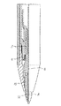
第1参考例を図3に示し説明する。軸筒1には、複数の芯を収容する芯タンク2が前後動可能に配置されている。その芯タンク2の前端には、芯の把持・解放を行うチャック体3が固定されており、そのチャック体3の前方部には、そのチャック体3の開閉を行うチャックリング4が囲繞している。そして、それら芯タンク2やチャック体3は、コイルスプリングなどの弾撥部材5によって後方に付勢されている。尚、芯タンク2の後方には、消しゴム6と、その消しゴム6を覆うようにノックキャップ7が着脱自在に取り付けられている。符号8は、クリップ9を一体に有する外キャップであり、軸筒1の前方部にも着脱できるものとなっている。
一方、その軸筒1の先端には、螺着などの手段によって先部材10が着脱自在に取り付けられており、その先部材10の先端には、芯保護管部11が一体に成形されているが、別部材で構成し、圧入などの手段によって先部材10に固定しても良い。また、その先部材10の内側には、芯を軽く保持し、芯の後退を阻止するゴム状弾性体などから形成された芯保持部材12が圧入された状態で配置されている。この芯保持部材12は、先部材10の中間部から芯保護管部11の先端近傍まで延設・形成されている。即ち、芯保護管部11の先端部は、芯の筆記によるふれを防止するガイド部13となっている。ちなみに、このガイド部13の長手方向の長さは、0.1mm〜2.0mm程度形成されていればよい。例えば、このガイド部13を形成せずに、前記芯保持部12を芯保護管部11の前端部まで形成してしまうと、筆記の際に芯がぐらついてしまい、筆記しにくいものとなってしまう。
【0007】
また、前記芯保持部12の内面には、突起14が長手方向に渡って連続的に形成されているが、部分的に形成しても良い。本例では、3つの突起14が等間隔に長手方向に渡って形成されている(図3参照)が、これに限定されることなく4つや5つ形成しても良いが、極力等間隔に形成するのが好ましい。勿論、突起14の頂部に接する内接円の直径は、使用する芯の直径よりも若干小さなものとなっている。この突起14の弾性変形によって、芯の直径のバラツキを吸収するのである。符号15は、芯保持部材12の上端に形成された円錐孔であって、芯保持部材12に芯を誘導する案内部となっている。
尚、前記突起14に変え、図4に示すように芯保持部材12の内面を6角形や8角形など多角形に形成し、各辺16によって芯を保持しても良い。また、前例では、断面が円弧状の突起としたが、三角形であっても良く、その形状に限定されないものである。
【0008】
第2参考例を図5に示し説明する。芯保護管17を先部材10に対して前後動可能に配置した例である。勿論、この芯保護管17の内側にも前例のような芯保持部材12が配置されているが、芯保護管17の内面に微小な突起を形成するなどして、芯保持部を一体成形するなどしても良い。この場合には、樹脂材質などで成形するのが好ましいが、樹脂材質で成形するのであるならば、前記芯保護管と芯保持部材を、いわいる2色成形やインサート成形と称される成形方法などによって成形しても良い。符号18は、芯保持部材12に芯を誘導するための芯案内部材である。
【0009】
第3参考例を図6に示し説明する。前記第2例の芯保持部材12を芯保護管17のほぼ全域に渡って配置されているが、前述もしたように、芯保護管17の先端内面には、約1.5mm程度の長さのガイド部13が形成されている。また、本例における芯保持部材12の芯を保持する保持力は、芯保護管17の先部材10の内面に対する摺動抵抗力よりも大きく設定されている。即ち、仮に芯が後退しようとすると芯保護管17も後退するようになっている。以下、この機構を活用した動作について説明する。図7は、チャック体3から離れた芯Aが芯保持部材12に保持され、後続する芯Bが芯保持部材12に入り込んだ状態でチャック体3に把持されている。この状態で芯の繰り出し操作を行うと、後続芯Bは芯Aを押圧前進させながら、芯保持部材12を有する芯保護管17をも前進させる。芯の芯保持部材に対する芯保持力の方が大きく設定されているからである。やがて、芯保持部材17の外面段部18が先部材10の内面段部10aに当接し、その芯保護管17の前進移動が阻止される(図8参照)。そして、この時から、芯Aの芯保護管17の先端からの突出が開始され、やがて、チャック体3は後続芯Bを解放する(図9参照)。
【0010】
ここで、芯の繰り出し操作を解除すると、チャック体3などが弾撥部材5によって後方に復帰する。この復帰過程でチャック体3がチャックリング4によって再び閉鎖させられ、後続芯Bを把持するが、完全に把持する直前に後続芯Bを半把持状態で若干後退させる。ここで、一般的なシャープペンシルにあっては、芯Aとの間に若干の隙間が発生し、筆記の際に芯Aが後退してしまいいやな思いをさせられるが、本例においては、後続芯Bが芯保持部材12に保持されているため、後続芯Bと共に、芯保護管17が後退する。即ち、芯Aと後続芯Bとが接触した状態で後退するのである(図10参照)。よって、筆記の際に芯Aが後退することなく、良好な筆記を得ることができる。
【0011】
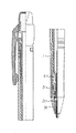
第1例を図11,図12に示し説明する。第3例をさらに向上させた例であり、後続芯Bが芯保持部材12に保持されていない状態においても、芯Aとの間に発生する隙間を防止したものである。以下詳述する。本例の芯保護管20の後部には、筒状部21が形成されており、その筒状部21には窓孔22が対向した位置に形成されている。そして、その窓孔22には、チャック体3の頭部に形成された突起23が遊挿しているが、係合可能なものとなっている。符号24は、Oリングであって、前記先部材10と芯保護管20との間に介在している。先部材10に対する芯保護管20の摺動抵抗が、このOリングによって調整が可能なものとなっている。
動作について説明すると、芯繰り出し操作後、チャック体3が後退する際に、チャック体3の突起23が芯保護管20の窓孔に係合し、その芯保護管20をも後退させる。その結果、後続芯Bを芯Aに接触させた状態で後退させることができる。尚、繰り出し操作時に、芯保護管20の前進移動が規制された状態においても、芯が繰り出されるため、芯保護管20から芯Aを突出させて状態で芯保護管20を後退させることができる。よって、芯Aが再び芯保護管20内に後退してしまうようなことがない。
【0012】
【発明の効果】
本発明は、内部に芯繰り出し機構を有し、その芯繰り出し機構の前方部に芯を保持する芯保持部材が配置されたシャープペンシルであって、その芯保持部材の内面を異形形状にすると共に、その芯保持部材の前端を芯の突出口の先端から若干後退した部位に位置させ、また、前記シャープペンシルの先端に芯保護管を前後動可能に配置すると共に、その芯保護管に前記芯保持部材を取り付け、さらに、前記芯繰り出し機構の少なくとも1部材をチャック体とし、そのチャック体の頭部に突起を形成すると共に、前記芯保護管の後部には筒状部を形成し、その筒状部に窓孔を形成し、その窓孔に前記チャック体の突起を係合させ、その係合動作により前記チャック体の後退動作と連動して芯保護管を後退させたので、芯を有効に活用することができる。
【図面の簡単な説明】
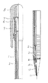
【図1】 第1参考例を示す縦半断面図。
【図2】 図1の要部拡大図。
【図3】 図2の横断面図。
【図4】 芯保持部材の変形例を示す横断面図。
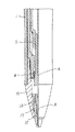
【図5】 第2参考例を示す要部縦半断面図。
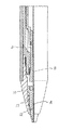
【図6】 第3参考例を示す要部縦半断面図。
【図7】 第3参考例の動作を説明する要部縦半断面図。
【図8】 第3参考例の動作を説明する要部縦半断面図。
【図9】 第3参考例の動作を説明する要部縦半断面図。
【図10】 第3参考例の動作を説明する要部縦半断面図。
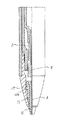
【図11】 第1例を示す縦半断面図。
【図12】 図11の要部拡大図。
【符号の説明】
1 軸筒
2 芯タンク
3 チャック体
4 チャックリング
5 弾撥部材
6 消しゴム
7 ノックキャップ
8 外キャップ
9 クリップ
10 先部材
11 芯保護管部
12 芯保持部材
13 ガイド部
14 突起
15 円錐孔
16 辺
17 芯保護管
18 芯案内部材
19 外面段部
20 芯保護管
21 筒状部
22 窓孔
23 突起
24 Oリング[0001]
BACKGROUND OF THE INVENTION
The present invention relates to a mechanical pencil having a lead feeding mechanism therein and a lead holding member for holding the lead at a front portion of the lead feeding mechanism.
[0002]
[Prior art]
One example is Japanese Utility Model Publication No. 55-23737. The utility model registration claim of that publication includes the following: “In a cylindrical elastic ring with a conical head and a hook-like overhang at the base, an elastic force is applied to the core on the inner periphery of the head. The presser retaining ring in the pencil feeding mechanism characterized by providing a projecting portion to be joined. "FIG. 7 shows an example of its use. More specifically, a retaining ring made of an elastic body is arranged behind the base, but in front of the shaft cylinder, and a plurality of protrusions for holding a pencil lead are formed on the inner surface of the retaining ring. Has been.
[0003]
[Problems to be solved by the invention]
However, in the above-described prior art, even if there is some variation in the diameter of the core, although the protrusion can be reliably held by elastic deformation, it becomes shorter with writing, and it becomes shorter from the protrusion. The detached core fell from the base and could not be used effectively. Specifically, a core of about 8 mm to 15 mm was wasted.
[0004]
[Means for Solving the Problems]
The present invention is a mechanical pencil having a lead feeding mechanism inside, and a lead holding member for holding the lead at the front part of the lead feeding mechanism, wherein the inner surface of the lead holding member has an irregular shape. The front end of the lead holding member is positioned at a position slightly retracted from the tip of the lead protrusion , and a lead protection tube is disposed at the tip of the mechanical pencil so as to be movable back and forth. A holding member is attached, and at least one member of the core feeding mechanism is used as a chuck body. A projection is formed on the head of the chuck body, and a cylindrical portion is formed at the rear of the core protection tube. A gist is that a window hole is formed in the shape portion, the projection of the chuck body is engaged with the window hole, and the core protection tube is retracted in conjunction with the retraction operation of the chuck body by the engaging operation. .
[0005]
[Action]
The lead is held near the tip of the mechanical pencil.
[0006]
【Example】
A first reference example will be described with reference to FIG. A
On the other hand, a
[0007]
Moreover, although the
Instead of the
[0008]
A second reference example will be described with reference to FIG. This is an example in which the
[0009]
A third reference example will be described with reference to FIG. The
[0010]
Here, when the lead feeding operation is canceled, the
[0011]
A first example will be described with reference to FIGS. This is an example in which the third example is further improved, in which a gap generated between the trailing core B and the core A is prevented even when the trailing core B is not held by the
The operation will be described. After the lead-out operation, when the
[0012]
【The invention's effect】
The present invention is a mechanical pencil having a lead feeding mechanism inside, and a lead holding member for holding the lead at the front part of the lead feeding mechanism, wherein the inner surface of the lead holding member has an irregular shape. The front end of the lead holding member is positioned at a position slightly retracted from the tip of the lead protrusion , and a lead protection tube is disposed at the tip of the mechanical pencil so as to be movable back and forth. A holding member is attached, and at least one member of the core feeding mechanism is used as a chuck body. A projection is formed on the head of the chuck body, and a cylindrical portion is formed at the rear of the core protection tube. A window hole is formed in the shaped part, and the protrusion of the chuck body is engaged with the window hole, and the core protection tube is retracted in conjunction with the retracting operation of the chuck body by the engaging operation, so the core is effective Can be used for Kill.
[Brief description of the drawings]
FIG. 1 is a longitudinal half sectional view showing a first reference example .
FIG. 2 is an enlarged view of a main part of FIG.
3 is a cross-sectional view of FIG.
FIG. 4 is a transverse sectional view showing a modification of the core holding member.
FIG. 5 is a longitudinal half sectional view of an essential part showing a second reference example .
FIG. 6 is a longitudinal half sectional view of an essential part showing a third reference example .
FIG. 7 is a longitudinal half sectional view of an essential part for explaining the operation of a third reference example .
FIG. 8 is a longitudinal half sectional view of an essential part for explaining the operation of a third reference example .
FIG. 9 is a longitudinal half sectional view of an essential part for explaining the operation of a third reference example .
FIG. 10 is a longitudinal half sectional view of an essential part for explaining the operation of a third reference example .
FIG. 11 is a longitudinal half sectional view showing a first example .
12 is an enlarged view of a main part of FIG.
[Explanation of symbols]
1
Claims (1)
Priority Applications (1)
| Application Number | Priority Date | Filing Date | Title |
|---|---|---|---|
| JP2001164614A JP4635380B2 (en) | 2001-05-31 | 2001-05-31 | mechanical pencil |
Applications Claiming Priority (1)
| Application Number | Priority Date | Filing Date | Title |
|---|---|---|---|
| JP2001164614A JP4635380B2 (en) | 2001-05-31 | 2001-05-31 | mechanical pencil |
Publications (2)
| Publication Number | Publication Date |
|---|---|
| JP2002356091A JP2002356091A (en) | 2002-12-10 |
| JP4635380B2 true JP4635380B2 (en) | 2011-02-23 |
Family
ID=19007412
Family Applications (1)
| Application Number | Title | Priority Date | Filing Date |
|---|---|---|---|
| JP2001164614A Expired - Fee Related JP4635380B2 (en) | 2001-05-31 | 2001-05-31 | mechanical pencil |
Country Status (1)
| Country | Link |
|---|---|
| JP (1) | JP4635380B2 (en) |
Families Citing this family (1)
| Publication number | Priority date | Publication date | Assignee | Title |
|---|---|---|---|---|
| JP4566717B2 (en) * | 2004-12-01 | 2010-10-20 | 株式会社パイロットコーポレーション | mechanical pencil |
Family Cites Families (5)
| Publication number | Priority date | Publication date | Assignee | Title |
|---|---|---|---|---|
| JPS52102238U (en) * | 1976-01-30 | 1977-08-03 | ||
| JPS5674782U (en) * | 1979-11-14 | 1981-06-18 | ||
| JPH0848098A (en) * | 1993-10-27 | 1996-02-20 | Pentel Kk | Sharp pencil |
| JP3466739B2 (en) * | 1994-10-28 | 2003-11-17 | 株式会社壽 | Mechanical pencil slider |
| JP2001039081A (en) * | 1999-07-29 | 2001-02-13 | Pentel Corp | mechanical pencil |
-
2001
- 2001-05-31 JP JP2001164614A patent/JP4635380B2/en not_active Expired - Fee Related
Also Published As
| Publication number | Publication date |
|---|---|
| JP2002356091A (en) | 2002-12-10 |
Similar Documents
| Publication | Publication Date | Title |
|---|---|---|
| JP3885315B2 (en) | Sharp pencil | |
| JP3882272B2 (en) | Sharp pencil | |
| KR100707156B1 (en) | Mechanical pencil | |
| JP4635380B2 (en) | mechanical pencil | |
| JP2001105783A (en) | Propelling pencil | |
| JPH1148680A (en) | Sharp pencil | |
| JP4419297B2 (en) | Mechanical pencil chuck body | |
| JP3870560B2 (en) | Sharp pencil | |
| JP3982386B2 (en) | mechanical pencil | |
| JP4642271B2 (en) | mechanical pencil | |
| JP2002067574A (en) | Cylindrical body with thin holes | |
| JP3895057B2 (en) | Writing instrument | |
| JP3711701B2 (en) | Sharp pencil | |
| JPS6139594Y2 (en) | ||
| JPH0450158Y2 (en) | ||
| JP4786073B2 (en) | mechanical pencil | |
| JP2004301207A (en) | Rod holder | |
| JPS641108Y2 (en) | ||
| JP2002362090A (en) | Mechanical pencil | |
| JPH09207490A (en) | Mechanical pencil | |
| JP2002362087A (en) | Mechanical pencil | |
| JPS5837666Y2 (en) | Knotsuku style pencil | |
| JPS5845103Y2 (en) | Shape pencil | |
| JP2002321493A (en) | Knock type pencil | |
| JP3931469B2 (en) | mechanical pencil |
Legal Events
| Date | Code | Title | Description |
|---|---|---|---|
| A621 | Written request for application examination |
Free format text: JAPANESE INTERMEDIATE CODE: A621 Effective date: 20070201 |
|
| A977 | Report on retrieval |
Free format text: JAPANESE INTERMEDIATE CODE: A971007 Effective date: 20100114 |
|
| A131 | Notification of reasons for refusal |
Free format text: JAPANESE INTERMEDIATE CODE: A131 Effective date: 20100209 |
|
| A521 | Request for written amendment filed |
Free format text: JAPANESE INTERMEDIATE CODE: A523 Effective date: 20100402 |
|
| TRDD | Decision of grant or rejection written | ||
| A01 | Written decision to grant a patent or to grant a registration (utility model) |
Free format text: JAPANESE INTERMEDIATE CODE: A01 Effective date: 20101026 |
|
| A01 | Written decision to grant a patent or to grant a registration (utility model) |
Free format text: JAPANESE INTERMEDIATE CODE: A01 |
|
| A61 | First payment of annual fees (during grant procedure) |
Free format text: JAPANESE INTERMEDIATE CODE: A61 Effective date: 20101108 |
|
| FPAY | Renewal fee payment (event date is renewal date of database) |
Free format text: PAYMENT UNTIL: 20131203 Year of fee payment: 3 |
|
| R150 | Certificate of patent or registration of utility model |
Ref document number: 4635380 Country of ref document: JP Free format text: JAPANESE INTERMEDIATE CODE: R150 Free format text: JAPANESE INTERMEDIATE CODE: R150 |
|
| LAPS | Cancellation because of no payment of annual fees |