JP4635372B2 - Paper sheet separating and accumulating equipment - Google Patents
Paper sheet separating and accumulating equipment Download PDFInfo
- Publication number
- JP4635372B2 JP4635372B2 JP2001140135A JP2001140135A JP4635372B2 JP 4635372 B2 JP4635372 B2 JP 4635372B2 JP 2001140135 A JP2001140135 A JP 2001140135A JP 2001140135 A JP2001140135 A JP 2001140135A JP 4635372 B2 JP4635372 B2 JP 4635372B2
- Authority
- JP
- Japan
- Prior art keywords
- link
- paper sheet
- lever
- arm
- stud
- Prior art date
- Legal status (The legal status is an assumption and is not a legal conclusion. Google has not performed a legal analysis and makes no representation as to the accuracy of the status listed.)
- Expired - Fee Related
Links
Images

Landscapes
- Conveyance By Endless Belt Conveyors (AREA)
Description
【0001】
【発明の属する技術分野】
本発明は、銀行等の金融機関における自動機コーナや、証券,保険,クレジット会社、デパート,書店等の小売店の自動機コーナ、その他消費者金融の無人端末コーナ、コンビニエンスストアに設置される自動取引装置等に組み込まれる紙葉類分離集積装置に関する。
【0002】
【従来の技術】
この種の紙葉類分離集積装置としては、例えば、図5に示すものがある。
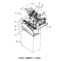
図5は、紙幣入出金機に組み込まれる紙幣分離集積装置の主要部分を示す斜視図である。
図において、1は分離集積部であり、紙幣を分離、集積する駆動部等が収められている。
【0003】
2は、スタッカ部であり、集積された紙幣等が収納される。
3は、ステージであり、このステージ3上に紙幣4を集積させ、図示しない駆動機構により上下動可能になっている。
5は、フィードローラであり、図示しないリバースローラと共に、紙幣を1枚づつ分離して送り出す分離ゲート部を構成している。
【0004】
6は、ピックアップローラであり、ステージ3上の紙幣4を繰り出すためのトリガローラとなっている。
7は、駆動モータであり、後述のサイドフレームに固定されている。
8は、集積した紙幣4をステージ3上に収納するため収納機構である。
9は、サイドフレームであり、収納機構8等の位置を移動させるためのリンク機構が設けられている。
【0005】
図6は、サイドフレーム9に設けられたリンク機構を示す側面図である。
図において、10は駆動アームであり、駆動モータ7の回転軸と連結しており、駆動モータ7により駆動される。
11は、リンク12とリンク13の動きを拡大し保持するためのアームであり、サイドフレーム9に固定されたスタッド14にスナップリング15により回動可能に取り付けられている。
【0006】
リンク12には、スタッド16が固定されており、このスタッド16にレバー11とリンク13がスナップリング17により回動可能に取り付けられている。
また、リンク12は、駆動アーム10に固定されたスタッド18にスナップリング19によって回動可能に取り付けられ、駆動アーム10と連結している。
20は、シーソレバーであり、サイドフレーム9に固定されたスタッド21にスナップリング22により回動可能に取り付けられている。このシーソレバー20の一端には、スタッド23が固定されており、リンク13をスナップリング24で回動可能に取り付けることにより連結している。
【0007】
シーソレバー20の他端には、ポスト25が取り付けられており、このポスト25には、アップレバー26を作動させるためのカムローラ27が回転自在に取り付けられている。
アップレバー26は、支点シャフト28を中心に回動し、収納機構8を移動させるためのアップアーム29が固定されている。このアップレバー26には、切欠き部30が設けられており、カムローラ27が回転しながらこの切欠き部30に沿って移動できるようになっている。
【0008】
31は舌片シャフトであり、図示しない集積用舌片ローラが回転自在に取り付けられており、弾性体を用いた4本乃至それ以上の放射状に伸びた図示しない舌片と連結している。
32はアームであり、ねじ33により舌片シャフト31に固定されている。
34はセンサプレートであり、図示しないねじによりアーム32に調整可能に固定されている。
【0009】
35は、アーム32とセンサレバー36を連結するリンクであり、アーム32とはリンク35に固定された図7に示すスタッド37にスナップリング38により回動可能に取り付けられ、センサレバー36とはセンサレバー36に固定されたスタッド39にスナップリング40により回動可能に取り付けられている。また、このリンク35はフィードローラ5のシャフト41を避ける形状に成形されている。
【0010】
42は、センサレバー36と駆動アーム10とを連結するリンクであり、センサレバー36とはリンク42に固定されたスタッド43にスナップリング44により回動可能に取り付けられ、駆動アーム10とは駆動アーム10に固定されたスタッド45にスナップリング46により回動可能に取り付けられている。
47はセンサ遮断部であり、フォトインタラプタ48がセンサレバー36の動きを検知する用に供される。
【0011】
49、50はフォトインタラプタであり、センサプレート34に設けられた図示しないセンサ遮断部を介してアーム32の動きを検知するために設けられている。
以上の構成を有する従来例の作動を説明する。
図6は、集積時の状態を示し、図7は、分離時と収納時の状態を示しており、集積時には、図7の状態から図6の状態に移行する。
【0012】
図7において、駆動モータ7により駆動アーム10が矢印Aの方向に回転すると、駆動アーム10に固定されたスタッド45と連結している舌片シャフト駆動リンク系のリンク42、センサレバー36、リンク35を介してアーム32が引張られ、アーム32に固定されたセンサプレート34に設けられた図示しないセンサ遮断部がフォトインタラプタ49を遮る位置まで移動する。また、センサレバー36に設けられたセンサ遮断部47は、フォトインタラプタ48を横切り、図6に示す位置まで移動する。
【0013】
これに伴って、図示しない集積用舌片ローラがフィードローラ5に圧接し、図示しない舌片が集積方向に回転する。
この時、駆動アーム10に固定されたスタッド18と連結している収納機構駆動リンク系のリンク12、レバー11、リンク13を介してシーソレバー20に固定されたスタッド23を押し下げ、スタッド21を支点としてシーソレバー20が回動し、アップレバー26に設けられた切欠き部30に沿ってカムローラ27が移動し、切欠き部30から抜け出すことでアップレバー26を上方に持ち上げ、アップレバー26に固定されたアップアーム29を引き上げて収納機構8をピックアップローラ6の上方に退避させる。
【0014】
この過程で、ステージ3が移動し、ステージ上の紙幣4の最上位とピックアップローラ6との間に紙幣を集積できるに充分な空間を確保する。
この状態で、図示しない搬送路から紙幣が給送されると、フィードローラ5とリバースローラで紙幣を受け取り、ステージ3の方向に紙幣4を送り込む。この送り込まれた紙幣4は、舌片によって叩き落とされ、ステージ上の紙幣の上に堆積し集積される。
【0015】
集積した紙幣4を収納するための収納動作の場合は、図6の状態から図7の状態に移行する。
駆動モータ7により駆動アーム10が矢印Bの方向に回転すると、駆動アーム10に固定されたスタッド45と連結している舌片シャフト駆動リンク系のリンク42、センサレバー36、リンク35を介してアーム32が押され、アーム32に固定されたセンサプレート34に設けられた図示しないセンサ遮断部がフォトインタラプタ50を遮る位置まで移動し、図示しない集積用舌片ローラがフィードローラ5から離れ、舌片シャフト31および図示しない舌片が、図示しない走行ガイドから下方に退避する。
【0016】
この時、スタッド18と連結している収納機構駆動リンク系のリンク12、レバー11、リンク13、シーソレバー20を介して、シーソレバー20に固定されたスタッド23を引き上げ、スタッド21を支点としてシーソレバー20が回動し、アップレバー26に沿ってカムローラ27が移動し切欠き部30に嵌り込むことで、収納機構8等の自重によってアップレバー26が下方移動する。
【0017】
これによって、アップレバー26に固定されたアップアーム29に繋がる収納機構8がステージ3上の紙幣4の方向に移動し、ステージ上の紙幣4と収納機構8とを圧接させ、紙幣4を押さえる。
紙幣4を1枚づつ分離し繰り出す分離動作の場合は、ステージ3が上昇し、ピックアップローラ6とステージ上の紙幣4の最上位とを圧接させる。この時、収納機構8がステージ3上の紙幣4の最上位に圧接したまま上昇するため、これに繋がるアップアーム29とアップレバー26を図7に示すCの位置まで押し上げる。
【0018】
分離動作が開始されると、ピックアップローラ6が回転し、ピックアップローラ6とステージ3上の最上位の紙幣4との間の摩擦力によって最上位の紙幣4を一枚フィードローラ6の方向に移送する。移送された紙幣4は、フィードローラ6と図示しないリバースローラによって構成する分離ゲートから図示しない搬送路の方へ送り出される。
【0019】
【発明が解決しようとする課題】
しかしながら、上述した従来の技術においては、分離時には、収納機構がステージ上の紙幣の最上位にある分離紙幣を押さえる状態になっているため、分離の際の分離紙幣と非分離紙幣間の摩擦力が増大し、ピックアップローラと分離紙幣間の摩擦力を上まわり、繰り出し分離不良(空振り)を起こす恐れがある。
【0020】
また、この傾向は、日本銀行にて新規発行された紙幣で帯封した官封券をさばいて繰り出し分離する場合や、ピックアップローラと分離紙幣間の摩擦係数が低下する冬季に顕著になるという問題があった。
本発明は、上記の問題点を解決するためになされたもので、繰り出し分離不良が発生しやすい官封券や冬季であっても、繰り出し分離不良を抑制する手段を提供することを目的としている。
【0021】
【課題を解決するための手段】
本発明は、上記課題を解決するために、搬送路から給送される紙葉類を収納するスタッカ部と、前記スタッカ部に格納され給送された紙葉類を集積する上下動可能なステージと、紙葉類を収納部に繰り出し給送するピックアップローラと、紙葉類を繰り出し給送するフィードローラと、集積された紙葉類を押さえる収納機構とを備える紙葉類分離集積装置において、前記収納機構を移動させるリンク機構に連結する駆動アームと、前記駆動アームを回転駆動する動力源とを有する駆動機構と、前記収納機構を移動させるリンク機構に設けた不作動状態を発生させる摺動孔とを備え、紙葉類の分離時に、前記駆動源によって前記駆動アームを回転作動させ、前記摺動孔によって発生させた前記不作動状態により、前記収納機構を集積紙葉類上から退避させ、紙葉類を順次繰り出すことを特徴とする。
【0022】
【発明の実施の形態】
以下に図面を参照して本発明による紙葉類分離集積装置の実施の形態について説明する。
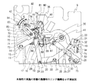
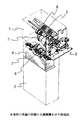
図1は、本発明の第一実施の形態のサイドフレーム9に設けられたリンク機構を示す側面図、図2は、主要構成部品を示す斜視図である。
【0023】
図2において、1は分離集積部であり、紙幣を分離、集積する駆動部等が収められている。
2は、スタッカ部であり、集積された紙幣等が収納される。
3は、ステージであり、このステージ3上に紙幣4を集積させ、図示しない駆動機構により上下動可能になっている。
【0024】
5は、フィードローラであり、図示しないリバースローラと共に、紙幣を1枚づつ分離して送り出す分離ゲート部を構成している。
6は、ピックアップローラであり、ステージ3上の紙幣4を繰り出すためのトリガローラとなっている。
7は、駆動モータであり、後述のサイドフレームに固定されている。
【0025】
8は、集積した紙幣4をステージ3上に収納するため収納機構である。
9は、サイドフレームであり、収納機構8等の位置を移動させるためのリンク機構が設けられている。
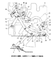
図1において、10は駆動アームであり、駆動モータ7の回転軸と連結しており、駆動モータ7により回転駆動される。
【0026】
11は、リンク12とリンク13の動きを拡大し保持するためのアームであり、サイドフレーム9に固定されたスタッド14にスナップリング15により回動可能に取り付けられている。
リンク12には、スタッド16が固定されており、このスタッド16にレバー11とリンク13がスナップリング17により回動可能に取り付けられている。
また、リンク12は、摺動孔70が設けられており、駆動アーム10に固定されたスタッド71にワッシャ72を介してスナップリング73によって回動および摺動可能に取り付けられ、駆動アーム10と連結している。
【0027】
20は、シーソレバーであり、サイドフレーム9に固定されたスタッド21にスナップリング22により回動可能に取り付けられている。このシーソレバー20の一端には、スタッド23が固定されており、リンク13をスナップリング24で回動可能に取り付けることにより連結している。
シーソレバー20の他端には、ポスト25が取り付けられており、このポスト25には、アップレバー26を作動させるためのカムローラ27が回転自在に取り付けられている。
【0028】
アップレバー26は、支点シャフト28を中心に回動し、収納機構8を移動させるためのアップアーム29が固定されている。このアップレバー26には、切欠き部30が設けられており、カムローラ27が回転しながらこの切欠き部30に沿って移動できるようになっている。
31は舌片シャフトであり、図示しない集積用舌片ローラが回転自在に取り付けられており、弾性体を用いた4本乃至それ以上の放射状に伸びた図示しない舌片と連結している。
【0029】
32はアームであり、ねじ33により舌片シャフト31に固定されている。
34はセンサプレートであり、ねじ74によりアーム32に調整可能に固定されており、センサ遮断部75が設けられている。
35は、アーム32とセンサレバー36を連結するリンクであり、アーム32とはリンク35に固定された図4に示すスタッド37にスナップリング38により回動可能に取り付けられている。
【0030】
リンク35のセンサレバー36側には、摺動孔76が設けられており、センサレバーに固定されたスタッド77にワッシャ78を介してスナップリング79により回動および摺動可能に取り付けられ、センサレバー36と連結している。また、このリンク35はフィードローラ5のシャフト41を避ける形状に成形されている。
【0031】
42は、センサレバー36と駆動アーム10とを連結するリンクであり、センサレバー36とはリンク42に固定されたスタッド80にスナップリング81により回動可能に取り付けられている。
リンク42には、摺動孔82が設けられており、駆動アーム10に固定されたスタッド83にワッシャ84を介してスナップリング85により回動および摺動可能に取り付けられ、駆動アーム10と連結している。
【0032】
86は、バイアススプリングであり、リンク35に設けられた突起87で位置決めされ、突起88で回転を防止し、ねじ89でリンク35に固定されており、センサレバー36をリンク35から遠ざける方向にバイアス力を与えている。
90はセンサ遮断部であり、フォトインタラプタ48がセンサレバー36の動きを検知する用に供される。
【0033】
49、50はフォトインタラプタであり、センサプレート34に設けられたセンサ遮断部75を介してアーム32の動きを検知するために設けられている。
次に上述した構成の作用について説明する。
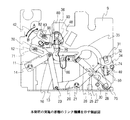
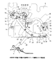
図1は、集積時の状態を示し、図3は分離時、図4は収納時の状態を示しており、集積時には、図4の状態から図1の状態に移行する。
【0034】
図4において、駆動モータ7により駆動アーム10が矢印Aの方向に回転すると、駆動アーム10に固定されているスタッド71とスタッド83は、それぞれリンク12に設けられている摺動孔70内とリンク42に設けられた摺動孔82内とを移動し始め、スタッド71が先に実動領域に達する。
これに伴って、スタッド71と連結している収納機構駆動リンク系のリンク12、レバー11、リンク13を介してシーソレバー20に固定されたスタッド23を押し下げ、スタッド21を支点としてシーソレバー20が回動し、アップレバー26の切欠き部30に沿ってカムローラ27が移動し、切欠き部30から抜け出そうとすることでアップレバー26を上方に持ち上げ、アップレバー26に固定されたアップアーム29が引き上げられて、収納機構8が上方に移動し始める。
【0035】
次いで、駆動アーム10に固定されているスタッド83は、リンク42に設けられた摺動孔82内で実動領域に達し、スタッド83と連結している舌片シャフト駆動リンク系のリンク42、センサレバー36、リンク35を介してアーム32が引張り、アーム32に固定されたセンサプレート34に設けられたセンサ遮断部75がフォトインタラプタ49を遮る位置まで移動させる。
【0036】
これに伴って、図示しない集積用舌片ローラがフィードローラ5に圧接し、図示しない舌片が集積方向に回転する。この時、収納機構8はピックアップローラ6の上方に退避しており、図1に示す状態になっている。
この過程で、ステージ3が移動し、ステージ上の紙幣4の最上位とピックアップローラ6との間に紙幣を集積できるに充分な空間を確保する。
【0037】
この状態で、図示しない搬送路から紙幣が給送されると、フィードローラ5とリバースローラで紙幣を受け取り、ステージ3の方向に紙幣4を送り込む。この送り込まれた紙幣4は、搬入口での滞留を防ぐため舌片によって叩き落とされ、ステージ上の紙幣の上に堆積し集積される。
集積した紙幣4を分離し繰り出す分離動作の場合は、図1の状態から図3の状態に移行する。
【0038】
駆動モータ7により駆動アーム10が矢印Bの方向に回転すると、駆動アーム10に固定されているスタッド83は、リンク42に設けられた摺動孔82内を移動する。
この動きに伴って、スタッド83と連結している舌片シャフト駆動リンク系のリンク42、センサレバー36、リンク35を介してアーム32が押され、アーム32に固定されたセンサプレート34に設けられたセンサ遮断部75がフォトインタラプタ50を遮る位置で、センサレバー36に設けられたセンサ遮断部90がフォトインタラプタ48を遮る位置まで移動する。
【0039】
これに伴って、図示しない集積用舌片ローラがフィードローラ5から離れ、舌片シャフト31および図示しない舌片が、図示しない走行ガイドから下方に退避する。
この時、駆動アーム10に固定されているスタッド71は、リンク12に設けられている摺動孔70内を移動し、スタッド71と連結しているリンク12を回動させる。しかしながら、この移動の間はリンク12の遊びの間であるので、レバー11、リンク13、シーソレバー20に駆動力が伝わらない不作動状態となっている。従って、カムローラ27が移動することはなく、アップレバー26に固定されたアップアーム29は、集積時と同様に引き上げられたままになっており、収納機構8もピックアップローラ6の上方に保持されている。
【0040】
この過程で、ステージ3は上方に移動し、ピックアップローラ6とステージ3上の紙幣4の最上位とを圧接させる。
分離動作が開始されると、ピックアップローラ6が回転し、ピックアップローラ6とステージ3上の最上位の紙幣4との間の摩擦力によって最上位の紙幣4を一枚フィードローラ6の方向に移送する。移送された紙幣4は、フィードローラ6と図示しないリバースローラによって構成する分離ゲートから図示しない搬送路の方へ送り出される。
【0041】
集積した紙幣4を収納するための収納動作の場合は、図3の状態から図4の状態に移行する。
駆動モータ7により駆動アーム10が矢印Bの方向に更に回転すると、駆動アーム10に固定されたスタッド83と連結している舌片シャフト駆動リンク系のリンク42、センサレバー36、リンク35を介してアーム32が更に押され、アーム32は図示しないリミッタによりその移動を停止する。更に駆動アームが回転するとスタッド83も移動するが、この移動量は、センサレバー53に固定されたスタッド77がリンク35に設けられた摺動孔76内をバイアススプリング86のバイアス力に打ち勝って移動することにより吸収し、アーム32に固定されたセンサプレート34がフォトインタラプタ50を遮り、かつセンサレバー36に設けられたセンサ遮断部90がフォトインタラプタ48を通過した状態すなわち透過状態とすることで、舌片シャフト31および図示しない舌片がフィードローラ5から離れ、図示しない走行ガイドから下方に退避する。
【0042】
この時、駆動アーム10に固定されているスタッド71は、リンク12に設けられている摺動孔70内を移動し、リンク12の遊びの領域を通過し実動領域に入り、スタッド71と連結している収納機構駆動リンク系のリンク12、レバー11、リンク13を介して、シーソレバー20に固定されたスタッド23を引き上げ、スタッド21を支点としてシーソレバー20が回動し、アップレバー26に沿ってカムローラ27が移動し、切欠き部30に嵌り込むことで、収納機構8等の自重によってアップレバー26が下方移動する。
【0043】
これによって、アップレバー26に固定されたアップアーム29に繋がる収納機構8がステージ3上の紙幣4の方向に移動し、ステージ上の紙幣4と収納機構8とを圧接させ、紙幣4を押さえる。
【0044】
【発明の効果】
以上説明したように、本発明は、収納機構駆動リンク系に遊びを持たせ、紙幣の分離時に、収納機構を集積紙幣上から退避させる位置をリンク機構の不作動領域とし、収納機構を集積紙幣上に置かないことで、分離紙幣と非分離紙幣間の摩擦力を低減し、分離紙幣とピックアップローラ間の摩擦力を確保することによって、繰り出し分離不良が発生しやすい官封券や冬季であっても、繰り出し分離不良を大幅に抑制できるという効果が得られる。
【0045】
以上は、紙幣を分離集積する場合で説明したが、封筒やチケット等の紙葉類であれば本発明を適応することができ、上記と同様の効果を得ることができる。
【図面の簡単な説明】
【図1】本発明の実施の形態の集積時のリンク機構を示す側面図
【図2】本発明の実施の形態の主要機構を示す斜視図
【図3】本発明の実施の形態の分離時のリンク機構を示す側面図
【図4】本発明の実施の形態の収納時のリンク機構を示す側面図
【図5】従来例の主要機構を示す斜視図
【図6】本発明の集積時のリンク機構を示す側面図
【図7】本発明の分離時、収納時のリンク機構を示す側面図
【符号の説明】
1 分離集積部
2 スタッカ部
3 ステージ
4 紙幣
5 ピックアップローラ
6 フィードローラ
7 駆動モータ
8 集積機構
9 サイドフレーム
10 駆動アーム
13 リンク
20 シーソレバー
26 アップレバー
31 舌片シャフト
32 アーム
35 リンク
36 センサアーム
42 リンク
48,49,50 フォトインタラプタ
70,76,82 摺動孔[0001]
BACKGROUND OF THE INVENTION
The present invention is applied to automatic machine corners in financial institutions such as banks, automatic machine corners in retail stores such as securities, insurance, credit companies, department stores, bookstores, and other unmanned terminal corners in consumer finance and convenience stores. The present invention relates to a paper sheet separating and accumulating apparatus incorporated in a transaction apparatus or the like.
[0002]
[Prior art]
An example of this type of paper sheet separating and accumulating apparatus is shown in FIG.
FIG. 5 is a perspective view showing a main part of the banknote separating and accumulating apparatus incorporated in the banknote depositing and dispensing machine.
In the figure, reference numeral 1 denotes a separating and accumulating unit that houses a driving unit for separating and accumulating banknotes.
[0003]
Reference numeral 5 denotes a feed roller which, together with a reverse roller (not shown), constitutes a separation gate portion that separates and feeds banknotes one by one.
[0004]
A
A
[0005]
FIG. 6 is a side view showing the link mechanism provided on the
In the figure,
[0006]
A
The
[0007]
A
The up
[0008]
[0009]
A
[0010]
A
[0011]
The operation of the conventional example having the above configuration will be described.
FIG. 6 shows a state at the time of integration, and FIG. 7 shows a state at the time of separation and a storage. The state at the time of integration shifts from the state of FIG. 7 to the state of FIG.
[0012]
In FIG. 7, when the
[0013]
Accordingly, an accumulation tongue piece roller (not shown) presses against the feed roller 5 and the tongue piece (not shown) rotates in the accumulation direction.
At this time, the
[0014]
In this process, the
In this state, when a bill is fed from a conveyance path (not shown), the bill is received by the feed roller 5 and the reverse roller, and the bill 4 is fed in the direction of the
[0015]
In the case of the storing operation for storing the accumulated bills 4, the state shifts from the state of FIG. 6 to the state of FIG. 7.
When the
[0016]
At this time, the
[0017]
Accordingly, the
In the case of the separation operation in which the banknotes 4 are separated and fed out one by one, the
[0018]
When the separation operation is started, the
[0019]
[Problems to be solved by the invention]
However, in the above-described conventional technology, at the time of separation, since the storage mechanism is in a state of pressing the separated bill on the top of the bill on the stage, the frictional force between the separated bill and the non-separated bill at the time of separation. May increase, exceeding the frictional force between the pickup roller and the separated banknote, and may cause feeding separation failure (blank swing).
[0020]
In addition, this tendency becomes prominent in the case of handling and separating government sealed tickets wrapped with banknotes newly issued by the Bank of Japan, and in the winter when the coefficient of friction between the pickup roller and the separated banknotes decreases. there were.
The present invention has been made to solve the above-described problems, and an object of the present invention is to provide means for suppressing a feeding separation failure even in a government seal or a winter season in which a feeding separation failure is likely to occur. .
[0021]
[Means for Solving the Problems]
In order to solve the above-described problems, the present invention provides a stacker unit that stores paper sheets fed from a conveyance path, and a vertically movable stage that accumulates the paper sheets stored and fed in the stacker unit. And a paper sheet separating and accumulating apparatus comprising: a pickup roller that feeds and feeds paper sheets to a storage unit; a feed roller that feeds and feeds paper sheets; and a storage mechanism that holds the accumulated paper sheets. A drive mechanism having a drive arm coupled to a link mechanism for moving the storage mechanism; a power source for rotationally driving the drive arm; and a slide for generating an inoperative state provided in the link mechanism for moving the storage mechanism and a hole, when the separation of the sheets, by the driving source is rotated actuating said drive arm, by the inoperative state caused by the sliding hole, or on an integrated paper sheet to the storage mechanism Retracted, characterized in that for feeding the paper sheets sequentially.
[0022]
DETAILED DESCRIPTION OF THE INVENTION
Embodiments of a paper sheet separating and accumulating apparatus according to the present invention will be described below with reference to the drawings.
FIG. 1 is a side view showing a link mechanism provided in the
[0023]
In FIG. 2, reference numeral 1 denotes a separation / stacking unit that houses a drive unit for separating and stacking banknotes.
[0024]
Reference numeral 5 denotes a feed roller which, together with a reverse roller (not shown), constitutes a separation gate portion that separates and feeds banknotes one by one.
A
[0025]
A
In FIG. 1,
[0026]
A
The
[0027]
A
[0028]
The up
[0029]
A
[0030]
A
[0031]
A
The
[0032]
[0033]
Next, the operation of the above configuration will be described.
FIG. 1 shows a state at the time of integration, FIG. 3 shows a state at the time of separation, and FIG. 4 shows a state at the time of storage. The state at the time of integration shifts from the state of FIG.
[0034]
In FIG. 4, when the
Along with this, the
[0035]
Next, the
[0036]
Accordingly, an accumulation tongue piece roller (not shown) presses against the feed roller 5 and the tongue piece (not shown) rotates in the accumulation direction. At this time, the
In this process, the
[0037]
In this state, when a bill is fed from a conveyance path (not shown), the bill is received by the feed roller 5 and the reverse roller, and the bill 4 is fed in the direction of the
In the case of the separating operation for separating and feeding the accumulated banknotes 4, the state shifts from the state of FIG. 1 to the state of FIG. 3.
[0038]
When the
Along with this movement, the
[0039]
Along with this, the tongue piece roller for accumulation (not shown) is separated from the feed roller 5, and the
At this time, the
[0040]
In this process, the
When the separation operation is started, the
[0041]
In the case of the storing operation for storing the accumulated bills 4, the state shifts from the state of FIG. 3 to the state of FIG. 4.
When the
[0042]
At this time, the
[0043]
Accordingly, the
[0044]
【The invention's effect】
As described above, according to the present invention, the storage mechanism drive link system has a play, and when the banknotes are separated, the position where the storage mechanism is retracted from the stacked banknote is defined as a non-operation area of the link mechanism, and the storage mechanism is the stacked banknote. By not placing it on top, it reduces the frictional force between separated and non-separated banknotes, and secures the frictional force between the separated banknotes and the pick-up roller. However, the effect that the feeding separation failure can be greatly suppressed can be obtained.
[0045]
The above has been described in the case of separating and accumulating banknotes. However, the present invention can be applied to paper sheets such as envelopes and tickets, and the same effects as described above can be obtained.
[Brief description of the drawings]
FIG. 1 is a side view showing a link mechanism during integration according to an embodiment of the present invention. FIG. 2 is a perspective view showing main mechanisms according to an embodiment of the present invention. FIG. 4 is a side view showing the link mechanism during storage according to the embodiment of the present invention. FIG. 5 is a perspective view showing the main mechanism of the conventional example. FIG. Side view showing the link mechanism [FIG. 7] Side view showing the link mechanism during separation and storage of the present invention [Explanation of symbols]
DESCRIPTION OF SYMBOLS 1 Separation / stacking
Claims (2)
前記収納機構を移動させるリンク機構に連結する駆動アームと、前記駆動アームを回転駆動する動力源とを有する駆動機構と、前記収納機構を移動させるリンク機構に設けた不作動状態を発生させる摺動孔とを備え、
紙葉類の分離時に、前記駆動源によって前記駆動アームを回転作動させ、前記摺動孔によって発生させた前記不作動状態により、前記収納機構を集積紙葉類上から退避させ、紙葉類を順次繰り出すことを特徴とする紙葉類分離集積装置。A stacker section for accommodating the paper sheet fed from the transport path, and vertically movable stage for integrating the stored feed has been paper sheet to the stacker unit, feed feeding a paper sheet in the housing portion a pickup roller for the feed roller for feeding feed the paper sheet, the paper sheet separating and accumulating apparatus and a receiving mechanism for pressing the integrated paper sheet,
A drive mechanism having a drive arm coupled to a link mechanism for moving the storage mechanism; a power source for rotationally driving the drive arm; and a slide for generating an inoperative state provided in the link mechanism for moving the storage mechanism With holes ,
During separation of the sheets, by the driving source is rotated actuating said drive arm, by the inoperative state caused by the sliding hole, by removing all the receiving mechanism from the integrated paper sheet, the paper sheet A paper sheet separating and accumulating apparatus characterized by sequentially feeding out the sheets.
前記駆動アームに、集積時に紙葉類の詰まりを防止するための舌片シャフトを移動させるリンク機構と、前記収納機構を移動させるリンク機構とを連結させたことを特徴とする紙葉類分離集積装置。In claim 1 ,
Separating and stacking paper sheets, wherein a link mechanism for moving a tongue shaft for preventing jamming of paper sheets during stacking and a link mechanism for moving the storage mechanism are connected to the drive arm. apparatus.
Priority Applications (1)
| Application Number | Priority Date | Filing Date | Title |
|---|---|---|---|
| JP2001140135A JP4635372B2 (en) | 2001-05-10 | 2001-05-10 | Paper sheet separating and accumulating equipment |
Applications Claiming Priority (1)
| Application Number | Priority Date | Filing Date | Title |
|---|---|---|---|
| JP2001140135A JP4635372B2 (en) | 2001-05-10 | 2001-05-10 | Paper sheet separating and accumulating equipment |
Publications (2)
| Publication Number | Publication Date |
|---|---|
| JP2002332169A JP2002332169A (en) | 2002-11-22 |
| JP4635372B2 true JP4635372B2 (en) | 2011-02-23 |
Family
ID=18986791
Family Applications (1)
| Application Number | Title | Priority Date | Filing Date |
|---|---|---|---|
| JP2001140135A Expired - Fee Related JP4635372B2 (en) | 2001-05-10 | 2001-05-10 | Paper sheet separating and accumulating equipment |
Country Status (1)
| Country | Link |
|---|---|
| JP (1) | JP4635372B2 (en) |
Families Citing this family (2)
| Publication number | Priority date | Publication date | Assignee | Title |
|---|---|---|---|---|
| JP4382644B2 (en) * | 2004-11-24 | 2009-12-16 | 日本電気株式会社 | Paper sheet supply apparatus and paper sheet supply method |
| KR101419047B1 (en) * | 2013-04-23 | 2014-07-11 | 기산전자 주식회사 | Apparatus for processing bill |
Family Cites Families (4)
| Publication number | Priority date | Publication date | Assignee | Title |
|---|---|---|---|---|
| JPS60202024A (en) * | 1984-03-23 | 1985-10-12 | Hitachi Ltd | Banknote stacking and separating device |
| JP2565778Y2 (en) * | 1992-12-16 | 1998-03-18 | 沖電気工業株式会社 | Paper sheet stacking mechanism and paper sheet separating and feeding apparatus |
| JP2818105B2 (en) * | 1993-12-22 | 1998-10-30 | ローレルバンクマシン株式会社 | Paper sheet storage and delivery mechanism in paper sheet depositing and dispensing machine |
| JP3630988B2 (en) * | 1998-06-23 | 2005-03-23 | グローリー工業株式会社 | Paper sheet storage and feeding device |
-
2001
- 2001-05-10 JP JP2001140135A patent/JP4635372B2/en not_active Expired - Fee Related
Also Published As
| Publication number | Publication date |
|---|---|
| JP2002332169A (en) | 2002-11-22 |
Similar Documents
| Publication | Publication Date | Title |
|---|---|---|
| US7942401B2 (en) | ATM equipped with structure for preventing rotation of stack roller | |
| JP5774393B2 (en) | Medium storage device | |
| JP4635372B2 (en) | Paper sheet separating and accumulating equipment | |
| GB2198122A (en) | Sheet store loading apparatus | |
| JP2002321862A (en) | Paper sheet delivering accumulating device | |
| JPS6288737A (en) | Paper sheet processing equipment | |
| JP2587519B2 (en) | Reject mechanism of banknote dispenser | |
| JP7288421B2 (en) | Accumulator/Separator | |
| JPH08310672A (en) | Medium feeding device and medium processing device | |
| JP6536071B2 (en) | Medium feeding cassette and medium delivery device | |
| JP2601032Y2 (en) | Paper sheet separation device | |
| JP3060151B2 (en) | Paper sheet separation and feeding mechanism | |
| JPS63267625A (en) | Paper sheet processing equipment | |
| JPS61127557A (en) | Paper sheet stacking device | |
| JPS59172335A (en) | paper processing equipment | |
| JP2598427Y2 (en) | Stacker stage mechanism | |
| JPS61130133A (en) | Paper sheet handling equipment | |
| JPS61127533A (en) | Automatic paper sheet handler | |
| JPH0312016B2 (en) | ||
| JP2603405Y2 (en) | Bill holding mechanism of bill receiving / dispensing device | |
| JPH0312036B2 (en) | ||
| JP2003276931A (en) | Medium processor | |
| JPS5974830A (en) | Paper sheet separation device | |
| JPS61127542A (en) | Automatic paper sheet handler | |
| JPS61130131A (en) | Sheet handling device |
Legal Events
| Date | Code | Title | Description |
|---|---|---|---|
| A621 | Written request for application examination |
Free format text: JAPANESE INTERMEDIATE CODE: A621 Effective date: 20080104 |
|
| A977 | Report on retrieval |
Free format text: JAPANESE INTERMEDIATE CODE: A971007 Effective date: 20100803 |
|
| A131 | Notification of reasons for refusal |
Free format text: JAPANESE INTERMEDIATE CODE: A131 Effective date: 20100810 |
|
| A521 | Request for written amendment filed |
Free format text: JAPANESE INTERMEDIATE CODE: A523 Effective date: 20101004 |
|
| TRDD | Decision of grant or rejection written | ||
| A01 | Written decision to grant a patent or to grant a registration (utility model) |
Free format text: JAPANESE INTERMEDIATE CODE: A01 Effective date: 20101026 |
|
| A01 | Written decision to grant a patent or to grant a registration (utility model) |
Free format text: JAPANESE INTERMEDIATE CODE: A01 |
|
| A61 | First payment of annual fees (during grant procedure) |
Free format text: JAPANESE INTERMEDIATE CODE: A61 Effective date: 20101108 |
|
| FPAY | Renewal fee payment (event date is renewal date of database) |
Free format text: PAYMENT UNTIL: 20131203 Year of fee payment: 3 |
|
| R150 | Certificate of patent or registration of utility model |
Ref document number: 4635372 Country of ref document: JP Free format text: JAPANESE INTERMEDIATE CODE: R150 Free format text: JAPANESE INTERMEDIATE CODE: R150 |
|
| FPAY | Renewal fee payment (event date is renewal date of database) |
Free format text: PAYMENT UNTIL: 20131203 Year of fee payment: 3 |
|
| S531 | Written request for registration of change of domicile |
Free format text: JAPANESE INTERMEDIATE CODE: R313531 |
|
| FPAY | Renewal fee payment (event date is renewal date of database) |
Free format text: PAYMENT UNTIL: 20131203 Year of fee payment: 3 |
|
| R350 | Written notification of registration of transfer |
Free format text: JAPANESE INTERMEDIATE CODE: R350 |
|
| LAPS | Cancellation because of no payment of annual fees |