JP4635176B2 - Wheelchair lift device and wheelchair lift equipped with the same - Google Patents

Wheelchair lift device and wheelchair lift equipped with the same Download PDF

Info

Publication number
JP4635176B2
JP4635176B2 JP2004030368A JP2004030368A JP4635176B2 JP 4635176 B2 JP4635176 B2 JP 4635176B2 JP 2004030368 A JP2004030368 A JP 2004030368A JP 2004030368 A JP2004030368 A JP 2004030368A JP 4635176 B2 JP4635176 B2 JP 4635176B2
Authority
JP
Japan
Prior art keywords
safety device
elevating
wheelchair
limit switch
contact
Prior art date
Legal status (The legal status is an assumption and is not a legal conclusion. Google has not performed a legal analysis and makes no representation as to the accuracy of the status listed.)
Expired - Fee Related
Application number
JP2004030368A
Other languages
Japanese (ja)
Other versions
JP2005219882A (en
Inventor
秀樹 川端
Original Assignee
株式会社いうら
Priority date (The priority date is an assumption and is not a legal conclusion. Google has not performed a legal analysis and makes no representation as to the accuracy of the date listed.)
Filing date
Publication date
Application filed by 株式会社いうら filed Critical 株式会社いうら
Priority to JP2004030368A priority Critical patent/JP4635176B2/en
Publication of JP2005219882A publication Critical patent/JP2005219882A/en
Application granted granted Critical
Publication of JP4635176B2 publication Critical patent/JP4635176B2/en
Anticipated expiration legal-status Critical
Expired - Fee Related legal-status Critical Current

Links

Images

Landscapes

  • Apparatus For Radiation Diagnosis (AREA)
  • Invalid Beds And Related Equipment (AREA)

Description

本願発明は、車椅子用昇降機における安全装置に関するものである。   The present invention relates to a safety device in an elevator for a wheelchair.

従来の技術では、支持枠に、車椅子が搭乗する搭乗台を昇降可能に設け、搭乗台に一体連接した昇降枠と支持枠とを油圧シリンダを介して連結し、段差の低位置部分と高位置部分とにわたって、搭乗台を昇降できるように構成し、段差を上り下りできるようにした車椅子用昇降機がある。また、この車椅子用昇降機には、支持枠に備えられた第1のリミットスイッチの接点が入ると搭乗台の上昇を停止し、搭乗台に備えられた第2あるいは第3のリミットスイッチの接点が、センサー部材に障害物が接当することで入ると、搭乗台の下降を停止させる駆動制御系が具備されている。   In the conventional technology, a boarding table on which a wheelchair is mounted is provided on the support frame so as to be able to move up and down, and the lifting frame integrally connected to the boarding table and the support frame are connected via a hydraulic cylinder, and the low position portion and the high position of the step are connected. There is a wheelchair elevator that is configured so that the boarding platform can be raised and lowered over the portion, and the level difference can be raised and lowered. In addition, when the contact of the first limit switch provided on the support frame enters the wheelchair elevator, the lift of the boarding stop is stopped, and the contact of the second or third limit switch provided on the boarding base is stopped. A drive control system is provided for stopping the descending of the boarding board when an obstacle comes into contact with the sensor member.

この技術によると、第1のリミットスイッチが故障すると、支持枠のガイド枠から昇降枠に備えられているガイドローラが外れてしまう恐れがある。また、第2及び第3のリミットスイッチが故障すると、搭乗台と支持枠が接触して、車椅子用昇降機の昇降する部材が機械的に昇降できなくなってしまったり、さらには、車椅子用昇降機の第2及び第3のリミットスイッチ以外の構成部材を破損したりしてしまう恐れがある。
特開2000−118971号公報
According to this technique, when the first limit switch breaks down, there is a possibility that the guide roller provided in the elevating frame is detached from the guide frame of the support frame. In addition, if the second and third limit switches fail, the boarding platform and the support frame come into contact with each other, and the members that move up and down the wheelchair elevator cannot be moved up and down mechanically. There is a risk of damaging components other than the second and third limit switches.
JP 2000-118971 A

そこで、本願発明は上記事情を鑑み、昇降部材の位置を検出するとともに、昇降部材の昇降可能範囲を定める位置検出手段が故障しても、車椅子用昇降機の昇降する部材が機械的に昇降できなくなることを防止できる車椅子用昇降機の安全装置を提供することを課題とする。   Therefore, in view of the above circumstances, the present invention detects the position of the elevating member and even if the position detecting means for determining the elevating range of the elevating member breaks down, the elevating member of the wheelchair elevator cannot mechanically elevate. It is an object of the present invention to provide a safety device for a wheelchair elevator that can prevent this.

請求項1の発明は、少なくとも設置面(G)に配設されるベースフレーム(2)と、このベースフレーム(2)に立設される一対の支柱(3),(3)と、該支柱(3),(3)の上部を繋ぐ連結部材(8)と、前記支柱(3),(3)に沿って上下に移動する昇降部材(4)と、この昇降部材(4)に取付けられ車椅子(W)が搭乗可能かつ通過可能なテーブル部(5)と、前記昇降部材(4)前記支柱(3),(3)に沿って上下に昇降させる昇降手段(6)と、前記昇降部材(4)の上限位置と下限位置をそれぞれ検知することにより前記テーブル部(5)の昇降範囲を設定することができる位置検出手段(24)とを具備する車椅子用昇降機(1)において、前記連結部材(8)の下面を覆う状態で上下に揺動自在に取付けた接触プレート(38)と、該接触プレート(38)の上方揺動により作動するリミットスイッチ(39),(39)とからなる安全装置(9)と、前記テーブル部(5)の下面を覆う状態で上下に揺動自在に取付けた接触プレート(29),・・・,(33)と、該接触プレート(29),・・・,(33)の上方揺動により作動するリミットスイッチ(34),(34),・・・とからなる安全装置(7)を設け、前記位置検出手段(24)による昇降範囲に係わらず、安全装置(9)のリミットスイッチ(39)が作動したときにはテーブル部(5)の上昇が停止され下降操作のみ可能となるよう構成し、安全装置(7)のリミットスイッチ(34)が作動したときにはテーブル部(5)の下降が停止され上昇操作のみ可能となるよう構成したことを特徴とする。
請求項2の発明は、前記安全装置(9)において、前記昇降部材(4)あるいは前記テーブル部(5)等の昇降する部材と、前記支柱(3),(3)あるいは前記連結部材(8)等の昇降しない部材との間でメカロックする前に、前記昇降する部材または前記昇降部材(4)に止着した押圧子(42)が前記接触プレート(38)を押し上げ、リミットスイッチ(39)を作動させることにより上昇動作を停止させるように構成したことを特徴とする。
請求項3の発明は、前記安全装置(7)において、前記昇降部材(4)あるいは前記テーブル部(5)等の昇降する部材と、前記支柱(3),(3)あるいは前記ベースフレーム(2)等の昇降しない部材との間でメカロックする前に、前記ベースフレーム(2)あるいは設置面(G)が前記接触プレート(29),・・・,(33)の何れかを押し上げ、リミットスイッチ(34)を作動させることにより下降動作を停止させるように構成したことを特徴とする。
The invention of claim 1 includes at least a base frame (2) disposed on the installation surface (G) , a pair of columns (3), (3) erected on the base frame (2) , and the columns (3), a connecting member (8) that connects the upper parts of ( 3), a lifting member (4) that moves up and down along the pillars (3), (3) , and the lifting member (4). Wheelchair (W) boarding possible and passable table part (5), said post said elevating member (4) (3), an elevating means for elevating up and down along the (3) (6), the lifting member (4) of the upper limit position and the table part by the lower limit position detecting respectively (5) of the lifting range position detecting means it can be set (24) and wheelchair elevator comprising a (1), wherein Contact mounted so that it can swing up and down while covering the lower surface of the connecting member (8) A safety device (9) comprising a rate (38) and limit switches (39), (39) which are operated by swinging the contact plate (38) upward, and a state in which the lower surface of the table portion (5) is covered. Contact plates (29),..., (33) mounted so as to be swingable up and down, and limit switches (34) that are operated by swinging the contact plates (29),. (34),... Is provided, and when the limit switch (39) of the safety device (9) is actuated regardless of the elevation range by the position detecting means (24), the table portion ( 5) The raising is stopped and only the lowering operation is possible, and when the limit switch (34) of the safety device (7) is operated, the lowering of the table portion (5) is stopped and only the raising operation is possible. Shi It is characterized in.
The invention according to claim 2 is characterized in that, in the safety device (9), the elevating member (4) or the table portion (5) or the like elevating member, the struts (3), (3) or the connecting member (8). ) Etc. before mechanically locking with a member that does not move up and down, the pressing member (42) fixed to the member to be moved up or down or the lifting member (4) pushes up the contact plate (38), and the limit switch (39) It is characterized in that the ascending motion is stopped by actuating .
According to the invention of claim 3, in the safety device (7), the elevating member (4) or the table portion (5) or the like elevating member, the support columns (3), (3) or the base frame (2) ) Etc. before mechanically locking with a member that does not move up and down, the base frame (2) or the installation surface (G) pushes up any of the contact plates (29),. The descent operation is stopped by operating (34) .

請求項1の発明によれば、安全装置(9)は、接触プレート(38)が支柱(3),(3)の上部に取付けられた連結部材(8)の下面を覆う状態で上下動可能に取付けられている。したがって、テーブル部(5)の上昇に伴って前記接触プレート(38)に異物が接触し、接触プレート(38)を押し上げると、リミットスイッチ(39)が作動するように構成されている。そして、リミットスイッチ(39)が作動すると、テーブル部(5)の上昇動作を停止させるとともに、上昇動作をさせる指示を受付けない状態となるようにされている。なお、この安全装置(9)が作動中でも、テーブル部(5)の下降動作は可能な状態とされている。そして、接触プレート(38)と異物との接触が解除され、リミットスイッチ(39)が復帰すると、テーブル部(5)が昇降可能な状態に戻るように構成されている。また、安全装置(7)は、各接触プレート(29),・・・,(33)がテーブル部(5)の下面を覆う状態で上下動可能に取付けられている。したがって、テーブル部(5)の下降に伴って前記接触プレート(29),・・・,(33)の何れかに異物が接触し、その接触プレートを相対的に押し上げると、その接触プレートに対応したリミットスイッチ(34)が作動するように構成されている。そして、その接触プレートに対応した少なくとも一つのリミットスイッチ(34)が作動すると、テーブル部(5)の下降動作を停止させるとともに、下降動作させる支持を受付けない状態となるようにされている。なお、この安全装置(7)が作動中でも、テーブル部(5)の上昇動作は可能な状態とされている。そして、接触プレートと異物との接触が解除され、リミットスイッチ(34)が復帰すると、テーブル部(5)が昇降可能な状態に戻るように構成されている。これらの安全装置(7),(9)によって、前記昇降部材(4)や前記テーブル部(5)が昇降する際に、異物等の挟み込みによる破損や怪我を防止することができる。
また、請求項2の発明によれば、位置検出手段(24)が故障した場合であっても、安全装置(9)が作動するように構成しているので、メカロックする前に上昇動作を停止することができ、本体の破損を防止することができる。
さらに、請求項3の発明によれば、位置検出手段(24)が故障した場合であっても、安全装置(7)が作動するように構成しているので、メカロックする前に下降動作を停止することができ、本体の破損を防止することができる。
According to the invention of claim 1, the safety device (9) can be moved up and down in a state where the contact plate (38) covers the lower surface of the connecting member (8) attached to the upper part of the support columns (3) and (3). Installed on. Therefore, the limit switch (39) is configured to operate when a foreign object comes into contact with the contact plate (38) as the table portion (5) rises and pushes up the contact plate (38). When the limit switch (39) is actuated, the ascending operation of the table portion (5) is stopped and the instruction to perform the ascending operation is not accepted. Even when the safety device (9) is in operation, the table portion (5) can be lowered. When the contact between the contact plate (38) and the foreign matter is released and the limit switch (39) is restored, the table portion (5) returns to a state where it can be raised and lowered. In addition, the safety device (7) is attached such that each contact plate (29),..., (33) can move up and down with the lower surface of the table portion (5) covered. Therefore, when a foreign object comes in contact with any one of the contact plates (29),..., (33) as the table portion (5) is lowered, and the contact plate is pushed up relatively, it corresponds to the contact plate. The limit switch (34) is configured to operate. When at least one limit switch (34) corresponding to the contact plate is activated, the lowering operation of the table portion (5) is stopped and the support for the lowering operation is not received. Even when the safety device (7) is in operation, the table section (5) can be raised. When the contact between the contact plate and the foreign matter is released and the limit switch (34) is restored, the table portion (5) returns to a state where it can be raised and lowered. These safety devices (7) and (9) can prevent breakage or injury due to the trapping of foreign substances or the like when the elevating member (4) or the table portion (5) is raised or lowered.
According to the invention of claim 2, even if the position detecting means (24) is out of order, the safety device (9) is configured to operate, so that the ascending operation is stopped before the mechanical lock. It is possible to prevent the main body from being damaged.
Further, according to the invention of claim 3, even if the position detecting means (24) is out of order, the safety device (7) is configured to operate, so the lowering operation is stopped before the mechanical lock. It is possible to prevent the main body from being damaged.

異物が接触プレートに接触するとリミットスイッチが作動し、昇降手段により支柱に沿って上下に昇降する昇降部材の上昇動作を停止させる安全装置を、前記支柱間を連結する連結部材に具備させる。そして、この安全装置を、前記昇降部材の位置を検出するとともに、昇降部材の昇降可能範囲を定める位置検出手段の故障時における補助装置として作用するようにもする。また、異物が接触プレートに接触するとリミットスイッチが作動し、昇降部材の下降動作を停止させる安全装置を、昇降部材に取付けられるテーブル部に具備させる。そして、この安全装置を、前記位置検出手段の故障時における補助装置として作用するようにもする。すなわち、前記位置検出手段が故障して、テーブル部が上限位置あるいは下限位置から車椅子昇降機の昇降する部材が機械的に昇降できなくなる位置まで上昇あるいは下降する間に、前記安全装置が異物の存在に関係なく作動するようにし、テーブル部の上昇あるいは下降動作が停止されるようにする。 When the foreign object comes into contact with the contact plate, the limit switch is activated, and a connecting device that connects the columns is provided with a safety device that stops the lifting operation of the lifting member that moves up and down along the columns by the lifting unit. The safety device detects the position of the elevating member and acts as an auxiliary device in the event of failure of the position detecting means that determines the elevating range of the elevating member. Further, when the foreign object comes into contact with the contact plate, the limit switch is activated, and a safety device for stopping the descending operation of the elevating member is provided on the table portion attached to the elevating member. And this safety device is made to act as an auxiliary device at the time of failure of the position detecting means. That is, while the position detecting means breaks down and the table portion is raised or lowered from the upper limit position or the lower limit position to a position where the member for raising and lowering the wheelchair elevator cannot be lifted or lowered mechanically, The table is operated regardless of whether the table portion is raised or lowered.

これによると、例え位置検出手段が故障しても、安全装置により車椅子用昇降機の昇降する部材が機械的に昇降できなくなることを防止でき、車椅子用昇降機の他の部材が破損したり故障したりすることを防止することができる。また、テーブル部とベースフレームあるいは設置面、前記連結部材とテーブル部あるいは昇降部材の間で、異物を押し潰すことを防止でき、車椅子用昇降機が破損することを防止することができる。さらに、安全装置を位置検出手段の故障時における補助装置としても作用するようにしたことで、位置検出手段の故障時における補助装置を別に設ける必要がなく、車椅子用昇降機を安価に構成することができる。   According to this, even if the position detecting means breaks down, it is possible to prevent the member that moves up and down of the wheelchair elevator from being lifted mechanically by the safety device, and other members of the wheelchair elevator can be damaged or broken. Can be prevented. Further, it is possible to prevent crushing of foreign matter between the table portion and the base frame or the installation surface, and between the connecting member and the table portion or the lifting member, and it is possible to prevent the elevator for the wheelchair from being damaged. Further, since the safety device also functions as an auxiliary device in the event of failure of the position detection means, it is not necessary to separately provide an auxiliary device in the event of failure of the position detection means, and the elevator for a wheelchair can be configured at low cost. it can.

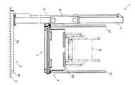
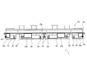
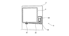
本願発明にかかる安全装置を具備する車椅子用昇降機の一実施例を図面に基づいて説明する。第1図は車椅子用昇降機を示す全体正面図である。第2図はその全体側断面図である。第3図は車椅子用昇降機の動作する様子を示す説明図である。第4図はテーブル部側の安全装置の構成を示す説明図である。第5図はその安全装置を示す側断面図である。第6図はその安全装置を示す部分断面図である。第7図は連結部材側の安全装置の構成を示す説明図である。第8図はその安全装置を示す断面図である。第9図はテーブル部側の安全装置の作動する様子を示す説明図である。第10図は連結部材側の安全装置の作動する様子を示す説明図である。   An embodiment of a wheelchair elevator equipped with a safety device according to the present invention will be described with reference to the drawings. FIG. 1 is an overall front view showing a lift for a wheelchair. FIG. 2 is a sectional side view of the whole. FIG. 3 is an explanatory view showing the operation of the wheelchair elevator. FIG. 4 is an explanatory view showing the structure of the safety device on the table side. FIG. 5 is a side sectional view showing the safety device. FIG. 6 is a partial sectional view showing the safety device. FIG. 7 is an explanatory view showing the configuration of the safety device on the connecting member side. FIG. 8 is a sectional view showing the safety device. FIG. 9 is an explanatory view showing the operation of the safety device on the table side. FIG. 10 is an explanatory view showing the operation of the safety device on the connecting member side.

この車椅子用昇降機1は、ベースフレーム2と、このベースフレーム2に立設される支柱3,3と、この支柱3,3に沿って上下に移動する昇降部材4と、この昇降部材4に取付けられ車椅子Wが搭乗可能かつ通過可能なテーブル部5と、前記昇降部材4を支柱3,3に沿って上下に昇降させる昇降手段6とから主に構成されている。また、この車椅子用昇降機1には、前記テーブル部5下面とベースフレーム2あるいは車椅子用昇降機1の設置面Gとの間で異物を押し潰すことを防止する安全装置7と、前記支柱3,3間を連結する連結部材8と昇降部材4あるいはテーブル部5との間で異物を押し潰すことを防止する安全装置9が具備されている。   The wheelchair elevator 1 is attached to a base frame 2, support columns 3 and 3 erected on the base frame 2, a lifting member 4 that moves up and down along the support columns 3 and 3, and the lifting member 4. The table portion 5 on which the wheelchair W can be mounted and passed, and the elevating means 6 for elevating the elevating member 4 up and down along the support columns 3 and 3 are mainly configured. The wheelchair elevator 1 includes a safety device 7 that prevents crushing of foreign matter between the lower surface of the table portion 5 and the base frame 2 or the installation surface G of the wheelchair elevator 1, and the support columns 3, 3. A safety device 9 is provided to prevent crushing of foreign matter between the connecting member 8 and the elevating / lowering member 4 or the table portion 5 that connect each other.

次に、各部について説明する。
前記ベースフレーム2は、一定間隔離間させたサイドフレーム2a,2aと、このサイドフレーム2a,2aを連結する繋ぎフレーム2b,2bとを固着することによって、平面視において矩形状に構成されたものである。また、ベースフレーム2の一側部の両端部側には支柱3,3が直立状態でそれぞれ止着されている。
Next, each part will be described.
The base frame 2 is formed in a substantially rectangular shape in plan view by fixing side frames 2a, 2a spaced apart from each other by a connecting frame 2b, 2b connecting the side frames 2a, 2a. It is. Moreover, the support | pillars 3 and 3 are each fixed by the both ends of the one side part of the base frame 2 in the upright state.

続いて、前記支柱3,3に沿って上下に昇降自在に取付けられる昇降部材4について説明する。
この昇降部材4は、前記支柱3,3に外嵌可能な筒状部材4a,4aを有しており、これら筒状部材4a,4a内には前記支柱3,3に当接し、転動自在となるようにローラー4b,4b,・・・が支承され、筒状部材4a,4aがスムーズに昇降するように構成されている。なお、ローラー4b,4b,・・・の代りに、筒状部材4a,4aの支柱3,3との接触面にライニング(図示省略)を配設するようにして、筒状部材4a,4aがスムーズに昇降するようにしても何ら問題はない。また、これら筒状部材4a,4a間には連結パイプ4c,4cが固着され、該連結パイプ4c,4c間には補強パイプ4d,4d,4dが固着されて、前記筒状部材4a,4aと連結パイプ4c,4c及び補強パイプ4d,4d,4dが一体的な構成とされている。なお、補強パイプ4d,4dの適所には後述するテーブル部5を固定するための取付部材4e,4eが固着されている。
Next, the elevating member 4 attached so as to be movable up and down along the support columns 3 and 3 will be described.
The elevating member 4 has cylindrical members 4a and 4a that can be externally fitted to the support columns 3 and 3. The cylindrical members 4a and 4a are in contact with the support columns 3 and 3 and can freely roll. The rollers 4b, 4b,... Are supported so that the cylindrical members 4a, 4a move up and down smoothly. Instead of the rollers 4b, 4b,..., The lining (not shown) is arranged on the contact surfaces of the cylindrical members 4a, 4a with the support columns 3, 3, so that the cylindrical members 4a, 4a There is no problem even if it moves up and down smoothly. Further, connecting pipes 4c and 4c are fixed between the cylindrical members 4a and 4a, and reinforcing pipes 4d, 4d and 4d are fixed between the connecting pipes 4c and 4c, so that the cylindrical members 4a and 4a are connected to the cylindrical members 4a and 4a. The connecting pipes 4c, 4c and the reinforcing pipes 4d, 4d, 4d are integrated. Note that attachment members 4e and 4e for fixing a table portion 5 to be described later are fixed to appropriate positions of the reinforcing pipes 4d and 4d.

このように構成された昇降部材4は、前記支柱3,3に沿って昇降自在となるように支柱3,3に筒状部材4a,4aが挿通されている。そして、支柱3,3の上端部には前記連結部材8が取付けられている。なお、連結部材8の中間部には後述する昇降手段6の取付部となる軸受部8aが備えられている。   Cylindrical members 4 a and 4 a are inserted into the support columns 3 and 3 so that the elevating member 4 configured as described above can move up and down along the support columns 3 and 3. The connecting member 8 is attached to the upper ends of the columns 3 and 3. The intermediate portion of the connecting member 8 is provided with a bearing portion 8a that serves as a mounting portion for the lifting means 6 described later.

次に、前記昇降部材4を昇降させる昇降手段6について説明する。
この昇降手段6は、前記支柱3,3間に立設するように配置されるネジ軸10と、このネジ軸10に螺合され、ネジ軸10の正逆回転により上下に移動可能となる螺合部材11と、ネジ軸10を回転駆動させる駆動部12とから主に構成されている。詳述すると、前記ベースフレーム2の支柱3,3間に前記駆動部12が配設されている。この駆動部12は、支持部材13を備えている。この支持部材13の下部は前記支柱3,3あるいはベースフレーム2に止着され、上部には前記ネジ軸10の下端を回転自在に軸受けするための軸受部14が備えられている。そして、この軸受部14と前記連結部材8の軸受部8aにネジ軸10を正逆転可能となるように取付けている。なお、このネジ軸10には前記螺合部材11を螺合している。また、このネジ軸10とモーター15の回転軸の軸心が一致するようにモーター15を配置し、カップリング16を介して連結している。なお、モーター15の回転軸とネジ軸10にギヤ(図示省略)等を止着し、これらのギヤ(図示省略)が互いに噛合するように配置しても良い。また、17はモーター15の制御装置であり、18は駆動部12のカバーである。そして、19はネジ軸10及び螺合部材11のカバーである。
また、前記螺合部材11には取付部材11aが固着されており、この取付部材11aを前記昇降部材4の補強パイプ4dに固着された取付プレート4fにネジ止めすることによって、螺合部材11の上下移動に連動して昇降部材4が支柱3,3に沿って昇降するように構成されている。さらに、この取付部材11aには上限リミットスイッチ20と下限リミットスイッチ21が取付けられ、そして、これらリミットスイッチ20,21を作動させるための押圧部材22,23が前記カバー19の上部と下部に取付けられている。
Next, the raising / lowering means 6 which raises / lowers the said raising / lowering member 4 is demonstrated.
The elevating means 6 is a screw shaft 10 disposed so as to stand between the support columns 3 and 3 and a screw shaft that is screwed to the screw shaft 10 and can be moved up and down by forward and reverse rotation of the screw shaft 10. It is mainly comprised from the combined member 11 and the drive part 12 which rotationally drives the screw shaft 10. As shown in FIG. More specifically, the drive unit 12 is disposed between the support columns 3 and 3 of the base frame 2. The drive unit 12 includes a support member 13. A lower portion of the support member 13 is fixed to the support columns 3 and 3 or the base frame 2, and a bearing portion 14 for rotatably supporting the lower end of the screw shaft 10 is provided at the upper portion. The screw shaft 10 is attached to the bearing portion 14 and the bearing portion 8a of the connecting member 8 so as to be able to rotate forward and backward. The screw member 10 is screwed onto the screw shaft 10. Further, the motor 15 is arranged so that the screw shaft 10 and the axis of rotation of the motor 15 coincide with each other, and are connected via a coupling 16. Note that gears (not shown) or the like may be fastened to the rotating shaft of the motor 15 and the screw shaft 10, and these gears (not shown) may be arranged to mesh with each other. Reference numeral 17 denotes a control device for the motor 15, and reference numeral 18 denotes a cover for the drive unit 12. Reference numeral 19 denotes a cover for the screw shaft 10 and the screwing member 11.
Further, a mounting member 11a is fixed to the screwing member 11, and the mounting member 11a is screwed to a mounting plate 4f fixed to the reinforcing pipe 4d of the elevating member 4 so that the screwing member 11 is fixed. The elevating member 4 is configured to move up and down along the columns 3 and 3 in conjunction with the vertical movement. Further, an upper limit switch 20 and a lower limit switch 21 are attached to the attachment member 11a, and pressing members 22 and 23 for operating the limit switches 20 and 21 are attached to the upper and lower portions of the cover 19. ing.

なお、前記押圧部材22,23の取付け位置は、次のような観点から定めている。上部側の押圧部材22は、昇降部材4を上昇させたときに、昇降部材4と前記連結部材8、螺合部材11あるいは取付部材11aと前記軸受部8aが接触する前に、前記上限リミットスイッチ20を作動させることのできる位置に取付けている。また、下部側の押圧部材23は、昇降部材4を下降させたときに、昇降部材4と前記ベースフレーム2、後述するテーブル部5と前記ベースフレーム2及び設置面G、螺合部材11あるいは取付部材11aと前記軸受部14が接触する前に、前記下限リミットスイッチ21を作動させることができる位置に取付けている。すなわち、車椅子用昇降機1を構成する昇降する部材と昇降しない部材が接触、あるいは昇降する部材と設置面Gが接触することで、電気的な要因以外のところで、昇降部材4が昇降できなくなる前に、前記上限あるいは下限リミットスイッチ20,21を作動させることが可能な位置に、前記押圧部材22,23は取付けられている。なお、このように電気的な要因よらず、昇降部材4等の車椅子用昇降機1における昇降する部材が機械的に昇降できなくなる状態のことをメカロック状態と称する。また、押圧部材22,23は、上述の観点を踏まえ、車椅子用昇降機1を使用する際に、昇降部材4を通常停止させる位置に合わせて取付けられている。すなわち、上部側の押圧部材22は、昇降部材4を上昇させ、昇降部材4が通常停止位置に至ると、上限リミットスイッチ20が作動するように、下部側の押圧部材23は、昇降部材4を下降させ、昇降部材4が通常停止位置に至ると、下限リミットスイッチ21が作動するように取付けられ、前記押圧部材22,23と上限及び下限リミットスイッチ20,21にて、昇降部材4の位置検出手段24が構成されている。 The mounting positions of the pressing members 22 and 23 are determined from the following viewpoints. The upper-side pressing member 22 is configured so that when the elevating member 4 is raised, the elevating member 4 and the connecting member 8, the screwing member 11 or the attachment member 11a and the bearing portion 8a are brought into contact with the upper limit switch. 20 is installed at a position where it can be operated. Further, the lower pressing member 23, when the elevating member 4 is lowered, is the elevating member 4 and the base frame 2, the table portion 5 and the base frame 2 and the installation surface G, the screwing member 11 or the attachment as will be described later. The lower limit switch 21 is attached at a position where the lower limit switch 21 can be operated before the member 11a and the bearing portion 14 come into contact with each other. That is, before the elevating member 4 cannot be raised or lowered at a place other than an electrical factor by contacting the elevating member constituting the wheelchair elevator 1 and the non-elevating member or contacting the elevating member and the installation surface G. The pressing members 22 and 23 are attached at positions where the upper limit or lower limit switch 20 or 21 can be operated. Incidentally, Yorazu thus the electrical factors, members elevating the wheelchair elevator 1, such as the elevating member 4 is referred to as a mechanically-locked state to a state that can not be mechanically lifting. Moreover, when using the elevator 1 for wheelchairs, the press members 22 and 23 are attached according to the position which usually stops the raising / lowering member 4 based on the above-mentioned viewpoint. That is, the upper side pressing member 22 raises the elevating member 4, and when the elevating member 4 reaches the normal stop position, the lower side pressing member 23 moves the elevating member 4 so that the upper limit switch 20 is activated. When the elevating member 4 reaches the normal stop position, the lower limit switch 21 is mounted so that the lower limit switch 21 is actuated. The position of the elevating member 4 is detected by the pressing members 22, 23 and the upper and lower limit switches 20, 21. Means 24 are configured.

このように構成された昇降手段6は、制御装置17にてモーター15を作動させると、ネジ軸10が回転するとともに、このネジ軸10に螺合された螺合部材11が上下何れか一方へ移動するように構成されている。そして、螺合部材11の移動とともに昇降部材4が支柱3,3に沿って昇降するものとしている。
なお、本実施例の昇降手段6はネジ軸10の回転により螺合部材11が上下に移動することを利用して構成しているが、図示してはいないが、伸縮可能なアクチュエーター等を利用しても良い。また、モーターとワイヤー等を利用しても良い。すなわち、昇降部材4を上下に移動可能とする昇降手段であれば何ら問題はない。
In the lifting and lowering means 6 configured in this manner, when the motor 15 is operated by the control device 17, the screw shaft 10 rotates, and the screwing member 11 screwed to the screw shaft 10 moves up or down. Is configured to move. And the raising / lowering member 4 shall raise / lower along the support | pillars 3 and 3 with the movement of the screwing member 11. FIG.
The elevating means 6 of the present embodiment is configured by using the fact that the screwing member 11 moves up and down by the rotation of the screw shaft 10, but is not shown in the drawing, but an extendable actuator or the like is used. You may do it. Further, a motor and a wire may be used. That is, there is no problem as long as the lifting / lowering means 4 can move the lifting / lowering member 4 up and down.

また、この昇降手段6の制御装置17は、昇降部材4が上昇され、位置検出手段24の上限リミットスイッチ20と押圧部材22が接触して上限リミットスイッチ20が作動すると、昇降部材4の上昇動作が停止されるとともに、上昇動作をさせる指示を受付けない状態となるように構成されている。すなわち、位置検出手段24の上限リミットスイッチ20が作動している状態では、昇降部材4の下降動作しかできない状態となる。さらに、この昇降手段6の制御装置17は、昇降部材4が下降され、位置検出手段24の下限リミットスイッチ21と押圧部材23が接触して下限リミットスイッチ21が作動すると、昇降部材4の下降動作が停止されるとともに、下降動作をさせる指示を受付けない状態となるように構成されている。すなわち、位置検出手段24の下限リミットスイッチ21が作動している状態では、昇降部材4の上昇動作しかできない状態となる。なお、位置検出手段24の上限リミットスイッチ20が作動している状態での昇降部材4等の停止位置を上限位置とし、位置検出手段24の下限リミットスイッチ21が作動している状態での昇降部材4等の停止位置を下限位置と称する。
したがって、昇降手段6は、位置検出手段24にて昇降部材4が上限位置あるいは下限位置に位置したことを検出したときに、制御装置17により、昇降部材4の上昇あるいは下降動作を停止させるようにも構成されている。また、位置検出手段24は、昇降部材4の昇降可能範囲を定めるとともに、車椅子用昇降機1にメカロック状態が発生する前に、上限あるいは下限リミットスイッチ20,21が作動するようにも構成されており、昇降手段6は位置検出手段24と制御装置17により車椅子用昇降機1にメカロック状態が発生することを防止するようにもされている。
Further, the controller 17 of the elevating means 6 raises the elevating member 4 when the elevating member 4 is raised and the upper limit switch 20 of the position detecting means 24 comes into contact with the pressing member 22 to operate the upper limit switch 20. Is stopped, and an instruction to perform the ascending operation is not accepted. That is, in a state where the upper limit switch 20 of the position detection unit 24 is operating, only the lowering operation of the elevating member 4 can be performed. Further, the controller 17 of the lifting / lowering means 6 lowers the lifting / lowering member 4 when the lifting / lowering member 4 is lowered and the lower limit switch 21 of the position detecting means 24 comes into contact with the pressing member 23 to operate the lower limit switch 21. Is stopped, and the instruction to perform the lowering operation is not accepted. That is, in a state where the lower limit switch 21 of the position detecting unit 24 is in operation, only the lifting operation of the lifting member 4 can be performed. Note that the stop position of the elevating member 4 or the like when the upper limit switch 20 of the position detecting unit 24 is operating is the upper limit position, and the elevating member when the lower limit switch 21 of the position detecting unit 24 is operating. A stop position such as 4 is referred to as a lower limit position.
Accordingly, when the position detecting means 24 detects that the elevating / lowering member 4 is located at the upper limit position or the lower limit position, the elevating / lowering means 6 causes the control device 17 to stop the raising / lowering operation of the elevating / lowering member 4. Is also configured. In addition, the position detection means 24 is configured so that an elevating range of the elevating member 4 is determined, and the upper limit or lower limit switches 20 and 21 are operated before the mechanical lock state is generated in the wheelchair elevator 1. The elevating means 6 is also configured to prevent the mechanical lock state from being generated in the wheelchair elevator 1 by the position detecting means 24 and the control device 17.

なお、本実施例の位置検出手段24は、昇降手段6に具備されているが、車椅子用昇降機1の昇降する部材と昇降しない部材との間に構成するようにしておけば、上述の位置検出手段24と同様の作用と効果を示す位置検出手段を構成することができる。
さらに、本実施例の位置検出手段24は、押圧部材22,23と上限及び下限リミットスイッチ20,21により、昇降部材4の位置を検出するように構成しているが、以下のようにしても良い。例えば、光学式、磁気式、超音波式、接触式、静電容量式等の変位センサ、測長センサあるいは近接センサやエンコーダを用いて、昇降部材4の位置を検出するようにしても、上述の位置検出手段24と同様の作用と効果を示す位置検出手段を構成することができる。
The position detecting means 24 of the present embodiment is provided in the elevating means 6. However, if the position detecting means 24 is configured between a member that moves up and down in the wheelchair elevator 1 and a member that does not move up and down, the position detection described above. It is possible to configure position detecting means that exhibits the same operations and effects as the means 24.
Further, the position detection means 24 of the present embodiment is configured to detect the position of the elevating member 4 by the pressing members 22 and 23 and the upper and lower limit switch 20 and 21. good. For example, the position of the elevating member 4 may be detected using a displacement sensor such as an optical type, a magnetic type, an ultrasonic type, a contact type, or a capacitance type, a length measurement sensor, a proximity sensor, or an encoder. It is possible to constitute a position detecting means that exhibits the same operation and effect as the position detecting means 24 of FIG.

また、前記昇降部材4にはベースフレーム2上に位置するようにテーブル部5が、テーブル部5の適所と昇降部材4の補強パイプ4d,4dに備えた取付部材4e,4eをネジ止めして、昇降部材4と一体的になるように固定されている。このテーブル部5はテーブルフレーム25上にテーブル板26を止着してなるものであり、少なくとも車椅子Wが搭乗可能な大きさである。また、このテーブル部5の両側部には柵部材27,27がそれぞれ止着され、柵部材27,27内部には安全ネット(図示省略)が取付けられて、利用者の転落の防止と、昇降部材4側への利用者の侵入を防止している。なお、安全ネット(図示省略)の代りに、柵部材27,27内部に板状部材(図示省略)を取付けるようにしても、あるいはステー部材(図示省略)を複数固着するようにしても、同様の作用と効果を得ることができる。
さらに、テーブル部5の両端部には、上下回動自在にスロープ28,28がそれぞれ枢着されている。なお、図面においては、このスロープ28,28の操作手段を省略しているが、下限位置においては一方のスロープ28を下方回動して乗降可能な状態(第3図の(a)図参照。)となり、テーブル部5が昇降中には両スロープ28,28が跳ね上がった状態(第3図の(b)図参照。)を保持する状態となって車椅子Wの車止めとして機能し、テーブル部5が所望する高さに達したときには他方のスロープ28が下方回動可能な状態(第3図の(c)図参照。)となり、テーブル部5から降りることが可能に構成されているものとする。
Further, the table 5 is positioned on the base frame 2 so as to be positioned on the elevating member 4, and fixing members 4 e and 4 e provided on the reinforcing pipes 4 d and 4 d of the elevating member 4 are screwed to the table 5. These are fixed so as to be integrated with the elevating member 4. The table portion 5 is formed by fixing a table plate 26 on a table frame 25, and is at least a size on which a wheelchair W can be boarded. In addition, fence members 27 and 27 are fixed to both sides of the table portion 5, and safety nets (not shown) are attached to the inside of the fence members 27 and 27 to prevent the user from falling down and ascending and descending. The user is prevented from entering the member 4 side. In addition, instead of the safety net (not shown), a plate-like member (not shown) may be attached inside the fence members 27, 27, or a plurality of stay members (not shown) may be fixed. The effects and effects can be obtained.
Further, slopes 28 and 28 are pivotally attached to both end portions of the table portion 5 so as to be rotatable up and down. In the drawing, the operation means of the slopes 28 and 28 are omitted, but at the lower limit position, one slope 28 can be rotated downward to get on and off (see FIG. 3 (a)). Thus, while the table portion 5 is moving up and down, the two slopes 28 and 28 are held in a state of being raised (see FIG. 3B) and function as a vehicle stop for the wheelchair W. When the height reaches a desired height, the other slope 28 is in a state in which the other slope 28 can be rotated downward (see FIG. 3 (c)) and can be lowered from the table portion 5. .

このように構成された車椅子用昇降機1は、昇降手段6の駆動部12に備えられたモーター15の正逆回転によって、ネジ軸10も正逆回転されるものであり、このネジ軸10の回転によって螺合部材11が上下何れかに移動され、この螺合部材11に取付けられた昇降部材4及びテーブル部5が支柱3,3に沿って上下何れかに昇降するように構成されたものである。   In the wheelchair elevator 1 configured as described above, the screw shaft 10 is also rotated in the forward and reverse directions by the forward and reverse rotation of the motor 15 provided in the drive unit 12 of the lifting means 6. Thus, the screwing member 11 is moved either up or down, and the elevating member 4 and the table portion 5 attached to the screwing member 11 are moved up or down along the columns 3 and 3. is there.

続いて、この車椅子用昇降機1のテーブル部5に具備され、テーブル部5下面とベースフレーム2及び設置面Gとの間で異物を押し潰すことを防止する安全装置7について説明する。
この安全装置7は、異物との接触面となる複数に分割された接触プレート29,30,31,32,33と、該接触プレート29,30,31,32,33に異物が接触したことを検知するための複数のリミットスイッチ34,34,・・・とから主に構成されている。詳述すると、テーブル部5のテーブルフレーム25の前後端部にそれぞれ固着されている横桁25a,25aと、該横桁25a,25aのやや内側にそれぞれ固着されている補強部材25b,25bに、リミットスイッチ34,34,・・・がそれぞれ取付けられている。そして、側面視においてコ字状に曲折された接触プレート29,30が、該接触プレート29,30の適所に穿たれた長孔29a,29a,・・・,30a,30a,・・・を用いて、前記補強部材25b,25bと該補強部材25b,25bに取付けられたリミットスイッチ34,34の下面を覆うように、前記テーブルフレーム25の補強部材25b,25b間に固着されたステー部材25cと前記補強部材25b,25bの適所にそれぞれ固着されている取付軸35,35,・・・に吊設されている。また、前記横桁25a,25aの側面及び下面に沿うように、かつ下限位置において前記ベースフレーム2と接触しないように曲折された接触プレート31,32が、該接触プレート31,32の適所に穿たれた長孔31a,31a,・・・,32a,32a,・・・を用いて、横桁25a,25aに取付けられたリミットスイッチ34,34下面を覆うように、前記取付軸35,35,・・・と横桁25a,25aに止着されたネジ36,36,・・・に吊設されている。さらに、前記横桁25a,25aの一側部側に固着された主桁25dとその下面に固着された正面視においてL字状のL型部材25eに沿うように、かつ下限位置において前記ベースフレーム2と接触しないように曲折された接触プレート33が、該接触プレート33に穿たれた長孔33a,33a,33aを用いて、横桁25a,25aに取付けられたリミットスイッチ34,34の下面を覆うように、主桁25dとL型部材25eに止着されたネジ37,37,37に吊設されている。
なお、前記接触プレート29,30,31,32の下面は、同一平面を形成するようにされている。
Next, the safety device 7 that is provided in the table portion 5 of the wheelchair elevator 1 and prevents crushing of foreign matter between the lower surface of the table portion 5, the base frame 2, and the installation surface G will be described.
The safety device 7 has a contact plate 29, 30, 31, 32, 33 that is divided into a plurality of contact surfaces with foreign matter, and that the foreign matter has come into contact with the contact plates 29, 30, 31, 32, 33. It is mainly composed of a plurality of limit switches 34, 34,... For detection. More specifically, the cross beams 25a and 25a fixed to the front and rear end portions of the table frame 25 of the table portion 5, and the reinforcing members 25b and 25b fixed to the inner side of the cross beams 25a and 25a, respectively, Limit switches 34, 34,... Are respectively attached. Then, the contact plates 29, 30 bent in a substantially U shape in a side view have long holes 29a, 29a,..., 30a, 30a,. The stay member 25c fixed between the reinforcing members 25b, 25b of the table frame 25 so as to cover the reinforcing members 25b, 25b and the lower surfaces of the limit switches 34, 34 attached to the reinforcing members 25b, 25b. Are suspended from attachment shafts 35, 35,... Fixed to appropriate positions of the reinforcing members 25b, 25b. Further, contact plates 31 and 32 bent along the side surfaces and the lower surface of the cross beams 25a and 25a so as not to come into contact with the base frame 2 at the lower limit position are formed at appropriate positions of the contact plates 31 and 32, respectively. .., 32a, 32a,... Are attached to the mounting shafts 35, 35, so as to cover the lower surfaces of the limit switches 34, 34 attached to the cross beams 25a, 25a. Are suspended by screws 36, 36,... Fastened to the cross beams 25a, 25a. Further, the base beam 25d fixed to one side of the cross beams 25a, 25a and the base member at the lower limit position so as to follow the L-shaped member 25e having a substantially L shape in a front view fixed to the lower surface thereof. The contact plates 33 bent so as not to come into contact with the frame 2 use the long holes 33a, 33a, 33a formed in the contact plate 33, and the lower surfaces of the limit switches 34, 34 attached to the cross beams 25a, 25a. Is suspended by screws 37, 37, 37 fixed to the main beam 25d and the L-shaped member 25e.
In addition, the lower surfaces of the contact plates 29, 30, 31, and 32 are formed to have substantially the same plane.

このように構成された安全装置7は、各接触プレート29,30,31,32,33が取付軸35,35,・・・あるいはネジ36,36,・・・,37,37,37に長孔29a,29a,・・・,30a,30a,・・・,31a,31a,・・・,32a,32a,・・・,33a,33a,33aにて吊設されており、各接触プレート29,30,31,32,33は上下動可能とされている。すなわち、接触プレート29,30,31,32,33の何れかに異物が接触し、その接触プレート29,30,31,32,33を押し上げると、その接触プレート29,30,31,32,33に対応したリミットスイッチ34,34,・・・が作動するように構成されている。そして、その接触プレート29,30,31,32,33に対応した少なくとも一つのリミットスイッチ34が作動すると、テーブル部5の下降動作を停止させるとともに、下降動作させる指示を受付けない状態となるようにされている。なお、この安全装置7が作動中でも、テーブル部5の上昇動作は可能な状態とされている。そして、接触プレート29,30,31,32,33と異物との接触が解除され、リミットスイッチ34,34,・・・が復帰すると、テーブル部5が昇降可能な状態に戻るようにされている。すなわち、この安全装置7は、テーブル部5の下部に異物を検知すると、前記昇降手段6の制御装置17にテーブル部5の下降動作を停止させるとともに、それ以上下降動作させる指示を受付けないようにするよう構成されている。
したがって、異物をテーブル部5で押し潰すことを防ぐことができるとともに、車椅子用昇降機1が破損することも防ぐことができる。また、この安全装置7は、複数に分割された接触プレート29,30,31,32,33によりテーブル部5下面の略々全面を覆うようにされており、テーブル部5下面のどの部位に異物が接触しても、安全装置7が作動するようにされている。さらに、この安全装置7は複数に分割された接触プレート29,30,31,32,33を用いることで、各接触プレート29,30,31,32,33の異物接触面と各接触プレート29,30,31,32,33に対応するリミットスイッチ34,34,・・・との距離を小さくすることができ、接触プレート29,30,31,32,33のどの部位に異物が接触しても、反応良く異物を検知することができる。
In the safety device 7 configured as described above, the contact plates 29, 30, 31, 32, 33 are long on the mounting shafts 35, 35,... Or the screws 36, 36,. 30a, 30a, ..., 31a, 31a, ..., 32a, 32a, ..., 33a, 33a, 33a. , 30, 31, 32, 33 can be moved up and down. That is, when a foreign object comes into contact with any of the contact plates 29, 30, 31, 32, 33 and pushes up the contact plates 29, 30, 31, 32, 33, the contact plates 29, 30, 31, 32, 33 The limit switches 34, 34,... Corresponding to are operated. When at least one limit switch 34 corresponding to the contact plate 29, 30, 31, 32, 33 is activated, the lowering operation of the table unit 5 is stopped and the instruction to perform the lowering operation is not received. Has been. Even when the safety device 7 is in operation, the table section 5 can be lifted. When the contact between the contact plates 29, 30, 31, 32, 33 and the foreign matter is released and the limit switches 34, 34,... Are restored, the table unit 5 returns to a state where it can be raised and lowered. . That is, when the safety device 7 detects a foreign object in the lower portion of the table unit 5, the control device 17 of the elevating means 6 stops the lowering operation of the table unit 5 and does not accept an instruction for further lowering operation. It is configured to
Therefore, it is possible to prevent the foreign matter from being crushed by the table portion 5 and to prevent the wheelchair elevator 1 from being damaged. Further, the safety device 7 is configured to cover substantially the entire lower surface of the table portion 5 by the contact plates 29, 30, 31, 32, 33 divided into a plurality of parts. The safety device 7 can be operated even if it contacts. Further, the safety device 7 uses the contact plates 29, 30, 31, 32, 33 divided into a plurality of parts, so that the foreign matter contact surface of each contact plate 29, 30, 31, 32, 33 and each contact plate 29, The distance from the limit switches 34, 34,... Corresponding to 30, 31, 32, 33 can be reduced, and no matter which part of the contact plates 29, 30, 31, 32, 33 contacts , Foreign substances can be detected with good response.

なお、本実施例においては、複数の接触プレート29,30,31,32,33を用いて、テーブル部5下面の全面を覆うようにしているが、前記接触プレート29,30,31,32,33を一体的に構成した接触プレートを用いるようにしても良い。このようにしても、上述の安全装置7と同様の作用及び効果を示す安全装置を構成することができるとともに、安全装置に用いるリミットスイッチの数量を減らすこともできる。
また、図示してはいないが、前記安全装置7のように接触プレート29,30,31,32,33に異物が接触するとテーブル部5の下降動作を停止させる安全装置を、前記ベースフレーム2に配設しても、上述と同様の作用と効果を得られる。
さらに、本実施例の安全装置7における接触プレート29,30,31,32,33は極力少ないリミットスイッチ34,34,・・・にて広範囲に渡って異物を検知できるようにするためものである。したがって、たくさんのリミットスイッチを用いてテーブル部5下面のどの部位に異物が接触しても異物を検知できるようにするのであれば、接触プレート29,30,31,32,33を用いなくとも上述の安全装置7と同様の作用と効果を得ることのできる安全装置を構成することができる。
In this embodiment, a plurality of contact plates 29, 30, 31, 32, 33 are used to cover substantially the entire lower surface of the table portion 5, but the contact plates 29, 30, 31, 32 are covered. , 33 may be used integrally. Even if it does in this way, while being able to comprise the safety device which shows the effect | action and effect similar to the above-mentioned safety device 7, the number of limit switches used for a safety device can also be reduced.
Although not shown, a safety device that stops the lowering operation of the table unit 5 when a foreign object comes into contact with the contact plates 29, 30, 31, 32, 33 as in the safety device 7 is provided in the base frame 2. Even if it arrange | positions, the effect | action and effect similar to the above-mentioned are acquired.
Further, the contact plate 29,30,31,32,33 is as small as possible limit switches 34 and 34 in the safety device 7 of this embodiment, intended to allow the detection of foreign objects over a wide range at ... is there. Therefore, if it is possible to detect foreign matter by using a lot of limit switches even if a foreign matter comes into contact with any part of the lower surface of the table portion 5, the above-described operation can be performed without using the contact plates 29, 30, 31, 32, 33. A safety device capable of obtaining the same operation and effect as the safety device 7 can be configured.

また、この安全装置7は以下のようにも構成されている。第9図に示すように、下限位置において、車椅子用昇降機1の昇降する部材と昇降しない部材との間隔で、前記昇降部材4とベースフレーム2との間隔が最も接近した状態となっており、それら部材間の間隔は距離A(距離A>0)となっている。また、下限位置における、前記安全装置7のリミットスイッチ34,34,・・・を作動させるために押し上げられたときの接触プレート29,30,31,32と設置面Gとの間隔は距離B(距離B>0)である。さらに、前記安全装置7のリミットスイッチ34,34を作動させるために押し上げられたときの接触プレート33と前記ベースフレーム2との間隔は距離C(距離C>0)となっている。そして、それぞれの距離A,B,Cは、距離Aに対して距離B,Cの値が小さくなるように、すなわち、距離A>距離Bかつ距離A>距離Cの関係となるように構成されている。   The safety device 7 is also configured as follows. As shown in FIG. 9, at the lower limit position, the distance between the elevating member 4 and the base frame 2 is closest to the elevating member and the non-elevating member of the wheelchair elevator 1. The distance between these members is distance A (distance A> 0). In the lower limit position, the distance between the contact plate 29, 30, 31, 32 and the installation surface G when pushed up to operate the limit switches 34, 34,. Distance B> 0). Furthermore, the distance between the contact plate 33 and the base frame 2 when pushed up to operate the limit switches 34, 34 of the safety device 7 is a distance C (distance C> 0). The distances A, B, and C are configured such that the values of the distances B and C are smaller than the distance A, that is, the relationship of distance A> distance B and distance A> distance C is established. ing.

このように安全装置7を構成していることで、前記位置検出手段24の下限リミットスイッチ21が故障して、テーブル部5が下限位置よりも下降しても、メカロック状態が発生するよりも前に、前記ベースフレーム2あるいは設置面Gにより安全装置7の何れかの接触プレート29,30,31,32,33が押し上げられ、その接触プレート29,30,31,32,33に対応したリミットスイッチ34,34,・・・が作動する。そして、その接触プレート29,30,31,32,33に対応した少なくとも一つのリミットスイッチ34が作動すると、前記昇降手段6の制御装置17により、テーブル部5の下降動作が停止される。すなわち、この安全装置7は前記位置検出手段24の下限リミットスイッチ21故障時の補助装置として用いることができるようにもされている。
したがって、例え前記位置検出手段24の下限リミットスイッチ21が故障しても、安全装置7により車椅子用昇降機1がメカロック状態に至ることを防止でき、車椅子用昇降機1の他の部材が破損したり故障したりすることを防止することができる。また、安全装置7を前記位置検出手段24の下限リミットスイッチ21故障時における補助装置としても作用するように構成したことで、位置検出手段24の下限リミットスイッチ21故障時における補助装置を別に設ける必要がなく、車椅子用昇降機1を安価に構成することができる。
By configuring the safety device 7 in this way, even if the lower limit switch 21 of the position detecting unit 24 breaks down and the table unit 5 is lowered from the lower limit position, the mechanical lock state is generated. Further, any one of the contact plates 29, 30, 31, 32, 33 of the safety device 7 is pushed up by the base frame 2 or the installation surface G, and the limit switch corresponding to the contact plates 29, 30, 31, 32, 33 is pushed. 34, 34,... Operate. When at least one limit switch 34 corresponding to the contact plates 29, 30, 31, 32, 33 is activated, the controller 17 of the lifting / lowering means 6 stops the lowering operation of the table unit 5. That is, the safety device 7 can be used as an auxiliary device when the lower limit switch 21 of the position detecting means 24 fails.
Therefore, even if the lower limit switch 21 of the position detecting means 24 breaks down, the safety device 7 can prevent the wheelchair lift 1 from reaching the mechanical lock state, and other members of the wheelchair lift 1 can be damaged or broken. Can be prevented. Further, since the safety device 7 is also configured to function as an auxiliary device when the lower limit switch 21 of the position detection unit 24 fails, it is necessary to provide a separate auxiliary device when the lower limit switch 21 of the position detection unit 24 fails. Therefore, the wheelchair elevator 1 can be configured at low cost.

なお、本実施例における車椅子用昇降機1では、前記位置検出手段24の下限リミットスイッチ21が故障した際に、前記昇降部材4とベースフレーム2との間で、最もメカロック状態を引き起こしやすくなっているため、上述のように距離Aに対する距離B,Cの関係を例記している。しかし、車椅子用昇降機の構成の仕方によっては、下限位置において昇降する部材と昇降しない部材との間隔で最も近接している部位は、他の部材間の場合もあり、その部材間の距離に対して距離B,Cの値が小さくなるように構成すれば良い。詰る所、位置検出手段が故障して、下限位置から車椅子用昇降機にメカロック状態が発生する位置までテーブル部が下降する間に、異物の存在に関係なく安全装置が作動するようにしておけば良い。このようにすると、上述のような作用と効果を得ることができる安全装置を構成することができる。   In addition, in the elevator 1 for wheelchairs in the present embodiment, when the lower limit switch 21 of the position detection unit 24 breaks down, the mechanical lock state is most easily caused between the lifting member 4 and the base frame 2. Therefore, the relationship between the distances B and C with respect to the distance A is illustrated as described above. However, depending on the configuration of the wheelchair elevator, the part closest to the distance between the member that moves up and down at the lower limit position and the member that does not move up and down may be between other members. Thus, the distances B and C may be configured to be small. The safety device may be operated regardless of the presence of foreign matter while the table part descends from the lower limit position to the position where the mechanical lock state occurs in the wheelchair elevator when the clogging place and position detection means break down. . If it does in this way, the safety device which can acquire the above operation and effect can be constituted.

次に、前記連結部材8に具備され、連結部材8と昇降部材4あるいはテーブル部5との間で異物を押し潰すことを防止する安全装置9について説明する。
この安全装置9は、異物との接触面となる接触プレート38と、該接触プレート38に異物が接触したことを検知するためのリミットスイッチ39,39とから主に構成されている。詳述すると、前記連結部材8の側面に前記リミットスイッチ39,39がそれぞれ配設されるとともに、係止め部材40,40が固着されている。そして、正面視においてL字状に曲折された接触プレート38が、その一側部側を前記係止め部材40,40に引掛けるように配設させるとともに、他側部側を前記連結部材8下面にネジ41,41にて止着させ、前記リミットスイッチ39,39と連結部材8の側面及び下面を覆うように配設されている。
Next, the safety device 9 that is provided in the connecting member 8 and prevents crushing of foreign matter between the connecting member 8 and the elevating member 4 or the table portion 5 will be described.
The safety device 9 mainly includes a contact plate 38 that serves as a contact surface with foreign matter, and limit switches 39 and 39 for detecting that the foreign matter has come into contact with the contact plate 38. More specifically, the limit switches 39 and 39 are respectively disposed on the side surfaces of the connecting member 8, and the locking members 40 and 40 are fixed. The contact plate 38 bent in a substantially L shape when viewed from the front is disposed so that one side thereof is hooked on the locking members 40, 40, and the other side is connected to the connecting member 8. The lower surface is fixed with screws 41, 41, and the limit switches 39, 39 and the side and lower surfaces of the connecting member 8 are covered.

このように構成された安全装置9は、接触プレート38の一側部側が係止め部材40,40に引掛けられている状態であり、該接触プレート38が上下方向に揺動可能とされている。すなわち、接触プレート38に異物が接触し、接触プレート38を押し上げると、リミットスイッチ39,39が作動するように構成されている。そして、少なくとも一つのリミットスイッチ39が作動すると、テーブル部5の上昇動作を停止させるとともに、上昇動作をさせる指示を受付けない状態となるようにされている。なお、この安全装置9が作動中でも、テーブル部5の下降動作は可能な状態とされている。そして、接触プレート38と異物との接触が解除され、リミットスイッチ39,39が復帰すると、テーブル部5が昇降可能な状態に戻るように構成されている。すなわち、この安全装置9は、連結部材8の下方で異物を検知すると、前記昇降手段6の制御装置17にテーブル部5の上昇動作を停止させるとともに、それ以上上昇動作させる指示を受付けないようにするよう構成されている。
したがって、異物を前記連結部材8と昇降部材4あるいはテーブル部5に備えた柵部材27,27との間で異物を押し潰すことを防止することができるとともに、車椅子用昇降機1が破損することを防ぐことができる。
The safety device 9 configured as described above is in a state where one side of the contact plate 38 is hooked on the locking members 40, 40, and the contact plate 38 can swing substantially vertically. Yes. That is, the limit switches 39 and 39 are configured to operate when a foreign object comes into contact with the contact plate 38 and pushes up the contact plate 38. When at least one limit switch 39 is actuated, the ascending operation of the table unit 5 is stopped, and the instruction to perform the ascending operation is not accepted. Even when the safety device 9 is in operation, the table portion 5 can be lowered. When the contact between the contact plate 38 and the foreign matter is released and the limit switches 39 and 39 are restored, the table portion 5 returns to a state where it can be raised and lowered. That is, when the safety device 9 detects a foreign object below the connecting member 8, the safety device 9 stops the ascending operation of the table unit 5 by the control device 17 of the elevating means 6 and does not accept an instruction to perform further ascending operation. It is configured to
Accordingly, it is possible to prevent the foreign matter from being crushed between the connecting member 8 and the fence members 27 and 27 provided on the lifting member 4 or the table portion 5 and to prevent the wheelchair elevator 1 from being damaged. Can be prevented.

なお、図示してはいないが、前記安全装置9のように接触プレート38に異物が接触するとテーブル部5の上昇動作を停止させる安全装置を、前記テーブル部5や昇降部材4に配設しても、上述と同様の作用と効果を得られる。
また、本実施例の安全装置9における接触プレート38は極力少ないリミットスイッチ39,39にて広範囲に渡って異物を検知できるようにするためのものである。したがって、たくさんのリミットスイッチを用いて連結部材8下面のどの部位に異物が接触しても異物を検知できるようにするのであれば、接触プレート38を用いなくとも上述の安全装置9と同様の作用と効果を得ることのできる安全装置を構成することができる。
Although not shown in the drawing, a safety device that stops the ascending operation of the table unit 5 when a foreign object comes into contact with the contact plate 38 as in the safety device 9 is provided in the table unit 5 or the lifting member 4. Also, the same operation and effect as described above can be obtained.
In addition, the contact plate 38 in the safety device 9 of the present embodiment is for detecting foreign matter over a wide range with limit switches 39, 39 that are as few as possible. Therefore, if it is possible to detect a foreign object even if a foreign object contacts any part of the lower surface of the connecting member 8 using a number of limit switches, the same operation as that of the safety device 9 described above can be performed without using the contact plate 38. And a safety device capable of obtaining the effect.

また、この安全装置9は以下のようにも構成されている。第10図に示すように、上限位置において、車椅子用昇降機1の昇降する部材と昇降しない部材との間隔で、前記昇降部材4と連結部材8との間隔が最も接近した状態となっており、その部材間の間隔は距離D(距離D>0)となっている。また、鉤状に曲折された押圧子42が前記昇降部材4にネジ止めされており、上限位置における該押圧子42の上端と安全装置9のリミットスイッチ39,39を作動させるために押し上げられたときの接触プレート38との間隔が距離E(距離E>0)とされている。そして、それぞれの距離D,Eは、距離Dに対して距離Eの値が小さくなるように、すなわち、距離D>距離Eの関係となるようにされている。 The safety device 9 is also configured as follows. As shown in FIG. 10, in the upper limit position, the distance between the lifting member 4 and the connecting member 8 is closest to the lifting member 4 and the non-lifting member of the wheelchair elevator 1. The distance between the members is a distance D (distance D> 0). Further, a pressing element 42 bent in a substantially bowl shape is screwed to the elevating member 4 and is pushed up to operate the upper end of the pressing element 42 in the upper limit position and the limit switches 39, 39 of the safety device 9. The distance between the contact plate 38 and the contact plate 38 is a distance E (distance E> 0). The distances D and E are set such that the value of the distance E is smaller than the distance D, that is, the distance D> the distance E.

このように安全装置9を構成していることで、前記位置検出手段24の上限リミットスイッチ20が故障して、テーブル部5が上限位置よりも上昇しても、メカロック状態が発生するよりも前に、前記押圧子42にて安全装置9の接触プレート38が押し上げられ、リミットスイッチ39,39が作動する。そして、少なくとも一つのリミットスイッチ39が作動されると、前記昇降手段6の制御装置17により、テーブル部5の上昇動作が停止される。すなわち、この安全装置9は前記位置検出手段24の上限リミットスイッチ20故障時の補助装置として用いることができるようにもされている。
したがって、例え前記位置検出手段24の上限リミットスイッチ20が故障しても、安全装置9により車椅子用昇降機1がメカロック状態に至ることを防止でき、車椅子用昇降機1の他の部材が破損したり故障したりすることを防止することができる。また、安全装置9を前記位置検出手段24の上限リミットスイッチ20故障時における補助装置としても作用するように構成したことで、位置検出手段24の上限リミットスイッチ20故障時における補助装置を別に設ける必要がなく、車椅子用昇降機1を安価に構成することができる。
By configuring the safety device 9 in this way, even if the upper limit switch 20 of the position detecting unit 24 breaks down and the table unit 5 rises above the upper limit position, the mechanical lock state occurs before the occurrence of the mechanical lock state. Further, the contact plate 38 of the safety device 9 is pushed up by the pressing element 42, and the limit switches 39 and 39 are operated. When at least one limit switch 39 is actuated, the controller 17 of the elevating means 6 stops the ascending operation of the table unit 5. In other words, the safety device 9 can be used as an auxiliary device when the upper limit switch 20 of the position detecting means 24 fails.
Therefore, even if the upper limit switch 20 of the position detecting means 24 breaks down, the safety device 9 can prevent the wheelchair lift 1 from reaching the mechanical lock state, and other members of the wheelchair lift 1 can be damaged or break down. Can be prevented. In addition, since the safety device 9 is also configured to function as an auxiliary device when the upper limit switch 20 of the position detecting unit 24 fails, it is necessary to separately provide an auxiliary device when the upper limit switch 20 of the position detecting unit 24 fails. Therefore, the wheelchair elevator 1 can be configured at low cost.

なお、本実施例における車椅子用昇降機1では、前記位置検出手段24の上限リミットスイッチ20が故障した際に、前記昇降部材4と連結部材8との間で、最もメカロック状態を引き起こしやすくなっているため、上述のように距離Dに対する距離Eの関係を例記している。しかし、車椅子用昇降機の構成の仕方によっては、上限位置において昇降する部材と昇降しない部材との間隔で最も近接している部位は、他の部材間の場合もあり、その部材間の距離に対して距離Dの値が小さくなるように構成すれば良い。詰る所、位置検出手段が故障して、上限位置から車椅子用昇降機にメカロック状態が発生する位置まで、テーブル部が上昇する間に、異物の存在に関係なく安全装置が作動するようにしておけば良い。このようにすると、上述のような作用と効果を得ることができる安全装置を構成することができる。   In the wheelchair elevator 1 according to the present embodiment, when the upper limit switch 20 of the position detection unit 24 breaks down, the mechanical lock state is most easily caused between the lifting member 4 and the connecting member 8. Therefore, the relationship of the distance E to the distance D is illustrated as described above. However, depending on how the elevator for a wheelchair is configured, the part closest to the distance between the member that moves up and down at the upper limit position and the member that does not move up and down may be between other members. Thus, the distance D may be configured to be small. If the table is raised from the upper limit position to the position where the mechanical lock state occurs in the wheelchair elevator when the clogging location or position detection means breaks down, the safety device should be operated regardless of the presence of foreign matter. good. If it does in this way, the safety device which can acquire the above operation and effect can be constituted.

また、本実施例の安全装置7,9は、接触プレート29,30,31,32,33,38とリミットスイッチ34,34,・・・,39,39を用いて、異物を検知すると、テーブル部5等の上昇あるいは下降動作を停止させるように構成しているが、以下のようにすることもできる。例えば、抵抗膜式、静電容量式、超音波式、光学式等のタッチセンサを用いて、異物を検知するとテーブル部5等の上昇あるいは下降動作を停止させる安全装置を構成しても良い。また、押圧するとどの位置でも接点を入れることができるテープ状のスイッチを用いて、異物を検知するとテーブル部5等の上昇あるいは下降動作を停止させる安全装置を構成しても良い。さらに、リミットスイッチ34,34,・・・,39,39の代りに、押ボタンスイッチや光学式、磁気式、超音波式、接触式、静電容量式等の変位センサ、側長センサあるいは近接センサを用いて、異物を検知すると、テーブル部5の上昇あるいは下降動作を停止させる安全装置を構成しても良い。これらのようにして、安全装置を構成しても、上述の安全装置7,9と同様の作用と効果を得ることができる。   Further, the safety devices 7 and 9 of the present embodiment can detect a foreign object using the contact plates 29, 30, 31, 32, 33, 38 and the limit switches 34, 34,. Although it is configured to stop the ascending or descending operation of the part 5 and the like, it can also be as follows. For example, a safety device that stops the ascending or descending operation of the table unit 5 or the like when a foreign object is detected using a touch sensor such as a resistive film type, a capacitance type, an ultrasonic type, or an optical type may be configured. Further, a safety device that stops the ascending or descending operation of the table unit 5 or the like when a foreign object is detected may be configured by using a tape-like switch that can insert a contact at any position when pressed. Further, instead of the limit switches 34, 34,..., 39, 39, a push button switch, a displacement sensor such as an optical type, a magnetic type, an ultrasonic type, a contact type, a capacitance type, a side length sensor, or a proximity sensor. You may comprise the safety device which stops the raise or descent | fall operation | movement of the table part 5, if a foreign material is detected using a sensor. Even if the safety device is configured as described above, the same operations and effects as the safety devices 7 and 9 described above can be obtained.

車椅子用昇降機を示す全体正面図。The whole front view which shows the elevator for wheelchairs. その全体側断面図。The whole sectional side view. 車椅子用昇降機の動作する様子を示す説明図。 (a)利用者がテーブル部に乗り込んだ様子を示す説明図。 (b)テーブル部が上昇動作する際の様子を示す説明図。 (c)上昇動作完了後、利用者がテーブル部から降りる際の様子を示す説明図。Explanatory drawing which shows a mode that the elevator for wheelchairs operate | moves. (A) Explanatory drawing which shows a mode that the user got into the table part. (B) Explanatory drawing which shows a mode when a table part raises. (C) Explanatory drawing which shows a mode at the time of a user getting off from a table part after completion | finish of raising operation | movement. テーブル部側の安全装置の構成を示す説明図。Explanatory drawing which shows the structure of the safety device by the side of a table part. その安全装置を示す側断面図。The sectional side view which shows the safety device. その安全装置を示す部分断面図。The fragmentary sectional view which shows the safety device. 連結部材側の安全装置の構成を示す説明図。Explanatory drawing which shows the structure of the safety device by the side of a connection member. その安全装置を示す断面図。Sectional drawing which shows the safety device. テーブル部側の安全装置の作動する様子を示す説明図。Explanatory drawing which shows a mode that the safety apparatus by the side of a table part act | operates. 連結部材側の安全装置の作動する様子を示す説明図。Explanatory drawing which shows a mode that the safety device by the side of a connection member act | operates.

符号の説明Explanation of symbols

1 車椅子昇降機
2 ベースフレーム
3 支柱
4 昇降部材
5 テーブル部
6 昇降手段
7 安全装置
8 連結部材
9 安全装置
24 位置検出手段
29 接触プレート
30 接触プレート
31 接触プレート
32 接触プレート
33 接触プレート
34 リミットスイッチ
38 接触プレート
39 リミットスイッチ
G 設置面
W 車椅子
1 wheelchair elevator 2 base frame 3 supports 4 lifting member 5 table 6 the lifting means 7 safety device
8 Connecting member 9 Safety device 24 Position detection means 29 Contact plate 30 Contact plate 31 Contact plate 32 Contact plate 33 Contact plate 34 Limit switch 38 Contact plate 39 Limit switch G Installation surface W Wheelchair

Claims (3)

少なくとも設置面(G)に配設されるベースフレーム(2)と、このベースフレーム(2)に立設される一対の支柱(3),(3)と、該支柱(3),(3)の上部を繋ぐ連結部材(8)と、前記支柱(3),(3)に沿って上下に移動する昇降部材(4)と、この昇降部材(4)に取付けられ車椅子(W)が搭乗可能かつ通過可能なテーブル部(5)と、前記昇降部材(4)前記支柱(3),(3)に沿って上下に昇降させる昇降手段(6)と、前記昇降部材(4)の上限位置と下限位置をそれぞれ検知することにより前記テーブル部(5)の昇降範囲を設定することができる位置検出手段(24)とを具備する車椅子用昇降機(1)において、前記連結部材(8)の下面を覆う状態で上下に揺動自在に取付けた接触プレート(38)と、該接触プレート(38)の上方揺動により作動するリミットスイッチ(39),(39)とからなる安全装置(9)と、前記テーブル部(5)の下面を覆う状態で上下に揺動自在に取付けた接触プレート(29),・・・,(33)と、該接触プレート(29),・・・,(33)の上方揺動により作動するリミットスイッチ(34),(34),・・・とからなる安全装置(7)を設け、前記位置検出手段(24)による昇降範囲に係わらず、安全装置(9)のリミットスイッチ(39)が作動したときにはテーブル部(5)の上昇が停止され下降操作のみ可能となるよう構成し、安全装置(7)のリミットスイッチ(34)が作動したときにはテーブル部(5)の下降が停止され上昇操作のみ可能となるよう構成したことを特徴とする車椅子用昇降機(1)の安全装置(7),(9)At least a base frame (2) disposed on the installation surface (G) , a pair of support columns (3), (3) erected on the base frame (2) , and the support columns (3), (3) A connecting member (8) for connecting the upper part of the vehicle, a lifting member (4) that moves up and down along the columns (3), (3) , and a wheelchair (W) that can be mounted on the lifting member (4) and a passable table section (5), said post said elevating member (4) (3), an elevating means for elevating up and down along the (3) (6), upper limit position of the elevating member (4) In a wheelchair elevator (1) comprising position detecting means (24) capable of setting the lifting range of the table portion (5) by detecting the lower limit position and the lower limit position, the lower surface of the connecting member (8) A contact plate (38) mounted so as to be swingable up and down while covering A safety device (9) composed of limit switches (39) and (39) which are operated by swinging the contact plate (38) upward, and can swing up and down while covering the lower surface of the table portion (5). The attached contact plates (29),..., (33), and limit switches (34), (34), which are operated by swinging the contact plates (29),. A safety device (7) consisting of the following is provided, and when the limit switch (39) of the safety device (9) is actuated, the raising of the table portion (5) is stopped regardless of the range of elevation by the position detecting means (24). It is configured so as to be only possible lowering operation, a limit switch of the safety device (7) (34), characterized in that the lowering of the table section (5) is configured to be possible only increase operation is stopped when activated Safety device of the chair lifts (1) (7), (9). 前記安全装置(9)において、前記昇降部材(4)あるいは前記テーブル部(5)等の昇降する部材と、前記支柱(3),(3)あるいは前記連結部材(8)等の昇降しない部材との間でメカロックする前に、前記昇降する部材または前記昇降部材(4)に止着した押圧子(42)が前記接触プレート(38)を押し上げ、リミットスイッチ(39)を作動させることにより上昇動作を停止させるように構成したことを特徴とする請求項1に記載の車椅子用昇降機(1)における安全装置(9) In the safety device (9), a member that moves up and down such as the lifting member (4) or the table portion (5), and a member that does not move up and down such as the support columns (3), (3) or the connecting member (8). Before mechanically locking between them, the pressing member (42) fixed to the ascending / descending member or the elevating member (4) pushes up the contact plate (38) and operates the limit switch (39) to move up. The safety device (9) in the elevator for a wheelchair (1) according to claim 1, wherein the safety device (9) is configured to stop the vehicle. 前記安全装置(7)において、前記昇降部材(4)あるいは前記テーブル部(5)等の昇降する部材と、前記支柱(3),(3)あるいは前記ベースフレーム(2)等の昇降しない部材との間でメカロックする前に、前記ベースフレーム(2)あるいは設置面(G)が前記接触プレート(29),・・・,(33)の何れかを押し上げ、リミットスイッチ(34)を作動させることにより下降動作を停止させるように構成したことを特徴とする請求項1に記載の車椅子用昇降機(1)における安全装置(7) In the safety device (7), a member that moves up and down such as the lifting member (4) or the table portion (5), and a member that does not move up and down such as the support columns (3), (3) or the base frame (2). Before the mechanical lock between the base frame (2) and the installation surface (G) pushes up one of the contact plates (29),..., (33) to activate the limit switch (34). The safety device (7) in the elevator for a wheelchair (1) according to claim 1 , characterized in that the lowering operation is stopped by the above .
JP2004030368A 2004-02-06 2004-02-06 Wheelchair lift device and wheelchair lift equipped with the same Expired - Fee Related JP4635176B2 (en)

Priority Applications (1)

Application Number Priority Date Filing Date Title
JP2004030368A JP4635176B2 (en) 2004-02-06 2004-02-06 Wheelchair lift device and wheelchair lift equipped with the same

Applications Claiming Priority (1)

Application Number Priority Date Filing Date Title
JP2004030368A JP4635176B2 (en) 2004-02-06 2004-02-06 Wheelchair lift device and wheelchair lift equipped with the same

Publications (2)

Publication Number Publication Date
JP2005219882A JP2005219882A (en) 2005-08-18
JP4635176B2 true JP4635176B2 (en) 2011-02-16

Family

ID=34995818

Family Applications (1)

Application Number Title Priority Date Filing Date
JP2004030368A Expired - Fee Related JP4635176B2 (en) 2004-02-06 2004-02-06 Wheelchair lift device and wheelchair lift equipped with the same

Country Status (1)

Country Link
JP (1) JP4635176B2 (en)

Families Citing this family (2)

* Cited by examiner, † Cited by third party
Publication number Priority date Publication date Assignee Title
CN102372238B (en) * 2010-08-05 2013-07-24 徐州重型机械有限公司 Crank arm locking detection device and aerial work engineering machinery with same
JP6310029B2 (en) * 2016-10-04 2018-04-11 林李素珍 Electric bed apparatus and manufacturing method thereof

Citations (3)

* Cited by examiner, † Cited by third party
Publication number Priority date Publication date Assignee Title
JPH11322284A (en) * 1998-05-19 1999-11-24 Inoue Kinzoku Kk Domestic elevating and lowering equipment
JP2000118971A (en) * 1998-10-19 2000-04-25 Yamakawa Engineering Kk Step eliminating device
JP2001010787A (en) * 1999-06-30 2001-01-16 Komura Seisakusho:Kk Stage difference eliminating machine

Patent Citations (3)

* Cited by examiner, † Cited by third party
Publication number Priority date Publication date Assignee Title
JPH11322284A (en) * 1998-05-19 1999-11-24 Inoue Kinzoku Kk Domestic elevating and lowering equipment
JP2000118971A (en) * 1998-10-19 2000-04-25 Yamakawa Engineering Kk Step eliminating device
JP2001010787A (en) * 1999-06-30 2001-01-16 Komura Seisakusho:Kk Stage difference eliminating machine

Also Published As

Publication number Publication date
JP2005219882A (en) 2005-08-18

Similar Documents

Publication Publication Date Title
KR102126043B1 (en) Movable wheelchair lift
KR101940648B1 (en) Safety step apparatus for platform screen door of subway
JP4635176B2 (en) Wheelchair lift device and wheelchair lift equipped with the same
KR102548162B1 (en) Vertical lifting type lift device combined with moving stairs
JP2007215823A (en) Medical/care bed
CN112551297A (en) Stop device of shallow pit elevator
JP5859775B2 (en) Three-dimensional parking device
KR102378998B1 (en) Lifting apparatus for parking a vehicle
JP5859776B2 (en) Three-dimensional parking device
KR20220061325A (en) The overload detection system by the offset of the stairs with wheelchair lift and method of operating
CN214167025U (en) Stop device of shallow pit elevator
JPH0835350A (en) Two stage type parking device
JPH0994271A (en) Safety device for motor-driven bed
KR102517284B1 (en) Stair lift apparatus
JP4543229B2 (en) Wheelchair lift
JPH08107912A (en) Lifting device
JP2958185B2 (en) Multi-level parking device
JP2004137890A (en) Step structure for extensible stepped seats
JP2006096298A (en) Boarding bridge
JP2548120Y2 (en) Multi-level parking device
JP6004922B2 (en) Simple elevating parking system
JP2006232466A (en) Level difference dissolution lift
JP3778898B2 (en) Pallet positioning device for multilevel parking equipment
JPH0258675A (en) Cantilever inclination elevating type two-stage parking equipment
JP2022015144A (en) Vibration control structure

Legal Events

Date Code Title Description
A621 Written request for application examination

Free format text: JAPANESE INTERMEDIATE CODE: A621

Effective date: 20070205

A977 Report on retrieval

Free format text: JAPANESE INTERMEDIATE CODE: A971007

Effective date: 20100126

A131 Notification of reasons for refusal

Free format text: JAPANESE INTERMEDIATE CODE: A131

Effective date: 20100518

A521 Request for written amendment filed

Free format text: JAPANESE INTERMEDIATE CODE: A523

Effective date: 20100713

TRDD Decision of grant or rejection written
A01 Written decision to grant a patent or to grant a registration (utility model)

Free format text: JAPANESE INTERMEDIATE CODE: A01

Effective date: 20101006

A01 Written decision to grant a patent or to grant a registration (utility model)

Free format text: JAPANESE INTERMEDIATE CODE: A01

A61 First payment of annual fees (during grant procedure)

Free format text: JAPANESE INTERMEDIATE CODE: A61

Effective date: 20101027

FPAY Renewal fee payment (event date is renewal date of database)

Free format text: PAYMENT UNTIL: 20131203

Year of fee payment: 3

R150 Certificate of patent or registration of utility model

Ref document number: 4635176

Country of ref document: JP

Free format text: JAPANESE INTERMEDIATE CODE: R150

Free format text: JAPANESE INTERMEDIATE CODE: R150

R250 Receipt of annual fees

Free format text: JAPANESE INTERMEDIATE CODE: R250

R250 Receipt of annual fees

Free format text: JAPANESE INTERMEDIATE CODE: R250

R250 Receipt of annual fees

Free format text: JAPANESE INTERMEDIATE CODE: R250

R250 Receipt of annual fees

Free format text: JAPANESE INTERMEDIATE CODE: R250

R250 Receipt of annual fees

Free format text: JAPANESE INTERMEDIATE CODE: R250

R250 Receipt of annual fees

Free format text: JAPANESE INTERMEDIATE CODE: R250

R250 Receipt of annual fees

Free format text: JAPANESE INTERMEDIATE CODE: R250

LAPS Cancellation because of no payment of annual fees