JP4635124B2 - Rotor structure for variable reluctance type angle detector - Google Patents
Rotor structure for variable reluctance type angle detector Download PDFInfo
- Publication number
- JP4635124B2 JP4635124B2 JP2000374590A JP2000374590A JP4635124B2 JP 4635124 B2 JP4635124 B2 JP 4635124B2 JP 2000374590 A JP2000374590 A JP 2000374590A JP 2000374590 A JP2000374590 A JP 2000374590A JP 4635124 B2 JP4635124 B2 JP 4635124B2
- Authority
- JP
- Japan
- Prior art keywords
- rotor
- shaft
- recess
- angle detector
- inner diameter
- Prior art date
- Legal status (The legal status is an assumption and is not a legal conclusion. Google has not performed a legal analysis and makes no representation as to the accuracy of the status listed.)
- Expired - Fee Related
Links
Images

Landscapes
- Measurement Of Length, Angles, Or The Like Using Electric Or Magnetic Means (AREA)
- Transmission And Conversion Of Sensor Element Output (AREA)
Description
【0001】
【発明の属する技術分野】
本発明は、バリアブルリラクタンス型角度検出器用ロータ構造に関し、特に、輪状鉄心からなるロータの内径壁に突起を設け、固定用キーを用いることなく回転軸に固定することにより、ロータと回転軸との結合強度を向上させると共にコストダウンを達成するための新規な改良に関する。
【0002】
【従来の技術】
従来、用いられていたこの種のバリアブルリラクタンス型角度検出器用ロータ構造としては、一般に、図5から図8で示される構成が採用されていた。
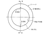
すなわち、図5において符号1で示されるものは、輪状鉄心2からなるロータであり、このロータ1の外側形状は、図示しないスロット内に励磁巻線とn相の出力巻線を有する輪状ステータとの間のギャップパーミアンスが角度θに対して正弦波状に変化することができるように非真円形状で構成されている。
前記ロータ1は、その回転によって前記ギャップパーミアンスが変化する周知のバリアブルリラクタンス型角度検出器を構成するために用いられており、このロータ1の内孔1Aの内径を形成する内径壁1Aaには複数の凹部3が形成されている。
【0003】
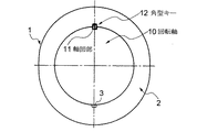
前記ロータ1の内孔1A内には、図7及び図8で示される相手側の回転軸10が嵌合されており、この回転軸10の外周には、前記各凹部3に対応して軸凹部11が形成されている。
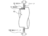
前記軸凹部11内に設けられた角型キー12は、前記ロータ1の凹部3内に嵌合していることにより、回転軸10とロータ1とは一体状に構成されている。
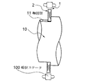
なお、前述のロータ1に対峙するステータは、図8に仮想線の符号100にて示される通りである。
【0004】
【発明が解決しようとする課題】
従来のバリアブルリラクタンス型角度検出器用ロータ構造は、以上のように構成されていたため、次のような課題が存在していた。
すなわち、ロータの内径壁に形成した凹部と回転軸の外周面に形成した軸凹部とを角型キーによって結合しなければならず、ロータを薄型とした場合(特に、近年は小型化及び薄型化の傾向にある)、この凹部の強度が低下し、薄型化への大きい障害となっていた。
【0005】
本発明は、以上のような課題を解決するためになされたもので、特に、輪状鉄心からなるロータの内径壁に突起を設け、固定用キーを用いることなく回転軸に固定することにより、ロータと回転軸との結合強度を向上させると共にコストダウンを達成するようにしたバリアブルリラクタンス型角度検出器用ロータ構造を提供することを目的とする。
【0006】
【課題を解決するための手段】
本発明によるバリアブルリラクタンス型角度検出器用ロータ構造は、輪状ステータのスロット内に励磁巻線とn相の出力巻線を設け、前記輪状ステータに対して回転自在に設けられ、前記輪状ステータとの間のギャップパーミアンスが角度θに対して正弦波状に変化する形状を有すると共に輪状鉄心のみで巻線を有しない構成のロータを用い、前記ロータの内孔の内径を形成する内径壁に形成され軸心側へ突出する突起を有する構成からなるバリアブルリラクタンス型角度検出器用ロータ構造において、前記突起は、前記突起が係合するキー溝としての軸凹部を有する回転軸の円周に沿って1個又は複数個形成され、前記突起の両側には、前記内径壁に連続して形成された逃げ用凹部が設けられ、前記内孔内に前記回転軸を嵌合させた場合、前記回転軸の外周面より外側に前記各逃げ用凹部が位置し、前記軸凹部の両側に形成された角部及び前記各角部に残っているバリが前記各逃げ用凹部内に逃げて位置する構成である。
【0007】
【発明の実施の形態】
以下、図面と共に本発明によるバリアブルリラクタンス型角度検出器用ロータ構造の好適な実施の形態について説明する。なお、従来例と同一又は同等部分には同一符号を用いて説明する。
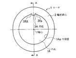
すなわち、図1において符号1で示されるものは、輪状鉄心2からなるロータであり、このロータ1の外側形状は、図示しないスロット内に励磁巻線とn相の出力巻線を有する輪状ステータとの間のギャップパーミアンスが角度θに対して正弦波状に変化することができるように非真円形状で構成されている。
【0008】
前記ロータ1は、その回転によって前記ギャップパーミアンスが変化する周知のバリアブルリラクタンス型角度検出器を構成するために用いられており、このロータ1の内孔1Aの内径を形成する内径壁1Aaには1個もしくは複数の突起3Aが軸心P側へ突出して形成されている。
【0009】
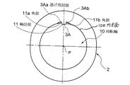
前記ロータ1の内孔1A内には、図3及び図4で示される相手側の回転軸10が嵌合されており、この回転軸10の外周には、前記各凹部3に対応してキー溝としての軸凹部11が形成されている。
前記内孔1A内に回転軸10を嵌合させた場合には、図3で示されるように、前記突起3Aと軸凹部11とが嵌合すると共に、前記軸凹部11の両側に形成された各角部11a、11bが入り込んで逃げることができるように、前記突起3Aの両側に逃げ用凹部3Aa、3Abが形成されている。尚、前記各逃げ用凹部3Aa,3Abは、前記回転軸10の外周面10aより外側に位置している。
【0010】
前記各逃げ用凹部3Aa、3Abは、前記内径壁1Aaよりもわずかに外側へ喰い込んだ形状(すなわち、従来用いられていた前記凹部3の深さに比べれば全く無視できる程度の深さである)で構成されている。
従って、前記回転軸10に前記軸凹部11を切削加工等によって形成した場合に、この軸凹部11の両側の各角部11a、11bにバリ等が残っている場合でも、このバリ等は前記各逃げ用凹部3Aa、3Ab内に逃げて位置することができ、前記突起3Aと軸凹部11との嵌合が容易かつ確実となるように構成されている。
なお、通常、ロータ1は積層型と焼結による一体型とが用いられ、積層型の場合には、この凹部3の数と転積(周知のように積層時の円周方向における磁気的特性を均一化するために1枚毎の積層片を所定角度(周知の軸倍角による)ずつ回転させる構成)とを連動させている。
また、前記突起3Aを1ケ所とした場合には、転積を行うことはないが、例えば、軸倍角が2倍角(2X)の場合(ロータ外径が2ケ所凸状となっている)は2ケ所の突起3Aを用いて180°毎各積層片を回転させて転積を行い、軸倍角が3倍角(3X)の場合(ロータ外径が3ケ所凸状となっている)は3ケ所の突起3Aを用いて120°毎各積層片を回転させて転積を行い、軸倍角が4倍角(4X)の場合(ロータ外径が4ケ所凸状となっている)は4ケ所の突起3Aを用いて90°毎各積層片を回転させて転積を行うように構成することもできる。
【0011】
【発明の効果】
本発明によるバリアブルリラクタンス型角度検出器用ロータ構造は、以上のように構成されているため、次のような効果を得ることができる。
すなわち、ロータの内径壁に形成された突起を回転軸の外周面の凹部に嵌合させることにより、ロータと回転軸との位置決め接続を達成しているため、従来の角型キーを必要とせず、構成が簡略化できる。
また、ロータには突起を設けているだけであるため、ロータの肉厚が薄肉化した場合でも、十分な強度を保つことができ、より薄肉化したレゾルバ等を得ることができる。
【図面の簡単な説明】
【図1】 本発明によるバリアブルリラクタンス型角度検出器用ロータ構造を示す正面図である。
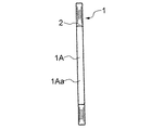
【図2】 図1のA−A線による断面図である。
【図3】 図1のロータに回転軸を嵌合した状態を示す正面図である。
【図4】 図3の一部断面付き側面図である。
【図5】 従来のバリアブルリラクタンス型角度検出器用ロータ構造を示す正面図である。
【図6】 図5のB−B断面図である。
【図7】 図5のロータに回転軸を嵌合した状態を示す一部断面付き正面図である。
【図8】 図7の一部断面付き側面図である。
【符号の説明】
1 ロータ
2 輪状鉄心
1A 内孔
1Aa 内径壁
3A 突起
3Aa、3Ab 逃げ用凹部
P 軸心
10 回転軸
10a 外周面
11 軸凹部
11a、11b 逃げ用凹部[0001]
BACKGROUND OF THE INVENTION
The present invention relates to a rotor structure for a variable reluctance type angle detector, and in particular, by providing a protrusion on the inner diameter wall of a rotor made of a ring-shaped iron core and fixing the rotor to the rotary shaft without using a fixing key. The present invention relates to a novel improvement for improving the bond strength and reducing the cost.
[0002]
[Prior art]
Conventionally, as this type of rotor structure for a variable reluctance type angle detector, the configuration shown in FIGS. 5 to 8 has been generally adopted.
That is, what is indicated by reference numeral 1 in FIG. 5 is a rotor composed of a ring-
The rotor 1 is used to construct a known variable reluctance type angle detector in which the gap permeance is changed by its rotation, and a plurality of inner diameter walls 1Aa forming the inner diameter of the
[0003]
A mating
Since the
The stator facing the rotor 1 is as indicated by the
[0004]
[Problems to be solved by the invention]
Since the conventional rotor structure for a variable reluctance type angle detector is configured as described above, the following problems exist.
That is, the concave portion formed on the inner diameter wall of the rotor and the shaft concave portion formed on the outer peripheral surface of the rotating shaft must be coupled by a square key. ), The strength of the concave portion was lowered, which was a great obstacle to thinning.
[0005]
The present invention has been made to solve the above-described problems, and in particular, by providing a protrusion on the inner diameter wall of a rotor made of a ring-shaped iron core and fixing the rotor to a rotating shaft without using a fixing key, the rotor It is an object of the present invention to provide a rotor structure for a variable reluctance type angle detector that improves the coupling strength between the rotating shaft and the rotating shaft and achieves cost reduction.
[0006]
[Means for Solving the Problems]
A rotor structure for a variable reluctance type angle detector according to the present invention is provided with an excitation winding and an n-phase output winding in a slot of a ring-shaped stator, and is provided rotatably with respect to the ring-shaped stator. axis are formed on the inner diameter wall have use a rotor structure without winding only annular core to form an inner diameter of the inner hole of said rotor and having a shape that varies sinusoidally with respect to the gap permeance angle θ of in variable reluctance-type angle detector rotor structure comprising a configuration having a projection which projects center side, the projection is one wherein the projections along a circumference of the rotary shaft having an axis recess as keyway engaging or is a plurality formed, wherein on both sides of the protrusions, the continuous to the inner diameter wall formed relief recesses provided, if the rotary shaft is fitted into said hole, The escape recesses are located outside the outer peripheral surface of the rotary shaft, and the corners formed on both sides of the shaft recess and the burrs remaining at the corners escape into the escape recesses. a configuration that.
[0007]
DETAILED DESCRIPTION OF THE INVENTION
DESCRIPTION OF EMBODIMENTS Hereinafter, preferred embodiments of a rotor structure for a variable reluctance type angle detector according to the present invention will be described with reference to the drawings. Note that the same reference numerals are used for the same or equivalent parts as in the conventional example.
That is, what is indicated by reference numeral 1 in FIG. 1 is a rotor composed of a ring-
[0008]
The rotor 1 is used to construct a known variable reluctance type angle detector in which the gap permeance is changed by its rotation, and the inner diameter wall 1Aa forming the inner diameter of the
[0009]
A mating
When the
[0010]
Each of the escape recesses 3Aa and 3Ab has a shape slightly biting outward from the inner diameter wall 1Aa (that is, a depth that can be completely ignored compared to the depth of the
Therefore, when the shaft recess 11 is formed on the
Normally, the rotor 1 is a laminated type or an integrated type by sintering. In the case of the laminated type, the number of the
Further, when the projection 3A is provided at one place, no transposition is performed. However, for example, when the shaft double angle is a double angle (2X) (the rotor outer diameter is convex at two places). When each laminated piece is rotated by 180 ° using two protrusions 3A and rolled, the product is rolled, and when the shaft double angle is triple (3X) (the rotor outer diameter is convex at three points), three points are obtained. When each laminated piece is rotated every 120 ° using the projections 3A, rolling is performed, and when the shaft double angle is 4 × (4X) (the rotor outer diameter is convex at 4 points), 4 protrusions It is also possible to perform the transposition by rotating each laminated piece every 90 ° using 3A.
[0011]
【The invention's effect】
Since the rotor structure for a variable reluctance type angle detector according to the present invention is configured as described above, the following effects can be obtained.
That is, the projection formed on the inner diameter wall of the rotor is fitted into the recess on the outer peripheral surface of the rotating shaft, thereby achieving the positioning connection between the rotor and the rotating shaft, so that a conventional square key is not required. The configuration can be simplified.
Further, since only the protrusion is provided on the rotor, sufficient strength can be maintained even when the thickness of the rotor is reduced, and a thinner resolver or the like can be obtained.
[Brief description of the drawings]
FIG. 1 is a front view showing a rotor structure for a variable reluctance angle detector according to the present invention.
FIG. 2 is a cross-sectional view taken along line AA in FIG.
3 is a front view showing a state in which a rotating shaft is fitted to the rotor of FIG. 1; FIG.
4 is a side view with a partial cross section of FIG. 3. FIG.
FIG. 5 is a front view showing a conventional rotor structure for a variable reluctance type angle detector.
6 is a cross-sectional view taken along the line BB in FIG.
7 is a front view with a partial cross section showing a state in which a rotating shaft is fitted to the rotor of FIG. 5. FIG.
FIG. 8 is a side view with a partial cross section of FIG. 7;
[Explanation of symbols]
DESCRIPTION OF SYMBOLS 1
10a outer
Claims (1)
前記突起(3A)は、前記突起(3A)が係合するキー溝としての軸凹部(11)を有する回転軸(10)の円周に沿って1個又は複数個形成され、
前記突起(3A)の両側には、前記内径壁(1Aa)に連続して形成された逃げ用凹部(3Aa,3Ab)が設けられ、前記内孔(1A)内に前記回転軸(10)を嵌合させた場合、前記回転軸(10)の外周面(10a)より外側に前記各逃げ用凹部(3Aa,3Ab)が位置し、前記軸凹部(11)の両側に形成された角部(11a,11b)及び前記各角部(11a,11b)に残っているバリが前記各逃げ用凹部(3Aa,3Ab)内に逃げて位置することを特徴とするバリアブルリラクタンス型角度検出器。An excitation winding and an n-phase output winding are provided in the slot of the annular stator (100), and are provided rotatably with respect to the annular stator (100). The gap permeance with the annular stator is at an angle θ. an inner diameter which forms an inner diameter of have use the rotor (1) configuration of having no winding only annular iron core (2) which has a shape that varies sinusoidally, the inner bore of the rotor (1) (1A) for in variable reluctance-type angle detector rotor structure comprising a structure that having a projection (3A) which projects the wall is formed (1Aa) axis (P) side,
One or a plurality of the protrusions (3A) are formed along the circumference of the rotating shaft (10) having a shaft recess (11) as a key groove with which the protrusion (3A) is engaged ,
On both sides of the projection (3A), relief recesses (3Aa, 3Ab) formed continuously on the inner diameter wall ( 1Aa) are provided , and the rotating shaft (10) is placed in the inner hole (1A). When fitted, the escape recesses (3Aa, 3Ab) are positioned outside the outer peripheral surface (10a) of the rotary shaft (10), and corner portions formed on both sides of the shaft recess (11) ( 11a, 11b) and the corners (11a, 11b) in the remaining burr each relief recess (3Aa, 3Ab) in the escape characteristics and to Luba rear Bull reluctance angle detector and a position child vessel.
Priority Applications (1)
| Application Number | Priority Date | Filing Date | Title |
|---|---|---|---|
| JP2000374590A JP4635124B2 (en) | 2000-12-08 | 2000-12-08 | Rotor structure for variable reluctance type angle detector |
Applications Claiming Priority (1)
| Application Number | Priority Date | Filing Date | Title |
|---|---|---|---|
| JP2000374590A JP4635124B2 (en) | 2000-12-08 | 2000-12-08 | Rotor structure for variable reluctance type angle detector |
Publications (2)
| Publication Number | Publication Date |
|---|---|
| JP2002174535A JP2002174535A (en) | 2002-06-21 |
| JP4635124B2 true JP4635124B2 (en) | 2011-02-16 |
Family
ID=18843749
Family Applications (1)
| Application Number | Title | Priority Date | Filing Date |
|---|---|---|---|
| JP2000374590A Expired - Fee Related JP4635124B2 (en) | 2000-12-08 | 2000-12-08 | Rotor structure for variable reluctance type angle detector |
Country Status (1)
| Country | Link |
|---|---|
| JP (1) | JP4635124B2 (en) |
Cited By (1)
| Publication number | Priority date | Publication date | Assignee | Title |
|---|---|---|---|---|
| CN108631533A (en) * | 2017-03-17 | 2018-10-09 | 美蓓亚三美株式会社 | rotor and rotary transformer |
Families Citing this family (13)
| Publication number | Priority date | Publication date | Assignee | Title |
|---|---|---|---|---|
| JP4070674B2 (en) * | 2003-07-31 | 2008-04-02 | 株式会社東芝 | Reluctance rotor |
| JP2008187804A (en) | 2007-01-29 | 2008-08-14 | Toyota Motor Corp | Rotor and rotating electric machine equipped with the rotor |
| JP5012169B2 (en) * | 2007-04-23 | 2012-08-29 | 日本電産株式会社 | Resolver |
| JP5262583B2 (en) * | 2008-10-30 | 2013-08-14 | トヨタ自動車株式会社 | Resolver integrated rotary electric machine and rotor core |
| JP5567775B2 (en) * | 2008-11-14 | 2014-08-06 | トヨタ自動車株式会社 | Rotor and rotating electric machine |
| JP5162536B2 (en) * | 2009-08-04 | 2013-03-13 | 日立オートモティブシステムズ株式会社 | Rotor core and rotating electric machine |
| JP5490559B2 (en) * | 2010-02-16 | 2014-05-14 | 日立オートモティブシステムズ株式会社 | Rotor and rotating electric machine using the rotor |
| EP2666696A4 (en) * | 2011-01-20 | 2017-12-27 | Nippon Steel & Sumitomo Metal Corporation | Vehicle body height adjustment valve having resolver for railway carriage |
| JP2012254747A (en) * | 2011-06-10 | 2012-12-27 | Toyota Motor Corp | Rear wheel steering device |
| JP6136477B2 (en) * | 2013-04-02 | 2017-05-31 | 株式会社ジェイテクト | Rotating electric machine and manufacturing method thereof |
| JP6381745B1 (en) * | 2017-06-16 | 2018-08-29 | 三菱電機株式会社 | Rotation angle detection device and vehicle drive motor provided with rotation angle detection device |
| JP6674931B2 (en) * | 2017-08-10 | 2020-04-01 | ミネベアミツミ株式会社 | Resolver and motor |
| JP2024053322A (en) * | 2022-10-03 | 2024-04-15 | ミネベアミツミ株式会社 | Resolver rotor and resolver |
Family Cites Families (2)
| Publication number | Priority date | Publication date | Assignee | Title |
|---|---|---|---|---|
| JPH08308196A (en) * | 1995-05-02 | 1996-11-22 | Otsupama Kogyo Kk | Magnet generator rotor |
| JPH0932813A (en) * | 1995-07-20 | 1997-02-04 | Kobe Steel Ltd | Power transmission groove in rotary body |
-
2000
- 2000-12-08 JP JP2000374590A patent/JP4635124B2/en not_active Expired - Fee Related
Cited By (3)
| Publication number | Priority date | Publication date | Assignee | Title |
|---|---|---|---|---|
| CN108631533A (en) * | 2017-03-17 | 2018-10-09 | 美蓓亚三美株式会社 | rotor and rotary transformer |
| US10971980B2 (en) | 2017-03-17 | 2021-04-06 | Minebea Mitsumi Inc. | Rotor and resolver |
| CN108631533B (en) * | 2017-03-17 | 2022-03-01 | 美蓓亚三美株式会社 | Rotor and rotary transformer |
Also Published As
| Publication number | Publication date |
|---|---|
| JP2002174535A (en) | 2002-06-21 |
Similar Documents
| Publication | Publication Date | Title |
|---|---|---|
| JP4635124B2 (en) | Rotor structure for variable reluctance type angle detector | |
| JP5565365B2 (en) | Rotor for rotating electrical machine and method for manufacturing the same | |
| KR100274113B1 (en) | Stator of motor | |
| JP2000270503A (en) | Permanent magnet motor | |
| JP2005033941A (en) | Permanent magnet motor stator core and permanent magnet motor | |
| US4881002A (en) | Miniature motor | |
| JP5067365B2 (en) | motor | |
| JP2000050540A (en) | Assembling teeth type stator core of rotating electric machine | |
| JPH0686524A (en) | Brushless motor | |
| JP4244111B2 (en) | Permanent magnet synchronous motor rotor | |
| JP2002315237A (en) | Laminated core of rotating electric machine | |
| JP3821185B2 (en) | Permanent magnet motor | |
| JPH09233744A (en) | Synchronous motor | |
| JP2005051826A (en) | Permanent magnet fixing structure in rotor of rotating electrical machine | |
| JP7718258B2 (en) | Rotor and rotating electric machine | |
| JPH08116632A (en) | Rotating electric machine stator | |
| JP2003333812A (en) | Induction motor rotor | |
| JP2741937B2 (en) | Cage type rotor | |
| KR20010061839A (en) | An assembly structure of a rotor for servo motor | |
| JP2002010539A (en) | Armature | |
| JPH09261932A (en) | Electric motor | |
| JP2001218392A (en) | Brushless dc motor | |
| JPH0638412A (en) | Permanent magnet type brushless rotating electric machine | |
| JPH0516853Y2 (en) | ||
| JP6853335B2 (en) | Stator and rotary machine |
Legal Events
| Date | Code | Title | Description |
|---|---|---|---|
| RD04 | Notification of resignation of power of attorney |
Free format text: JAPANESE INTERMEDIATE CODE: A7424 Effective date: 20060615 |
|
| A621 | Written request for application examination |
Free format text: JAPANESE INTERMEDIATE CODE: A621 Effective date: 20070703 |
|
| RD04 | Notification of resignation of power of attorney |
Free format text: JAPANESE INTERMEDIATE CODE: A7424 Effective date: 20070717 |
|
| A131 | Notification of reasons for refusal |
Free format text: JAPANESE INTERMEDIATE CODE: A131 Effective date: 20100406 |
|
| A521 | Request for written amendment filed |
Free format text: JAPANESE INTERMEDIATE CODE: A523 Effective date: 20100531 |
|
| TRDD | Decision of grant or rejection written | ||
| A01 | Written decision to grant a patent or to grant a registration (utility model) |
Free format text: JAPANESE INTERMEDIATE CODE: A01 Effective date: 20100907 |
|
| A01 | Written decision to grant a patent or to grant a registration (utility model) |
Free format text: JAPANESE INTERMEDIATE CODE: A01 |
|
| A61 | First payment of annual fees (during grant procedure) |
Free format text: JAPANESE INTERMEDIATE CODE: A61 Effective date: 20100910 |
|
| FPAY | Renewal fee payment (event date is renewal date of database) |
Free format text: PAYMENT UNTIL: 20131203 Year of fee payment: 3 |
|
| R150 | Certificate of patent or registration of utility model |
Ref document number: 4635124 Country of ref document: JP Free format text: JAPANESE INTERMEDIATE CODE: R150 Free format text: JAPANESE INTERMEDIATE CODE: R150 |
|
| R250 | Receipt of annual fees |
Free format text: JAPANESE INTERMEDIATE CODE: R250 |
|
| R250 | Receipt of annual fees |
Free format text: JAPANESE INTERMEDIATE CODE: R250 |
|
| R250 | Receipt of annual fees |
Free format text: JAPANESE INTERMEDIATE CODE: R250 |
|
| R250 | Receipt of annual fees |
Free format text: JAPANESE INTERMEDIATE CODE: R250 |
|
| R250 | Receipt of annual fees |
Free format text: JAPANESE INTERMEDIATE CODE: R250 |
|
| R250 | Receipt of annual fees |
Free format text: JAPANESE INTERMEDIATE CODE: R250 |
|
| R250 | Receipt of annual fees |
Free format text: JAPANESE INTERMEDIATE CODE: R250 |
|
| LAPS | Cancellation because of no payment of annual fees |