JP2005033941A - Stator core for permanent magnet motor, and permanent magnet motor - Google Patents
Stator core for permanent magnet motor, and permanent magnet motor Download PDFInfo
- Publication number
- JP2005033941A JP2005033941A JP2003271872A JP2003271872A JP2005033941A JP 2005033941 A JP2005033941 A JP 2005033941A JP 2003271872 A JP2003271872 A JP 2003271872A JP 2003271872 A JP2003271872 A JP 2003271872A JP 2005033941 A JP2005033941 A JP 2005033941A
- Authority
- JP
- Japan
- Prior art keywords
- permanent magnet
- rotor
- center
- gap length
- ratio
- Prior art date
- Legal status (The legal status is an assumption and is not a legal conclusion. Google has not performed a legal analysis and makes no representation as to the accuracy of the status listed.)
- Pending
Links
Images


Classifications
-
- H—ELECTRICITY
- H02—GENERATION; CONVERSION OR DISTRIBUTION OF ELECTRIC POWER
- H02K—DYNAMO-ELECTRIC MACHINES
- H02K1/00—Details of the magnetic circuit
- H02K1/06—Details of the magnetic circuit characterised by the shape, form or construction
- H02K1/12—Stationary parts of the magnetic circuit
- H02K1/14—Stator cores with salient poles
- H02K1/146—Stator cores with salient poles consisting of a generally annular yoke with salient poles
-
- H—ELECTRICITY
- H02—GENERATION; CONVERSION OR DISTRIBUTION OF ELECTRIC POWER
- H02K—DYNAMO-ELECTRIC MACHINES
- H02K1/00—Details of the magnetic circuit
- H02K1/06—Details of the magnetic circuit characterised by the shape, form or construction
- H02K1/12—Stationary parts of the magnetic circuit
- H02K1/16—Stator cores with slots for windings
-
- H—ELECTRICITY
- H02—GENERATION; CONVERSION OR DISTRIBUTION OF ELECTRIC POWER
- H02K—DYNAMO-ELECTRIC MACHINES
- H02K1/00—Details of the magnetic circuit
- H02K1/06—Details of the magnetic circuit characterised by the shape, form or construction
- H02K1/22—Rotating parts of the magnetic circuit
- H02K1/27—Rotor cores with permanent magnets
- H02K1/2706—Inner rotors
- H02K1/272—Inner rotors the magnetisation axis of the magnets being perpendicular to the rotor axis
- H02K1/274—Inner rotors the magnetisation axis of the magnets being perpendicular to the rotor axis the rotor consisting of two or more circumferentially positioned magnets
- H02K1/2753—Inner rotors the magnetisation axis of the magnets being perpendicular to the rotor axis the rotor consisting of two or more circumferentially positioned magnets the rotor consisting of magnets or groups of magnets arranged with alternating polarity
-
- H—ELECTRICITY
- H02—GENERATION; CONVERSION OR DISTRIBUTION OF ELECTRIC POWER
- H02K—DYNAMO-ELECTRIC MACHINES
- H02K15/00—Methods or apparatus specially adapted for manufacturing, assembling, maintaining or repairing of dynamo-electric machines
- H02K15/02—Methods or apparatus specially adapted for manufacturing, assembling, maintaining or repairing of dynamo-electric machines of stator or rotor bodies
- H02K15/03—Methods or apparatus specially adapted for manufacturing, assembling, maintaining or repairing of dynamo-electric machines of stator or rotor bodies having permanent magnets
-
- H—ELECTRICITY
- H02—GENERATION; CONVERSION OR DISTRIBUTION OF ELECTRIC POWER
- H02K—DYNAMO-ELECTRIC MACHINES
- H02K3/00—Details of windings
- H02K3/46—Fastening of windings on the stator or rotor structure
- H02K3/48—Fastening of windings on the stator or rotor structure in slots
Abstract
Description
本発明は、複数個のティースを回転軸に対して放射状に配置して回転時に発生する誘起電圧を低下させること無くコギングトルクの低減化を図るようにした永久磁石形モータの固定子鉄心及び永久磁石形モータに関する。 The present invention relates to a stator core and a permanent magnet of a permanent magnet type motor in which a plurality of teeth are arranged radially with respect to a rotating shaft so as to reduce cogging torque without reducing induced voltage generated during rotation. The present invention relates to a magnet type motor.
永久磁石形モータの固定子鉄心について、回転時に発生する誘起電圧を低下させること無くコギングトルクの低減化を図ることを目的とした従来技術として、例えば特許文献1に開示されているものがある。
この技術は、外転型のモータにおいて、ティースヘッドの回転子永久磁石と対向する側の面の形状を、周方向の中央部については回転子の回転中心を中心とする円弧状に形成し、その周方向中央部から周方向の両端部に向かうに従って滑らかに回転子永久磁石から遠ざかる形状としたものである。
In the outer rotation type motor, this technology forms the shape of the surface on the side facing the rotor permanent magnet of the teeth head in an arc shape centering on the rotation center of the rotor at the center in the circumferential direction. The shape is such that it smoothly moves away from the rotor permanent magnet from the circumferential center to both ends in the circumferential direction.
ところで、ティースヘッドの面形状を上記のように形成する場合、ティースヘッドの両端部が回転子永久磁石に近付くように、即ち両者間の空隙が小さくなるようにすれば、回転子に対して作用する有効磁束量は多くなり発生する誘起電圧は大きくなるが、その一方でコギングトルク及びトルクリップルも大きくなる。また、ティースヘッドの両端部が回転子永久磁石から遠ざかるように、即ち両者間の空隙が大きくなるようにすれば、コギングトルク及びトルクリップルは小さくなるが有効磁束量も小さくなるため、発生する誘起電圧も小さくなる。 By the way, when the surface shape of the teeth head is formed as described above, if both ends of the teeth head come close to the rotor permanent magnet, that is, if the gap between the two is reduced, the teeth head acts on the rotor. The effective magnetic flux to be generated increases and the generated induced voltage increases, while the cogging torque and torque ripple also increase. In addition, if both ends of the teeth head are moved away from the rotor permanent magnet, that is, the gap between the two is increased, the cogging torque and the torque ripple are reduced but the effective magnetic flux is also reduced. The voltage is also reduced.
即ち、ティースヘッドの両端部と回転子永久磁石との空隙長をどのように設定するかについては、誘起電圧レベルの確保とコギングトルク及びトルクリップルの抑制との間にトレードオフとなる関係がある。従って、前記空隙長については、両者の関係が最適となるように設定すべきであるが、特許文献1にはその開示が無い。
本発明は上記事情に鑑みてなされたものであり、その目的は、回転時に発生する誘起電圧を低下させること無くコギングトルクの低減化をより効果的に図ることができる永久磁石形モータの固定子鉄心及び永久磁石形モータを提供することにある。
That is, there is a trade-off relationship between securing the induced voltage level and suppressing cogging torque and torque ripple as to how to set the gap length between the both ends of the teeth head and the rotor permanent magnet. . Accordingly, the gap length should be set so that the relationship between the two is optimum, but
The present invention has been made in view of the above circumstances, and a purpose thereof is a stator of a permanent magnet type motor that can more effectively reduce cogging torque without lowering an induced voltage generated during rotation. An object is to provide an iron core and a permanent magnet type motor.
請求項1記載の永久磁石形モータの固定子鉄心は、複数個のティースを回転軸に対して放射状に配置し、
前記ティースの先端部におけるティースヘッドの回転子永久磁石と対向する側の面形状を前記永久磁石側に凸とすると共に、
前記ティースヘッドと回転子永久磁石との空隙長を、周方向の中央に対する両端の比率が1.4〜2.4の範囲となるように設定する。
The stator core of the permanent magnet type motor according to
The surface shape of the teeth head on the side facing the rotor permanent magnet of the tooth head is convex to the permanent magnet side, and
The gap length between the tooth head and the rotor permanent magnet is set so that the ratio of both ends with respect to the center in the circumferential direction is in the range of 1.4 to 2.4.
即ち、本発明の発明者等は、前記空隙長の比率を変化させた場合に、誘起電圧とコギングトルクとの発生状態をシミュレーションした。その結果、周方向の中央に対する両端の比率を1.4〜2.4の範囲に設定すると、両者のバランスが程良い状態になることを明らかにした。
また、請求項2に記載したように、ティースヘッドの回転子永久磁石と対向する側の面形状を前記永久磁石側に凸とすると共に、空隙長の比率を1.6〜2.2の範囲に設定し、更に、請求項3に記載したように、空隙長の比率を1.8〜2.0の範囲に設定すれば、誘起電圧とコギングトルクとの発生バランスがより最適となることが判った。
That is, the inventors of the present invention simulated the generation state of the induced voltage and the cogging torque when the ratio of the gap length was changed. As a result, it has been clarified that when the ratio of both ends with respect to the center in the circumferential direction is set in the range of 1.4 to 2.4, the balance between the two becomes moderate.
In addition, as described in
請求項4記載の永久磁石形モータの固定子鉄心は、複数個のティースを回転軸に対して放射状に配置してなり、
前記ティースの先端部におけるティースヘッドの回転子永久磁石と対向する側の面形状は、周方向の中央部が回転子の回転中心を中心とする円弧状で且つ両端部が前記円弧の両端に夫々接する接線を成すように形成すると共に、
前記ティースヘッドと回転子永久磁石との空隙長は、周方向の中央に対する両端の比率が1.6〜2.6の範囲となるように設定する。
The stator core of the permanent magnet type motor according to claim 4, wherein a plurality of teeth are arranged radially with respect to the rotation axis,
The surface shape of the teeth head on the side facing the rotor permanent magnet of the teeth head has an arc shape with the center in the circumferential direction centering on the rotation center of the rotor and both ends at the ends of the arc. While forming to make a tangent that touches,
The gap length between the tooth head and the rotor permanent magnet is set so that the ratio of both ends with respect to the center in the circumferential direction is in the range of 1.6 to 2.6.
即ち、ティースヘッドの面形状において、円弧状をなす中央部に連なる両端部を、前記円弧の両端に夫々接する接線を成すように形成すると、中央部から両端部にかけての空隙長の変化がより緩やかになるので、空隙長を調整するのにより有利となる。
そして、この場合も、請求項5に記載したように、空隙長の比率を1.8〜2.4の範囲に設定し、更に、請求項6に記載したように、前記空隙長の比率を2.0〜2.2の範囲に設定すれば、誘起電圧とコギングトルクとの発生バランスがより最適となる。
In other words, in the surface shape of the teeth head, when both end portions connected to the arc-shaped central portion are formed so as to form tangent lines respectively contacting both ends of the arc, the change in the gap length from the central portion to both end portions is more gradual. Therefore, it is more advantageous to adjust the gap length.
And also in this case, as described in
請求項1記載の永久磁石形モータの固定子鉄心によれば、複数個のティースを回転軸に対して放射状に配置し、ティースヘッドの回転子永久磁石と対向する側の面形状を永久磁石側に凸とすると共に、ティースヘッドと回転子永久磁石との空隙長を、周方向の中央に対する両端の比率が1.4〜2.4の範囲となるように設定した。従って、前記固定子鉄心を備えて構成されるモータが回転する場合における誘起電圧とコギングトルクとの発生状態のバランスを最適化することができ、モータの効率低下を極力防止した上で、振動や騒音の発生を抑制することが可能となる。
According to the stator core of the permanent magnet type motor according to
請求項4記載の永久磁石形モータの固定子鉄心によれば、複数個のティースを回転軸に対して放射状に配置し、ティースヘッドの回転子永久磁石と対向する側の面形状を、周方向の中央部が回転子の回転中心を中心とする円弧状で且つ両端部が円弧の両端に夫々接する接線を成すように形成し、ティースヘッドと回転子永久磁石との空隙長を、周方向の中央に対する両端の比率が1.6〜2.6の範囲となるように設定した。従って、請求項1と同様の効果が得られると共に、中央部から両端部にかけての空隙長の変化がより緩やかになり、空隙長の調整をより容易に行なうことができる。 According to the stator core of the permanent magnet type motor according to claim 4, a plurality of teeth are arranged radially with respect to the rotating shaft, and the surface shape of the teeth head facing the rotor permanent magnet is set in the circumferential direction. The center portion of the rotor is formed in an arc shape centering on the rotation center of the rotor and both end portions form tangents that are in contact with both ends of the arc, respectively, and the gap length between the teeth head and the rotor permanent magnet is set in the circumferential direction. The ratio of both ends to the center was set to be in the range of 1.6 to 2.6. Therefore, the same effect as that of the first aspect can be obtained, and the change of the gap length from the central portion to the both end portions becomes more gradual, and the gap length can be adjusted more easily.
(第1実施例)
以下、本発明を外転形の永久磁石形モータに適用した場合の第1実施例について図1乃至図4を参照して説明する。まず、図4には、外転形の永久磁石形モータ1の縦断面図が示されている。この図4において、固定子鉄心2は、ケイ素鋼板を打ち抜いたリング状のものを多数枚積層して構成されたもので、これの中央部には軸受3を装着するための円形の孔4が形成され、外周部には、図3に示すように、この場合12個のティース5が周方向に設けられている。
(First embodiment)
A first embodiment in which the present invention is applied to an outer rotation type permanent magnet motor will be described below with reference to FIGS. First, FIG. 4 shows a longitudinal cross-sectional view of an outer rotation type
ティース5には、それぞれ電機子巻線7が巻装されており、ティース5の先端部におけるティースヘッド5aは、電機子巻線7から径方向外側へ突出している。そして、固定子鉄心2と各電機子巻線7により、固定子8が構成されている。
これに対して、回転子10は、上記軸受3に回転自在に支承された回転軸11と、この回転軸11の上端部に固着された回転子ヨーク12と、この回転子ヨーク12の筒部12aの内周面に設けられた円筒状をなす回転子永久磁石13とから構成されていて、この回転子永久磁石13が、固定子鉄心2におけるティース5のティースヘッド5aに対してエアギャップ(空隙)を介して径方向から対向するように配置されている。
An armature winding 7 is wound around each of the
On the other hand, the
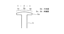
ここで、図1(a)又は図2に示すように、ティース5のティースヘッド5aにおける回転子永久磁石13と対向する側の面の形状は、中央部となる5bが、回転子10の回転中心O1を中心とする半径がr1の円弧状に形成されている。従って、ティースヘッド5aの中央部5bと回転子永久磁石13との間のエアギャップ長G1は、周方向において同じである。
Here, as shown in FIG. 1A or FIG. 2, the shape of the surface of the
そして、中央部5bの両側に連なる端部5c,5dにおける回転子永久磁石13側の面の形状は、中央部5bを成す円弧の端点に対して接線をなすように形成している。尚、これらは面形状を2次元的に表現したものであるが、3次元的に表現すれば、中央部5bの面形状は円筒面をなしているので、端部5c,5dの面形状は、その円筒面端に対して軸方向に直線で接する接平面を成していることになる。
And the shape of the surface by the side of the rotor
また、図2に示すように、端部5c,中央部5b,端部5dの周方向配置比率は略1:2:1となるように形成している。この場合、ティースヘッド5aにおける回転子永久磁石13と対向する側の面形状は、中央部5bから両端部5c,5dに夫々向かうに従って滑らかに回転子永久磁石13から遠ざかる形状となっており、ティースヘッド5aと回転子永久磁石13との間のエアギャップ長は、両端部5c,5dの夫々の端に向かうに従って次第に大きくなる。そして、端部5cの左端と端部5dの右端では回転子永久磁石13に対するエアギャップ長G2が最大となるが、エアギャップ長G1,G2の比は1:2となるように設定されている。
Further, as shown in FIG. 2, the
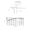
図1(b)には、横軸にエアギャップ長の比G2/G1をとり、縦軸に永久磁石モータ1の回転時に発生する誘起電圧とコギングトルクとの比を取って示すものである。即ち、前述したように、ティースヘッド5aの両端部5c,5dが回転子永久磁石13に近付けば発生する誘起電圧は大きくなるが、その一方でコギングトルク,トルクリップルも大きくなり、両端部5c,5dが回転子永久磁石13から遠ざかれば、コギングトルク,トルクリップルは小さくなるが発生する誘起電圧も小さくなる。
FIG. 1B shows the air gap length ratio G2 / G1 on the horizontal axis and the ratio of the induced voltage and cogging torque generated when the
従って、コギングトルクを極力小さく、誘起電圧を極力大きくするための指標として比(誘起電圧)/(コギングトルク)を用い、エアギャップ長の比G2/G1を変化させた場合に、(誘起電圧)/(コギングトルク)の変化をシミュレーションによって求めた。その結果、比G2/G1が略「2」となる場合に、
(誘起電圧)/(コギングトルク)は略最大を示すことが判った。
Therefore, when the ratio (induced voltage) / (cogging torque) is used as an index for making the cogging torque as small as possible and the induced voltage as large as possible, and the air gap length ratio G2 / G1 is changed, (induced voltage) The change of / (cogging torque) was obtained by simulation. As a result, when the ratio G2 / G1 is substantially “2”,
It was found that (induced voltage) / (cogging torque) was substantially maximum.
以上のように本実施例によれば、固定子鉄心2を構成するティースヘッド5aの回転子永久磁石13と対向する側の面形状を、周方向の中央部5bが回転子の回転中心を中心とする円弧状で且つ両端部5c,5dが前記円弧の両端に夫々接する接線を成すように形成し、ティースヘッド5aと回転子永久磁石13とのエアギャップ長を、周方向の中央G1に対する両端G2の比率が略「2」となるように設定した。従って、永久磁石モータ1の回転時に発生する誘起電圧を極力大きくすると共に、コギングトルク,トルクリップルを極力小さくするように両者をバランスさせることができ、モータの効率低下を極力防止した上で、振動や騒音の発生を抑制することが可能となる。
As described above, according to the present embodiment, the surface shape of the
そして、ティースヘッド5aの両端部5c,5dを、中央部5bに連なる接平面を成すように形成することで、中央部5bから両端部5c,5dにかけての空隙長の変化がより緩やかになり、空隙長を調整するのにより有利となる。
Then, by forming both
(第2実施例)
図5は本発明の第2実施例を示すものであり、第1実施例と同一部分には同一符号を付して説明を省略し、以下異なる部分についてのみ説明する。第2実施例では、ティース15のティースヘッド15aの形状が、ティースヘッド5aとは若干異なっている。
(Second embodiment)
FIG. 5 shows a second embodiment of the present invention. The same parts as those in the first embodiment are denoted by the same reference numerals and the description thereof is omitted. Only different parts will be described below. In the second embodiment, the shape of the tooth head 15a of the tooth 15 is slightly different from that of the
即ち、図5(a)に示すように、ティースヘッド15aが回転子永久磁石13と対向する側の面の形状は全て円弧、3次元的に表現すれば、回転子永久磁石13側に凸となる円筒面をなしている。この場合も第1実施例と同様に、ティースヘッド15aの面形状は、中央から両端に夫々向かうに従って滑らかに回転子永久磁石13から遠ざかる形状となっており、エアギャップ長は、両端に向かうに従って次第に大きくなる。そして、両端におけるエアギャップ長G2’は最大となるが、中央におけるエアギャップ長G1’との比は10:19となるように設定されている。
That is, as shown in FIG. 5 (a), the shape of the surface on the side where the teeth head 15a faces the rotor
図5(b)は、図1(b)相当図である。この場合も、第1実施例と同様に、その結果、比G2’/G1’が略10:19になると、(誘起電圧)/(コギングトルク)は略最大を示すことが判った。
以上のように第2実施例によれば、ティースヘッド15aが回転子永久磁石13と対向する側の面形状を回転子永久磁石13側に凸となる円筒面として、中央におけるエアギャップ長G1’と両端におけるエアギャップ長G2’との比が10:19となるように設定した。従って、第1実施例と略同様の効果が得られる。
FIG. 5B is a diagram corresponding to FIG. Also in this case, as in the first example, as a result, it was found that when the ratio G2 ′ / G1 ′ is approximately 10:19, (induced voltage) / (cogging torque) is substantially maximum.
As described above, according to the second embodiment, the surface shape of the tooth head 15a facing the rotor
(第3実施例)
図6は本発明の第3実施例を示したものである。第3実施例では、本発明を内転形の永久磁石形モータ20に適用したものである。固定子における固定子鉄心16には、内周部側に8個のティース17が設けられている。この固定子鉄心16の中心部に、回転子永久磁石18を備えた回転子19が回転可能に配設されている。そして、ティース17のティースヘッド17aにおける回転子永久磁石18と対向する側の面の形状は、それぞれ固定子鉄心16の外周方向にずれた位置を中心とする円弧状(円筒面)に形成されている。
(Third embodiment)
FIG. 6 shows a third embodiment of the present invention. In the third embodiment, the present invention is applied to an internal rotation type permanent magnet motor 20. The stator iron core 16 in the stator is provided with eight teeth 17 on the inner peripheral side. A
従って、ティース17のティースヘッド17aにおける回転子永久磁石18と対向する側の面の形状は、周方向の中央から両端に向かうに従って滑らかに回転子永久磁石18から遠ざかる形状となっており、ティース17のティースヘッド17aと回転子永久磁石18との間のエアギャップ長は、周方向の中央におけるギャップ長をG3とし、両端におけるギャップ長をG4とすると、
G4/G3=2となるように設定されている。
Therefore, the shape of the surface of the teeth 17 on the side facing the rotor permanent magnet 18 in the teeth head 17a is a shape that smoothly moves away from the rotor permanent magnet 18 toward the both ends from the center in the circumferential direction. The air gap length between the teeth head 17a and the rotor permanent magnet 18 is G3 at the circumferential center and G4 at both ends.
G4 / G3 = 2 is set.
以上のように構成された第3実施例によれば、本発明を内転形の永久磁石形モータに適用した場合も、第2施例と同様の効果が得られる。
本発明は上記し且つ図面に記載した実施例にのみ限定されるものではなく、以下のような変形または拡張が可能である。
第1実施例において、ティースヘッドと回転子永久磁石とのエアギャップ長比G2/G1は「2」とするものに限らない。例えば、エアギャップ長比を2.0〜2.2の範囲や、1.8〜2.4の範囲、或いは1.6〜2.6の範囲に設定した場合でも、有利な効果を得ることは可能である。
According to the third embodiment configured as described above, the same effects as those of the second embodiment can be obtained even when the present invention is applied to an inward-rotating permanent magnet motor.
The present invention is not limited to the embodiments described above and shown in the drawings, and the following modifications or expansions are possible.
In the first embodiment, the air gap length ratio G2 / G1 between the tooth head and the rotor permanent magnet is not limited to “2”. For example, even when the air gap length ratio is set to a range of 2.0 to 2.2, a range of 1.8 to 2.4, or a range of 1.6 to 2.6, an advantageous effect can be obtained. Is possible.
また、第2実施例において、ティースヘッドと回転子永久磁石とのエアギャップ長比G2/G1は10:19とするものに限らない。例えば、エアギャップ長比を1.8〜2.0の範囲や、1.6〜2.2の範囲、或いは1.4〜2.4の範囲に設定した場合でも、有利な効果を得ることは可能である。 In the second embodiment, the air gap length ratio G2 / G1 between the tooth head and the rotor permanent magnet is not limited to 10:19. For example, even when the air gap length ratio is set to a range of 1.8 to 2.0, a range of 1.6 to 2.2, or a range of 1.4 to 2.4, an advantageous effect can be obtained. Is possible.
図面中、1は永久磁石モータ、2は固定子鉄心、5はティース、5aはティースヘッド、5bは中央部、5c,5dは端部、13は回転子永久磁石、15はティース、15aはティースヘッド、16は固定子鉄心、17はティース、17aはティースヘッド、18は回転子永久磁石、20は永久磁石モータを示す。
In the drawings, 1 is a permanent magnet motor, 2 is a stator iron core, 5 is a tooth, 5a is a teeth head, 5b is a central portion, 5c and 5d are end portions, 13 is a rotor permanent magnet, 15 is a tooth, and 15a is a tooth. Reference numeral 16 denotes a stator iron core, 17 denotes a tooth, 17a denotes a teeth head, 18 denotes a rotor permanent magnet, and 20 denotes a permanent magnet motor.
Claims (7)
前記ティースの先端部におけるティースヘッドの回転子永久磁石と対向する側の面形状を前記永久磁石側に凸とすると共に、
前記ティースヘッドと回転子永久磁石との空隙長は、周方向の中央に対する両端の比率が1.4〜2.4の範囲となるように設定されていることを特徴とする永久磁石形モータの固定子鉄心。 A plurality of teeth are arranged radially with respect to the rotation axis,
The surface shape of the teeth head on the side facing the rotor permanent magnet of the tooth head is convex to the permanent magnet side, and
The gap length between the tooth head and the rotor permanent magnet is set so that the ratio of both ends with respect to the center in the circumferential direction is in a range of 1.4 to 2.4. Stator core.
空隙長は、周方向の中央に対する両端の比率が1.6〜2.2の範囲に設定されていることを特徴とする請求項1記載の永久磁石形モータの固定子鉄心。 While making the surface shape of the teeth head facing the rotor permanent magnet convex toward the permanent magnet side,
The stator core of the permanent magnet motor according to claim 1, wherein the gap length is set such that the ratio of both ends with respect to the center in the circumferential direction is 1.6 to 2.2.
前記ティースの先端部におけるティースヘッドの回転子永久磁石と対向する側の面形状は、周方向の中央部が回転子の回転中心を中心とする円弧状で且つ両端部が前記円弧の両端に夫々接する接線を成し、
前記ティースヘッドと回転子永久磁石との空隙長は、周方向の中央に対する両端の比率が1.6〜2.6の範囲となるように設定されていることを特徴とする永久磁石形モータの固定子鉄心。 A plurality of teeth are arranged radially with respect to the rotation axis,
The surface shape of the teeth head on the side facing the rotor permanent magnet of the teeth head has an arc shape with the center in the circumferential direction centering on the rotation center of the rotor and both ends at the ends of the arc. Make a tangent line,
The gap length between the tooth head and the rotor permanent magnet is set so that the ratio of both ends with respect to the center in the circumferential direction is in the range of 1.6 to 2.6. Stator core.
A permanent magnet type motor comprising the stator core according to any one of claims 1 to 6.
Priority Applications (2)
| Application Number | Priority Date | Filing Date | Title |
|---|---|---|---|
| JP2003271872A JP2005033941A (en) | 2003-07-08 | 2003-07-08 | Stator core for permanent magnet motor, and permanent magnet motor |
| KR1020040051862A KR100723329B1 (en) | 2003-07-08 | 2004-07-05 | A stator core of a permanent magnet motor and the permanent magnet motor |
Applications Claiming Priority (1)
| Application Number | Priority Date | Filing Date | Title |
|---|---|---|---|
| JP2003271872A JP2005033941A (en) | 2003-07-08 | 2003-07-08 | Stator core for permanent magnet motor, and permanent magnet motor |
Publications (2)
| Publication Number | Publication Date |
|---|---|
| JP2005033941A true JP2005033941A (en) | 2005-02-03 |
| JP2005033941A5 JP2005033941A5 (en) | 2006-04-27 |
Family
ID=34209597
Family Applications (1)
| Application Number | Title | Priority Date | Filing Date |
|---|---|---|---|
| JP2003271872A Pending JP2005033941A (en) | 2003-07-08 | 2003-07-08 | Stator core for permanent magnet motor, and permanent magnet motor |
Country Status (2)
| Country | Link |
|---|---|
| JP (1) | JP2005033941A (en) |
| KR (1) | KR100723329B1 (en) |
Cited By (26)
| Publication number | Priority date | Publication date | Assignee | Title |
|---|---|---|---|---|
| JP2006238667A (en) * | 2005-02-28 | 2006-09-07 | Matsushita Electric Ind Co Ltd | Electric motor |
| WO2006126552A1 (en) * | 2005-05-24 | 2006-11-30 | Denso Corporation | Motor and control device thereof |
| JP2008043071A (en) * | 2006-08-07 | 2008-02-21 | Denso Corp | Stepping motor and manufacturing method therefor |
| JP2009089547A (en) * | 2007-10-02 | 2009-04-23 | Hitachi Appliances Inc | Brushless motor |
| CN102244446A (en) * | 2010-05-11 | 2011-11-16 | 天津市松正电动科技有限公司 | Permanent magnet synchronism motor (PMSM) |
| JP2012023944A (en) * | 2010-06-15 | 2012-02-02 | Alphana Technology Co Ltd | Rotary apparatus |
| CN102594076A (en) * | 2012-03-09 | 2012-07-18 | 江门市凯斯莱工贸有限公司 | Variable-frequency three-phase brushless permanent magnet motor |
| CN104410180A (en) * | 2014-12-11 | 2015-03-11 | 东南大学 | E-shaped stator core flux switching type hybrid permanent magnet memory motor |
| CN104617720A (en) * | 2015-01-27 | 2015-05-13 | 华北电力大学(保定) | Method for weakening cogging torque of permanent magnet synchronous generator |
| CN104734446A (en) * | 2015-04-09 | 2015-06-24 | 莱克电气股份有限公司 | Built-in type permanent magnet synchronous motor |
| WO2017011682A1 (en) * | 2015-07-16 | 2017-01-19 | Bergstrom, Inc. | Combination structure between stator and rotor in a brushless motor |
| CN106712346A (en) * | 2016-12-15 | 2017-05-24 | 广东威灵电机制造有限公司 | Motor and water pump provided with same |
| US10205363B2 (en) | 2015-07-16 | 2019-02-12 | Bergstrom, Inc. | Locating structure between printed circuit board and insulating bobbin in a brushless motor |
| US10218239B2 (en) | 2015-07-16 | 2019-02-26 | Bergstrom, Inc. | Brushless motor having terminal fixing blocks |
| US10263488B2 (en) | 2015-07-16 | 2019-04-16 | Bergstrom, Inc. | Stator with insulating bobbin in a brushless motor |
| US10527332B2 (en) | 2016-01-13 | 2020-01-07 | Bergstrom, Inc. | Refrigeration system with superheating, sub-cooling and refrigerant charge level control |
| US10562372B2 (en) | 2016-09-02 | 2020-02-18 | Bergstrom, Inc. | Systems and methods for starting-up a vehicular air-conditioning system |
| US10589598B2 (en) | 2016-03-09 | 2020-03-17 | Bergstrom, Inc. | Integrated condenser and compressor system |
| US10675948B2 (en) | 2016-09-29 | 2020-06-09 | Bergstrom, Inc. | Systems and methods for controlling a vehicle HVAC system |
| US10703173B2 (en) | 2016-08-22 | 2020-07-07 | Bergstrom, Inc. | Multi-compressor climate system |
| US10724772B2 (en) | 2016-09-30 | 2020-07-28 | Bergstrom, Inc. | Refrigerant liquid-gas separator having an integrated check valve |
| CN112039234A (en) * | 2019-06-03 | 2020-12-04 | 通用汽车环球科技运作有限责任公司 | Electric machine with stator tooth tip profile that reduces winding-based power losses |
| CN112152411A (en) * | 2019-10-16 | 2020-12-29 | 中山悦莱智能科技有限公司 | Three-phase brushless permanent magnet direct current motor |
| US10967709B2 (en) | 2015-03-09 | 2021-04-06 | Bergstrom, Inc. | Graphical user interfaces for remotely managing climate control systems of a fleet of vehicles |
| US11420496B2 (en) | 2018-04-02 | 2022-08-23 | Bergstrom, Inc. | Integrated vehicular system for conditioning air and heating water |
| US11448441B2 (en) | 2017-07-27 | 2022-09-20 | Bergstrom, Inc. | Refrigerant system for cooling electronics |
Families Citing this family (4)
| Publication number | Priority date | Publication date | Assignee | Title |
|---|---|---|---|---|
| KR101228453B1 (en) * | 2006-12-12 | 2013-01-31 | 엘지전자 주식회사 | Electric motor |
| KR100878565B1 (en) * | 2007-08-08 | 2009-01-15 | 주식회사 원진일렉트로닉스 | Cogging torque reduction device of brushless direct current motors |
| CN105391196B (en) | 2014-08-25 | 2018-05-04 | 翰昂系统有限公司 | Brushless motor |
| KR102238353B1 (en) * | 2019-09-20 | 2021-04-09 | 엘지전자 주식회사 | Electric motor with split core and manufacturing method thereof |
Family Cites Families (2)
| Publication number | Priority date | Publication date | Assignee | Title |
|---|---|---|---|---|
| JPH11178298A (en) * | 1997-12-15 | 1999-07-02 | Toshiba Corp | Stator core for permanent magnet-type motor and permanent magnet-type motor |
| KR100519616B1 (en) * | 2002-12-13 | 2005-10-11 | 안승한 | Concrete Color Construct Sculptured Design and Method of Construction the Same |
-
2003
- 2003-07-08 JP JP2003271872A patent/JP2005033941A/en active Pending
-
2004
- 2004-07-05 KR KR1020040051862A patent/KR100723329B1/en not_active IP Right Cessation
Cited By (35)
| Publication number | Priority date | Publication date | Assignee | Title |
|---|---|---|---|---|
| JP2006238667A (en) * | 2005-02-28 | 2006-09-07 | Matsushita Electric Ind Co Ltd | Electric motor |
| WO2006126552A1 (en) * | 2005-05-24 | 2006-11-30 | Denso Corporation | Motor and control device thereof |
| US7911107B2 (en) | 2005-05-24 | 2011-03-22 | Denso Corporation | AC electric motor |
| JP2008043071A (en) * | 2006-08-07 | 2008-02-21 | Denso Corp | Stepping motor and manufacturing method therefor |
| JP2009089547A (en) * | 2007-10-02 | 2009-04-23 | Hitachi Appliances Inc | Brushless motor |
| CN102244446A (en) * | 2010-05-11 | 2011-11-16 | 天津市松正电动科技有限公司 | Permanent magnet synchronism motor (PMSM) |
| JP2012023944A (en) * | 2010-06-15 | 2012-02-02 | Alphana Technology Co Ltd | Rotary apparatus |
| CN102594076A (en) * | 2012-03-09 | 2012-07-18 | 江门市凯斯莱工贸有限公司 | Variable-frequency three-phase brushless permanent magnet motor |
| CN104410180A (en) * | 2014-12-11 | 2015-03-11 | 东南大学 | E-shaped stator core flux switching type hybrid permanent magnet memory motor |
| CN104617720A (en) * | 2015-01-27 | 2015-05-13 | 华北电力大学(保定) | Method for weakening cogging torque of permanent magnet synchronous generator |
| CN104617720B (en) * | 2015-01-27 | 2018-08-24 | 华北电力大学(保定) | Method for weakening magneto alternator cogging torque |
| US11780292B2 (en) | 2015-03-09 | 2023-10-10 | Bergstrom, Inc. | Graphical user interfaces for remotely managing climate control systems of a fleet of vehicles |
| US10967709B2 (en) | 2015-03-09 | 2021-04-06 | Bergstrom, Inc. | Graphical user interfaces for remotely managing climate control systems of a fleet of vehicles |
| CN104734446A (en) * | 2015-04-09 | 2015-06-24 | 莱克电气股份有限公司 | Built-in type permanent magnet synchronous motor |
| US10263488B2 (en) | 2015-07-16 | 2019-04-16 | Bergstrom, Inc. | Stator with insulating bobbin in a brushless motor |
| US10218239B2 (en) | 2015-07-16 | 2019-02-26 | Bergstrom, Inc. | Brushless motor having terminal fixing blocks |
| US10205363B2 (en) | 2015-07-16 | 2019-02-12 | Bergstrom, Inc. | Locating structure between printed circuit board and insulating bobbin in a brushless motor |
| US10320274B2 (en) | 2015-07-16 | 2019-06-11 | Bergstrom, Inc. | Combination structure between stator and rotor in a brushless motor |
| WO2017011682A1 (en) * | 2015-07-16 | 2017-01-19 | Bergstrom, Inc. | Combination structure between stator and rotor in a brushless motor |
| US10527332B2 (en) | 2016-01-13 | 2020-01-07 | Bergstrom, Inc. | Refrigeration system with superheating, sub-cooling and refrigerant charge level control |
| US10589598B2 (en) | 2016-03-09 | 2020-03-17 | Bergstrom, Inc. | Integrated condenser and compressor system |
| US11479086B2 (en) | 2016-08-22 | 2022-10-25 | Bergstrom, Inc. | Multi-compressor climate system |
| US10703173B2 (en) | 2016-08-22 | 2020-07-07 | Bergstrom, Inc. | Multi-compressor climate system |
| US10562372B2 (en) | 2016-09-02 | 2020-02-18 | Bergstrom, Inc. | Systems and methods for starting-up a vehicular air-conditioning system |
| US11712946B2 (en) | 2016-09-29 | 2023-08-01 | Bergstrom, Inc. | Systems and methods for controlling a vehicle HVAC system |
| US11241939B2 (en) | 2016-09-29 | 2022-02-08 | Bergstrom, Inc. | Systems and methods for controlling a vehicle HVAC system |
| US10675948B2 (en) | 2016-09-29 | 2020-06-09 | Bergstrom, Inc. | Systems and methods for controlling a vehicle HVAC system |
| US11512883B2 (en) | 2016-09-30 | 2022-11-29 | Bergstrom, Inc. | Refrigerant liquid-gas separator |
| US10724772B2 (en) | 2016-09-30 | 2020-07-28 | Bergstrom, Inc. | Refrigerant liquid-gas separator having an integrated check valve |
| CN106712346A (en) * | 2016-12-15 | 2017-05-24 | 广东威灵电机制造有限公司 | Motor and water pump provided with same |
| US11448441B2 (en) | 2017-07-27 | 2022-09-20 | Bergstrom, Inc. | Refrigerant system for cooling electronics |
| US11420496B2 (en) | 2018-04-02 | 2022-08-23 | Bergstrom, Inc. | Integrated vehicular system for conditioning air and heating water |
| US11919364B2 (en) | 2018-04-02 | 2024-03-05 | Bergstrom, Inc. | Integrated vehicular system for conditioning air and heating water |
| CN112039234A (en) * | 2019-06-03 | 2020-12-04 | 通用汽车环球科技运作有限责任公司 | Electric machine with stator tooth tip profile that reduces winding-based power losses |
| CN112152411A (en) * | 2019-10-16 | 2020-12-29 | 中山悦莱智能科技有限公司 | Three-phase brushless permanent magnet direct current motor |
Also Published As
| Publication number | Publication date |
|---|---|
| KR100723329B1 (en) | 2007-05-31 |
| KR20050006040A (en) | 2005-01-15 |
Similar Documents
| Publication | Publication Date | Title |
|---|---|---|
| JP2005033941A (en) | Stator core for permanent magnet motor, and permanent magnet motor | |
| JP2007014110A (en) | Rotary electric machine | |
| JP2005176424A (en) | Rotor for dynamo-electric machine | |
| JP2012120326A (en) | Interior magnet rotor, motor, and method for assembling motor | |
| JP2006311772A (en) | Dynamo-electric motor | |
| JP6279763B2 (en) | Induction motor | |
| JP2007028868A (en) | Stator for rotary electric machine | |
| JP2007151293A (en) | Motor | |
| JP2006288042A (en) | Permanent magnet type motor | |
| JP2006238618A (en) | Motor | |
| JP2017123725A (en) | Rotary motor | |
| JP2003284276A (en) | Dynamo-electric machine | |
| JP6601169B2 (en) | Rotating electric machine | |
| JP2010178471A (en) | Rotating electrical machine | |
| JP5248048B2 (en) | Rotating electric machine rotor and rotating electric machine | |
| JP2009273304A (en) | Rotor of rotating electric machine, and rotating electric machine | |
| JP4709495B2 (en) | Permanent magnet embedded motor | |
| JP2006262603A (en) | Rotary electric machine | |
| JP2009106001A (en) | Rotary electric machine | |
| JP2002315237A (en) | Laminated iron core of rotary electric machine | |
| JP2010207021A (en) | End plate for rotor and rotary electric machine using the same | |
| JP2007124742A (en) | Rotor with permanent magnet, and motor using the same | |
| JP5394890B2 (en) | motor | |
| JP6012046B2 (en) | Brushless motor | |
| WO2020054029A1 (en) | Squirrel-cage rotor and rotating electric machine |
Legal Events
| Date | Code | Title | Description |
|---|---|---|---|
| A521 | Written amendment |
Free format text: JAPANESE INTERMEDIATE CODE: A523 Effective date: 20060310 |
|
| A621 | Written request for application examination |
Free format text: JAPANESE INTERMEDIATE CODE: A621 Effective date: 20060310 |
|
| A977 | Report on retrieval |
Free format text: JAPANESE INTERMEDIATE CODE: A971007 Effective date: 20070611 |
|
| A131 | Notification of reasons for refusal |
Free format text: JAPANESE INTERMEDIATE CODE: A131 Effective date: 20070828 |
|
| A521 | Written amendment |
Free format text: JAPANESE INTERMEDIATE CODE: A523 Effective date: 20071024 |
|
| A02 | Decision of refusal |
Free format text: JAPANESE INTERMEDIATE CODE: A02 Effective date: 20080304 |
|
| A521 | Written amendment |
Free format text: JAPANESE INTERMEDIATE CODE: A523 Effective date: 20080422 |
|
| A911 | Transfer of reconsideration by examiner before appeal (zenchi) |
Free format text: JAPANESE INTERMEDIATE CODE: A911 Effective date: 20080508 |
|
| A912 | Removal of reconsideration by examiner before appeal (zenchi) |
Free format text: JAPANESE INTERMEDIATE CODE: A912 Effective date: 20080627 |