JP4633877B2 - Paper discharge device for machines that process sheets - Google Patents
Paper discharge device for machines that process sheets Download PDFInfo
- Publication number
- JP4633877B2 JP4633877B2 JP34434999A JP34434999A JP4633877B2 JP 4633877 B2 JP4633877 B2 JP 4633877B2 JP 34434999 A JP34434999 A JP 34434999A JP 34434999 A JP34434999 A JP 34434999A JP 4633877 B2 JP4633877 B2 JP 4633877B2
- Authority
- JP
- Japan
- Prior art keywords
- sheet
- discharge device
- air curtain
- paper discharge
- gripper
- Prior art date
- Legal status (The legal status is an assumption and is not a legal conclusion. Google has not performed a legal analysis and makes no representation as to the accuracy of the status listed.)
- Expired - Fee Related
Links
Images


Classifications
-
- B—PERFORMING OPERATIONS; TRANSPORTING
- B65—CONVEYING; PACKING; STORING; HANDLING THIN OR FILAMENTARY MATERIAL
- B65H—HANDLING THIN OR FILAMENTARY MATERIAL, e.g. SHEETS, WEBS, CABLES
- B65H29/00—Delivering or advancing articles from machines; Advancing articles to or into piles
- B65H29/02—Delivering or advancing articles from machines; Advancing articles to or into piles by mechanical grippers engaging the leading edge only of the articles
- B65H29/04—Delivering or advancing articles from machines; Advancing articles to or into piles by mechanical grippers engaging the leading edge only of the articles the grippers being carried by endless chains or bands
- B65H29/041—Delivering or advancing articles from machines; Advancing articles to or into piles by mechanical grippers engaging the leading edge only of the articles the grippers being carried by endless chains or bands and introducing into a pile
-
- B—PERFORMING OPERATIONS; TRANSPORTING
- B65—CONVEYING; PACKING; STORING; HANDLING THIN OR FILAMENTARY MATERIAL
- B65H—HANDLING THIN OR FILAMENTARY MATERIAL, e.g. SHEETS, WEBS, CABLES
- B65H29/00—Delivering or advancing articles from machines; Advancing articles to or into piles
- B65H29/02—Delivering or advancing articles from machines; Advancing articles to or into piles by mechanical grippers engaging the leading edge only of the articles
- B65H29/04—Delivering or advancing articles from machines; Advancing articles to or into piles by mechanical grippers engaging the leading edge only of the articles the grippers being carried by endless chains or bands
- B65H29/042—Intermediate conveyors, e.g. transferring devices
-
- B—PERFORMING OPERATIONS; TRANSPORTING
- B65—CONVEYING; PACKING; STORING; HANDLING THIN OR FILAMENTARY MATERIAL
- B65H—HANDLING THIN OR FILAMENTARY MATERIAL, e.g. SHEETS, WEBS, CABLES
- B65H2301/00—Handling processes for sheets or webs
- B65H2301/40—Type of handling process
- B65H2301/44—Moving, forwarding, guiding material
- B65H2301/446—Assisting moving, forwarding or guiding of material
- B65H2301/4461—Assisting moving, forwarding or guiding of material by blowing air towards handled material
-
- B—PERFORMING OPERATIONS; TRANSPORTING
- B65—CONVEYING; PACKING; STORING; HANDLING THIN OR FILAMENTARY MATERIAL
- B65H—HANDLING THIN OR FILAMENTARY MATERIAL, e.g. SHEETS, WEBS, CABLES
- B65H2406/00—Means using fluid
- B65H2406/10—Means using fluid made only for exhausting gaseous medium
- B65H2406/11—Means using fluid made only for exhausting gaseous medium producing fluidised bed
-
- B—PERFORMING OPERATIONS; TRANSPORTING
- B65—CONVEYING; PACKING; STORING; HANDLING THIN OR FILAMENTARY MATERIAL
- B65H—HANDLING THIN OR FILAMENTARY MATERIAL, e.g. SHEETS, WEBS, CABLES
- B65H2701/00—Handled material; Storage means
- B65H2701/10—Handled articles or webs
- B65H2701/17—Nature of material
- B65H2701/176—Cardboard
-
- B—PERFORMING OPERATIONS; TRANSPORTING
- B65—CONVEYING; PACKING; STORING; HANDLING THIN OR FILAMENTARY MATERIAL
- B65H—HANDLING THIN OR FILAMENTARY MATERIAL, e.g. SHEETS, WEBS, CABLES
- B65H2801/00—Application field
- B65H2801/03—Image reproduction devices
- B65H2801/21—Industrial-size printers, e.g. rotary printing press
Landscapes
- Engineering & Computer Science (AREA)
- Mechanical Engineering (AREA)
- Discharge By Other Means (AREA)
- Delivering By Means Of Belts And Rollers (AREA)
- Perforating, Stamping-Out Or Severing By Means Other Than Cutting (AREA)
- Manipulator (AREA)
- Agricultural Chemicals And Associated Chemicals (AREA)
- Feeding Of Articles By Means Other Than Belts Or Rollers (AREA)
Abstract
Description
【0001】
【発明の属する技術分野】
本発明は、枚葉紙を加工する機械、特に印刷機の排紙装置であって、枚葉紙を適正に搬送区間に沿って引っ張っていくくわえづめ列と、排紙装置を適正に周回方向に走行させ、くわえづめ列を支持しているエンドレスの搬送チェーンと、搬送チェーンと噛合い、搬送区間の方向転換領域を形成する、共通の回転軸のまわりに回転可能な一対のチェーンホイールと、枚葉紙方向転換領域を通過する枚葉紙の、回転軸に向いた方の側に吹き付けることが可能なエアカーテンを噴出する噴出空気源とを備えている枚葉紙を加工する機械、特に印刷機の排紙装置に関する。
【0002】
【従来の技術】
このような種類の排紙装置は、例えば刊行物US5,456,178から公知である。この刊行物は、送風管装置から吹き出されるエアカーテンを開示している。このエアカーテンは、くわえづめ列のそれぞれの1つがそれぞれの枚葉紙を当該枚葉紙を案内する胴から引き取る引き渡し領域の周囲に向けて方向づけられている。それぞれの枚葉紙の後部の端部がこの引き渡し領域を通りすぎると、枚葉紙は、この端部の方から、すなわち、枚葉紙の進行方向に向けて、下方に吹き付け(unterblasen)られる。しかし、このことは、枚葉紙の安定した走行にきわめて好ましくない作用を及ぼしてしまう。
【0003】
比較的曲げ剛性の高い枚葉紙の場合、特にカートン紙の場合には、公知の送風管装置は、枚葉紙が機械部品に勝手に突き当たるのを防ぐという所望の効果をもたらさない。このような種類の枚葉紙であれば、むしろ公知の送風管構成部と衝突してしまうであろう。
【0004】
刊行物DE−AS2017417により、くわえづめ列が枚葉紙を印刷ユニットの圧胴から受け取って、輪転印刷機の次の印刷ユニットに連続構造的に引き渡す、くわえづめ列を装備したドラムが公知である。このドラムは、理由は詳しく記載されていないが、外套を有し、その外套は、枚葉紙をその広がりの一部だけに沿ってドラムの円周方向で支持する。枚葉紙を支持する外套とくわえづめ列との間の枚葉紙によって覆われた空間には、枚葉紙を空気圧で支持する支持装置が設けられている。ひとつの実施例によると、この支持装置は、ドラム軸に対して平行な送風管を包含し、その送風管は、ドラムに当接する包絡円の付近に配置され、ドラム軸に関して半径方向外側に向けられた噴出口を有していてドラムとともに回転する。この支持装置を用いて、枚葉紙が印刷間隙から出たときに、それぞれの印刷ユニットのブランケット胴に密着するカールが枚葉紙に発生するのを防止し、それによって見当の差異が生じることを防止する目的が追求されている。
【0005】
【発明が解決しようとする課題】
冒頭(「発明の属する技術分野」)に述べた形式の排紙装置では、見当の相違の防止に関連した問題は生じない。この場合にはむしろ、印刷された枚葉紙を裏移りなしに枚葉紙コンベヤへ引き渡してパイルにまとめるという一般的な問題がある。これとの関連で満たすべき条件のひとつは、枚葉紙の安定した走行である。 本発明の目的は、噴出エアカーテンの側の、枚葉紙方向転換領域を通過する枚葉紙の安定した走行に対する好ましくない影響が防止されるように、冒頭に述べた種類の排紙装置を改良することである。
【0006】
【課題を解決するための手段】
この目的を達成するために、本発明においては、枚葉紙方向転換領域を通過する枚葉紙を噴射エアカーテンで吹き付けている間に、噴射エアカーテン自身は、くわえづめが枚葉紙方向転換領域を通過する方向と同じ方向に枚葉紙方向転換領域を通過し、中空スペースを持っていて側壁の軸受孔に収容されているジャーナルを有し、噴出空気源を支持するドラム体が設けられており、噴出空気源が中空スペースと連通し、中空スペースは軸受孔と連通しており、軸受孔は圧縮空気生成器と接続可能であることが意図されている。
【0007】
排紙装置のこのような種類の構成では、特に上述したような、それぞれの枚葉紙の後部の領域を下方に吹き付けることが回避される。その理由は特に、枚葉紙方向転換領域を通過するくわえづめの角速度と、枚葉紙方向転換領域を通過する噴出エアカーテンの角速度とが完全に一致しているとき(このことは必ずしも必須ではないが、後述するように、望ましい実施態様である)、くわえづめに対する、したがって、くわえづめが引っ張る枚葉紙に対する、噴出エアカーテンの相対的な位置が枚葉紙方向転換領域の範囲内で変化しないことにある。
【0008】
有利な実施形態では、噴出エアカーテンの噴出方向が、枚葉紙方向転換領域を通過する枚葉紙の進行方向に対して傾向的に反対方向であり、したがって、噴出方向が、方向転換領域を通過する搬送チェーンの進行方向と反対方向の成分を持っていることが意図されている。このことによって、枚葉紙を引っ張っているくわえづめのすぐ後に続く当該枚葉紙の領域で噴出エアカーテンを吹き付けることが望ましい態様として意図されている場合に、枚葉紙への噴出空気の吹き付けがほぼ当該枚葉紙の進行方向の広がり全体にわたって行われることが可能になり、その結果、噴出エアカーテンは、すでに枚葉紙に当たる前から、当該枚葉紙の進行方向の広がりにほぼ匹敵するような広がりを持っている必要はない。したがって、噴出空気源をそれに応じて小型に構成することができ、それによって噴出空気源は、有利な実施形態では、前記進行方向に対して横向きに配置されたノズル列だけを用いて形成することができる。
【0009】
さらに有利な実施形態では、噴出エアカーテンの噴出方向が調整可能であり、噴出エアカーテンが、搬送区間に対する調整可能な間隔を置いて、枚葉紙方向転換領域を通過し、噴出エアカーテンが、くわえづめに対する調整可能な位相角で枚葉紙方向転換領域を通過することが意図されている。
【0010】
これらの条件の少なくとも1つを利用して、またはこれらの条件の1つと少なくとも1つの別の条件との組合せを利用して、噴出エアカーテンをその空気圧のパラメータに関して修正することを必要とせずに、枚葉紙方向転換領域を通過する枚葉紙を支持する作用を枚葉紙の比較的幅広い連量および剛性の多様性に適合させることができ、ならびに枚葉紙の異なる紙サイズに適合させることができる。それにより、噴出エアカーテンを生成するのに必要なコストが比較的低くおさまる。
【0011】
さらに別の実施形態では、噴出空気源が噴出エアカーテンを周期的に吹き出すことが望ましい実施形態として意図されている。それによって噴出エアカーテンの吹き出しを、噴出エアカーテンが枚葉紙方向転換領域をくわえづめと同じ向きに通過するような時間的間隔に制限することができるので、場合により枚葉紙方向転換領域の外で生じる好ましくない流れ状態を、搬送される枚葉紙の周囲においては回避することができる。
【0012】
【発明の実施の形態】
次に、本発明の実施の形態について図面を参照して説明する。
【0013】
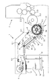
図1からわかるように、排紙装置1は加工方向で見て印刷機の最後の加工ステーションの後に続いている。このような加工ステーションは、印刷ユニット、または塗工ユニットなどの後処理ユニットであることもある。この実施形態では最後の加工ステーションは、オフセット方式で作動する、圧胴2.1を備えた印刷ユニット2である。この圧胴は、回転方向矢印5で示されている加工方向で、圧胴2.1とこれと協働するブランケット胴2.2との間の印刷間隙を通ってそれぞれの枚葉紙3を案内する。そうして、この実施例ではそれに続いて、圧胴2.1に配置されていて枚葉紙3の先行する端部にあるくわえ端で枚葉紙3を把持するために設けられているくわえづめ列を開いて、1回転(eintourig)搬送胴2.3のくわえづめ列に枚葉紙を引き渡す。次いで対応する枚葉紙3の引き渡しが1回転搬送胴2.3からさらに別の、この実施形態では半回転(halbtourig)搬送胴2.4へと行われ、この搬送胴が最終的に枚葉紙3を排紙装置1に引き渡す。排紙装置は2つのエンドレスの搬送チェーンを含んでおり、その搬送チェーンのそれぞれは、排紙装置1のそれぞれの側壁の近傍で、閉じたチェーン軌道に沿って適正な動作で循環している。それぞれの搬送チェーンは、回転軸が互いに一直線に並んでいる同期して駆動される2つの駆動チェーンホイール7の一方にそれぞれ巻きつき、この実施形態では駆動チェーンホイール7に対して加工方向に関して下流にあるそれぞれ1つの方向転換チェーンホイール8を介して案内され、その結果、搬送チェーン6のそれぞれは、閉じたチェーン軌道を通って走行している。両方の搬送チェーン6の間には、くわえづめ9.1を備えていて搬送チェーンに支持されたくわえづめブリッジ9が延びている。くわえづめ9.1は、搬送胴2.4に設けられているくわえづめの間の隙間を通りぬけ、このときくわえづめ9.1は、搬送胴2.4に配置されたくわえづめが開く直前に枚葉紙3の先行する端部にある前述したくわえ端を把持して当該枚葉紙3を受け取り、これを枚葉紙案内装置10を経由して向こう側の制動ステーション11へと搬送し、この制動ステーション11に枚葉紙3を引き渡した後に開く。枚葉紙3は、制動ステーション11で処理速度にくらべて低い堆積速度へ減速されて、この堆積速度に達した後に最終的に解放され、その結果、遅くなったそれぞれの枚葉紙3は最後に前縁ストッパ12に当たり、この前縁ストッパおよびこれに対向する後縁ストッパ13で向きを揃えられて、先行および後続する枚葉紙3の一方または双方とともにパイル14を形成する。パイル14は、パイル14が成長すると共に昇降装置によって一塊りにして降下させることができる。図1には、この昇降装置のうち、パイル14を支持するプラットフォーム15と、これを支持する、鎖線で示されている昇降チェーン16だけが描かれている。
【0014】
搬送チェーン6は、一方の駆動チェーンホイール7と他方の方向転換チェーンホイール8との間の行程に沿って、チェーンホイール間部分のチェーン軌道を規定する図示しないチェーンガイドレールによって案内される。本実施形態の場合では枚葉紙3は図1の主として下側に位置する伝動チェーンによって、次に記す搬送区間に沿って搬送される。その搬送区間は、圧胴2.4から排紙装置1へ枚葉紙3が引き渡される位置を起点として、方向転換チェーンホイール8の領域に配置されたカム4が、図示されていないローラレバーを作動する位置まで延びていて、このローラレバーはくわえづめ9.1と作用結合している。このローラレバーの動作によって、ばね応力の作用によって閉じられていたくわえづめ9.1は、枚葉紙3を解放しながら開くことができる。主として、下側に位置している伝動チェーンが走行しているチェーン軌道の区域の形状に倣って、このチェー軌道に対向して、枚葉紙案内装置10に枚葉紙案内面17が形成されている。この枚葉紙案内面と、この上を搬送されていくそれぞれの枚葉紙3との間で働くように、支持エアクッションが形成されると有利である。そのために枚葉紙案内装置10は枚葉紙案内面17に開口する噴出空気ノズルを装備している。その噴出空気ノズルについては、図1には、それを代表する全体のみが、象徴的な表現で、接続用パイプ18として描かれている。
【0015】
印刷された枚葉紙3がパイル14で互いにくっつくのを防ぐため、駆動チェーンホイール7から制動ステーション11へ至る枚葉紙3の行程には、乾燥機19と散粉装置20が設けられている。
【0016】
乾燥機19によって枚葉紙案内面17が過度に熱せられるのを防ぐため、枚葉紙案内装置10には、冷却剤の循環装置が組み込まれている。図1では象徴的に枚葉紙案内面17に配置された冷却剤槽23に接続された吸入パイプ21と排出パイプ22によって示されている。
【0017】
本図の実施形態では上述した搬送区間は、水平な区域と、これに対して上流に位置していて水平な区域の方に向かって上昇している枝部と、この枝部に対して上流に位置する枚葉紙方向転換領域24とを有する。この枚葉紙方向転換領域は、枚葉紙が片面だけ印刷されている場合には他に措置を講じなければ枚葉紙が無秩序な動きをして、まだ刷りたてのインキの裏移りを招きかねないという意味で問題のある領域である。
【0018】
この措置のひとつは、例えば、くわえづめ軌道の、くわえづめ9.1が通過する、枚葉紙方向転換領域をなしている区域の半径方向外側に、くわえづめ9.1の進行方向で見てほぼ枚葉紙方向転換領域24の区間に、空気圧で作動可能な枚葉紙案内装置10’を設けることである。この枚葉紙案内装置10’の有利な実施形態は、本出願人によって、すでに米国特許明細書5,456,179号に記載されている。ここでは、特に、当該実施形態を援用する。
【0019】
前述の措置のさらに別の措置は、枚葉紙方向転換領域24を通過する枚葉紙3に、これを支持する噴出エアカーテン25を向けることである。この噴出エアカーテンは、噴出空気源26によって噴出される。この噴出空気源26は、最初に述べた排紙装置とは対照的に定位置に配置されているのではなく、くわえづめ9.1と同じ方向に枚葉紙方向転換領域24を通過する。
【0020】
すでに上述したように、必ずしも必須ではないが望ましい態様としては設けられている噴出エアカーテン25がくわえづめ9.1と同期して枚葉紙方向転換領域24を通過するという構成の場合には、この実施形態で意図されているように、噴出空気源26が、駆動チェーンホイール7によって形成されるチェーンホイール対とともに1つの構成ユニットを構成することによって、枚葉紙搬送装置の特に簡単な構造を得ることができる。
【0021】
この場合、噴出空気源26は、望ましくは、駆動チェーンホイール7の回転軸に平行に配置され、一列の噴出空気口26.2(そのうちの1つが図3に描かれている)を長手方向に備えている管26.1を使用して構成されている。しかし、このように構成された噴出空気源26が有利であるけれど、枚葉紙方向転換領域24を上述した方向に通過する噴出エアカーテン25を構造的に他の態様に構成した圧縮空気源から噴出させることを排除するものではない。
【0022】
図2および図4に示すように、上述した構成ユニットはこの実施形態では下記のように構成されている。
【0023】
両方の駆動チェーンホイール7は、ジャーナル27.1および27.2を有するチェーンホイール軸27に対して回転しないように、チェーンホイール軸27に結合されている。それぞれのチェーンホイール7の近傍においては、チェーンホイール軸27が、その円周方向に位置調節可能でかつ摩擦力でこれ(チェーンホイール軸27)と係合されている各ハブ28を支持している。ハブ28にはスポーク29が長手方向に調節できるように取りつけられており、しかも半回転の駆動チェーンホイール7のこの実施例では、ハブ28ごとに2本のスポークが取りつけられている。駆動チェーンホイール7が半回転の仕様で運転されるので、特に図4からわかるとおり、2つの噴出空気源26が設けられ、それらの噴出空気源26のそれぞれは、すでに上述したように、1本の管26.1で構成されているている。それぞれの管26.1はその端部でそれぞれ1つの、管26.1から突き出ているピン30で閉止されている。それぞれ、駆動チェーンホイール7の半径方向外側に位置する、スポーク29の端部にあって駆動チェーンホイール7の回転軸に対してそれぞれ平行に向く穴が、これらのピン30のそれぞれを摺動可能に穴の中に受け入れている。したがって、それぞれ、このように組み立てられて噴出空気源を形成するために用いられる管26.1は、当該管の長軸の周りに回転可能であり、一定の回転位置において止めネジ31で固定可能である。止めネジ31は、管26.1を支持するスポークの少なくとも1本に挿入されてピン30の1つに働く。その結果、噴出空気源26から、(ここでは上述した噴出ノズル列を備えている管26.1から)適正に吹き出される噴出エアカーテンの噴出方向は調整可能であり、望ましい実施態様としては、枚葉紙方向転換領域24を通過する枚葉紙の進行方向に対して傾向的に反対を向くように噴出方向が調整される。
【0024】
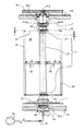
上に説明した、噴出空気源26と駆動チェーンホイール7とを含む構成ユニットは、ドラム本体32を形成し、該ドラム本体32は、枚葉紙搬送装置1の側壁33および34に設けられた軸受け孔33.1および34.1に、ジャーナル27.1および27.2を介して回転可能に収容されている。チェーンホイール軸27は、軸受け孔33.1と連通する中空スペース35がジャーナル27.1の中に生じるように中空に形成されている。このことは本実施形態においては、図4からわかるように、次のようにして実現される。すなわち、チェーンホイール軸27が、管27’と、その端部に溶接された軸部分27’’および27’’’とで構成されていて、これらのうち、軸部分27’’は貫通孔を備えていて、この貫通口が、管27’に開口する中空スペース35を形成する。
【0025】
ジャーナル27.1は、軸受け孔33.1の深さのうちの一部にだけこの軸受け孔の中に突入しており、軸受け孔33.1の、チェーンホイール軸27と反対側の端部は、接続ニップル37を有するキャップ36によって閉止されていて、この接続ニップルを介して軸受け孔33.1は、圧縮空気生成器38に接続することが可能である。
【0026】
それぞれの噴射空気源26を形成するために設けられている管26.1のそれぞれと、チェーンホイール軸27の管27’との間には、柔軟な導管39によって作られた連結部があるので、最終的には、それぞれの噴出空気源26は、中空スペース35と連通している。
【0027】
このようにして、周回する噴出空気源26への圧縮空気の供給が、回転ダクトを必要とすることなく可能になる。
【0028】
噴出空気源26のそれぞれを支持しているスポーク29はその長手方向に調節可能にハブ28に固定されているので、噴出エアカーテン25は、調節範囲にある、搬送区間までの間隔Aで枚葉紙方向転換領域24を通過することができる。
噴出空気源26を形成する管26.1は、スポーク29を介して、円周方向に調節できるようにチェーンホイール軸27と結合されたハブ28によって支持されているので、噴出エアカーテン25は枚葉紙方向転換領域24を、くわえづめ9.1に対する調整可能な位相角φの角度位置で通過することができる。
【0029】
また、くわえづめ9.1は、くわえづめブリッジ9を支持する搬送チェーン6が巻き付いている駆動チェーンホイール37を特に含んでいるドラム本体32の適正な回転動作によって駆動されて、枚葉紙方向転換領域を通過する。
【0030】
ドラム本体32が適正な回転動作をするために、チェーンホイール軸27は本実施形態では、駆動手段と結合された歯車列の構成要素である駆動歯車40に対して回転しないように、該駆動歯車40に結合されている。
【0031】
ここまでに説明した排紙装置は、以下に説明するようにさらに別の理由からも格別に有利であることが判明している。
【0032】
図1が示すように、枚葉紙案内装置10は、枚葉紙展開装置41から始まる。枚葉紙展開装置41は、通常は枚葉紙が片側に印刷されている場合に、(ここでは枚葉紙案内装置10と反対側を向いた枚葉紙の側に)用いられて、枚葉紙の両方の側縁に対して垂直な展開(巻いてある紙等を広げること:Entrollung)隙間の負圧によって枚葉紙をこの隙間に引き込む。しかし、この負圧は、それぞれの枚葉紙が枚葉紙展開装置41に接触した場合に初めてこの負圧の方向に完全に有効になる。この枚葉紙展開装置は通常、枚葉紙方向転換領域の出口領域のすぐ近傍に配置されているので、枚葉紙方向転換領域24を通過する噴出エアカーテン25によって、枚葉紙展開装置への枚葉紙3の接触は助長される。
【0033】
さらに、噴出空気源26がスポーク29によって支持された管26.1の形をとるという望ましい実施態様は、清掃の目的のために枚葉紙方向転換領域24に手が届きやすいという利点や、枚葉紙方向転換領域24を見通し易いという利点を生じ、このことは特に枚葉紙が両面に印刷されている場合に、空気圧で作動可能な枚葉紙案内装置10’を調整する際に極めて有用である。
【0034】
さらに、噴出エアカーテン25の噴出方向、噴出空気源と枚葉紙方向転換領域24の搬送区間との間隔、および枚葉紙方向転換領域24を通過するくわえづめ9.1に対する噴出空気源26の位相角φのパラメータに関して噴出空気源26が調整可能であることによって、異なる連量や異なる剛性をもつ枚葉紙に及ぼす噴出エアカーテン25の作用について妥協が得られるように、ドラム本体32に対する噴出エアカーテン25の空間的な位置を調整することが可能になる。当然ながら、上述のパラメータのいくつかだけを、多数の異なる印刷ジョブのために維持することも可能である。
【0035】
噴出エアカーテンの作用の効果に関するさらに別の可能性は、噴出空気源26に供給される圧力を変えることである。このことは図4の中で調整可能な絞り42で示唆されている。
【0036】
図5には、噴出空気源26から噴出カーテン25が周期的に噴出される実施形態が示されている。この例では、噴出空気源26と両方の駆動チェーンホイール7とを包含する構成ユニットが、ドラム本体32’として示されている。図5のドラム本体32’は、図4のドラム本体32と原理的には同じであるけれど、図4のドラム本体32は半回転式で図5のものは1回転式である。したがって、図5のドラム本体32’は、噴出空気源26として働く管26.1を1本しか備えていない点で図4のドラム本体32と異なっている。周期的な噴出を実現するために、図4の実施例に対応する軸受け孔33.1は、切換弁43を介して、圧縮空気生成器38と接続可能で、切換弁43は、ここでは例としてドラム本体32’と正しく同期して回転するカム44によって、機械的に、交互に、開いたり閉じたりする。この場合、ドラム本体32’に対するカム44の位相位置は、噴出空気源26が枚葉紙方向転換領域24を通過するときに切換弁43が開くように調整されている。
【0037】
図4に示す半回転のドラム本体32を形成するために設けられている2つの管26.1を圧縮空気で、図5の管26.1と同じように、しかし交互に、周期的に作動することは、同様のやり方で、かつ、ドラム本体32とその圧縮空気生成器38への接続を次のように改良することによって実現される。すなわち、噴出エアカーテン25を適正に噴出する両方の管26.1が互いに独立に圧縮空気生成器38に接続することが可能であるように改良する。
【図面の簡単な説明】
【図1】枚葉紙を加工する印刷機の、排紙装置を含んでいる部分を示す概略図であり、この図では、噴出空気源の実施形態は、それぞれくわえづめ列が配置されたくわえづめブリッジを支持している搬送チェーンが巻き付いているチェーンホイール装置のチェーンホイール対を有する構成ユニットを形成している。
【図2】くわえづめ列と協働する、チェーンホイール対と噴出空気源とで形成された図1の構成ユニットを示す、図1に対応する図である。
【図3】噴出エアカーテンを示す図1の詳細図である。
【図4】図2の構成ユニットを示す平面図である。
【図5】1回転式で走行する噴出エアカーテンの場合のために図4に対して変更された構成ユニットを示す平面図である。
【符号の説明】
1 排紙装置
2 印刷ユニット
2.1 圧胴
2.2 ブランケット胴
2.3 搬送胴
2.4 搬送胴
3 枚葉紙
4 カム
5 回転方向矢印
6 搬送チェーン
7 駆動チェーンホイール
8 方向転換チェーンホイール
9 くわえづめブリッジ
9.1 くわえづめ
10 枚葉紙案内装置
11 制動ステーション
12 前縁ストッパ
13 後縁ストッパ
14 パイル
15 プラットフォーム
16 昇降チェーン
17 枚葉紙案内面
18 接続用パイプ
19 乾燥機
20 散粉装置
21 吸入パイプ
22 排出パイプ
23 冷却剤槽
24 枚葉紙方向転換領域
25 噴出エアカーテン
26 噴出空気源
26.1 管
27 チェーンホイール軸
27.1 ジャーナル
27.2 ジャーナル
28 ハブ
29 スポーク
30 ピン
31 止めネジ
32 ドラム本体
32’ ドラム本体
33 側壁
33.1 軸受け孔
34 側壁
34.1 軸受け孔
35 中空スペース
36 キャップ
37 接続ニップル
38 圧縮空気生成器
39 導管
40 駆動歯車
41 枚葉紙展開装置
42 絞り
43 切換弁
44 カム[0001]
BACKGROUND OF THE INVENTION
[Technical Field] The present invention relates to a paper sheet processing machine, in particular, a paper discharge device for a printing machine, and a gripper row for properly pulling a paper sheet along a conveyance section, and a paper discharge device in a proper circulation direction. A pair of chain wheels that rotate around a common axis of rotation that forms an endless transfer chain that meshes with the transfer chain and forms a direction change area of the transfer section; A machine for processing a sheet comprising a sheet of air passing through a sheet direction changing area, and an air source for blowing out an air curtain capable of being blown to the side facing the rotation axis, in particular The present invention relates to a paper discharge device of a printing press.
[0002]
[Prior art]
Such a paper discharge device is known, for example, from the publication US 5,456,178. This publication discloses an air curtain which is blown out from a blower tube device. The air curtain is oriented toward the periphery of a transfer area in which each one of the gripper rows pulls each sheet from a cylinder guiding the sheet. When the rear edge of each sheet passes over this transfer area, the sheet is blown down from this edge, ie towards the direction of travel of the sheet. . However, this has a very undesirable effect on the stable running of the sheet.
[0003]
In the case of sheets with a relatively high bending stiffness, in particular in the case of cartons, the known blast tube device does not provide the desired effect of preventing the sheets from hitting the machine parts. Such a type of sheet would rather collide with known blast tube components.
[0004]
Publication DE-AS2017417 discloses a drum equipped with a gripper row in which the gripper row receives a sheet of paper from the impression cylinder of the printing unit and delivers it continuously to the next printing unit of the rotary printing press. . The drum has a mantle, which is not described in detail for reasons, and the mantle supports the sheet in the circumferential direction of the drum along only part of its extent. A support device for supporting the sheet with air pressure is provided in a space covered by the sheet between the outer jacket that supports the sheet and the gripper row. According to one embodiment, the support device includes a blast tube parallel to the drum axis, the blast tube being disposed near an envelope circle that abuts the drum and directed radially outward with respect to the drum axis. It has a spout and is rotated with the drum. Using this support device, when the sheet comes out of the printing gap, it prevents curling that adheres to the blanket cylinder of each printing unit from occurring on the sheet, thereby causing a difference in registration. The purpose of preventing this is being pursued.
[0005]
[Problems to be solved by the invention]
In the paper discharge device of the type described at the beginning (“Technical field to which the invention belongs”), there is no problem associated with preventing the difference in registration. In this case, there is a general problem that the printed sheets are handed over to the sheet conveyor without turning over and put together into a pile. One of the conditions that must be met in this connection is the stable running of the sheet. It is an object of the present invention to provide a paper discharge device of the type mentioned at the beginning so as to prevent an unfavorable influence on the stable running of the sheets passing through the sheet turning area on the side of the jet air curtain. It is to improve.
[0006]
[Means for Solving the Problems]
In order to achieve this object, in the present invention, while the sheet passing through the sheet direction changing region is being sprayed by the jetting air curtain, the jetting air curtain itself has a gripper that changes the direction of the sheet. passing through the same-direction twin-leaf paper redirecting areas to the direction passing through the area, and has a hollow space having a journal which is accommodated in the bearing hole of the side wall, the drum body for supporting is provided a jet air source It is intended that the blown air source communicates with the hollow space, the hollow space communicates with the bearing hole, and the bearing hole is connectable with the compressed air generator .
[0007]
With this type of configuration of the paper discharge device, it is possible to avoid spraying the rear area of each sheet as described above, in particular. The reason for this is particularly when the angular velocity of the gripper passing through the sheet redirecting region and the angular velocity of the ejecting air curtain passing through the sheet redirecting region are in perfect agreement (this is not necessarily essential). Is a preferred embodiment, as will be described later), and the relative position of the blown air curtain with respect to the gripper and thus with respect to the sheet of paper that the gripper pulls does not change within the sheet turning region. There is.
[0008]
In an advantageous embodiment, the ejection direction of the ejection air curtain is a trend to the opposite direction to the traveling direction of the sheet passing through the sheet deflecting region, therefore, the ejection direction is rectangular direction conversion region It is intended to have a component in the direction opposite to the direction of travel of the transport chain passing through. This allows the blown air to be blown onto the sheet when it is intended as a desirable mode to blow the blown air curtain in the area of the sheet that immediately follows the gripper that is pulling the sheet. Can be performed over almost the entire spread in the direction of travel of the sheet, so that the squirt air curtain is almost comparable to the spread in the direction of travel of the sheet before it hits the sheet. There is no need to have a wide spread. Thus, the blast air source can be made compact accordingly, whereby the blast air source is formed in an advantageous embodiment using only nozzle rows arranged transversely to the direction of travel. Can do.
[0009]
In a further advantageous embodiment, the ejection direction of the ejection air curtain is adjustable, the ejection air curtain passes through the sheet redirecting region at an adjustable interval with respect to the conveying section, and the ejection air curtain is It is intended to pass through the sheet turning region with an adjustable phase angle relative to the gripper.
[0010]
Utilizing at least one of these conditions, or utilizing a combination of one of these conditions and at least one other condition, without requiring the ejection air curtain to be modified with respect to its air pressure parameters The ability to support the sheet passing through the sheet turning area can be adapted to a relatively wide range of sheet weights and a variety of stiffness, as well as to accommodate different paper sizes of the sheet be able to. Thereby, the cost required to produce the blown air curtain is relatively low.
[0011]
In yet another embodiment, it is contemplated as an embodiment where it is desirable for the source of blast air to blow the blast air curtain periodically. As a result, the blowout of the blown air curtain can be limited to a time interval such that the blown air curtain passes through the sheet turning area in the same direction as the gripper. Unfavorable flow conditions that occur outside can be avoided around the conveyed sheet.
[0012]
DETAILED DESCRIPTION OF THE INVENTION
Next, embodiments of the present invention will be described with reference to the drawings.
[0013]
As can be seen from FIG. 1, the paper discharge device 1 follows the last processing station of the printing press in the processing direction. Such a processing station may be a printing unit or a post-processing unit such as a coating unit. In this embodiment, the last processing station is a
[0014]
The transport chain 6 is guided along a stroke between one
[0015]
In order to prevent the printed sheets 3 from sticking to each other at the
[0016]
In order to prevent the sheet guide surface 17 from being heated excessively by the
[0017]
In the embodiment of the present figure, the above-described conveyance section includes a horizontal section, a branch section that is located upstream of the transport section and that rises toward the horizontal section, and an upstream section that is upstream of the branch section. And a sheet
[0018]
One such measure is, for example, in the direction of travel of gripper 9.1, radially outward of the section of the gripper trajectory where gripper 9.1 passes and forms the sheet turning area. The
[0019]
Yet another of the above measures is to direct the blown
[0020]
As already described above, as a desirable mode, though not necessarily essential, in the case of the configuration in which the provided
[0021]
In this case, the
[0022]
As shown in FIGS. 2 and 4, the above-described constituent units are configured as follows in this embodiment.
[0023]
Both
[0024]
The above-described constituent unit including the
[0025]
The journal 27.1 protrudes into the bearing hole only at a part of the depth of the bearing hole 33.1. The end of the bearing hole 33.1 opposite to the
[0026]
Since there is a connection made by a
[0027]
In this way, it is possible to supply compressed air to the circulating
[0028]
Since the
The pipe 26.1 forming the
[0029]
Further, the gripper 9.1 is driven by an appropriate rotational movement of the
[0030]
In order for the drum
[0031]
The paper discharge device described so far has been found to be particularly advantageous for further reasons as will be described below.
[0032]
As shown in FIG. 1, the
[0033]
Furthermore, the preferred embodiment in which the
[0034]
Further, the ejection direction of the
[0035]
Yet another possibility for the effect of the action of the blown air curtain is to change the pressure supplied to the blown
[0036]
FIG. 5 shows an embodiment in which the
[0037]
The two tubes 26.1 provided to form the half-rotating
[Brief description of the drawings]
FIG. 1 is a schematic view showing a portion of a printing machine for processing a sheet that includes a paper discharge device. In this figure, the embodiment of the blown air source is a gripper in which a gripper row is arranged. A component unit having a chain wheel pair of a chain wheel device around which a transport chain supporting a bridge is wound is formed.
2 is a view corresponding to FIG. 1, showing the component unit of FIG. 1 formed by a pair of chain wheels and a source of blown air, cooperating with a gripper row.
FIG. 3 is a detailed view of FIG. 1 showing an ejection air curtain.
4 is a plan view showing the constituent unit of FIG. 2; FIG.
FIG. 5 is a plan view showing a structural unit that is modified with respect to FIG. 4 for the case of an ejection air curtain that travels in one rotation.
[Explanation of symbols]
DESCRIPTION OF SYMBOLS 1
Claims (8)
前記枚葉紙方向転換領域(24)を通過する枚葉紙(3)に噴射エアカーテン(25)を吹き付けている間に、前記噴射エアカーテン自身は、くわえづめ(9.1)が前記枚葉紙方向転換領域(24)を通過する方向と同じ方向に前記枚葉紙方向転換領域(24)を通過し、
中空スペース(35)を持っていて側壁(33)の軸受孔(33.1)に収容されているジャーナル(27.1)を有し、前記噴出空気源(26)を支持するドラム体(32,32')が設けられており、前記噴出空気源(26)が前記中空スペース(35)と連通し、前記中空スペース(35)は前記軸受孔(33.1)と連通しており、前記軸受孔(33.1)は圧縮空気生成器(38)と接続可能である、
ことを特徴とする、枚葉紙を加工する機械の排紙装置。A paper discharge device of the machine processing the sheet, sheet gripper and columns pulled along the leaf paper properly conveying track, properly caused to run in the circumferential direction of the sheet discharging device, supporting the gripper row An endless transport chain, a pair of chain wheels meshing with the transport chain and forming a direction change area of the transfer section, rotatable around a common rotation axis, and passing through the sheet direction change area A sheet discharge device of a machine for processing a sheet, comprising: an ejection air source that ejects an air curtain that can be sprayed on a side of the sheet facing the rotation axis;
While the jet air curtain (25) is being blown onto the sheet (3) passing through the sheet direction changing area (24), the jet air curtain itself has a gripper (9.1) that is held by the sheet. Pass through the sheet redirecting area (24) in the same direction as passing through the sheet redirecting area (24) ,
A drum body (32) having a hollow space (35) and having a journal (27.1) accommodated in a bearing hole (33.1) of a side wall (33) and supporting the blown air source (26). 32 ′), the blown air source (26) communicates with the hollow space (35), the hollow space (35) communicates with the bearing hole (33.1), The bearing hole (33.1) is connectable with the compressed air generator (38),
A paper discharge device for a machine for processing a sheet.
Applications Claiming Priority (2)
| Application Number | Priority Date | Filing Date | Title |
|---|---|---|---|
| DE19855713 | 1998-12-03 | ||
| DE19855713-2 | 1998-12-03 |
Publications (3)
| Publication Number | Publication Date |
|---|---|
| JP2000168048A JP2000168048A (en) | 2000-06-20 |
| JP2000168048A5 JP2000168048A5 (en) | 2006-11-16 |
| JP4633877B2 true JP4633877B2 (en) | 2011-02-16 |
Family
ID=7889794
Family Applications (1)
| Application Number | Title | Priority Date | Filing Date |
|---|---|---|---|
| JP34434999A Expired - Fee Related JP4633877B2 (en) | 1998-12-03 | 1999-12-03 | Paper discharge device for machines that process sheets |
Country Status (5)
| Country | Link |
|---|---|
| US (1) | US6401611B1 (en) |
| EP (1) | EP1006068B1 (en) |
| JP (1) | JP4633877B2 (en) |
| AT (1) | ATE249384T1 (en) |
| DE (2) | DE59906937D1 (en) |
Families Citing this family (7)
| Publication number | Priority date | Publication date | Assignee | Title |
|---|---|---|---|---|
| DE102004053099B4 (en) * | 2003-11-18 | 2016-12-22 | Heidelberger Druckmaschinen Ag | Method for smoothing a sheet of printing material |
| JP4709605B2 (en) * | 2004-07-27 | 2011-06-22 | ハイデルベルガー ドルツクマシーネン アクチエンゲゼルシヤフト | Machine for processing sheets of printed material |
| DE102006049648A1 (en) * | 2006-10-20 | 2008-04-24 | Heidelberger Druckmaschinen Ag | Method for controlling a powder sprayer |
| CN101269760B (en) * | 2007-03-23 | 2011-11-16 | 海德堡印刷机械股份公司 | Paper delivery drum and perfecting press |
| JP2008279754A (en) * | 2007-04-09 | 2008-11-20 | Dainippon Screen Mfg Co Ltd | Printing machine |
| US20080265493A1 (en) * | 2007-04-30 | 2008-10-30 | Robert Wall | Air delivery device for printing and coating applications |
| DE102009000219A1 (en) * | 2009-01-14 | 2010-07-15 | Koenig & Bauer Aktiengesellschaft | Delivery device for e.g. sheet-fed offset rotary printing press, has sheet conveyor system comprising circulating pick-up carriers that are approximately linearly guided before, during and after sheet transfer |
Citations (1)
| Publication number | Priority date | Publication date | Assignee | Title |
|---|---|---|---|---|
| JPH07508962A (en) * | 1992-07-20 | 1995-10-05 | ハイデルベルガー ドルツクマシーネン アクチエン ゲゼルシヤフト | Printing machine sheet guide cylinder |
Family Cites Families (12)
| Publication number | Priority date | Publication date | Assignee | Title |
|---|---|---|---|---|
| DE2017417B2 (en) | 1970-04-11 | 1972-07-20 | Maschf Augsburg Nuernberg Ag | Sheet transfer drum on sheet-fed rotary offset printing machines |
| DE2354418C3 (en) | 1973-10-31 | 1980-04-17 | Heidelberger Druckmaschinen Ag, 6900 Heidelberg | Sheet transfer drum for printing machines |
| JPH025950Y2 (en) * | 1981-02-03 | 1990-02-14 | ||
| DE8437444U1 (en) * | 1984-12-21 | 1985-03-21 | Heidelberger Druckmaschinen Ag, 6900 Heidelberg | BLOWING DEVICE ON THE CHAIN DISPLAY OF ROTARY PRINTING MACHINES |
| US4919048A (en) * | 1986-08-01 | 1990-04-24 | Tyler Jack D | Apparatus for preventing contact of wet ink sheets with printing press delivery mechanisms and for drying said wet ink |
| JPH0742723Y2 (en) * | 1987-03-05 | 1995-10-04 | 株式会社小森コーポレーション | Paper transport device for sheet-fed rotary printing press |
| US4836104A (en) * | 1987-06-05 | 1989-06-06 | Duarte Products, Inc. | Sheet transfer mechanism for a freshly printed sheet |
| DD281797A5 (en) * | 1988-12-14 | 1990-08-22 | Polygraph Leipzig | ARC DIRECTION IN THE OUTLET DRIVE AREA OF PRINTING MACHINES |
| DE4244499C2 (en) * | 1992-12-30 | 1995-04-06 | Heidelberger Druckmasch Ag | Printing machine with sheet guiding surface |
| DE59409290D1 (en) * | 1994-01-17 | 2000-05-18 | Heidelberger Druckmasch Ag | Bow guide cylinder |
| DE4436955C2 (en) | 1994-10-15 | 1999-11-11 | Roland Man Druckmasch | Device for contactless sheet transport |
| JP2786433B2 (en) * | 1995-12-15 | 1998-08-13 | エム アー エヌ ローラント ドルツクマシーネン アクチエンゲゼルシヤフト | Cylinder for guiding sheets for printing press |
-
1999
- 1999-11-11 EP EP99122013A patent/EP1006068B1/en not_active Expired - Lifetime
- 1999-11-11 AT AT99122013T patent/ATE249384T1/en not_active IP Right Cessation
- 1999-11-11 DE DE59906937T patent/DE59906937D1/en not_active Expired - Lifetime
- 1999-11-12 DE DE19954554A patent/DE19954554A1/en not_active Withdrawn
- 1999-12-03 US US09/454,199 patent/US6401611B1/en not_active Expired - Fee Related
- 1999-12-03 JP JP34434999A patent/JP4633877B2/en not_active Expired - Fee Related
Patent Citations (1)
| Publication number | Priority date | Publication date | Assignee | Title |
|---|---|---|---|---|
| JPH07508962A (en) * | 1992-07-20 | 1995-10-05 | ハイデルベルガー ドルツクマシーネン アクチエン ゲゼルシヤフト | Printing machine sheet guide cylinder |
Also Published As
| Publication number | Publication date |
|---|---|
| EP1006068A3 (en) | 2001-04-04 |
| DE59906937D1 (en) | 2003-10-16 |
| DE19954554A1 (en) | 2000-06-08 |
| US6401611B1 (en) | 2002-06-11 |
| EP1006068A2 (en) | 2000-06-07 |
| EP1006068B1 (en) | 2003-09-10 |
| ATE249384T1 (en) | 2003-09-15 |
| JP2000168048A (en) | 2000-06-20 |
Similar Documents
| Publication | Publication Date | Title |
|---|---|---|
| US10940699B2 (en) | Modular machine arrangement for sequential processing of sheets | |
| US10173439B2 (en) | Printing press assembly having a plurality of processing stations for processing sheets and method for operating the printing press assembly | |
| US20190070846A1 (en) | Device for overlapping sheets | |
| JP4657479B2 (en) | Device for transporting sheets of paper for rotary printing presses | |
| US8561987B2 (en) | Machine for processing sheets | |
| US10052886B2 (en) | Method and apparatus for arranging sheets in a shingled position | |
| JP5361168B2 (en) | Device for reversing a sheet of paper while it is transported through a printing press | |
| JPH03118156A (en) | Tensile roller device for web printing machine | |
| JPH1110833A (en) | Sheet-feed rotary press | |
| JP4633877B2 (en) | Paper discharge device for machines that process sheets | |
| US6598872B1 (en) | Sheet braking device with replaceable support element | |
| JP4707828B2 (en) | Sheet brake device for paper discharge device of sheet processing machine | |
| CN117320985A (en) | Printing machine with a plurality of processing stations for processing individual sheets | |
| JP2000289184A (en) | Sheet delivering device for sheet-fed printer | |
| JP3238332B2 (en) | Sheet guide for sheet-fed printing press | |
| JP2000053303A5 (en) | ||
| US7000917B2 (en) | Sheet-guiding device in a sheet-processing machine | |
| US6684774B2 (en) | Sheet-fed rotary printing press | |
| JP5010066B2 (en) | Printing machine guide apparatus for processing sheets and sheet processing machine equipped with the guide apparatus | |
| JP2002302317A (en) | Paper delivery device for machine processing paper sheets | |
| JP2001213545A (en) | Delivery of machine handling flat object to be printed | |
| JP4450890B2 (en) | Sheet-fed rotary printing press | |
| JP3703796B2 (en) | Sheet paper guide device having a guide surface in a printing press | |
| JP5242932B2 (en) | How to spray powder on printed sheets | |
| JP2000508594A (en) | Reversing device for printing presses, especially sheet-fed web offset presses |
Legal Events
| Date | Code | Title | Description |
|---|---|---|---|
| A521 | Request for written amendment filed |
Free format text: JAPANESE INTERMEDIATE CODE: A523 Effective date: 20061003 |
|
| A621 | Written request for application examination |
Free format text: JAPANESE INTERMEDIATE CODE: A621 Effective date: 20061003 |
|
| RD03 | Notification of appointment of power of attorney |
Free format text: JAPANESE INTERMEDIATE CODE: A7423 Effective date: 20061003 |
|
| A977 | Report on retrieval |
Free format text: JAPANESE INTERMEDIATE CODE: A971007 Effective date: 20091102 |
|
| A131 | Notification of reasons for refusal |
Free format text: JAPANESE INTERMEDIATE CODE: A131 Effective date: 20091111 |
|
| A521 | Request for written amendment filed |
Free format text: JAPANESE INTERMEDIATE CODE: A523 Effective date: 20100210 |
|
| TRDD | Decision of grant or rejection written | ||
| A01 | Written decision to grant a patent or to grant a registration (utility model) |
Free format text: JAPANESE INTERMEDIATE CODE: A01 Effective date: 20101020 |
|
| A01 | Written decision to grant a patent or to grant a registration (utility model) |
Free format text: JAPANESE INTERMEDIATE CODE: A01 |
|
| A61 | First payment of annual fees (during grant procedure) |
Free format text: JAPANESE INTERMEDIATE CODE: A61 Effective date: 20101118 |
|
| R150 | Certificate of patent or registration of utility model |
Ref document number: 4633877 Country of ref document: JP Free format text: JAPANESE INTERMEDIATE CODE: R150 Free format text: JAPANESE INTERMEDIATE CODE: R150 |
|
| FPAY | Renewal fee payment (event date is renewal date of database) |
Free format text: PAYMENT UNTIL: 20131126 Year of fee payment: 3 |
|
| R250 | Receipt of annual fees |
Free format text: JAPANESE INTERMEDIATE CODE: R250 |
|
| R250 | Receipt of annual fees |
Free format text: JAPANESE INTERMEDIATE CODE: R250 |
|
| R250 | Receipt of annual fees |
Free format text: JAPANESE INTERMEDIATE CODE: R250 |
|
| R250 | Receipt of annual fees |
Free format text: JAPANESE INTERMEDIATE CODE: R250 |
|
| R250 | Receipt of annual fees |
Free format text: JAPANESE INTERMEDIATE CODE: R250 |
|
| R250 | Receipt of annual fees |
Free format text: JAPANESE INTERMEDIATE CODE: R250 |
|
| LAPS | Cancellation because of no payment of annual fees |