JP4630938B2 - Color image forming apparatus and color image control method - Google Patents
Color image forming apparatus and color image control method Download PDFInfo
- Publication number
- JP4630938B2 JP4630938B2 JP2009283086A JP2009283086A JP4630938B2 JP 4630938 B2 JP4630938 B2 JP 4630938B2 JP 2009283086 A JP2009283086 A JP 2009283086A JP 2009283086 A JP2009283086 A JP 2009283086A JP 4630938 B2 JP4630938 B2 JP 4630938B2
- Authority
- JP
- Japan
- Prior art keywords
- color
- patch
- image forming
- patches
- values
- Prior art date
- Legal status (The legal status is an assumption and is not a legal conclusion. Google has not performed a legal analysis and makes no representation as to the accuracy of the status listed.)
- Expired - Fee Related
Links
Images


Description
本発明は、画像信号に基づいてカラー画像を形成するカラー画像形成装置に関し、特にその色度の調整に関するものである。 The present invention relates to a color image forming apparatus that forms a color image based on an image signal, and more particularly to adjustment of the chromaticity thereof.
近年、カラープリンタ、カラー複写機等の電子写真方式やインクジェット方式等を採用したカラー画像形成装置には、出力画像の高画質化が求められている。特に、濃度の階調とその安定性は、人間が下す画像の良し悪しの判断に大きな影響を与える。 In recent years, color image forming apparatuses employing an electrophotographic system such as a color printer or a color copying machine, an ink jet system, and the like have been required to improve the output image quality. In particular, the gradation of the density and its stability have a great influence on the judgment of the quality of an image given by a human.
ところが、電子写真方式の画像形成装置は、環境の変化や長時間の使用による装置各部の変動があると、得られる画像の濃度が変動してしまう。特に電子写真方式のカラー画像形成装置の場合、わずかな濃度の変動でもカラーバランスが崩れてしまう恐れがあるので、常に一定の階調−濃度特性を保つ必要がある。そこで、各色のトナーに対して、絶対湿度に応じた数種類の露光量や現像バイアスなどのプロセス条件、ルックアップテーブル(LUT)などの階調補正手段をもち、温湿度センサによって測定された絶対湿度に基づいて、その時のプロセス条件や階調補正の最適値を選択している。また、装置各部の変動が起こっても一定の階調−濃度特性が得られるように、各色のトナーで濃度検知用トナーパッチを中間転写体やドラム等の上に作成し、その未定着トナーパッチの濃度を未定着トナー用濃度検知センサで検知し、その検知結果より露光量、現像バイアスなどのプロセス条件にフィードバックをかけて濃度制御を行うことで、安定した画像を得るように構成している。 However, in an electrophotographic image forming apparatus, if there is a change in each part of the apparatus due to environmental changes or long-term use, the density of the obtained image will change. In particular, in the case of an electrophotographic color image forming apparatus, there is a possibility that the color balance may be lost even by a slight change in density, so it is necessary to always maintain a constant gradation-density characteristic. Therefore, the absolute humidity measured by the temperature / humidity sensor is provided for each color toner with gradation correction means such as several kinds of exposure amounts and development biases according to the absolute humidity, development bias, and lookup table (LUT). Based on the above, the process condition at that time and the optimum value for gradation correction are selected. In addition, a toner patch for density detection is created on the intermediate transfer body or drum with toner of each color so that a constant gradation-density characteristic can be obtained even if fluctuations occur in each part of the apparatus, and the unfixed toner patch The density of the toner is detected by a density detection sensor for unfixed toner, and the density control is performed by feeding back process conditions such as exposure amount and development bias based on the detection result, thereby obtaining a stable image. .
しかし、前記未定着トナー用濃度検知センサを用いた濃度制御はパッチを中間転写体やドラム等の上に形成し検知するもので、その後に行われる転写材への転写及び定着による画像のカラーバランスの変化については制御していない。転写材へのトナー像の転写における転写効率や、定着による加熱及び加圧によってもカラーバランスが変化する。この変化には、前記未定着トナー用濃度検知センサを用いた濃度制御では対応できない。そこで転写、定着後に転写材上の単色トナー画像の濃度又はフルカラー画像の色度を検知する濃度又は色度センサ(以下カラーセンサという)を設置し、濃度又は色度制御用カラートナーパッチ(以下パッチという)を転写材上に形成し、検知した濃度又は色度を露光量、プロセス条件、ルックアップテーブル(LUT)などのプロセス条件にフィードバックし、転写材上に形成した最終出力画像の濃度又は色度制御を行う画像形成装置が考えられている。このカラーセンサは、CMYKを識別したり、濃度又は色度を検知するために、例えば発光素子として赤(R)、緑(G)、青(B)を発光する光源を用いたり、発光素子は白色(W)を発光する光源を用いて、受光素子上に赤(R)、緑(G)、青(B)等の分光透過率が異なる3種のフィルタを形成したもので構成する。このことにより得られる3つの異なる出力、例えばRGB出力から、CMYKを識別したり濃度を検知することができる。また、RGB出力を線形変換等で数学的な処理をしたり、ルックアップテーブル(LUT)で変換することで色度を検知することができる。 However, density control using the density detection sensor for unfixed toner is to detect a patch by forming a patch on an intermediate transfer member, a drum, or the like, and color balance of the image by subsequent transfer to a transfer material and fixing. There is no control over changes. The color balance also changes depending on the transfer efficiency in transferring the toner image to the transfer material, and heating and pressurization by fixing. This change cannot be dealt with by density control using the density detection sensor for unfixed toner. Therefore, a density or chromaticity sensor (hereinafter referred to as a color sensor) for detecting the density of a single-color toner image on a transfer material or the chromaticity of a full-color image after transfer and fixing is installed, and a color toner patch for density or chromaticity control (hereinafter referred to as a patch). The density or chromaticity of the final output image formed on the transfer material by feeding back the detected density or chromaticity to the exposure conditions, process conditions, and process conditions such as a look-up table (LUT). An image forming apparatus that performs degree control is considered. This color sensor uses, for example, a light source that emits red (R), green (G), and blue (B) as a light emitting element in order to identify CMYK or detect density or chromaticity. Using a light source that emits white (W), three types of filters having different spectral transmittances such as red (R), green (G), and blue (B) are formed on the light receiving element. CMYK can be identified and density can be detected from three different outputs obtained by this, for example, RGB output. Further, the chromaticity can be detected by subjecting the RGB output to a mathematical process such as linear conversion or by converting the RGB output using a lookup table (LUT).
インクジェット方式のプリンタにおいても、インク吐出量の経時変化や環境差、インクカートリッジの個体差によりカラーバランスが変化し、階調−濃度特性を一定に保てない。そこで、プリンタの出力部付近にカラーセンサを設置し、転写材上のパッチの濃度又は色度を検知し、濃度又は色度制御を行うことが考えられている。 Even in an ink jet printer, the color balance changes due to a change in ink discharge amount with time, environmental differences, and individual differences of ink cartridges, and the gradation-density characteristics cannot be kept constant. Therefore, it is considered to install a color sensor near the output unit of the printer, detect the density or chromaticity of the patch on the transfer material, and perform density or chromaticity control.
濃度又は色度の制御方法は様々ある。例えば測定した濃度からガンマ特性制御や、測定した色度からカラーマッチングテーブルや色分解テーブルの補正を実行する手法等がある。 There are various methods for controlling density or chromaticity. For example, there is a method of performing gamma characteristic control from the measured density, or correcting the color matching table or color separation table from the measured chromaticity.
ここで、カラーセンサを用いてパッチの絶対濃度又は絶対色度を検知するためには、以下の理由によりセンサ出力校正用白色基準板等の、濃度又は色度の絶対値が既知である基準が必要となる。第1の理由は、センサを構成する発光素子や受光素子の分光特性のバラツキを校正する必要があるからである。第2の理由は、センサを構成する発光部及び受光部の経時変化や周囲温度変化により、同じパッチを検知しても出力が異なることがあるからである。第3の理由は、通常印字時に多くの転写材がセンサ付近を通過することにより、紙粉やトナー又はインクが飛び散り、センサ表面に堆積や付着することによりセンサ出力の低下を招くからである。 Here, in order to detect the absolute density or absolute chromaticity of a patch using a color sensor, there is a standard whose absolute value of density or chromaticity is known, such as a white reference plate for sensor output calibration, for the following reason. Necessary. The first reason is that it is necessary to calibrate the dispersion of the spectral characteristics of the light emitting element and the light receiving element constituting the sensor. The second reason is that the output may be different even if the same patch is detected due to the temporal change of the light emitting unit and the light receiving unit constituting the sensor and the ambient temperature change. The third reason is that a large amount of transfer material passes near the sensor during normal printing, so that paper dust, toner or ink scatters and accumulates on or adheres to the sensor surface, leading to a decrease in sensor output.
しかしながら、センサ出力校正用の基準としてよく使用される白色基準板は、高価であるだけでなく、センサと同様に白色基準板にも紙粉やトナー又はインクが飛び散り、基準板として使えなくなることもある。 However, the white reference plate that is often used as a reference for sensor output calibration is not only expensive, but, as with the sensor, paper dust, toner, or ink may scatter on the white reference plate, making it unusable as a reference plate. is there.
一方、センサ出力校正用の基準を用いずに、つまりセンサ出力の校正を行うことなくパッチの濃度又は色度を検知すると、前記理由の影響を受けた場合、センサ出力は実際のパッチの濃度又は色度とは異なった値を出力することとなる。その結果を用いて濃度又は色度制御を実行すると、カラーバランスはとれず、所望の階調−濃度特性も得られない。そればかりか、カラーバランスを逆に崩し、階調−濃度特性を悪化させることがある。 On the other hand, if the density or chromaticity of the patch is detected without using the sensor output calibration reference, that is, without calibrating the sensor output, the sensor output is the actual patch density or A value different from chromaticity is output. When density or chromaticity control is executed using the result, color balance cannot be achieved and desired gradation-density characteristics cannot be obtained. In addition, the color balance may be reversed and the gradation-density characteristics may be deteriorated.
さらには絶対色度を精度良く検知するためには高価な測色器で用いられるような高精度のXYZ型フィルタや反射光を分光する機能等を持つ必要があるが、このような機能を持つと非常に大きいコストアップとなり、このような機能を持ったカラーセンサをプリンタに搭載するのは現実的ではない。 Furthermore, in order to accurately detect absolute chromaticity, it is necessary to have a high-accuracy XYZ filter used in an expensive colorimeter, a function of splitting reflected light, and the like. Therefore, it is not realistic to install a color sensor having such a function in the printer.
そこで、カラーセンサでイエロー、マゼンダ、シアンを混色したプロセスグレーパッチとブラックによるグレーパッチの色度(L*a*b*やL*c*h*、XYZ等)を検知し、両パッチの色度を相対比較する手法が考えられる。 Therefore, the color sensor detects the chromaticity (L * a * b *, L * c * h *, XYZ, etc.) of the process gray patch mixed with yellow, magenta, and cyan and the gray patch of black, and the color of both patches. A method of comparing the degrees relative to each other can be considered.
しかしながら、前述のようにプロセスグレーが無彩色となるように補正を行うためにはプロセスグレーが無彩色となるシアン、マゼンタ、イエローの比率を求める手段が必要となる。 However, as described above, in order to perform the correction so that the process gray becomes an achromatic color, means for obtaining the ratio of cyan, magenta, and yellow at which the process gray becomes an achromatic color is required.
本発明は、このような状況のもとでなされたもので、カラーセンサで検知された色度からプロセスグレーが無彩色となるシアン、マゼンタ、イエローの比率を求めることのできるカラー画像形成装置、及びカラー画像の制御方法を提供することを目的とするものである。 The present invention has been made under such circumstances, and a color image forming apparatus capable of obtaining a ratio of cyan, magenta, and yellow in which process gray is an achromatic color from chromaticity detected by a color sensor , It is another object of the present invention to provide a color image control method .
前記目的を達成するため、本発明では、カラー画像形成装置を次の(1)ないし(5)、カラー画像の制御方法を(6)のとおりに構成する。 In order to achieve the above object, in the present invention, the color image forming apparatus is configured as the following (1) to ( 5 ) and the color image control method as described in (6) .
(1)シアン、マゼンタ及びイエローのカラー色材における各色の階調値の複数通りの組み合わせによる複数の混色パッチとブラック単色の色材による単色パッチとを用紙上に形成する画像形成手段と、前記形成された前記複数の混色パッチと前記単色パッチとを用紙上で定着する定着手段と、排紙前の用紙上における前記定着された前記複数の混色パッチ及び前記単色パッチの色値を検知可能に配置されており、前記排紙前の用紙上から前記複数の混色パッチの色値と前記単色パッチとの色値を検知する検知手段と、前記検知手段により検知された前記複数の混色パッチの色値と前記単色パッチの色値とを比較し、該比較に基づき前記単色パッチの色値に近い前記各カラー色材における各色の階調値の組み合わせを求め、画像形成条件を補正する補正手段と、を備えることを特徴とするカラー画像形成装置。
(2)所定条件下において、再度、前記複数の混色パッチを用紙上に形成するときに、前記画像形成手段は、前回において前記補正手段により求められた前記各カラー色材における各色の階調値の組み合わせに基づき、前記複数の混色パッチを用紙上に形成することを特徴とする前記(1)に記載のカラー画像形成装置。
(3)前記画像形成手段は、複数のブラックの階調の各々に対応させて複数の前記単色パッチを形成するとともに、前記各カラー色材における各色の階調値の複数通りの組み合わせによる複数の混色パッチを用紙上に形成し、前記補正手段は、前記複数の前記単色パッチの各々について、前記単色パッチの各々の色値に近い前記各カラー色材における各色の階調値の組み合わせを求め、画像形成条件を補正することを特徴とする前記(1)又は(2)に記載のカラー画像形成装置。
(4)前記画像形成手段は、前記複数の混色パッチ及び前記単色パッチを前記用紙上に前記検知手段により順に読み取れるように一列に形成し、前記定着手段は、前記用紙上に一列に形成された前記複数の混色パッチと前記単色パッチとを定着し、前記検知手段は、前記用紙上に一列に形成され定着された前記複数の混色パッチ及び前記単色パッチの色値を検知することを特徴とする前記(1)乃至(3)の何れか1項に記載のカラー画像形成装置。
(5)前記画像形成条件は、プロセス条件、或いは画像信号の階調変換テーブルであることを特徴とする前記(1)乃至(4)の何れか1項に記載のカラー画像形成装置。
(6)カラー画像形成装置におけるカラー画像の制御方法であって、画像形成手段によりシアン、マゼンタ及びイエローのカラー色材における各色の階調値の複数通りの組み合わせによる複数の混色パッチとブラック単色の色材による単色パッチとを用紙上に形成し、定着手段により前記形成された前記複数の混色パッチと前記単色パッチとを用紙上で定着し、排紙前の用紙上における前記定着された前記複数の混色パッチ及び前記単色パッチの色値を検知可能に配置されており、前記排紙前の用紙上から前記複数の混色パッチの色値と前記単色パッチとの色値を検知する検知手段により、前記複数の混色パッチ及び前記単色パッチの色値を検知し、前記検知された前記複数の混色パッチの色値と前記単色パッチの色値とを比較し、該比較に基づき前記単色パッチの色値に近い前記各カラー色材における各色の階調値の組み合わせを求め、画像形成条件を補正することを特徴とするカラー画像の制御方法。
(1) Image forming means for forming on a sheet a plurality of mixed color patches by a plurality of combinations of gradation values of each color in a color material of cyan, magenta, and yellow and a single color patch by a black color material ; Fixing means for fixing the plurality of formed mixed color patches and the single color patch on paper, and detecting the color values of the fixed mixed color patches and the single color patch on the paper before paper discharge A detecting unit configured to detect color values of the plurality of mixed-color patches and the single-color patch from the sheet before the paper discharge, and colors of the plurality of mixed-color patches detected by the detection unit. And the color value of the single color patch are compared, and based on the comparison, a combination of gradation values of each color in each color material close to the color value of the single color patch is obtained, and the image forming condition is compensated. Color image forming apparatus according to claim Rukoto comprises a correction unit, the for.
(2) When the plurality of mixed color patches are formed again on the paper under a predetermined condition, the image forming unit performs the gradation value of each color in each color material obtained by the correction unit last time. based on the combination of the color image forming apparatus according to (1), characterized that you form a plurality of mixed color patches on the paper.
(3) The image forming unit forms a plurality of the single-color patches corresponding to each of a plurality of black gradations, and a plurality of combinations of a plurality of combinations of gradation values of the respective colors in the respective color materials. Forming a mixed-color patch on a sheet, and the correction unit obtains, for each of the plurality of single-color patches, a combination of gradation values of each color in each color material close to each color value of the single-color patch; the color image forming apparatus according to (1) or (2), characterized that you correct the image forming conditions.
(4) The image forming unit forms the plurality of mixed color patches and the single color patch in a row so as to be sequentially read on the paper by the detecting unit, and the fixing unit is formed in a row on the paper. The plurality of mixed color patches and the single color patch are fixed, and the detection unit detects color values of the plurality of mixed color patches and the single color patch formed and fixed in a line on the sheet. The color image forming apparatus according to any one of (1) to (3).
(5) The color image forming apparatus according to any one of (1) to (4), wherein the image forming condition is a process condition or a gradation conversion table of an image signal.
(6) A method for controlling a color image in a color image forming apparatus, wherein a plurality of color mixture patches and a single black color are formed by a plurality of combinations of gradation values of each color in cyan, magenta and yellow color materials by an image forming means. A single color patch made of a color material is formed on a sheet, the plurality of mixed color patches and the single color patch formed on the sheet are fixed on a sheet by a fixing unit, and the plurality of the fixed plurality of patches on the sheet before paper discharge The color mixture patch and the color value of the single color patch are arranged so as to be detectable, and a detection means for detecting the color value of the plurality of color mixture patches and the color value of the single color patch from the sheet before the paper discharge, The color values of the plurality of mixed color patches and the single color patch are detected, and the detected color values of the plurality of mixed color patches are compared with the color values of the single color patch. The determined combination of the gradation value of each color in each color materials close to the color value of the single-color patch, a control method of a color image and correcting image forming conditions Hazuki.
本発明によれば、カラーセンサで検知された色度からプロセスグレーが無彩色となるシアン、マゼンタ、イエローの比率を求めることができる。 According to the present invention, it is possible to obtain the ratio of cyan, magenta, and yellow at which the process gray is an achromatic color from the chromaticity detected by the color sensor.
以下本発明の実施の形態をカラー画像形成装置の実施例により詳しく説明する。
なお、本発明は装置の形に限らず、実施例の説明に裏付けられて、方法の形で、この方法を実現するためのプログラムの形で、更に、このプログラムを格納した、CD−ROMなどの記憶媒体の形で実施することもできる。
Hereinafter, embodiments of the present invention will be described in detail with reference to examples of color image forming apparatuses.
The present invention is not limited to the form of the device, but is supported by the description of the embodiments, in the form of a method, in the form of a program for realizing this method, and further, a CD-ROM or the like storing this program It can also be implemented in the form of a storage medium.
カラーセンサでイエロー、マゼンダ、シアンを混色したプロセスグレーパッチとブラックによるグレーパッチの色度(L*a*b*やL*c*h*、XYZ等)を検知し、両パッチの色度を相対比較する手法が考えられる。電子写真方式のブラックトナー及びインクジェット方式のブラックインクによるグレーパッチはほぼ無彩色である。そこで、ブラックによるグレーパッチを濃度又は色度制御のたびに形成し、これを基準とすることにより、センサ出力校正用の基準を使わずにプロセスグレーが無彩色となるように補正を行う。 The color sensor detects the chromaticity (L * a * b *, L * c * h *, XYZ, etc.) of the process gray patch mixed with yellow, magenta, and cyan, and the gray patch of black. A relative comparison method can be considered. Gray patches made of electrophotographic black toner and inkjet black ink are almost achromatic. Therefore, a gray patch of black is formed every time density or chromaticity control is performed, and by using this as a reference, correction is performed so that the process gray becomes an achromatic color without using the sensor output calibration reference.
この手法の場合、センサ出力校正用の基準を持つ必要がなく、また高精度なフィルタを持つ必要もないため、プリンタに搭載するのに優れている。さらにはシアン,マゼンタ,イエローのグレーバランスが崩れると“最も人間の目に敏感なグレー色に色がついて見える”、“有彩色についても全体の色味がずれる”という深刻な問題を引き起こすため、前述のようにプロセスグレーを無彩色に合わせ、グレーバランスをとることは前述の問題を非常に効果的に解決する。また、この手法の場合シアン,マゼンタ,イエローの色を相対的にブラックに合わせるため、ブラックの濃度特性がずれているとシアン,マゼンタ,イエローの濃度特性もそれにしたがってずれる。しかし、濃度がずれてもグレーバランスはとれているため、混色した時の色味はずれない。このため、見た目には全体の色味が安定することになる。 In this method, it is not necessary to have a reference for sensor output calibration and it is not necessary to have a high-accuracy filter. Furthermore, when the gray balance of cyan, magenta, and yellow is lost, it causes serious problems such as “the gray color most sensitive to human eyes appears to be colored” and “the overall color of chromatic colors also shifts”. As described above, adjusting the process gray to an achromatic color and achieving a gray balance solves the above-mentioned problem very effectively. In this method, since cyan, magenta, and yellow colors are relatively matched to black, if the density characteristics of black are shifted, the density characteristics of cyan, magenta, and yellow are also shifted accordingly. However, since the gray balance is maintained even if the density is shifted, the color tone does not change when the colors are mixed. For this reason, the whole color is stabilized in appearance.
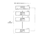
図1は、実施例1である“カラー画像形成装置”の全体構成を示す断面図である。この装置は、図示のように、電子写真方式のカラー画像形成装置の一例である、中間転写体27を採用したタンデム方式のカラー画像形成装置である。本カラー画像形成装置は、図1に示す画像形成部と図示しない画像処理部から構成される。
FIG. 1 is a cross-sectional view illustrating an overall configuration of a “color image forming apparatus” according to a first embodiment. As shown in the figure, this apparatus is a tandem color image forming apparatus employing an
最初に画像処理部における処理について説明する。図2は、本カラー画像形成装置の画像処理部における処理の一例を示すフローチャートである。ステップ131(図ではS131と表記する)で、あらかじめ用意されているカラーマッチングテーブルにより、ホストコンピュータ等から送られてくる画像の色を表すRGB信号をカラー画像形成装置の色再現域に合わせたデバイスRGB信号(以下DevRGBという)に変換する。ステップ132で、あらかじめ用意されている色分解テーブルにより、前記DevRGB信号をカラー画像形成装置のトナー色材色であるCMYK信号に変換する。ステップ133で、各々のカラー画像形成装置に固有の階調−濃度特性を補正する濃度補正テーブルにより、前記CMYK信号を階調−濃度特性の補正を加えたC’M’Y’K’信号へ変換する。その後ステップ134でハーフトーン処理を行いC’’M’’Y’’K’’信号へ変換する。ステップ135で、PWM(Pulse Width Modulation)テーブルにより、前記C’’M’’Y’’K’’信号に対応する前記スキャナ部24C、24M、24Y、24Kの露光時間Tc、Tm、Ty、Tkへ変換する。
First, processing in the image processing unit will be described. FIG. 2 is a flowchart illustrating an example of processing in the image processing unit of the color image forming apparatus. In step 131 (denoted as S131 in the figure), a device that matches an RGB signal representing the color of an image sent from a host computer or the like with the color reproduction range of the color image forming apparatus using a color matching table prepared in advance. It is converted into an RGB signal (hereinafter referred to as DevRGB). In step 132, the DevRGB signal is converted into a CMYK signal, which is the color of the toner color material of the color image forming apparatus, using a color separation table prepared in advance. In step 133, the CMYK signal is converted into a C′M′Y′K ′ signal obtained by correcting the gradation-density characteristic by using a density correction table for correcting the gradation-density characteristic specific to each color image forming apparatus. Convert. Thereafter, in step 134, halftone processing is performed to convert the signal into a C ″ ″ M ″ ″ ″ ″ K ″ signal. In
次に図1を用いて、画像形成部の動作を説明する。画像処理部が変換した露光時間に基づいて点灯させる露光光により静電潜像を形成し、この静電潜像を現像して単色トナー像を形成し、この単色トナー像を重ね合わせて多色トナー像を形成し、この多色トナー像を転写材11へ転写し、その転写材11上の多色トナー像を定着させるもので、画像形成部は給紙部21、現像色分並置したステーション毎の感光体22Y、22M、22C、22K、一次帯電手段としての注入帯電手段23Y、23M、23C、23K、トナーカートリッジ25Y、25M、25C、25K、現像手段26Y、26M、26C、26K、中間転写体27、転写ローラ28および定着部30によって構成されている。
Next, the operation of the image forming unit will be described with reference to FIG. An electrostatic latent image is formed by exposure light that is turned on based on the exposure time converted by the image processing unit, the electrostatic latent image is developed to form a single color toner image, and the single color toner image is superimposed to obtain a multicolor image. A toner image is formed, this multi-color toner image is transferred to a
前記感光ドラム(感光体)22Y、22M、22C、22Kは、アルミシリンダの外周に有機光導伝層を塗布して構成し、図示しない駆動モータの駆動力が伝達されて回転するもので、駆動モータは感光ドラム22Y、22M、22C、22Kを画像形成動作に応じて反時計周り方向に回転させる。
The photosensitive drums (photoconductors) 22Y, 22M, 22C, and 22K are configured by applying an organic optical conductive layer to the outer periphery of an aluminum cylinder, and are rotated by the driving force of a driving motor (not shown) being transmitted. Rotates the
一次帯電手段として、ステーション毎にイエロー(Y)、マゼンダ(M)、シアン(C)、ブラック(K)の感光体を帯電させるための4個の注入帯電器23Y、23M、23C、23Kを備える構成で、各注入帯電器にはスリーブ23YS、23MS、23CS、23KSが備えられている。
As the primary charging means, four
感光ドラム22Y、22M、22C、22Kへの露光光はスキャナ部24Y、24M、24C、24Kから送られ、感光ドラム22Y、22M、22C、22Kの表面を選択的に露光することにより、静電潜像が形成されるように構成されている。
Exposure light to the
現像手段として、前記静電潜像を可視化するために、ステーション毎にイエロー(Y)、マゼンダ(M)、シアン(C)、ブラック(K)の現像を行う4個の現像器26Y、26M、26C、26Kを備える構成で、各現像器には、スリーブ26YS、26MS、26CS、26KSが設けられている。各々の現像器は脱着可能に取り付けられている。
As developing means, in order to visualize the electrostatic latent image, four developing
中間転写体27は、感光ドラム22Y、22M、22C、22Kに接触しており、カラー画像形成時に時計周り方向に回転し、感光ドラム22Y、22M、22C、22Kの回転に伴って回転し、単色トナー像が転写される。その後、中間転写体27に後述する転写ローラ28が接触して転写材11を狭持搬送し、転写材11に中間転写体27上の多色トナー像が転写する。
The
転写ローラ28は、転写材11上に多色トナー像を転写している間、28aの位置で転写材11に当接し、印字処理後は28bの位置に離間する。
The transfer roller 28 contacts the
定着部30は、転写材11を搬送させながら、転写された多色トナー像を溶融定着させるものであり、図1に示すように転写材11を加熱する定着ローラ31と転写材11を定着ローラ31に圧接させるための加圧ローラ32を備えている。定着ローラ31と加圧ローラ32は中空状に形成され、内部にそれぞれヒータ33、34が内蔵されている。すなわち、多色トナー像を保持した転写材11は定着ローラ31と加圧ローラ32により搬送されるとともに、熱および圧力を加えられ、トナーが表面に定着される。
The fixing
トナー像定着後の転写材11は、その後図示しない排出ローラによって図示しない排紙トレイに排出して画像形成動作を終了する。
After the toner image is fixed, the
クリーニング手段29は、中間転写体27上に残ったトナーをクリーニングするものであり、中間転写体27上に形成された4色の多色トナー像を転写材11に転写した後の廃トナーは、クリーナ容器に蓄えられる。
The
濃度センサ41は、図1のカラー画像形成装置において中間転写体27へ向けて配置されており、中間転写体27の表面上に形成されたトナーパッチの濃度を測定する。この濃度センサ41の構成の一例を図3に示す。LEDなどの赤外発光素子51と、フォトダイオード、Cds等の受光素子52、受光データを処理する図示しないICなどとこれらを収容する図示しないホルダーで構成される。受光素子52aはトナーパッチからの乱反射光強度を検知し、受光素子52bはトナーパッチからの正反射光強度を検知する。正反射光強度と乱反射光強度の両方を検知することにより、高濃度から低濃度までのトナーパッチの濃度を検知することができる。また、所定の紙との色差を出力とすることもできる。なお、前記発光素子51と受光素子52の結合のために図示しない光学素子が用いられることもある。
The
前記濃度センサ41は中間転写体27上に乗っているトナーの色を見分けることはできない。そのため、単色トナーの階調パッチ64を中間転写体27上に形成する。その後この濃度データは、画像処理部の階調−濃度特性を補正する濃度補正テーブルや、画像形成部の各プロセス条件へフィードバックされる。
The
カラーセンサ42は、図1のカラー画像形成装置において転写材搬送路の定着部30より下流に転写材11の画像形成面へ向けて配置されており、転写材11上に形成された定着後の混色パッチの色のRGB出力値を検知する。カラーセンサ42は、前記中間転写体27へ向けて配置された図1の濃度センサ41と非常に似ている。
The
図4にカラーセンサ42の構成の一例を示す。カラーセンサ42は、白色LED53とRGBオンチップフィルタ付き電荷蓄積型センサ54aにより構成される。白色LED53を、定着後のパッチが形成された転写材11に対して斜め45度より入射させ、0度方向への乱反射光強度をRGBオンチップフィルタ付き電荷蓄積型センサ54aにより検知する。RGBオンチップフィルタ付き電荷蓄積型センサ54aの受光部は、54bのようにRGBが独立した画素となっている。RGBオンチップフィルタ付き電荷蓄積型センサ54の電荷蓄積型センサは、フォトダイオードでも良い。RGBの3画素のセットが、数セット並んでいるものも有る。また、入射角が0度、反射角が45度の構成でも良い。更には、RGB3色を発光するLEDとフィルタ無しセンサにより構成しても良い。
FIG. 4 shows an example of the configuration of the
次にこれらのセンサを用いた本実施例における階調−濃度特性制御の概念を説明する。図5は、カラーセンサ42と濃度センサ41を組み合わせた階調−濃度特性の制御を示すフローチャートである。カラーセンサを用いた制御は、転写材を消費するため、実施回数が濃度センサを用いた制御に比べて制限される。そこで、図5に示すように、最初にステップ101でカラーセンサと濃度センサを用いた階調−濃度特性制御(以下混色制御という)を実行し、その後ステップ102〜104において濃度センサのみを用いた階調−濃度特性制御(以下単色制御と言う)を規定回数実行し、再び混色制御へ戻る。なお、混色及び単色制御は、通常のプリント動作の合間に実行される。実行のタイミングは、環境変動などを検知しあらかじめ設定された所定のタイミングで自動的に実行するか、又はユーザーが制御実行を所望した場合にユーザーの手動操作により実行される。
Next, the concept of gradation-density characteristic control in this embodiment using these sensors will be described. FIG. 5 is a flowchart showing control of gradation-density characteristics in which the
図6は、前記混色制御と単色制御を組み合わせた階調−濃度特性の制御の詳細を示すフローチャートである。 FIG. 6 is a flowchart showing details of the gradation-density characteristic control combining the color mixture control and the single color control.
まず、新規のカートリッジが使用される場合、すなわちカラー画像形成装置が最初に設置された時、またはカートリッジが交換された時にはステップ111でC,M,Y,K各色の階調−濃度特性のターゲットとしてあらかじめ定められたデフォルトの階調−濃度曲線を用いる。デフォルトの階調−濃度曲線はカラー画像形成装置の特性を加味して設定される。本実施例では図7のような入力階調度に対して出力濃度が線形になるようなものを用いる。また、濃度補正テーブルは入力値を変更しない所謂スルーのテーブルを用いる。 First, when a new cartridge is used, that is, when the color image forming apparatus is first installed, or when the cartridge is replaced, in step 111, the target of gradation-density characteristics of each color of C, M, Y, K A predetermined default gradation-density curve is used. The default gradation-density curve is set in consideration of the characteristics of the color image forming apparatus. In this embodiment, the output density is linear with respect to the input gradation as shown in FIG. The density correction table is a so-called through table that does not change the input value.
次に中間転写体上にパッチパターンを形成し、濃度センサによって読み取る(ステップ112)。図8に、中間転写体上に形成するパッチパターンの例を示す。未定着Kトナー単色の階調パッチ64が並んでおり、この後、図示しないC,M,Yトナー単色の階調パッチが引き続き形成される。この時パッチを形成するC,M,Y,Kの階調度はあらかじめ定められたものを用いる。中間転写体上に形成されたパッチパターンは濃度センサによって濃度を検知され、検知された濃度より補間により階調−濃度曲線が生成される。濃度検知結果が図9の黒丸で示したようになった場合には、例えば線形補間のような補間により100のような階調−濃度曲線を生成する。さらにステップ111で設定されたターゲットの濃度曲線300を基準に逆特性の曲線200を算出し、これを入力画像データに対する濃度補正テーブルとする。入力画像データに対してこの濃度補正テーブルでテーブル変換することにより入力階調度と出力濃度がターゲットの階調−濃度曲線300の関係になる(ステップ113)。
Next, a patch pattern is formed on the intermediate transfer member and read by the density sensor (step 112). FIG. 8 shows an example of a patch pattern formed on the intermediate transfer member. Unfixed K toner single-
ステップ114ではステップ113で生成された濃度補正テーブル200を用いてCMY混色パッチ及びKの単色パッチパターンを転写材上に形成し、カラーセンサで検知する。以下本ステップの内容を詳細に述べる。
In
CMY混色パッチおよびK単色パッチの各パッチ(1)〜(9)は、図10のようなC,M,Yのデータ(1)〜(8)及びKの単色データ(9)からなっている。各パッチのC,M,Yの階調度は基準の階調度(以下、基準値と記す)C0,M0,Y0から階調度を±α変化させた値の組み合わせになっている。また(9)のパッチはKの単色パッチで、あらかじめ定められた階調度K0で形成される。ここでC0,M0,Y0,K0の値は、C,M,Y,Kの階調−濃度特性がデフォルトの階調−濃度曲線300の状態に調整され、通常の画像形成条件下で、C0,M0,Y0の値を混色するとK0と同じ色になるような値であり、色処理及びハーフトーン設計時に設定される。転写材上には図11のように(1)〜(9)のパッチパターンが形成され、転写材上に形成されたパッチは定着装置30通過後、カラーセンサ42で検知し、RGB値を出力する。
Each of the patches (1) to (9) of the CMY mixed color patch and the K single color patch includes C, M, Y data (1) to (8) and K single color data (9) as shown in FIG. . The gradation of C, M, and Y of each patch is a combination of values obtained by changing the gradation by ± α from reference gradations (hereinafter referred to as reference values) C0, M0, and Y0. The patch (9) is a K single color patch, which is formed with a predetermined gradation K0. Here, the values of C0, M0, Y0, and K0 are adjusted so that the gradation-density characteristics of C, M, Y, and K are adjusted to the state of the default gradation-
次にステップ115でセンサのRGB出力値からC,M,Yのプロセスグレーと(9)のKのパッチの色が一致するためのC,M,Yの値(階調度)を算出する。 Next, in step 115, C, M, and Y values (gradation levels) for matching the C, M, and Y process grays with the K patch color in (9) are calculated from the RGB output values of the sensor.
画像形成条件が色処理設計時と全く同じ状態であればK0の色は(C0,M0,Y0)を混色した色と一致するが、従来の技術で述べたような理由で一致せず、色がずれてしまう。各パッチのRGB出力値を(1)=(r1、g1、b1),(2)=(r2、g2、b2),…とし、(1)〜(8)の各パッチのC,M,Y座標を3次元的に表すと図12のようになる。図の立方格子の中心の座標は(C0,M0,Y0)となる。 If the image formation conditions are exactly the same as those at the time of color processing design, the color of K0 matches the color mixed with (C0, M0, Y0), but it does not match for the reason described in the prior art, and the color Will shift. The RGB output values of each patch are (1) = (r1, g1, b1), (2) = (r2, g2, b2),..., And C, M, Y of each patch of (1) to (8) FIG. 12 shows the coordinates three-dimensionally. The coordinates of the center of the cubic lattice in the figure are (C0, M0, Y0).
(1)〜(8)のRGB値からK0のRGB値と一致するためのC,M,Yの値を図12から8点の線形補間によって求める。具体的には図12の立方格子内の各C,M,Yの座標に対するRGB値(Rcmy,Gcmy,Bcmy)を下記の式で計算することによって求める。
Rcmy=[(C−C0+α)(M−M0+α)(Y−Y0+α)r1+
(C0+α−C)(M−M0+α)(Y−Y0+α)r2+
(C−C0+α)(M0+α−M)(Y−Y0+α)r3+
(C−C0+α)(M−M0+α)(Y0+α−Y)r4+
(C0+α−C)(M0+α−M)(Y−Y0+α)r5+
(C0+α−C)(M−M0+α)(Y0+α−Y)r6+
(C−C0+α)(M0+α−M)(Y0+α−Y)r7+
(C0+α−C)(M0+α−M)(Y0+α−Y)r8]/(8α3)
Gcmy,Bcmyも同様の式で求める。
From the RGB values of (1) to (8), C, M, and Y values for matching with the RGB value of K0 are obtained by linear interpolation of 8 points from FIG. Specifically, the RGB values (Rcmy, Gcmy, Bcmy) for the coordinates of C, M, and Y in the cubic lattice of FIG. 12 are calculated by the following formula.
Rcmy = [(C−C0 + α) (M−M0 + α) (Y−Y0 + α) r1 +
(C0 + α-C) (M-M0 + α) (Y-Y0 + α) r2 +
(C−C0 + α) (M0 + α−M) (Y−Y0 + α) r3 +
(C−C0 + α) (M−M0 + α) (Y0 + α−Y) r4 +
(C0 + α-C) (M0 + α-M) (Y-Y0 + α) r5 +
(C0 + α-C) (M-M0 + α) (Y0 + α-Y) r6 +
(C−C0 + α) (M0 + α−M) (Y0 + α−Y) r7 +
(C0 + α-C) ( M0 + α-M) (Y0 + α-Y) r8] / (8α 3)
Gcmy and Bcmy are also obtained by the same formula.
上式で計算された(Rcmy,Gcmy,Bcmy)とKのRGB値(Rk,Gk,Bk)の差を例えば各RGBの差分の2乗和などで求める。そして差の最も小さいもの、すなわち最も(Rk,Gk,Bk)に近い(Rcmy,Gcmy,Bcmy)を求め、この時のC,M,Yの値を最適値とし(C0’,M0’,Y0’)とする。 The difference between (Rcmy, Gcmy, Bcmy) calculated by the above formula and the RGB value (Rk, Gk, Bk) of K is obtained by, for example, the sum of squares of the differences of each RGB. Then, the one having the smallest difference, that is, (Rcmy, Gcmy, Bcmy) closest to (Rk, Gk, Bk) is obtained, and the values of C, M, Y at this time are set as optimum values (C0 ′, M0 ′, Y0). ').
なお、αは補間の精度を上げるためには立方格子の大きさはできるだけ小さいことが望ましい。 Note that α is preferably as small as possible in order to increase the accuracy of interpolation.
K0と(C0,M0,Y0)の色が大きくずれている場合、(C0’,M0’,Y0’)は立方格子の中心(C0,M0,Y0)の近傍にはないが、この場合でも(C0’,M0’,Y0’)は立方格子内に入っていなければならないため、立方格子はそれに十分な大きさである必要がある。この2つの条件を加味し、最適な値に設定する。 When the colors of K0 and (C0, M0, Y0) are greatly shifted, (C0 ′, M0 ′, Y0 ′) is not near the center (C0, M0, Y0) of the cubic lattice. Since (C0 ′, M0 ′, Y0 ′) must be in the cubic lattice, the cubic lattice needs to be large enough for it. Considering these two conditions, the optimum value is set.
さらにKの階調度を変化させて、複数の基準値(CN,MN,YN,KN)(N=0,1,2…n)を持ち、各基準値に対して前記と同様の(1)〜(9)のパッチを形成し、各(CN,MN,YN,KN)に対して(CN’,MN’,YN’,KN’)を求める。このようにして求めた(CN,MN,YN)と(CN’,MN’,YN’)のシアンの関係が図13の黒丸のようになったとすると、間の値を例えば線形補間して150のような曲線(色補正テーブル)を作る。 Further, the gradation of K is changed to have a plurality of reference values (CN, MN, YN, KN) (N = 0, 1, 2,... N), and (1) as described above for each reference value. The patches (9) to (9) are formed, and (CN ′, MN ′, YN ′, KN ′) is obtained for each (CN, MN, YN, KN). If the relationship between cyan (CN, MN, YN) and (CN ′, MN ′, YN ′) obtained in this way is as shown by the black circles in FIG. Create a curve (color correction table) like
次にステップ116で濃度補正のターゲットテーブルを補正する。元のターゲット階調−濃度曲線(図9、300)に対して図13の色補正テーブル150を掛け合わせた階調−濃度曲線を生成し、これを新しいシアンのターゲットの階調−濃度曲線とする(図14、400)。具体的には入力階調度に対して色補正テーブル150でテーブル変換した後にターゲット階調−濃度曲線にしたがって出力濃度に変換する。 In step 116, the density correction target table is corrected. A tone-density curve is generated by multiplying the original target tone-density curve (FIGS. 9 and 300) by the color correction table 150 of FIG. 13, and this is used as a new cyan target tone-density curve. (FIG. 14, 400). Specifically, the input gradation degree is converted into the output density according to the target gradation-density curve after table conversion by the color correction table 150.
同様にM,Yについてもターゲットを変更する。この新しいターゲットで濃度補正を行うことで、(CN,MN,YN)の混色による色はKNの色と一致する。 Similarly, the targets for M and Y are changed. By performing density correction with this new target, the color due to the color mixture of (CN, MN, YN) matches the color of KN.
なお、(CN,MN,YN,KN)の値は“人間の目はハイライトのグレーに敏感で、シャドウになるほど鈍感になること”、“通常色処理時にはUCR処理(色分解時にCMYの一部をKで置き換える処理)を行うため、シャドウ領域ではCMYの3色のみによるグレーは現われないこと”に留意して、ハイライトを中心に選ぶことによって本発明をより効果的に実施できる。 It should be noted that the values of (CN, MN, YN, KN) are “the human eye is sensitive to highlight gray and becomes insensitive as shadows occur”, “UCR processing during normal color processing (one of CMY during color separation) In consideration of the fact that only the three colors of CMY do not appear in the shadow area, the present invention can be implemented more effectively by focusing on highlights.
ステップ117で、ステップ112の濃度検知結果からステップ116で変更されたC,M,Yのターゲットを用いて改めて濃度補正テーブルを生成し、以後プリント時にはこの濃度補正テーブルを用いて入力画像データの濃度補正を行い、通常プリント状態に入る(ステップ118)。 In step 117, a density correction table is generated again using the C, M, and Y targets changed in step 116 from the density detection result in step 112, and the density of the input image data is used by using this density correction table for printing thereafter. Correction is performed and the normal printing state is entered (step 118).
通常プリント状態で規程枚数プリントすると(ステップ120)、単色濃度制御を行う。単色濃度制御ではステップ121でステップ112と同様に中間転写体上にパッチパターンを形成し、濃度センサによって読み取る。中間転写体上に形成されたパッチパターンは濃度センサによって濃度を検知され、検知された濃度より補間により階調−濃度曲線を生成し、ステップ116で生成されたターゲット400を用いてステップ113と同様の手法で濃度補正テーブルを更新する(ステップ122)。さらに規程回数単色濃度制御が行われたかどうか判断し(ステップ123)、規程回数に達していない場合には再び通常プリントに入る。規程回数行われていれば、再度ステップ114でCMY混色及びKの単色パッチパターンを転写材上に形成し、カラーセンサで検知する。この時パッチパターンの形成は最新の濃度補正テーブルを用いて行う。その後は前述したステップで処理が行われる。ただし、新しいターゲット作成時には前回のステップ116で生成されたターゲット400に対して新しい逆特性テーブルを掛け合わせる。
When the specified number of sheets is printed in the normal printing state (step 120), monochrome density control is performed. In monochromatic density control, a patch pattern is formed on the intermediate transfer member in step 121 as in step 112, and is read by a density sensor. The density of the patch pattern formed on the intermediate transfer member is detected by a density sensor, a tone-density curve is generated by interpolation from the detected density, and the
また、通常プリント状態でいずれかの色のカートリッジが交換された場合(ステップ119)には画像形成条件が大きく変わるため、再びステップ111の処理へと戻る。 Further, when any color cartridge is replaced in the normal printing state (step 119), the image forming conditions greatly change, so the processing returns to step 111 again.
なお、本実施例では精度を重視して前記のようにターゲットを補正する構成をとったが、ターゲットは補正せずに濃度補正テーブルの後に図13,150の補正テーブルを掛け合わせる構成をとってもよい。 In the present embodiment, the target is corrected as described above with emphasis on accuracy. However, the target may not be corrected, and the density correction table may be multiplied by the correction table shown in FIGS. .
また、本実施例では最適なC,M,Yの値を算出するのに3次元の線形補間を用いたが、補間の手法としては2次関数近似や3次関数近似、あるいはスプライン補間のような非線形な手法を用いてもよい。 In this embodiment, three-dimensional linear interpolation is used to calculate the optimum C, M, and Y values. As an interpolation method, quadratic function approximation, cubic function approximation, or spline interpolation is used. A non-linear method may be used.
また、本実施例ではαの値はC,M,Yで同一のものを用いたが、色毎に異なる値を用いてもよい。 In this embodiment, the same α, C, M, and Y values are used. However, different values may be used for each color.
さらに、本実施例ではカラーセンサはRGB出力としたが、L*a*b*やL*c*h*、XYZ等の色度を出力するものでもよい。 Furthermore, in this embodiment, the color sensor is RGB output, but it may output chromaticity such as L * a * b *, L * c * h *, and XYZ.
さらに、本実施例ではC,M,Yの混色パッチの色をKのパッチの色に合わせたが、カラーセンサでC,M,Yの混色パッチのL*a*b*値等を測定し、例えばa=0,b=0の無彩色軸をターゲットにしてC,M,Yの混色が無彩色となる最適な階調度を算出し、単色制御にフィードバックしてもよい。 Further, in this embodiment, the color of the mixed color patch of C, M, and Y is matched to the color of the patch of K. However, the L * a * b * value of the mixed color patch of C, M, and Y is measured by the color sensor. For example, an optimum gradation degree at which the mixed color of C, M, and Y becomes an achromatic color may be calculated by targeting the achromatic axis of a = 0 and b = 0, and may be fed back to the monochromatic control.
実施例2の“カラー画像形成装置”の構成は実施例1と同様とする。本実施例でのフローチャートを図15に示す。 The configuration of the “color image forming apparatus” of the second embodiment is the same as that of the first embodiment. A flowchart in this embodiment is shown in FIG.
まず、新規のカートリッジが使用される場合、すなわちカラー画像形成装置が最初に設置された時、またはカートリッジが交換された時にはステップ211でKの階調−濃度特性のターゲットとしてあらかじめ定められた階調−濃度曲線を用いる。デフォルトの階調−濃度曲線はカラー画像形成装置の特性を加味して設定される。本実施例では図7のような入力階調度に対して出力濃度が線形になるようなものを用いる。また、濃度補正テーブル133は入力値を変更しない所謂スルーのテーブルを用いる。
First, when a new cartridge is used, that is, when the color image forming apparatus is first installed, or when the cartridge is replaced, the gradation determined in advance as the target of the K gradation-density characteristic in
次に中間転写体上にパッチパターンを形成し、濃度センサによって読み取る(ステップ212)。中間転写体上に形成するパッチパターンは実施例1,図8と同様であるが、本実施例では未定着Kトナー単色の階調パッチ64のみが並ぶ。この時パッチを形成するKの階調度はあらかじめ定められたものを用いる。中間転写体上に形成されたパッチパターンは濃度センサによって濃度を検知され、検知された濃度より補間により階調−濃度曲線が生成される。濃度検知結果が図9の黒丸で示したようになった場合には、例えば線形補間のような補間により100のような階調−濃度曲線を生成する。さらにターゲットの濃度曲線を基準に逆特性の曲線200を算出し、これを入力画像データに対する濃度補正テーブルとする。入力画像データに対してこの濃度補正テーブルでテーブル変換することにより入力データと出力濃度がターゲットの階調−濃度曲線300の関係になる(ステップ213)。
Next, a patch pattern is formed on the intermediate transfer member and read by the density sensor (step 212). The patch pattern formed on the intermediate transfer member is the same as that of the first embodiment and FIG. 8, but in this embodiment, only the unfixed K toner single-
次にステップ214であらかじめ定められているデフォルト値(Cd,Md,Yd)を次の混色制御のパッチの基準値(C0,M0,Y0)としてセットする。 Next, in step 214, a predetermined default value (Cd, Md, Yd) is set as a reference value (C0, M0, Y0) for the next color mixture control patch.
ステップ215ではKについてはステップ213で生成された濃度補正テーブル300を用いて、C,M,Yについてはスルーのテーブルを用いて、CMY混色及びKの単色パッチパターンを転写材上に形成し、カラーセンサで検知する。以下本ステップの内容を詳細に述べる。 In step 215, a KMY mixed color and K single-color patch pattern is formed on the transfer material using the density correction table 300 generated in step 213 for K, and a through table for C, M, and Y. Detect with color sensor. The details of this step will be described below.
CMY混色パッチおよびKの単色パッチの各パッチは図16のようなC,M,Yのデータ(1)〜(6)及びKの単色データ(7)からなっている。本実施例では各パッチのC,M,Yの値は基準値C0,M0,Y0から特定の色のみを±α変化させた値となっている。また(7)のパッチはKの単色パッチで、あらかじめ定められた値K0で形成される。前述のように最初はC0,M0,Y0にはデフォルト値(Cd,Md,Yd)がセットされている。(Cd,Md,Yd)はKの濃度特性が階調−濃度曲線300の状態に調整され、C,M,Yが典型的な階調−濃度曲線の状態でCd,Md,Ydの値を混色するとK0とほぼ同じ色となるような値である。転写材上には図17のように(1)〜(7)のパッチパターンが形成され、転写材上に形成されたパッチは定着装置30通過後、カラーセンサ42で検知し、RGB値を出力する(ステップ215)。
Each patch of the CMY mixed color patch and the K single color patch includes C, M, Y data (1) to (6) and K single color data (7) as shown in FIG. In this embodiment, the values of C, M, and Y of each patch are values obtained by changing only a specific color by ± α from the reference values C0, M0, and Y0. The patch (7) is a K single-color patch and is formed with a predetermined value K0. As described above, default values (Cd, Md, Yd) are initially set in C0, M0, Y0. (Cd, Md, Yd) is a state in which the density characteristic of K is adjusted to the state of the gradation-
次にステップ216でセンサのRGB出力値からC,M,YのプロセスグレーとKの色が一致するためのC,M,Yの値(階調度)を算出する。
In
画像形成条件が色処理設計時と全く同じ状態であればK0の色は(C0,M0,Y0)を混色した色と一致するが、従来の技術で述べたような理由で一致せず、色がずれてしまう。各パッチのRGB出力値を(1)=(r1、g1、b1),(2)=(r2、g2、b2),…とし、(1)〜(8)の各パッチのC,M,Y座標を3次元的に表すと図18のようになる。図の3つの軸の交点の座標は(C0,M0,Y0)となる。 If the image formation conditions are exactly the same as those at the time of color processing design, the color of K0 matches the color mixed with (C0, M0, Y0), but it does not match for the reason described in the prior art, and the color Will shift. The RGB output values of each patch are (1) = (r1, g1, b1), (2) = (r2, g2, b2),..., And C, M, Y of each patch of (1) to (8) FIG. 18 shows the coordinates in a three-dimensional manner. The coordinates of the intersection of the three axes in the figure are (C0, M0, Y0).
(1)〜(6)のRGB値からK0のRGB値と一致するためのC,M,Yの値を図18から求める。具体的にはまず(1)(2)間の軸上でCの値を変化させて各Cの値(Rc,Gc,Bc)を下式で線形補間によって求める。
Rc=[(C−C0+α)r1+(C0+α−C)r2 ]/(2α)
Gc=[(C−C0+α)g1+(C0+α−C)g2 ]/(2α)
Bc=[(C−C0+α)b1+(C0+α−C)g2 ]/(2α)
上式で計算された(Rc,Gc,Bc)とKのRGB値(Rk,Gk,Bk)の差を例えば各RGBの差分の2乗和などで求める。そして差の最も小さいもの、すなわち最も(Rk,Gk,Bk)に近い(Rc,Gc,Bc)を求め、この時のCの値を最適値としC0’とする。
From the RGB values of (1) to (6), C, M, and Y values for matching with the RGB value of K0 are obtained from FIG. Specifically, first, the value of C is changed on the axis between (1) and (2), and the value of each C (Rc, Gc, Bc) is obtained by linear interpolation using the following equation.
Rc = [(C−C0 + α) r1 + (C0 + α−C) r2] / (2α)
Gc = [(C−C0 + α) g1 + (C0 + α−C) g2] / (2α)
Bc = [(C−C0 + α) b1 + (C0 + α−C) g2] / (2α)
The difference between (Rc, Gc, Bc) calculated by the above formula and the RGB value (Rk, Gk, Bk) of K is obtained by, for example, the sum of squares of the differences of RGB. Then, the one with the smallest difference, that is, (Rc, Gc, Bc) closest to (Rk, Gk, Bk) is obtained, and the value of C at this time is set as the optimum value and is set as C0 ′.
M,Yについても同様に最適値M0’,Y0’を求め、(C0’,M0’,Y0’)を最もK0に近い色を形成するC,M,Yの最適値とする。 Similarly, optimum values M0 'and Y0' are obtained for M and Y, and (C0 ', M0', Y0 ') are set as the optimum values of C, M, and Y that form a color closest to K0.
その後の流れは実施例1のフローチャート図6と同様であるが、本実施例では単色制御が規程回数行われると(ステップ224)、ステップ225で前回の混色制御で求めた最適値(C0’,M0’,Y0’)を基準値(C0,M0,Y0)にセットする。そして新たな基準値(C0,M0,Y0)でパッチを形成し、カラーセンサで検知する(ステップ215)。 The subsequent flow is the same as that of the flowchart of FIG. 6 of the first embodiment. However, in this embodiment, when the single color control is performed a predetermined number of times (step 224), the optimum value (C0 ′, M0 ′, Y0 ′) is set to the reference value (C0, M0, Y0). Then, a patch is formed with a new reference value (C0, M0, Y0) and detected by the color sensor (step 215).
通常プリント状態でいずれかの色のカートリッジが交換された場合(ステップ220)は再びステップ211の処理へと戻り、Kの濃度制御が行われた後に再びデフォルトの基準値(Cd,Md,Yd)で混色制御が行われる。
When the cartridge of any color is replaced in the normal printing state (step 220), the process returns to the process of
以上、本実施例では混色パッチ1組の組み合わせの数が7つと少なく、パッチの組をより多く転写材上に形成することができる。また、基準値として前回の最適値を用いることによってより精度の高い制御をすることが可能である。 As described above, in this embodiment, the number of combinations of one set of mixed color patches is as small as seven, and a larger number of sets of patches can be formed on the transfer material. Further, it is possible to perform control with higher accuracy by using the previous optimum value as the reference value.
なお、本実施例でも実施例1と同様、αの値はC,M,Yで同一のものを用いたが、色毎に異なる値を用いてもよい。 In this embodiment, as in the first embodiment, the same α value is used for C, M, and Y, but different values may be used for each color.
実施例3の“カラー画像形成装置”の構成は実施例1と同様とする。 The configuration of the “color image forming apparatus” of the third embodiment is the same as that of the first embodiment.
実施例1,2では混色制御用のパッチを1回しか形成していないが、本実施例では複数回パッチパターンを形成することが特徴である。 In the first and second embodiments, the patch for color mixture control is formed only once, but this embodiment is characterized in that the patch pattern is formed a plurality of times.
本実施例での処理の流れは混色制御以外の部分は、実施例1における図6のフローチャートと同じである。本実施例における混色制御のフローチャートを図19に示す。 The processing flow in the present embodiment is the same as the flowchart of FIG. 6 in the first embodiment except for the color mixture control. FIG. 19 shows a flowchart of color mixture control in this embodiment.
ステップ311で混色制御が開始されると、あらかじめ定められているC,M,Yの階調度(C0,M0,Y0)が初期値として基準値(Cs,Ms,Ys)にセットされる(ステップ312)。ただし、(C0,M0,Y0)は実施例1と同様にして定められた値である。さらにステップ313で初期値α0をαにセットする。また、C,M,Y,Kの濃度補正テーブルは不図示の単色制御によって濃度制御されたものを用いる。 When color mixing control is started in step 311, predetermined gradation levels (C0, M0, Y0) of C, M, and Y are set to reference values (Cs, Ms, Ys) as initial values (steps). 312). However, (C0, M0, Y0) is a value determined in the same manner as in the first embodiment. In step 313, the initial value α0 is set to α. The density correction table for C, M, Y, and K uses a density controlled by monochromatic control (not shown).
ステップ314ではCMY混色及びKの単色パッチパターンが形成される。図20に本実施例におけるパッチパターンの内容を示す。 In step 314, a CMY mixed color and K single-color patch pattern is formed. FIG. 20 shows the contents of the patch pattern in this embodiment.
各パッチのC,M,Yの値は基準値Cs,Ms,Ysから±α変化させた値の組み合わせになっている。また(9)のパッチはKの単色パッチで、あらかじめ定められた値K0で形成される。転写材上には実施例1と同様、図11のように(1)〜(9)のパッチパターンが形成され、転写材上に形成されたパッチは定着装置30通過後、カラーセンサ42で検知し、RGB値を出力する。
The values of C, M, and Y of each patch are a combination of values obtained by changing ± α from the reference values Cs, Ms, and Ys. The patch (9) is a K single-color patch and is formed with a predetermined value K0. As in the first embodiment, patch patterns (1) to (9) are formed on the transfer material as shown in FIG. 11, and the patches formed on the transfer material are detected by the
次にステップ315で実施例1と同様の手法で最適値(C0’,M0’,Y0’)を求める。 Next, in step 315, optimum values (C0 ', M0', Y0 ') are obtained by the same method as in the first embodiment.
ステップ316ではステップ315で求めた(C0’,M0’,Y0’)を用いて再び転写材上にパッチを形成する。この時、同時にK0の単色パッチも形成する。転写材上に形成されたパッチは定着装置30通過後、カラーセンサ42で検知し、RGB値を出力する。
In step 316, a patch is formed again on the transfer material using (C0 ', M0', Y0 ') obtained in step 315. At this time, a K0 monochrome patch is also formed. The patch formed on the transfer material is detected by the
ステップ317ではステップ316で出力された(C0’,M0’,Y0’)の混色パッチ,及びK0の単色パッチのRGB値の差分を例えばR,G,Bの差分の2乗和で計算し、ステップ318で前記差分があらかじめ定められているしきい値よりも大きいかどうかを判断する。大きい場合には差分が許容範囲を超えているとし、ステップ319へ進む。
In
ステップ319ではステップ315で算出した(C0’,M0’,Y0’)を基準値(Cs,Ms,Ys)にセットし、ステップ320でαの値を前回のステップ314〜315で使用したαの値の1/2の値にセットし、再びステップ314で新しい基準値とαの値でCMY混色及びKの単色パッチパターンを形成し、カラーセンサでRGB値を検知する。
In
以上のステップ314〜320を基準値(Cs,Ms,Ys)とαを更新しながらステップ318で差分が許容範囲内になるまで繰り返す。 The above steps 314 to 320 are repeated until the difference is within the allowable range in step 318 while updating the reference value (Cs, Ms, Ys) and α.
ステップ314〜320の処理において最適値を探索する概念図を図21に示す。図21では簡単のため、Yの座標を省略し、C,Mの座標で表している。図は横軸がC、縦軸がMであり、初期値としてセットされる(C0,M0)の座標は411aに位置する。混色制御が開始されると最初に(C0,M0)を中心にC,M方向に±α0の範囲の矩形(411b)の4つの角にパッチが形成され(ステップ312〜314)、各パッチの値からの補間によってセンサ出力値が最もK0に近いC,Mの座標(C0’,M0’)(412a)が算出される(ステップ315)。次にステップ316〜317で(C0’,M0’)及びK0のパッチを形成し、センサ出力値の差分が許容範囲内であるかどうかを判断する(ステップ318)。許容範囲内でなければ、次に412aの座標を中心に±α0/2の矩形(412b)の4つの角に第2のパッチが形成され(ステップ319〜314)、再び各パッチの値からの補間によってセンサ出力値が最もK0に近いC,Mの座標(C0’’,M0’’)(413a)が算出される(ステップ315)。
FIG. 21 is a conceptual diagram for searching for the optimum value in the processing of steps 314 to 320. In FIG. 21, for simplicity, the Y coordinate is omitted, and the C and M coordinates are used. In the figure, the horizontal axis is C, the vertical axis is M, and the coordinates of (C0, M0) set as initial values are located at 411a. When color mixing control is started, patches are first formed at four corners of a rectangle (411b) in the range of ± α0 in the C and M directions centering on (C0, M0) (steps 312 to 314). By interpolation from the values, the C and M coordinates (C0 ′, M0 ′) (412a) whose sensor output values are closest to K0 are calculated (step 315). Next, in steps 316 to 317, patches of (C0 ', M0') and K0 are formed, and it is determined whether or not the difference between the sensor output values is within an allowable range (step 318). If it is not within the allowable range, the second patch is formed at the four corners of the rectangle (412b) of ± α0 / 2 around the coordinates of 412a (
次に前述と同様にステップ316〜317で(C0’’,M0’’)及びK0のパッチを形成し、センサ出力値の差分が許容範囲内であるかどうかを判断する(ステップ318)。許容範囲内でなければ、次に413aの座標を中心に±α0/4の矩形(413b)の4つの角に第3のパッチが形成され(ステップ319〜314)、各パッチの値からの補間によってセンサ出力値が最もK0に近い不図示のC,Mの座標(C0’’’,M0’’’)が算出される(ステップ315)。
Next, in the same manner as described above, patches of (C0 ″, M0 ″) and K0 are formed in steps 316 to 317, and it is determined whether the difference between the sensor output values is within an allowable range (step 318). If not within the allowable range, a third patch is formed at four corners of a rectangle (413b) of ± α0 / 4 around the coordinates of 413a (
前述の処理を繰り返すことにより探索範囲を狭めながらC,M,Yの最適値を求めていく。 The optimum values of C, M, and Y are obtained while narrowing the search range by repeating the above processing.
ステップ318で差分がしきい値よりも小さい場合には差分が許容範囲内であるとして、ステップ315で求めたC,M,Yの値を最適値とする。ステップ321〜322は実施例1ステップ116〜117と同様の処理を行う。 If the difference is smaller than the threshold value in step 318, it is determined that the difference is within the allowable range, and the values of C, M, and Y obtained in step 315 are set as optimum values. Steps 321 to 322 perform the same processing as steps 116 to 117 in the first embodiment.
なお、前述では(Cs,Ms,Ys)を1組のみで行ったが、実施例1と同様、複数のKの値KN(N=0,…n)に対する(CN,MN,YN)のパッチを形成し、ステップ318で許容範囲内でない(CN,MN,YN)のパッチについてのみステップ314〜320のループを繰り返してもよい。 In the above description, (Cs, Ms, Ys) is performed by only one set. As in the first embodiment, a patch of (CN, MN, YN) for a plurality of K values KN (N = 0,... N). And the loop of steps 314 to 320 may be repeated only for patches (CN, MN, YN) that are not within the allowable range in step 318.
また、転写材の消費を抑え、パッチの形成回数を減らすために、ステップ316で混色パッチを形成する時に、ステップ318でNOとなる場合を想定してあらかじめ次のステップ314の混色パッチを同時に形成してもよい。 Further, in order to reduce the consumption of the transfer material and reduce the number of patch formations, when the mixed color patch is formed in step 316, the mixed color patch in the next step 314 is formed in advance at the same time assuming the case of NO in step 318. May be.
実施例4の“カラー画像形成装置”の構成は実施例1と同様とする。本実施例での処理の流れは実施例1のフローチャート図6と同じである。本実施例ではステップ115で最適値を求めるのに重回帰分析を用いる。以下、本実施例における最適値の求め方について説明する。 The configuration of the “color image forming apparatus” of the fourth embodiment is the same as that of the first embodiment. The processing flow in the present embodiment is the same as the flowchart in FIG. 6 of the first embodiment. In this embodiment, multiple regression analysis is used to determine the optimum value in step 115. Hereinafter, a method for obtaining the optimum value in the present embodiment will be described.
まず、ステップ114で形成するパッチパターンについて述べる。
First, the patch pattern formed in
CMY混色パッチおよびKの単色パッチの各パッチは図22のようなC,M,Yのデータ(1)〜(6)及びKの単色データ(7)からなっている。C00〜C05、M00〜M05、Y00〜Y05の値は例えば実施例2のように基準値C0,M0,Y0から特定の色のみを±α変化させた値とする。また(7)のパッチはKの単色パッチで、あらかじめ定められた値K0で形成される。基準値(C0,M0,Y0)は実施例2と同様、Kの濃度特性が階調−濃度曲線300の状態に調整され、C,M,Yが典型的な階調−濃度曲線の状態でC0,M0,Y0の値を混色するとK0とほぼ同じ色となるような値である。転写材上には図17のように(1)〜(7)のパッチパターンが形成され、転写材上に形成されたパッチは定着装置30通過後、カラーセンサ42で検知し、RGB値を出力する。
Each patch of the CMY mixed color patch and the K single color patch includes C, M, Y data (1) to (6) and K single color data (7) as shown in FIG. The values of C00 to C05, M00 to M05, and Y00 to Y05 are values obtained by changing only a specific color by ± α from the reference values C0, M0, and Y0 as in the second embodiment. The patch (7) is a K single-color patch and is formed with a predetermined value K0. As in the second embodiment, the reference values (C0, M0, Y0) are adjusted such that the K density characteristic is adjusted to the state of the gradation-
次にステップ115でセンサのRGB出力値からC,M,Yのプロセスグレーと(7)のKのパッチの色が一致するためのC,M,Yの値(階調度)を算出する。 Next, in step 115, C, M, and Y values (gradation levels) for matching the C, M, and Y process grays with the K patch color in (7) are calculated from the RGB output values of the sensor.
各パッチのRGB出力値を(1)=(r00、g00、b00),(2)=(r01、g01、b01),…(6)=(r05、g05、b05)とし、(7)のK単色パッチのRGB出力値を(rk0、gk0、bk0)とする。 The RGB output values of each patch are (1) = (r00, g00, b00), (2) = (r01, g01, b01),... (6) = (r05, g05, b05), and K in (7) The RGB output value of the single color patch is (rk0, gk0, bk0).
ここで、Rについて図23のようにC,M,Yの階調度を説明変量、Rを目的変量として以下の重回帰式の係数rc0、rc1、rc2、rc3を求める。
R=rc1×C+rc2×M+rc3×Y+rc0
係数rc0、rc1、rc2、rc3は以下のようにして求める。
Here, as shown in FIG. 23, the following regression coefficients rc0, rc1, rc2, and rc3 are obtained for R with the gradations of C, M, and Y as explanatory variables and R as a target variable.
R = rc1 * C + rc2 * M + rc3 * Y + rc0
The coefficients rc0, rc1, rc2, and rc3 are obtained as follows.

ただし、 However,
とすると、 Then,
でrc0が求まる。
さらに、G,Bに対しても同様に下記の重回帰式の係数が求まる。
G=gc1×C+gc2×M+gc3×Y+gc0
B=bc1×C+bc2×M+bc3×Y+bc0
ここで、Kの出力値(rk0、gk0、bk0)に対するC,M,Yの値を(C0’,M0’,Y0’)として前記の式に代入し、これを行列で書くと、
To find rc0.
Further, the coefficients of the following multiple regression equations are similarly obtained for G and B.
G = gc1 * C + gc2 * M + gc3 * Y + gc0
B = bc1 * C + bc2 * M + bc3 * Y + bc0
Here, the values of C, M, and Y for the output values of K (rk0, gk0, bk0) are substituted into the above equation as (C0 ′, M0 ′, Y0 ′), and this is written in a matrix.
によって(C0’,M0’,Y0’)が求まる。 (C0 ', M0', Y0 ') is obtained by
さらにKの階調度を変化させて、複数の基準値(CN,MN,YN,KN)(N=0,1,2…n)を持ち、各基準値に対して前記と同様の(1)〜(7)のパッチを形成し、各(CN,MN,YN,KN)に対して(CN’,MN’,YN’,KN’)を求める。 Further, the gradation of K is changed to have a plurality of reference values (CN, MN, YN, KN) (N = 0, 1, 2,... N), and (1) as described above for each reference value. The patches (7) to (7) are formed, and (CN ′, MN ′, YN ′, KN ′) is obtained for each (CN, MN, YN, KN).
その後の処理は図6のステップ116以降と同様である。 The subsequent processing is the same as that after step 116 in FIG.
なお、本実施例ではパッチの数、およびパッチの値を実施例2と同様としたが、パッチの数やその値の選び方はこれに限らない。また、本実施例の特徴としては本実施例では実施例1〜3(図12)のような格子を仮定しないため、パッチの数やパッチの値を比較的自由に選択することができ、基準値とパッチの値の関係に左右されずに精度良く最適値を求めることができる。 In the present embodiment, the number of patches and the patch value are the same as in the second embodiment, but the number of patches and how to select the value are not limited to this. Further, as a feature of the present embodiment, the present embodiment does not assume the lattice as in the first to third embodiments (FIG. 12), so the number of patches and the value of the patches can be selected relatively freely. The optimum value can be obtained with high accuracy regardless of the relationship between the value and the value of the patch.
11 転写材
22 感光体、感光ドラム
26 現像手段
27 中間転写体
41 濃度センサ
42 カラーセンサ
11 Transfer material 22 Photoconductor, photosensitive drum 26 Developing means 27
Claims (6)
前記形成された前記複数の混色パッチと前記単色パッチとを用紙上で定着する定着手段と、
排紙前の用紙上における前記定着された前記複数の混色パッチ及び前記単色パッチの色値を検知可能に配置されており、前記排紙前の用紙上から前記複数の混色パッチの色値と前記単色パッチとの色値を検知する検知手段と、
前記検知手段により検知された前記複数の混色パッチの色値と前記単色パッチの色値とを比較し、該比較に基づき前記単色パッチの色値に近い前記各カラー色材における各色の階調値の組み合わせを求め、画像形成条件を補正する補正手段と、
を備えることを特徴とするカラー画像形成装置。 Image forming means for forming a plurality of mixed color patches by a plurality of combinations of gradation values of each color in cyan, magenta and yellow color materials and a single color patch by black color material on a sheet;
Fixing means for fixing the formed mixed color patches and the single color patch on a sheet;
The color values of the fixed mixed color patches and the single color patch on the paper before paper discharge are arranged so as to be detectable, and the color values of the plurality of color mixture patches and the color values from the paper before paper discharge are arranged. Detection means for detecting a color value with a single color patch;
The color values of the plurality of mixed color patches detected by the detection means are compared with the color values of the single color patch, and based on the comparison, the gradation values of the colors in the color materials close to the color value of the single color patch Correction means for obtaining a combination of the above and correcting the image forming conditions;
Color image forming apparatus according to claim Rukoto equipped with.
前記補正手段は、前記複数の前記単色パッチの各々について、前記単色パッチの各々の色値に近い前記各カラー色材における各色の階調値の組み合わせを求め、画像形成条件を補正することを特徴とする請求項1又は2に記載のカラー画像形成装置。 The image forming unit forms a plurality of the single-color patches corresponding to each of a plurality of black gradations, and forms a plurality of mixed-color patches based on a plurality of combinations of gradation values of each color in each color material. Formed on paper,
It said correction means for each of said plurality of said single-color patch, determined combination of the gradation value of each color in each color materials close to the color value of each of the single-color patch, that you correct the image forming conditions The color image forming apparatus according to claim 1, wherein the color image forming apparatus is a color image forming apparatus.
画像形成手段によりシアン、マゼンタ及びイエローのカラー色材における各色の階調値の複数通りの組み合わせによる複数の混色パッチとブラック単色の色材による単色パッチとを用紙上に形成し、定着手段により前記形成された前記複数の混色パッチと前記単色パッチとを用紙上で定着し、 The image forming means forms on the paper a plurality of mixed color patches by a plurality of combinations of gradation values of each color in cyan, magenta and yellow color materials, and a single color patch by a black color material, and the fixing means Fixing the plurality of mixed color patches and the single color patch formed on paper;
排紙前の用紙上における前記定着された前記複数の混色パッチ及び前記単色パッチの色値を検知可能に配置されており、前記排紙前の用紙上から前記複数の混色パッチの色値と前記単色パッチとの色値を検知する検知手段により、前記複数の混色パッチ及び前記単色パッチの色値を検知し、 The color values of the fixed mixed color patches and the single color patch on the paper before paper discharge are arranged so as to be detectable, and the color values of the plurality of color mixture patches and the color values from the paper before paper discharge are arranged. By detecting means for detecting a color value with a single color patch, the color values of the plurality of mixed color patches and the single color patch are detected,
前記検知された前記複数の混色パッチの色値と前記単色パッチの色値とを比較し、該比較に基づき前記単色パッチの色値に近い前記各カラー色材における各色の階調値の組み合わせを求め、画像形成条件を補正することを特徴とするカラー画像の制御方法。 The detected color value of the plurality of mixed color patches is compared with the color value of the single color patch, and based on the comparison, a combination of gradation values of each color in each color material close to the color value of the single color patch is determined. A method for controlling a color image, comprising: obtaining and correcting an image forming condition.
Priority Applications (1)
| Application Number | Priority Date | Filing Date | Title |
|---|---|---|---|
| JP2009283086A JP4630938B2 (en) | 2009-12-14 | 2009-12-14 | Color image forming apparatus and color image control method |
Applications Claiming Priority (1)
| Application Number | Priority Date | Filing Date | Title |
|---|---|---|---|
| JP2009283086A JP4630938B2 (en) | 2009-12-14 | 2009-12-14 | Color image forming apparatus and color image control method |
Related Parent Applications (1)
| Application Number | Title | Priority Date | Filing Date |
|---|---|---|---|
| JP2001297068A Division JP4536970B2 (en) | 2001-09-27 | 2001-09-27 | Color image forming apparatus and color image control method |
Publications (3)
| Publication Number | Publication Date |
|---|---|
| JP2010061165A JP2010061165A (en) | 2010-03-18 |
| JP2010061165A5 JP2010061165A5 (en) | 2010-09-24 |
| JP4630938B2 true JP4630938B2 (en) | 2011-02-09 |
Family
ID=42187934
Family Applications (1)
| Application Number | Title | Priority Date | Filing Date |
|---|---|---|---|
| JP2009283086A Expired - Fee Related JP4630938B2 (en) | 2009-12-14 | 2009-12-14 | Color image forming apparatus and color image control method |
Country Status (1)
| Country | Link |
|---|---|
| JP (1) | JP4630938B2 (en) |
Families Citing this family (2)
| Publication number | Priority date | Publication date | Assignee | Title |
|---|---|---|---|---|
| JP6221329B2 (en) * | 2013-04-30 | 2017-11-01 | 株式会社リコー | Image forming apparatus and calibration method in image forming apparatus |
| JP6526134B2 (en) * | 2017-09-15 | 2019-06-05 | キヤノン株式会社 | Image forming apparatus, control method therefor, and computer program |
Citations (3)
| Publication number | Priority date | Publication date | Assignee | Title |
|---|---|---|---|---|
| JPH07222013A (en) * | 1994-02-04 | 1995-08-18 | Fuji Xerox Co Ltd | Color image forming device |
| JPH09130624A (en) * | 1995-10-27 | 1997-05-16 | Sharp Corp | Image forming device |
| JPH09238264A (en) * | 1995-12-27 | 1997-09-09 | Fuji Photo Film Co Ltd | Color conversion relation setting method |
-
2009
- 2009-12-14 JP JP2009283086A patent/JP4630938B2/en not_active Expired - Fee Related
Patent Citations (3)
| Publication number | Priority date | Publication date | Assignee | Title |
|---|---|---|---|---|
| JPH07222013A (en) * | 1994-02-04 | 1995-08-18 | Fuji Xerox Co Ltd | Color image forming device |
| JPH09130624A (en) * | 1995-10-27 | 1997-05-16 | Sharp Corp | Image forming device |
| JPH09238264A (en) * | 1995-12-27 | 1997-09-09 | Fuji Photo Film Co Ltd | Color conversion relation setting method |
Also Published As
| Publication number | Publication date |
|---|---|
| JP2010061165A (en) | 2010-03-18 |
Similar Documents
| Publication | Publication Date | Title |
|---|---|---|
| KR100544557B1 (en) | Iamge forming apparatus and adjustment method of the same | |
| KR100636760B1 (en) | Color image forming apparatus and method for controlling color image forming apparatus | |
| JP4564705B2 (en) | Color image forming apparatus, control method therefor, control program, and storage medium | |
| US6898381B2 (en) | Color image forming apparatus and method for controlling the same | |
| JP4652720B2 (en) | Color image forming apparatus and control method thereof | |
| KR100605439B1 (en) | Color image forming apparatus and control method therefor | |
| JP4065485B2 (en) | Method for correcting output value of color detection means of color image forming apparatus, and color image forming apparatus provided with the method | |
| JP2006308751A (en) | Image forming apparatus | |
| JP4536970B2 (en) | Color image forming apparatus and color image control method | |
| JP4906530B2 (en) | Image processing method and image forming apparatus | |
| JP2006235490A (en) | Color correction method in color image forming device, and the color image forming device | |
| JP4860854B2 (en) | Color image forming system | |
| JP4136351B2 (en) | Color image forming apparatus and processing method in color image forming apparatus | |
| JP4785301B2 (en) | Color image forming apparatus | |
| JP4630938B2 (en) | Color image forming apparatus and color image control method | |
| JP2003150006A (en) | Color image forming device, image density control method, and storage medium | |
| JP4478721B2 (en) | Color image forming apparatus | |
| JP4236255B2 (en) | Color image forming apparatus and color control method | |
| JP4812075B2 (en) | Color image forming apparatus and control method thereof | |
| JP2005352051A (en) | Image forming apparatus | |
| JP2005014344A (en) | Image forming apparatus | |
| JP4311734B2 (en) | Color correction apparatus and color image forming apparatus color correction method | |
| JP2004198947A (en) | Color image forming apparatus | |
| JP2005062273A (en) | Color image forming apparatus system | |
| JP2005319675A (en) | Image forming apparatus and method of controlling it |
Legal Events
| Date | Code | Title | Description |
|---|---|---|---|
| A521 | Request for written amendment filed |
Free format text: JAPANESE INTERMEDIATE CODE: A523 Effective date: 20091218 |
|
| A621 | Written request for application examination |
Free format text: JAPANESE INTERMEDIATE CODE: A621 Effective date: 20091218 |
|
| A521 | Request for written amendment filed |
Free format text: JAPANESE INTERMEDIATE CODE: A523 Effective date: 20100806 |
|
| A871 | Explanation of circumstances concerning accelerated examination |
Free format text: JAPANESE INTERMEDIATE CODE: A871 Effective date: 20100930 |
|
| A975 | Report on accelerated examination |
Free format text: JAPANESE INTERMEDIATE CODE: A971005 Effective date: 20101007 |
|
| TRDD | Decision of grant or rejection written | ||
| A01 | Written decision to grant a patent or to grant a registration (utility model) |
Free format text: JAPANESE INTERMEDIATE CODE: A01 Effective date: 20101102 |
|
| A01 | Written decision to grant a patent or to grant a registration (utility model) |
Free format text: JAPANESE INTERMEDIATE CODE: A01 |
|
| A61 | First payment of annual fees (during grant procedure) |
Free format text: JAPANESE INTERMEDIATE CODE: A61 Effective date: 20101115 |
|
| FPAY | Renewal fee payment (event date is renewal date of database) |
Free format text: PAYMENT UNTIL: 20131119 Year of fee payment: 3 |
|
| R150 | Certificate of patent or registration of utility model |
Ref document number: 4630938 Country of ref document: JP Free format text: JAPANESE INTERMEDIATE CODE: R150 Free format text: JAPANESE INTERMEDIATE CODE: R150 |
|
| LAPS | Cancellation because of no payment of annual fees |