JP4630578B2 - Zoom lens and imaging apparatus having the same - Google Patents
Zoom lens and imaging apparatus having the same Download PDFInfo
- Publication number
- JP4630578B2 JP4630578B2 JP2004168564A JP2004168564A JP4630578B2 JP 4630578 B2 JP4630578 B2 JP 4630578B2 JP 2004168564 A JP2004168564 A JP 2004168564A JP 2004168564 A JP2004168564 A JP 2004168564A JP 4630578 B2 JP4630578 B2 JP 4630578B2
- Authority
- JP
- Japan
- Prior art keywords
- lens
- image
- lens group
- zoom
- lens unit
- Prior art date
- Legal status (The legal status is an assumption and is not a legal conclusion. Google has not performed a legal analysis and makes no representation as to the accuracy of the status listed.)
- Expired - Fee Related
Links
Images


Classifications
-
- G—PHYSICS
- G02—OPTICS
- G02B—OPTICAL ELEMENTS, SYSTEMS OR APPARATUS
- G02B27/00—Optical systems or apparatus not provided for by any of the groups G02B1/00 - G02B26/00, G02B30/00
- G02B27/64—Imaging systems using optical elements for stabilisation of the lateral and angular position of the image
- G02B27/646—Imaging systems using optical elements for stabilisation of the lateral and angular position of the image compensating for small deviations, e.g. due to vibration or shake
-
- G—PHYSICS
- G02—OPTICS
- G02B—OPTICAL ELEMENTS, SYSTEMS OR APPARATUS
- G02B15/00—Optical objectives with means for varying the magnification
- G02B15/14—Optical objectives with means for varying the magnification by axial movement of one or more lenses or groups of lenses relative to the image plane for continuously varying the equivalent focal length of the objective
- G02B15/144—Optical objectives with means for varying the magnification by axial movement of one or more lenses or groups of lenses relative to the image plane for continuously varying the equivalent focal length of the objective having four groups only
- G02B15/1441—Optical objectives with means for varying the magnification by axial movement of one or more lenses or groups of lenses relative to the image plane for continuously varying the equivalent focal length of the objective having four groups only the first group being positive
- G02B15/144113—Optical objectives with means for varying the magnification by axial movement of one or more lenses or groups of lenses relative to the image plane for continuously varying the equivalent focal length of the objective having four groups only the first group being positive arranged +-++
Landscapes
- Physics & Mathematics (AREA)
- General Physics & Mathematics (AREA)
- Optics & Photonics (AREA)
- Lenses (AREA)
- Adjustment Of Camera Lenses (AREA)
Description
本発明はズームレンズに関し、特にビデオカメラ、銀塩写真用カメラ、デジタルカメラなどの撮影光学系として好適なものである。 The present invention relates to a zoom lens, and is particularly suitable as a photographing optical system such as a video camera, a silver salt photographic camera, and a digital camera.
進行中の車や航空機等の移動物体上から被写体を撮影しようとすると、撮影系に振動が伝わり、手振れとなるので撮影画像にぶれが生じる。このため、撮影画像のぶれを防止する防振機能を有した防振光学系が種々提案されている。 When an object is photographed from a moving object such as a car or an aircraft that is in progress, vibrations are transmitted to the photographing system, resulting in camera shake and blurring of the photographed image. For this reason, various anti-vibration optical systems having an anti-vibration function for preventing blurring of captured images have been proposed.
例えば光学装置に振動状態を検知する検知手段を設け、該検知手段からの出力信号に応じて、光学系の一部の光学部材を振動による画像ぶれの振動的変位を相殺する方向に移動させることにより画像ぶれを補正し、画像の安定化を図っている。又、最も物体側に可変頂角プリズムを配置した撮影系において、撮影系の振動に対応させて該可変頂角プリズムのプリズム頂角を変化させて画像ぶれを補正し、画像の安定化を図っている。又、加速度センサ等の検知手段を利用して撮影系の振動を検出し、この時得られる信号に応じ、撮影系の一部のレンズ群を光軸と垂直方向に振動されることにより静止画像を得ている(特許文献1,2)。
For example, a detection unit that detects a vibration state is provided in the optical device, and in accordance with an output signal from the detection unit, a part of the optical members of the optical system is moved in a direction that cancels the vibrational displacement of image blur due to vibration. This corrects image blur and stabilizes the image. In addition, in an imaging system in which a variable apex angle prism is arranged closest to the object side, image blur is corrected by changing the prism apex angle of the variable apex angle prism in response to the vibration of the imaging system, thereby stabilizing the image. ing. Further, the vibration of the photographing system is detected by using a detecting means such as an acceleration sensor, and a still image is obtained by vibrating a part of the lens group of the photographing system in a direction perpendicular to the optical axis in accordance with a signal obtained at this time. (
一方、撮影系としてズームレンズにおいて一部のレンズ群を変位させて画像ぶれを補正したものが多く知られている。 On the other hand, as a photographing system, many zoom lenses in which some lens groups are displaced to correct image blur are known.
物体側から像側へ順に正、負、正、正の屈折力の第1、第2、第3、第4レンズ群より成る4群構成のズームレンズにおいて、第3レンズ群全体を光軸と垂直方向に振動させて静止画像を得るズームレンズが知られている(特許文献3)。 In a zoom lens having a four-group configuration including first, second, third, and fourth lens units having positive, negative, positive, and positive refractive powers in order from the object side to the image side, the entire third lens unit is defined as an optical axis. A zoom lens that obtains a still image by vibrating in the vertical direction is known (Patent Document 3).
本出願人は正、負、正、正の屈折力の第1、第2、第3、第4レンズ群より成り、第2レンズ群と第3レンズ群との間に開口絞りを有した4群構成のズームレンズにおいて、第3レンズ群を負の屈折力のレンズ群と正の屈折力のレンズ群に分割し、該正の屈折力のレンズ群を光軸と垂直方向に振動させて静止画像を得るズームレンズを提案している(例えば特許文献4〜6)。 The present applicant consists of first, second, third, and fourth lens groups having positive, negative, positive, and positive refractive powers, and 4 having an aperture stop between the second lens group and the third lens group. In a zoom lens having a group configuration, the third lens unit is divided into a lens unit having a negative refractive power and a lens unit having a positive refractive power, and the lens unit having a positive refractive power is vibrated in a direction perpendicular to the optical axis to be stationary. The zoom lens which acquires an image is proposed (for example, patent documents 4-6).
また、本出願人は正、負、正、正の屈折力の第1、第2、第3、第4レンズ群より成る4群構成のズームレンズにて第3レンズ群を二つの正のレンズ群に分割しいずれか一方を光軸と垂直方向に振動させて静止画像を得るズームレンズを提案している(例えば特許文献7)。
一般に撮影系の一部のレンズ群を、光軸に対して垂直方向に平行偏心させて防振を行う撮影系においては、防振のために特別に余分な光学系を必要としないという利点はあるが、移動させるレンズ群のための空間を光路中に必要とし、また防振時における偏心収差が発生してくるという問題点があった。 In general, in an imaging system in which some lens groups of the imaging system are decentered in the direction perpendicular to the optical axis for image stabilization, there is an advantage that no extra optical system is required for image stabilization. However, there is a problem that a space for the lens group to be moved is required in the optical path, and decentration aberrations occur during image stabilization.
また、近年、民生用のビデオカメラにおいても高画質化のために、3CCD方式が一部のカメラでは採用されている。3CCD対応のズームレンズとして、物体側から像側へ順に正、負、正、正の屈折力のレンズ群より成る4群構成のズームレンズにおいて、ズームレンズの一部を構成する比較的小型軽量のレンズ群を光軸と垂直方向に移動させて、該ズームレンズが振動(傾動)したときの画像のぶれを補正することが行われている。 In recent years, the 3CCD system has been adopted in some cameras to improve the image quality of consumer video cameras. As a zoom lens compatible with 3CCD, a zoom lens having a four-group structure including a lens group having positive, negative, positive, and positive refractive powers in order from the object side to the image side, a relatively small and light-weight lens that forms part of the zoom lens An image blur is corrected when the lens group is moved in the direction perpendicular to the optical axis to vibrate (tilt) the zoom lens.
この方式では、装置全体の小型化、機構上の簡素化及び駆動手段の負荷の軽減化を図りつつ、該レンズ群を偏心させた時の偏心収差を良好に補正すると共に、偏心レンズ群の防振のための敏感度を大きくして光学系全体の小型化を図った防振機能を有したズームレンズが容易に得られる。 In this method, while reducing the size of the entire apparatus, simplifying the mechanism, and reducing the load on the driving means, it corrects decentration aberrations when the lens group is decentered, and prevents the decentered lens group. A zoom lens having an anti-vibration function can be easily obtained by increasing the sensitivity for vibration and reducing the size of the entire optical system.
一方、CCDの高密度化とともにそれを用いる撮影系には高い解像周波数が求められている。一般に求められる解像周波数が高くなると、絞り径を小さくしたとき、或いは絞り径が真円形からかけ離れた形状の絞り開口状態になったとき、回折による影響で画像劣化が生じ、それが無視できなくなってくる。 On the other hand, a high resolution frequency is required for an imaging system using the CCD with higher density. In general, when the required resolution frequency is increased, image degradation occurs due to the influence of diffraction when the aperture diameter is reduced or when the aperture diameter is in a shape that is far from a true circle, and this cannot be ignored. Come.
これを解決する方法として、虹彩絞りの採用やNDフィルタを光路内に挿入して、回折による影響を最小限に抑制する方法が採られている。この場合、絞り機構やNDフィルターを光路中への挿入に要するための広い軸上間隔が必要であるが、単純に絞り空間を開くと光学系が大型化しやすくなる。 As a method for solving this, a method of suppressing the influence of diffraction to a minimum by adopting an iris diaphragm or inserting an ND filter in the optical path is employed. In this case, a wide on-axis interval is required for inserting the aperture mechanism and the ND filter into the optical path. However, simply opening the aperture space tends to increase the size of the optical system.
また、近年民生用のビデオカメラ等では静止画記録を行うことが可能な撮影装置が要望されており、そのためCCDへの光量制御としてメカニカルなシャッター機能を持つ撮影系が要求されている。 In recent years, there has been a demand for a photographing apparatus capable of recording a still image in a consumer video camera or the like. For this reason, a photographing system having a mechanical shutter function is required for controlling the amount of light to the CCD.
本発明は、光学系が振動したときに生ずる画像の変位を調整するレンズ群の小型,軽量化を図りつつ、光路中にNDフィルター,虹彩絞り,メカニカルシャッター等を挿入するための空間を十分確保し、かつ機構上の簡素化を図ったズームレンズ及びそれを有する撮像装置の提供を目的とする。 The present invention secures sufficient space for inserting an ND filter, iris diaphragm, mechanical shutter, etc. in the optical path while reducing the size and weight of the lens group that adjusts the displacement of the image that occurs when the optical system vibrates. In addition, an object of the present invention is to provide a zoom lens and an imaging apparatus having the zoom lens that are simplified in terms of mechanism.
本発明のズームレンズは、物体側より像側へ順に、正の屈折力の第1レンズ群、負の屈折力の第2レンズ群、正の屈折力の第3レンズ群、正の屈折力の第4レンズ群より構成され、各レンズ群の間隔を変化させてズーミングを行うズームレンズにおいて、 前記第3レンズ群は、物体側より像側へ順に、負の屈折力の第3aレンズ群、開口絞り、正の屈折力の第3bレンズ群からなり、前記第3aレンズ群は、物体側と像側の面が凹形状の負レンズと物体側と像側の面が凸形状の正レンズを接合した接合レンズより構成され、前記第3bレンズ群は、物体側より像側へ順に、像側の面が凹形状でメニスカス形状の負レンズと2つの正レンズより構成され、前記第3aレンズ群と前記第3bレンズ群の間隔は、前記第3レンズ群中で最も広く、 前記第3bレンズ群を光軸と垂直方向の成分を持つように移動させて像を変位させることができ、前記第3aレンズ群と前記第3bレンズ群との空気間隔をDL、広角端における全系の焦点距離をfW、前記第3レンズ群の全長をDTとするとき、
1.1×fW < DL < 2.5×fW
0.34 <DL/DT < 0.43
なる条件を満足することを特徴としている。
The zoom lens according to the present invention includes, in order from the object side to the image side, a first lens group having a positive refractive power, a second lens group having a negative refractive power, a third lens group having a positive refractive power, and a positive lens having a positive refractive power. is composed of the fourth lens group, the zoom lens to perform zooming by changing the distances between the lens groups, the third lens group includes, in order from the object side to the image side, the 3a lens unit having a negative refractive power, the aperture It consists of a 3b lens group having a positive aperture and a positive refractive power. The 3a lens group is composed of a negative lens having concave object-side and image-side surfaces and a positive lens having convex object-side and image-side surfaces. The 3b lens group includes, in order from the object side to the image side, a negative meniscus lens having a concave surface on the image side and two positive lenses, and the 3a lens group. spacing of the first 3b lens group, the most widely in the third lens group, before Moving the 3b-th lens group to have a direction perpendicular to the optical axis of the component can Rukoto displaces the image by, all the air space between the third 3b lens group and the third 3a lens group DL, at the wide angle end When the focal length of the system is fW and the total length of the third lens group is DT,
1.1 × fW <DL <2.5 × fW
0.34 <DL / DT <0.43
It is characterized by satisfying the following conditions .
本発明によれば、光学系が振動したときに生ずる画像の変位を調整するレンズ群の小型,軽量化を図りつつ、光路中にNDフィルター,虹彩絞り,メカニカルシャッター等を挿入するための空間を十分確保し、かつ機構上の簡素化を図ったズームレンズ及びそれを有する撮像装置を得ることができる。 According to the present invention, a space for inserting an ND filter, an iris diaphragm, a mechanical shutter, and the like in the optical path is achieved while reducing the size and weight of the lens group that adjusts the displacement of an image generated when the optical system vibrates. It is possible to obtain a zoom lens sufficiently secured and simplified in terms of mechanism and an image pickup apparatus having the same.
以下、図面を用いて本発明のズームレンズ及び撮像装置の実施例について説明する。 Embodiments of a zoom lens and an imaging apparatus according to the present invention will be described below with reference to the drawings.
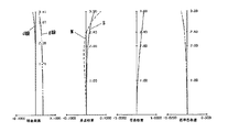
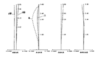
図1は実施例1のズームレンズの広角端におけるレンズ断面図、図2、図3、図4は実施例1のズームレンズの無限遠物体にフォーカスしているときの広角端、中間のズーム位置、望遠端における収差図である。 FIG. 1 is a lens cross-sectional view at the wide-angle end of the zoom lens according to the first embodiment. FIGS. 2, 3, and 4 are zoom positions at the wide-angle end and the middle when the zoom lens according to the first embodiment is focused on an object at infinity. FIG. 6 is an aberration diagram at the telephoto end.
図5は実施例2のズームレンズの広角端におけるレンズ断面図、図6、図7、図8は実施例2のズームレンズの無限遠物体にフォーカスしているときの広角端、中間のズーム位置、望遠端における収差図である。 5 is a lens cross-sectional view at the wide-angle end of the zoom lens according to the second embodiment. FIGS. 6, 7, and 8 are zoom positions at the wide-angle end and the middle when the zoom lens according to the second embodiment is focused on an infinite object. FIG. 6 is an aberration diagram at the telephoto end.
図9は実施例3のズームレンズの広角端におけるレンズ断面図、図10、図11、図12は実施例3のズームレンズの無限遠物体にフォーカスしているときの広角端、中間のズーム位置、望遠端における収差図である。 FIG. 9 is a lens cross-sectional view at the wide-angle end of the zoom lens according to the third embodiment. FIGS. 10, 11, and 12 are zoom positions at the wide-angle end and the middle when the zoom lens according to the third embodiment is focused on an object at infinity. FIG. 6 is an aberration diagram at the telephoto end.
図13は本発明の参考例1のズームレンズの広角端におけるレンズ断面図、図14、図15、図16は参考例1のズームレンズの無限遠物体にフォーカスしているときの広角端、中間のズーム位置、望遠端における収差図である。 13 is a lens cross-sectional view at the wide-angle end of the zoom lens of Reference Example 1 of the present invention , and FIGS. 14, 15, and 16 are wide-angle end and intermediate when the zoom lens of Reference Example 1 is focused on an infinite object. FIG. 6 is an aberration diagram at a zoom position at a telephoto end.
図17は実施例4のズームレンズの広角端におけるレンズ断面図、図18、図19、図20は実施例4のズームレンズの無限遠物体にフォーカスしているときの広角端、中間のズーム位置、望遠端における収差図である。 FIG. 17 is a lens cross-sectional view at the wide-angle end of the zoom lens according to the fourth embodiment. FIGS. 18, 19, and 20 are zoom positions at the wide-angle end and the middle when the zoom lens according to the fourth embodiment focuses on an object at infinity. FIG. 6 is an aberration diagram at the telephoto end.
図21は本発明のズームレンズを備えるビデオカメラ(撮像装置)の要部概略図である。 FIG. 21 is a schematic diagram of a main part of a video camera (image pickup apparatus) including the zoom lens according to the present invention.
図1、図5、図9、図13、図17のレンズ断面図において、L1は正の屈折力(光学的パワー=焦点距離の逆数)の第1レンズ群、L2は負の屈折力の第2レンズ群、L3は正の屈折力の第3レンズ群、L4は正の屈折力の第4レンズ群である。 In the lens cross-sectional views of FIGS. 1, 5, 9, 13, and 17, L1 is a first lens unit having a positive refractive power (optical power = reciprocal of focal length), and L2 is a first lens unit having a negative refractive power. 2 lens group, L3 is a third lens group having a positive refractive power, and L4 is a fourth lens group having a positive refractive power.
第3レンズ群L3は負の屈折力の第3aレンズ群L3aと防振のため(画像の変位を調整するため)に光軸と垂直方向の成分を持つように移動する正の屈折力の第3bレンズ群L3bを有している。なお、防振のための移動としては光軸上のある点を回転中心とした揺動(回転移動)でも良い。すなわち光軸と垂直方向の成分を持つように防振用の第3bレンズ群L3bを移動させれば、像の面内での移動が可能となる。 The third lens unit L3 has a positive refracting power that moves to have a component in the direction perpendicular to the optical axis for anti-vibration (to adjust the displacement of the image). It has a 3b lens unit L3b. Note that the movement for anti-vibration may be rocking (rotational movement) with a certain point on the optical axis as the rotation center. That is, if the anti-vibration 3b lens unit L3b is moved so as to have a component perpendicular to the optical axis, the image can be moved in the plane.
Gは光学フィルター、フェースプレート等に相当する光学ブロックである。IPは像面であり、ビデオカメラやデジタルスチルカメラの撮影光学系として使用する際にはCCDセンサやCMOSセンサ等の固体撮像素子(光電変換素子)の撮像面が、銀塩フィルム用カメラのときはフィルム面に相当する。SPは開口絞りであり、第3aレンズ群L3aと第3bレンズ群L3bとの間に設けている。 G is an optical block corresponding to an optical filter, a face plate, or the like. IP is an image plane, and when used as a photographing optical system for a video camera or a digital still camera, when the imaging surface of a solid-state imaging device (photoelectric conversion device) such as a CCD sensor or a CMOS sensor is a silver salt film camera Corresponds to the film surface. SP is an aperture stop, which is provided between the 3a lens unit L3a and the 3b lens unit L3b.
収差図において、dはd線、gはg線、Mはメリディオナル像面、Sはサジタル像面、倍率色収差はg線によって表している。 In the aberration diagrams, d is a d-line, g is a g-line, M is a meridional image plane, S is a sagittal image plane, and lateral chromatic aberration is represented by a g-line.
尚、以下の各実施例において広角端と望遠端のズーム位置とは変倍用のレンズ群(各実施例では第2レンズ群L2)が機構上光軸上を移動可能な範囲の両端に位置したときのズーム位置をいう。 In each of the following embodiments, the zoom positions at the wide-angle end and the telephoto end are positioned at both ends of a range in which the lens unit for zooming (the second lens unit L2 in each embodiment) can move on the optical axis on the mechanism. This is the zoom position.
各実施例では、広角端から望遠端のズーム位置へのズーミングに際して、第2レンズ群L2を像側へ移動させて変倍を行うと共に、変倍に伴う像面変動を第4レンズ群L4を物体側に凸状の軌跡の一部を有しつつ移動させて補正している。 In each embodiment, during zooming from the wide-angle end to the telephoto end zoom position, the second lens unit L2 is moved to the image side to perform zooming, and the image plane variation caused by zooming is changed to the fourth lens unit L4. The correction is performed by moving the object side while having a part of the convex locus.
また、第4レンズ群L4を光軸上移動させてフォーカシングを行うリアフォーカス方式を採用している。第4レンズ群L4の実線の曲線4aと点線の曲線4bは、各々無限遠物体と近距離物体にフォーカスしているときの広角端から望遠端のズーム位置へのズーミングの際の像面変動を補正するための移動軌跡である。
In addition, a rear focus method is employed in which focusing is performed by moving the fourth lens unit L4 on the optical axis. A
このように第4レンズ群L4を物体側へ凸状の軌跡とすることで、第3レンズ群L3と第4レンズ群L4との間の空間の有効利用を図り、レンズ全長の短縮化を効果的に達成している。なお、第1レンズ群L1と第3レンズ群L3はズーミング及びフォーカスのためには不動である。 Thus, by making the fourth lens unit L4 convex toward the object side, the space between the third lens unit L3 and the fourth lens unit L4 can be effectively used, and the shortening of the total lens length can be effectively achieved. Has been achieved. The first lens unit L1 and the third lens unit L3 do not move for zooming and focusing.
各実施例において、例えば望遠端のズーム位置において無限遠物体から近距離物体へフォーカスを行う場合には、矢印4cに示すように第4レンズ群L4を前方に繰り出すことで行っている。尚、第1レンズ群L1と第3レンズ群L3はズーミングのためには移動しない。
In each embodiment, for example, when focusing from an object at infinity to a close object at the zoom position at the telephoto end, the fourth lens unit L4 is moved forward as indicated by an
各実施例においては、第3bレンズ群(補正レンズ群)L3bを光軸と垂直方向の成分を持つように移動させて光学系全体が振動したときの像ぶれを補正するようにしている。これにより、可変頂角プリズム等の光学部材や防振のためのレンズ群を新たに付加することなく防振を行うようにし、光学系全体が大型化するのを防止している。 In each embodiment, the third-b lens group (correction lens group) L3b is moved so as to have a component perpendicular to the optical axis so as to correct image blur when the entire optical system vibrates. As a result, image stabilization is performed without newly adding an optical member such as a variable apex angle prism or a lens group for image stabilization, and the entire optical system is prevented from being enlarged.
また、第3bレンズ群L3bは負レンズと正レンズを接合した1組の接合レンズと1つの正レンズより構成し、ぶれ補正のための補正レンズ群の構成を最小限として補正レンズ群の小型化及び軽量化を図っている。これにより補正レンズを駆動するためのアクチュエータを小型化できるため装置全体の小型化が実現できるとともに、駆動の際の省電力化を図っている。 The third lens group L3b is composed of a pair of cemented lenses in which a negative lens and a positive lens are cemented together and one positive lens, and the size of the correcting lens group is minimized so that the size of the correcting lens group can be reduced. And weight reduction. As a result, the actuator for driving the correction lens can be reduced in size, so that the entire apparatus can be reduced in size and power saving during driving can be achieved.
各実施例におけるズームレンズは、第1レンズ群L1と第2レンズ群L2の合成系で形成した物体の虚像を、第3レンズ群L3と第4レンズ群L4で感光面上(撮像手段面上)IPに結像するズーム方式をとっている。 The zoom lens in each embodiment uses a third lens unit L3 and a fourth lens unit L4 to convert a virtual image of an object formed by the combined system of the first lens unit L1 and the second lens unit L2 onto the photosensitive surface (on the imaging unit surface). ) A zoom method for forming an image on the IP is adopted.
各実施例では第1レンズ群を繰り出してフォーカスを行うズームレンズに比べて、前述のようなリアフォーカス方式を採ることにより、第1レンズ群L1のレンズ有効径の増大化を効果的に防止している。 In each embodiment, as compared with the zoom lens in which the first lens unit is extended and focused, the above-described rear focus method is used to effectively prevent an increase in the effective lens diameter of the first lens unit L1. ing.
また開口絞りSPを第3レンズ群L3のレンズ群中の最も広い空気間隔の光路中に配置することにより、可動レンズ群(第2,第4レンズ群)による収差変動を少なくし、第1レンズ群L1と開口絞りSPとの間隔を短くすることにより前玉レンズ径(第1レンズ群の有効系)の縮小化を容易にしている。 Further, by arranging the aperture stop SP in the optical path with the widest air interval in the lens group of the third lens group L3, aberration variation due to the movable lens group (second and fourth lens groups) can be reduced, and the first lens. By shortening the distance between the group L1 and the aperture stop SP, the front lens diameter (effective system of the first lens group) can be easily reduced.
又3−CCD対応のビデオカメラ用の撮影レンズとして用いるときには、像面側に色分解のための色分解プリズムを配置するための空間が必要となり、通常の単板式のCCD対応のビデオカメラ用の撮影レンズに比べて長いバックフォーカスが必要となる。 In addition, when used as a photographing lens for a 3-CCD video camera, a space for arranging a color separation prism for color separation is required on the image plane side. A long back focus is required compared with a taking lens.
このため第3レンズ群L3の正の屈折力が第4レンズ群L4に対して弱くなり、第3レンズ群L3の光軸に垂直方向の偏心敏感度が小さくなる。従って第3レンズ群L3全体を光軸方向に対して垂直方向に移動させて防振を行おうとすると第3レンズ群L3の移動量が大きくなり過ぎてしまう。 For this reason, the positive refractive power of the third lens unit L3 is weak with respect to the fourth lens unit L4, and the decentration sensitivity in the direction perpendicular to the optical axis of the third lens unit L3 is reduced. Therefore, if the entire third lens unit L3 is moved in the direction perpendicular to the optical axis direction to perform image stabilization, the amount of movement of the third lens unit L3 becomes too large.
そこで各実施例では、正の屈折力の第3レンズ群L3を負の屈折力の第3aレンズ群L3aと正の屈折力の第3bレンズ群L3bに分割し、負の屈折力の第3aレンズ群L3aを用いた分だけ、第3bレンズ群L3bの正の屈折力を大きくしている。これにより第3bレンズ群L3bの偏心敏感度を大きくして、3−CCD対応のビデオカメラに用いるときでも光学系全体がコンパクトとなる防振光学系を達成している。 Therefore, in each embodiment, the third lens unit L3 having a positive refractive power is divided into a third lens unit L3a having a negative refractive power and a third b lens unit L3b having a positive refractive power, and a third lens having a negative refractive power is used. The positive refractive power of the third b lens unit L3b is increased by the amount using the group L3a. As a result, the decentration sensitivity of the third lens group L3b is increased, and an anti-vibration optical system is achieved in which the entire optical system is compact even when used in a 3-CCD video camera.
一般に高画質を目的とした撮影系では、多数枚の絞り羽を有する虹彩絞りを採用することで、ボケ味の改善を可能としている。またCCD等の撮像素子への入射光量を一時的にカットするためのシャッター機構なども静止画像を取り込む時には必要とされる。 In general, in an imaging system aiming at high image quality, the use of an iris diaphragm having a large number of diaphragm blades can improve the blur. In addition, a shutter mechanism for temporarily cutting the amount of light incident on an image sensor such as a CCD is also required when capturing a still image.
具体的には第3aレンズ群L3aと第3bレンズ群Lbの間の光軸間距離をDL、広角端のズーム位置における全系の焦点距離をfWとするとき
1.1×fW < DL < 2.5×fW ‥‥‥(1)
なる条件式を満足している。
Specifically, when the distance between the optical axes between the 3a lens unit L3a and the 3b lens unit Lb is DL, and the focal length of the entire system at the zoom position at the wide angle end is fW, 1.1 × fW <DL <2. .5xfW (1)
The following conditional expression is satisfied.
この条件式(1)を満足することにより、各実施例では第3レンズ群L3のレンズ間(第3aレンズ群L3aと第3bレンズ群L3bの間)をそのための空間として利用し、その空間内に絞りSP、シャッター、ND挿脱機構等を第3レンズ群L3内に収納することにより鏡筒構造を簡素化させている。 By satisfying this conditional expression (1), each embodiment uses the space between the lenses of the third lens unit L3 (between the 3a lens unit L3a and the 3b lens unit L3b) as a space for that purpose. Further, the aperture SP, shutter, ND insertion / removal mechanism and the like are housed in the third lens unit L3, thereby simplifying the lens barrel structure.
更に好ましくは条件式(1)の数値範囲を
1.4×fW < DL < 2.2×fW ‥‥‥(1a)
を満足させるのが良い。
More preferably, the numerical range of the conditional expression (1) is 1.4 × fW <DL <2.2 × fW (1a)
It is good to satisfy.
又、前記第3aレンズ群と第3bレンズ群との空気間隔をDL、前記第3レンズ群の全長をDTとするとき
0.34 <DL/DT < 0.43 ‥‥‥(2)
なる条件を満足するようにしている。
Further, when the air space between the third lens group and the third lens group is DL, and the total length of the third lens group is DT, 0.34 <DL / DT <0.43 (2)
To satisfy the following conditions.
これによって、第3レンズ群L3中のレンズ構成を適切に設定することができ、更に絞り等の光学部材の配置を容易にしている。 Accordingly, the lens configuration in the third lens unit L3 can be set appropriately, and the arrangement of optical members such as a diaphragm is facilitated.
更に好ましくは条件式(2)の数値範囲を
0.36 <DL/DT < 0.41 ‥‥‥(2a)
とするのが良い。
More preferably, the numerical range of conditional expression (2) is 0.36 <DL / DT <0.41 (2a)
It is good to do.
そして絞りSP前後の間隔を十分長く確保した上で、高い光学性能を実現する為に第3aレンズ群L3aを物体側の面が凹形状又は物体側と像側の面が凹形状の負レンズと物体側と像側の面が凸形状の正レンズを接合した接合レンズ又は独立の2つのレンズより構成し、第3bレンズL3b群を物体側より像側へ順に、像面側の面が凹でメニスカス形状の負レンズと2枚の正レンズで構成している。 Then, in order to achieve a high optical performance while ensuring a sufficiently long distance before and after the stop SP, the third lens unit L3a includes a negative lens having a concave surface on the object side or a concave surface on the object side and the image side. The object side and image side surfaces are composed of a cemented lens in which convex positive lenses are cemented or two independent lenses, and the third b lens L3b group is arranged in order from the object side to the image side, and the image side surface is concave. It is composed of a meniscus negative lens and two positive lenses.
これにより第3aレンズ群L3aからの発散光束を略アフォーカルとする際、絞りSP空間を広く取りながらも良好な光学性能を保ちかつ、防振時の偏心収差の変動も良好に補正している。 As a result, when the divergent light beam from the third-a lens unit L3a is made approximately afocal, good optical performance is maintained while widening the aperture SP space, and fluctuations in decentration aberrations during image stabilization are also well corrected. .
第3aレンズ群L3aと第3bレンズ群L3bの各々の1以上の面を非球面形状としている。 One or more surfaces of each of the third-a lens unit L3a and the third-b lens unit L3b are aspherical.
これによれば各レンズ群内で発生する諸収差を小さくし、防振時の光学性能の劣化を抑制するのが容易となる。 According to this, it becomes easy to reduce various aberrations occurring in each lens group and to suppress deterioration of optical performance during image stabilization.
特に第3aレンズ群L3aの最も像側のレンズ面、第3bレンズ群L3bの凸状のレンズ面を非球面形状とするのが良く、これによれば各レンズ群内で発生する球面収差、コマ収差を小さくし、防振時に発生する偏心収差、特に偏心コマ収差を良好に補正するのが容易となる。 In particular, the most image-side lens surface of the 3a lens unit L3a and the convex lens surface of the 3b lens unit L3b are preferably aspherical. According to this, spherical aberration and coma generated in each lens unit are improved. Aberrations are reduced, and it becomes easy to satisfactorily correct decentration aberrations, particularly decentration coma aberration, that occur during image stabilization.
尚、非球形状の面の位置は、前述した位置と異なっていてもよい。 The position of the non-spherical surface may be different from the position described above.
防振用のレンズ群である正の屈折力の第3bレンズ群L3bは1以上の負レンズを有するのが良い。 The third-b lens unit L3b having a positive refractive power, which is an anti-vibration lens unit, may include one or more negative lenses.
第3bレンズ群L3bを防振の為に偏心させたときの倍率色収差や偏心させたことによる像面湾曲を補正するためには、第3bレンズ群L3b単独で出来るだけ色収差が補正されており、かつペッツバール和が小さくなっていることが望ましい。従って第3bレンズ群L3bには少なくとも1枚の負レンズを含むように構成するのが、色収差の補正やペッツバール和を小さくするのに効果的である。さらにペッツバール和を小さくするためには該負レンズの材料の屈折率を1.8以上とすることが好ましい。 In order to correct the lateral chromatic aberration when the third lens unit L3b is decentered for image stabilization and the curvature of field due to the decentering, the third lens unit L3b alone corrects chromatic aberration as much as possible. In addition, it is desirable that the Petzval sum is small. Therefore, it is effective for correcting the chromatic aberration and reducing the Petzval sum to include at least one negative lens in the third lens group L3b. Further, in order to reduce the Petzval sum, it is preferable that the refractive index of the material of the negative lens is 1.8 or more.
またこのとき、全系の色収差を良好に保つためには、第3bレンズ群L3b以外の第3aレンズ群L3a内に少なくとも1枚の正レンズを有するようにするのが良い。 At this time, in order to maintain good chromatic aberration of the entire system, it is preferable to have at least one positive lens in the third a lens unit L3a other than the third b lens unit L3b.
第2レンズ群L2は物体側から像側へ順に、像側の面が凹でメニスカス形状の負レンズ、物体側の面が凹形状の負レンズ、物体側と像側の面が凸形状の正レンズ、物体側と像側の面が凹形状の負レンズで構成するのが良い。 The second lens unit L2, in order from the object side to the image side, is a negative meniscus lens having a concave image side surface, a negative lens having a concave surface on the object side, and a positive lens having convex surfaces on the object side and the image side. It is preferable that the lens and the object-side and image-side surfaces are concave lenses.
これによれば全変倍範囲にわたり、倍率色収差を良好に補正するのが容易となる。 According to this, it becomes easy to satisfactorily correct lateral chromatic aberration over the entire zooming range.
第4レンズ群L4は1枚以上の負レンズと2枚の正レンズで構成し、かつ1つ以上の面を非球面形状とするのが望ましい。 The fourth lens unit L4 is preferably composed of one or more negative lenses and two positive lenses, and one or more surfaces are preferably aspherical.
これによれば3CCD対応のカメラに適用する為に、バックフォーカスを伸ばしたとき、第4レンズ群L4の屈折力が強くなると共に、軸上光線が第4レンズ群L4を通る高さが高くなって球面収差が発生するのを良好に補正することが容易となる。 According to this, when applied to a 3CCD camera, when the back focus is extended, the refractive power of the fourth lens unit L4 increases and the height of the axial ray passing through the fourth lens unit L4 increases. Thus, it is easy to satisfactorily correct the occurrence of spherical aberration.
第4レンズ群L4は物体側と像側の面が凸形状の正レンズ、物体側の面が凸でメニスカス形状の負レンズ、物体側と像側の面が凸形状の正レンズより構成するのが収差補正の為に良い。 The fourth lens unit L4 includes a positive lens having a convex surface on the object side and the image side, a negative lens having a convex meniscus shape on the object side, and a positive lens having a convex surface on the object side and the image side. Is good for aberration correction.
各実施例では、以上のように、各要素を設定することによって、ズームレンズの一部を構成する比較的小型軽量のレンズ群L3bを光軸と垂直方向の成分を持つように移動させて、該ズームレンズが振動したときの画像のぶれを補正(調整)することができる防振機能を有しながらも、光量制御のためのNDフィルター、虹彩絞り、メカニカルシャッター等を光路内に挿入するための空間を十分多く確保し、且つ機構上の簡素化を図っている。又、第3レンズ群L3を適切なパワー配置とすることで射出瞳位置も100mm以上の長さを確保でき、CCDを用いた撮像装置に十分対応できるズームレンズを達成している。 In each embodiment, as described above, by setting each element, the relatively small and light lens group L3b constituting a part of the zoom lens is moved so as to have a component perpendicular to the optical axis. In order to insert an ND filter, iris diaphragm, mechanical shutter, etc. for light quantity control into the optical path while having an image stabilization function that can correct (adjust) image blur when the zoom lens vibrates A sufficient amount of space is secured and the mechanism is simplified. Further, by setting the third lens unit L3 to an appropriate power arrangement, the exit pupil position can be secured at a length of 100 mm or more, and a zoom lens that can sufficiently cope with an imaging device using a CCD is achieved.
次に、実施例1〜3、参考例1、実施例4に各々対応する数値実施例1〜5の数値データを示す。各数値実施例において、iは物体側からの光学面の順序を示し、Riは第i番目の光学面(第i面)の曲率半径、Diは第i面と第(i+1)面との間の間隔、Niとνiはそれぞれd線に対する第i番目の光学部材の屈折率、アッベ数を示す。fは焦点距離、FnoはFナンバー、ωは半画角である。 Next, numerical data of Numerical Examples 1 to 5 respectively corresponding to Examples 1 to 3, Reference Example 1, and Example 4 are shown. In each numerical example, i indicates the order of the optical surfaces from the object side, Ri is the radius of curvature of the i-th optical surface (i-th surface), and Di is between the i-th surface and the (i + 1) -th surface. , Ni and νi respectively indicate the refractive index and Abbe number of the i-th optical member with respect to the d-line. f is a focal length, Fno is an F number, and ω is a half angle of view.
また、各数値実施例1,5において最も像側の7つの面、数値実施例2において最も像側の5つの面、数値実施例3,4において最も像側の6つの面は、色分解プリズム、フェースプレート、各種フィルター等に相当するガラスブロックGを構成する面である。 In each of Numerical Examples 1 and 5, seven surfaces closest to the image side, five surfaces closest to the image side in Numerical Example 2, and six surfaces closest to the image side in Numerical Examples 3 and 4 are color separation prisms. This is a surface constituting a glass block G corresponding to a face plate, various filters and the like.
またkを円錐定数、B、C、D、Eをそれぞれ非球面係数、光軸からの高さHの位置での光軸方向の変位を面頂点を基準にしてXとするとき、非球面形状は
、
Further, when k is a conic constant, B, C, D, and E are aspherical coefficients, respectively, and the displacement in the optical axis direction at the position of the height H from the optical axis is X with respect to the surface vertex, the aspherical shape Is

で表示される。但しRは近軸曲率半径である。また、例えば「e−Z」の表示は「10-Z」を意味する。又、各数値実施例における上述した条件式との対応を表1に示す。
数値実施例 1
f=4.51〜 50.48 Fno= 1.65 〜 1.95 2ω=70.7゜ 〜 7.2゜
R 1 = 822.890 D 1 = 3.00 N 1 = 1.65844 ν 1 = 50.9
R 2 = 57.792 D 2 = 20.35
R 3 = 93.476 D 3 = 8.18 N 2 = 1.51633 ν 2 = 64.1
R 4 = -139.363 D 4 = 1.50
R 5 = 69.540 D 5 = 1.76 N 3 = 1.84666 ν 3 = 23.9
R 6 = 39.272 D 6 = 10.02 N 4 = 1.48749 ν 4 = 70.2
R 7 = -438.344 D 7 = 0.25
R 8 = 37.114 D 8 = 7.22 N 5 = 1.69680 ν 5 = 55.5
R 9 = 209.209 D 9 = 可変
R10 = 200.560 D10 = 1.00 N 6 = 1.88300 ν 6 = 40.8
R11 = 8.991 D11 = 3.63
R12 = -42.912 D12 = 0.90 N 7 = 1.88300 ν 7 = 40.8
R13 = 67.644 D13 = 0.44
R14 = 16.001 D14 = 3.90 N 8 = 1.84666 ν 8 = 23.9
R15 = -41.123 D15 = 0.90 N 9 = 1.77250 ν 9 = 49.6
R16 = 28.679 D16 = 可変
R17 = -14.783 D17 = 0.90 N10 = 1.77250 ν10 = 49.6
R18 = 30.123 D18 = 4.50 N11 = 1.69895 ν11 = 30.1
R19 = -21.243 D19 = 7.00
R20 = 絞り D20 = 1.50
R21 = 110.389 D21 = 1.20 N12 = 1.80518 ν12 = 25.4
R22 = 37.919 D22 = 3.75 N13 = 1.58313 ν13 = 59.4
*R23 = -44.470 D23 = 0.15
R24 = 103.541 D24 = 2.40 N14 = 1.48749 ν14 = 70.2
R25 = -113.482 D25 = 可変
*R26 = 27.502 D26 = 3.80 N15 = 1.58313 ν15 = 59.4
R27 = -59.571 D27 = 0.20
R28 = 83.356 D28 = 0.90 N16 = 1.84666 ν16 = 23.9
R29 = 21.414 D29 = 4.70 N17 = 1.48749 ν17 = 70.2
R30 = -57.843 D30 = 4.14
R31 = ∞ D31 = 1.00 N18 = 1.52000 ν18 = 64.0
R32 = ∞ D32 = 0.00
R33 = ∞ D33 = 1.36 N19 = 1.55000 ν19 = 64.0
R34 = ∞ D34 = 0.50
R35 = ∞ D35 = 21.00 N20 = 1.52000 ν20 = 64.0
R36 = ∞ D36 = 0.70 N21 = 1.55000 ν21 = 60.0
R37 = ∞
\焦点距離 4.51 13.12 50.48
可変間隔\
D 9 1.22 18.44 29.92
D16 33.60 16.38 4.90
D25 12.14 9.85 12.75
*印は非球面を表し、非球面係数は
R23 k=-4.9040 B=-5.44038e-04 C= 3.71831e-05 D= 0.0 E=0.0
R26 k=-2.9022 B= 2.34392e-04 C=-2.04772e-05 D= 2.25500e-06 E=-1.16811e-07
数値実施例 2
f=5.07〜 100.98 Fno= 1.65 〜 1.97 2ω=64.5゜ 〜 3.6゜
R 1 = 88.779 D 1 = 2.80 N 1 = 1.84666 ν 1 = 23.9
R 2 = 54.271 D 2 = 2.80
R 3 = 81.181 D 3 = 9.50 N 2 = 1.43387 ν 2 = 95.1
R 4 = -175.805 D 4 = 0.25
R 5 = 41.749 D 5 = 8.80 N 3 = 1.60311 ν 3 = 60.6
R 6 = 255.887 D 6 = 可変
R 7 = 71.606 D 7 = 1.10 N 4 = 1.88300 ν 4 = 40.8
R 8 = 9.706 D 8 = 4.80
R 9 = -33.980 D 9 = 1.00 N 5 = 1.88300 ν 5 = 40.8
R10 = 108.117 D10 = 0.70
R11 = 20.608 D11 = 4.20 N 6 = 1.84666 ν 6 = 23.9
R12 = -52.272 D12 = 0.90 N 7 = 1.77250 ν 7 = 49.6
R13 = 50.374 D13 = 可変
R14 = -27.907 D14 = 0.90 N 8 = 1.77250 ν 8 = 49.6
R15 = 29.634 D15 = 4.00 N 9 = 1.69895 ν 9 = 30.1
R16 = -41.906 D16 = 7.00
R17 = 絞り D17 = 1.98
R18 = 81.781 D18 = 1.20 N10 = 1.80518 ν10 = 25.4
R19 = 27.378 D19 = 5.50 N11 = 1.58313 ν11 = 59.4
*R20 = -68.445 D20 = 0.15
R21 = 66.065 D21 = 3.50 N12 = 1.48749 ν12 = 70.2
R22 = -81.266 D22 = 可変
*R23 = 35.362 D23 = 3.70 N13 = 1.58313 ν13 = 59.4
R24 = -87.646 D24 = 1.35
R25 = 56.308 D25 = 1.10 N14 = 1.84666 ν14 = 23.9
R26 = 24.220 D26 = 4.50 N15 = 1.51633 ν15 = 64.1
R27 = -187.715 D27 = 4.00
R28 = ∞ D28 = 1.30 N16 = 1.55000 ν16 = 60.0
R29 = ∞ D29 = 2.00 N17 = 1.52000 ν17 = 69.0
R30 = ∞ D30 = 20.00 N18 = 1.58913 ν18 = 61.0
R31 = ∞ D31 = 1.00 N19 = 1.52000 ν19 = 64.0
R32 = ∞
\焦点距離 5.07 17.09 100.98
可変間隔\
D 6 1.14 29.70 48.74
D13 52.88 24.32 5.28
D22 19.03 15.41 19.84
*印は非球面を表し、非球面係数は
R20 k= 1.3831 B=1.85431e-04 C=-1.22227e-05 D=0.0 E=0.0
R23 k=-1.7894 B=-8.81701e-05 C=-8.32135e-06 D=0.0 E=0.0
数値実施例 3
f=4.15〜 47.99 Fno= 1.65 〜 1.95 2ω=75.3゜ 〜 7.6゜
R 1 = 822.890 D 1 = 3.00 N 1 = 1.65844 ν 1 = 50.9
R 2 = 59.873 D 2 = 23.23
R 3 = 98.566 D 3 = 8.07 N 2 = 1.51633 ν 2 = 64.1
R 4 = -152.955 D 4 = 1.50
R 5 = 61.578 D 5 = 1.76 N 3 = 1.84666 ν 3 = 23.9
R 6 = 36.004 D 6 = 9.25 N 4 = 1.48749 ν 4 = 70.2
R 7 = -903.961 D 7 = 0.25
R 8 = 35.597 D 8 = 6.20 N 5 = 1.69680 ν 5 = 55.5
R 9 = 188.576 D 9 = 可変
R10 = 128.267 D10 = 1.00 N 6 = 1.88300 ν 6 = 40.8
R11 = 8.759 D11 = 4.09
R12 = -33.581 D12 = 0.90 N 7 = 1.88300 ν 7 = 40.8
R13 = 74.512 D13 = 0.44
R14 = 18.309 D14 = 3.90 N 8 = 1.84666 ν 8 = 23.9
R15 = -27.722 D15 = 0.90 N 9 = 1.77250 ν 9 = 49.6
R16 = 47.644 D16 = 可変
R17 = -18.306 D17 = 0.90 N10 = 1.77250 ν10 = 49.6
R18 = 22.108 D18 = 4.50 N11 = 1.69895 ν11 = 30.1
R19 = -26.555 D19 = 1.00
R20 = 絞り D20 = 7.20
R21 = 102.153 D21 = 1.20 N12 = 1.80518 ν12 = 25.4
R22 = 32.290 D22 = 4.50 N13 = 1.58313 ν13 = 59.4
*R23 = -53.663 D23 = 0.15
R24 = 82.507 D24 = 3.00 N14 = 1.48749 ν14 = 70.2
R25 = -82.507 D25 = 可変
*R26 = 25.947 D26 = 3.50 N15 = 1.58313 ν15 = 59.4
R27 = -110.664 D27 = 0.20
R28 = 35.366 D28 = 0.90 N16 = 1.84666 ν16 = 23.9
R29 = 16.126 D29 = 4.70 N17 = 1.48749 ν17 = 70.2
R30 = -78.072 D30 = 3.95
R31 = ∞ D31 = 0.43 N18 = 1.52000 ν18 = 64.0
R32 = ∞ D32 = 1.86 N19 = 1.55000 ν19 = 63.0
R33 = ∞ D33 = 1.00
R34 = ∞ D34 = 21.00 N20 = 1.52000 ν20 = 64.0
R35 = ∞ D35 = 0.70 N21 = 1.55000 ν21 = 59.0
R36 = ∞
\焦点距離 4.15 12.24 47.99
可変間隔\
D 9 1.06 18.32 29.82
D16 32.55 15.29 3.78
D25 11.91 10.04 13.15
*印は非球面を表し、非球面係数は
R23 k=-3.5400 B=-9.76098e-05 C= 8.21658e-07 D= 0.0 E= 0.0
R26 k=-0.1069 B=-6.07681e-04 C=-2.06091e-05 D= 2.27537e-06 E=-1.18169e-07
数値実施例 4
f=4.15〜 48.89 Fno= 1.67 〜 1.95 2ω=75.3゜ 〜 7.5゜
R 1 = 633.105 D 1 = 3.00 N 1 = 1.65844 ν 1 = 50.9
R 2 = 58.632 D 2 = 19.90
R 3 = 118.507 D 3 = 6.80 N 2 = 1.51633 ν 2 = 64.1
R 4 = -130.457 D 4 = 1.50
R 5 = 55.362 D 5 = 1.76 N 3 = 1.84666 ν 3 = 23.9
R 6 = 33.744 D 6 = 8.50 N 4 = 1.48749 ν 4 = 70.2
R 7 = 1148.002 D 7 = 0.25
R 8 = 35.332 D 8 = 6.30 N 5 = 1.69680 ν 5 = 55.5
R 9 = 237.585 D 9 = 可変
R10 = 70.424 D10 = 1.00 N 6 = 1.88300 ν 6 = 40.8
R11 = 7.870 D11 = 3.90
R12 = -25.097 D12 = 0.90 N 7 = 1.88300 ν 7 = 40.8
R13 = 63.711 D13 = 0.44
R14 = 18.279 D14 = 3.90 N 8 = 1.84666 ν 8 = 23.9
R15 = -27.134 D15 = 0.90 N 9 = 1.77250 ν 9 = 49.6
R16 = 148.026 D16 = 可変
R17 = -26.420 D17 = 0.90 N10 = 1.69680 ν10 = 55.5
R18 = 16.735 D18 = 3.10 N11 = 1.68893 ν11 = 31.1
*R19 = -43.070 D19 = 1.00
R20 = 絞り D20 = 7.20
*R21 = 20.090 D21 = 3.50 N12 = 1.58913 ν12 = 61.3
R22 = 105.342 D22 = 1.00 N13 = 1.80518 ν13 = 25.4
R23 = 25.853 D23 = 2.00
R24 = -78.674 D24 = 3.50 N14 = 1.48749 ν14 = 70.2
R25 = -28.185 D25 = 可変
*R26 = 23.688 D26 = 3.50 N15 = 1.58313 ν15 = 59.4
R27 = -66.288 D27 = 0.20
R28 = 28.300 D28 = 0.90 N16 = 1.84666 ν16 = 23.9
R29 = 15.107 D29 = 4.70 N17 = 1.48749 ν17 = 70.2
R30 = -78.353 D30 = 3.95
R31 = ∞ D31 = 0.43 N18 = 1.51633 ν18 = 64.2
R32 = ∞ D32 = 1.36 N19 = 1.55232 ν19 = 63.4
R33 = ∞ D33 = 1.00
R34 = ∞ D34 = 21.00 N20 = 1.51633 ν20 = 64.2
R35 = ∞ D35 = 0.70 N21 = 1.55671 ν21 = 58.6
R36 = ∞
\焦点距離 4.15 12.54 48.89
可変間隔\
D 9 1.06 18.32 29.82
D16 32.27 15.01 3.50
D25 7.61 5.62 8.93
*印は非球面を表し、非球面係数は
R19 k=-83.0533 B=-9.29815e-03 C= 3.10399e-03 D=-4.86106e-04 E= 0.0
R21 k=-0.9806 B=-4.84116e-04 C= 3.81514e-04 D=-4.94727e-05 E= 0.0
R26 k=-0.4882 B=-6.57830e-04 C=-4.80325e-05 D=7.43907e-06 E=-5.41951e-07
数値実施例 5
f=4.43〜 48.49 Fno= 1.65 〜 1.95 2ω=71.7゜ 〜 7.5゜
R 1 =-1074.538 D 1 = 2.00 N 1 = 1.84666 ν 1 = 23.9
R 2 = 76.294 D 2 = 14.37 N 2 = 1.63854 ν 2 = 55.4
R 3 = -157.324 D 3 = 0.30
R 4 = 97.509 D 4 = 5.67 N 3 = 1.63854 ν 3 = 55.4
R 5 = 484.397 D 5 = 0.20
R 6 = 46.928 D 6 = 7.64 N 4 = 1.77250 ν 4 = 49.6
R 7 = 124.924 D 7 = 可変
R 8 = 119.991 D 8 = 1.00 N 5 = 1.88300 ν 5 = 40.8
R 9 = 10.524 D 9 = 6.48
R10 = -27.999 D10 = 0.90 N 6 = 1.88300 ν 6 = 40.8
R11 = -158.469 D11 = 0.44
R12 = 20.700 D12 = 6.60 N 7 = 1.84666 ν 7 = 23.9
R13 = -18.931 D13 = 0.90 N 8 = 1.77250 ν 8 = 49.6
R14 = 25.201 D14 = 可変
R15 = -15.072 D15 = 0.90 N 9 = 1.77250 ν 9 = 49.6
R16 = 20.781 D16 = 4.50 N10 = 1.69895 ν10 = 30.1
R17 = -21.216 D17 = 7.00
R18 = 絞り D18 = 1.50
R19 = 291.276 D19 = 1.20 N11 = 1.80518 ν11 = 25.4
R20 = 29.390 D20 = 3.75 N12 = 1.58313 ν12 = 59.4
*R21 = -48.998 D21 = 0.15
R22 = 93.796 D22 = 2.40 N13 = 1.48749 ν13 = 70.2
R23 = -60.653 D23 = 可変
*R24 = 31.483 D24 = 3.80 N14 = 1.58313 ν14 = 59.4
R25 = -56.156 D25 = 0.20
R26 = 72.538 D26 = 0.90 N15 = 1.84666 ν15 = 23.9
R27 = 24.839 D27 = 4.70 N16 = 1.48749 ν16 = 70.2
R28 = -62.010 D28 = 3.70
R29 = ∞ D29 = 1.00 N17 = 1.52000 ν17 = 64.0
R30 = ∞ D30 = 1.00
R31 = ∞ D31 = 1.36 N18 = 1.55000 ν18 = 63.0
R32 = ∞ D32 = 0.50
R33 = ∞ D33 = 21.00 N19 = 1.52000 ν19 = 64.0
R34 = ∞ D34 = 0.70 N20 = 1.55000 ν20 = 58.0
R35 = ∞
\焦点距離 4.43 12.87 48.49
可変間隔\
D 7 1.17 22.17 36.17
D14 42.67 22.67 7.67
D23 12.72 10.63 11.07
*印は非球面を表し、非球面係数は
R21 k=-5.0131 B=-5.77223e-04 C= 6.07070e-06 D= 0.0 E= 0.0
R24 k=-2.9167 B=-2.87701e-05 C=-1.07167e-05 D= 9.10871e-07 E=-3.64174e-08
Is displayed. Where R is the paraxial radius of curvature. For example, “e-Z” means “10 −Z ”. Table 1 shows the correspondence with the above-described conditional expressions in each numerical example.
Numerical example 1
f = 4.51 to 50.48 Fno = 1.65 to 1.95 2ω = 70.7 ° to 7.2 °
R 5 = 69.540 D 5 = 1.76
R 6 = 39.272 D 6 = 10.02
R 7 = -438.344 D 7 = 0.25
R 9 = 209.209 D 9 = Variable
R10 = 200.560 D10 = 1.00 N 6 = 1.88300 ν 6 = 40.8
R11 = 8.991 D11 = 3.63
R12 = -42.912 D12 = 0.90 N 7 = 1.88300 ν 7 = 40.8
R13 = 67.644 D13 = 0.44
R14 = 16.001 D14 = 3.90
R15 = -41.123 D15 = 0.90 N 9 = 1.77250 ν 9 = 49.6
R16 = 28.679 D16 = variable
R17 = -14.783 D17 = 0.90 N10 = 1.77250 ν10 = 49.6
R18 = 30.123 D18 = 4.50 N11 = 1.69895 ν11 = 30.1
R19 = -21.243 D19 = 7.00
R20 = Aperture D20 = 1.50
R21 = 110.389 D21 = 1.20 N12 = 1.80518 ν12 = 25.4
R22 = 37.919 D22 = 3.75 N13 = 1.58313 ν13 = 59.4
* R23 = -44.470 D23 = 0.15
R24 = 103.541 D24 = 2.40 N14 = 1.48749 ν14 = 70.2
R25 = -113.482 D25 = variable
* R26 = 27.502 D26 = 3.80 N15 = 1.58313 ν15 = 59.4
R27 = -59.571 D27 = 0.20
R28 = 83.356 D28 = 0.90 N16 = 1.84666 ν16 = 23.9
R29 = 21.414 D29 = 4.70 N17 = 1.48749 ν17 = 70.2
R30 = -57.843 D30 = 4.14
R31 = ∞ D31 = 1.00 N18 = 1.52000 ν18 = 64.0
R32 = ∞ D32 = 0.00
R33 = ∞ D33 = 1.36 N19 = 1.55000 ν19 = 64.0
R34 = ∞ D34 = 0.50
R35 = ∞ D35 = 21.00 N20 = 1.52000 ν20 = 64.0
R36 = ∞ D36 = 0.70 N21 = 1.55000 ν21 = 60.0
R37 = ∞
\ Focal length 4.51 13.12 50.48
Variable interval \
D 9 1.22 18.44 29.92
D16 33.60 16.38 4.90
D25 12.14 9.85 12.75
* Indicates an aspheric surface, and the aspheric coefficient is
R23 k = -4.9040 B = -5.44038e-04 C = 3.71831e-05 D = 0.0 E = 0.0
R26 k = -2.9022 B = 2.34392e-04 C = -2.04772e-05 D = 2.25500e-06 E = -1.16811e-07
Numerical example 2
f = 5.07 to 100.98 Fno = 1.65 to 1.97 2ω = 64.5 ° to 3.6 °
R 5 = 41.749 D 5 = 8.80
R 6 = 255.887 D 6 = variable
R 7 = 71.606 D 7 = 1.10
R 9 = -33.980 D 9 = 1.00 N 5 = 1.88300 ν 5 = 40.8
R10 = 108.117 D10 = 0.70
R11 = 20.608 D11 = 4.20 N 6 = 1.84666 ν 6 = 23.9
R12 = -52.272 D12 = 0.90 N 7 = 1.77250 ν 7 = 49.6
R13 = 50.374 D13 = variable
R14 = -27.907 D14 = 0.90
R15 = 29.634 D15 = 4.00 N 9 = 1.69895 ν 9 = 30.1
R16 = -41.906 D16 = 7.00
R17 = Aperture D17 = 1.98
R18 = 81.781 D18 = 1.20 N10 = 1.80518 ν10 = 25.4
R19 = 27.378 D19 = 5.50 N11 = 1.58313 ν11 = 59.4
* R20 = -68.445 D20 = 0.15
R21 = 66.065 D21 = 3.50 N12 = 1.48749 ν12 = 70.2
R22 = -81.266 D22 = variable
* R23 = 35.362 D23 = 3.70 N13 = 1.58313 ν13 = 59.4
R24 = -87.646 D24 = 1.35
R25 = 56.308 D25 = 1.10 N14 = 1.84666 ν14 = 23.9
R26 = 24.220 D26 = 4.50 N15 = 1.51633 ν15 = 64.1
R27 = -187.715 D27 = 4.00
R28 = ∞ D28 = 1.30 N16 = 1.55000 ν16 = 60.0
R29 = ∞ D29 = 2.00 N17 = 1.52000 ν17 = 69.0
R30 = ∞ D30 = 20.00 N18 = 1.58913 ν18 = 61.0
R31 = ∞ D31 = 1.00 N19 = 1.52000 ν19 = 64.0
R32 = ∞
\ Focal length 5.07 17.09 100.98
Variable interval \
D 6 1.14 29.70 48.74
D13 52.88 24.32 5.28
D22 19.03 15.41 19.84
* Indicates an aspheric surface, and the aspheric coefficient is
R20 k = 1.3831 B = 1.85431e-04 C = -1.22227e-05 D = 0.0 E = 0.0
R23 k = -1.7894 B = -8.81701e-05 C = -8.32135e-06 D = 0.0 E = 0.0
Numerical example 3
f = 4.15-47.99 Fno = 1.65-1.95 2ω = 75.3 °-7.6 °
R 5 = 61.578 D 5 = 1.76
R 6 = 36.004 D 6 = 9.25
R 7 = -903.961 D 7 = 0.25
R 9 = 188.576 D 9 = variable
R10 = 128.267 D10 = 1.00 N 6 = 1.88300 ν 6 = 40.8
R11 = 8.759 D11 = 4.09
R12 = -33.581 D12 = 0.90 N 7 = 1.88300 ν 7 = 40.8
R13 = 74.512 D13 = 0.44
R14 = 18.309 D14 = 3.90
R15 = -27.722 D15 = 0.90 N 9 = 1.77250 ν 9 = 49.6
R16 = 47.644 D16 = variable
R17 = -18.306 D17 = 0.90 N10 = 1.77250 ν10 = 49.6
R18 = 22.108 D18 = 4.50 N11 = 1.69895 ν11 = 30.1
R19 = -26.555 D19 = 1.00
R20 = Aperture D20 = 7.20
R21 = 102.153 D21 = 1.20 N12 = 1.80518 ν12 = 25.4
R22 = 32.290 D22 = 4.50 N13 = 1.58313 ν13 = 59.4
* R23 = -53.663 D23 = 0.15
R24 = 82.507 D24 = 3.00 N14 = 1.48749 ν14 = 70.2
R25 = -82.507 D25 = variable
* R26 = 25.947 D26 = 3.50 N15 = 1.58313 ν15 = 59.4
R27 = -110.664 D27 = 0.20
R28 = 35.366 D28 = 0.90 N16 = 1.84666 ν16 = 23.9
R29 = 16.126 D29 = 4.70 N17 = 1.48749 ν17 = 70.2
R30 = -78.072 D30 = 3.95
R31 = ∞ D31 = 0.43 N18 = 1.52000 ν18 = 64.0
R32 = ∞ D32 = 1.86 N19 = 1.55000 ν19 = 63.0
R33 = ∞ D33 = 1.00
R34 = ∞ D34 = 21.00 N20 = 1.52000 ν20 = 64.0
R35 = ∞ D35 = 0.70 N21 = 1.55000 ν21 = 59.0
R36 = ∞
\ Focal length 4.15 12.24 47.99
Variable interval \
D 9 1.06 18.32 29.82
D16 32.55 15.29 3.78
D25 11.91 10.04 13.15
* Indicates an aspheric surface, and the aspheric coefficient is
R23 k = -3.5400 B = -9.76098e-05 C = 8.21658e-07 D = 0.0 E = 0.0
R26 k = -0.1069 B = -6.07681e-04 C = -2.06091e-05 D = 2.27537e-06 E = -1.18169e-07
Numerical example 4
f = 4.15-48.89 Fno = 1.67-1.95 2ω = 75.3 °-7.5 °
R 5 = 55.362 D 5 = 1.76
R 6 = 33.744 D 6 = 8.50
R 7 = 1148.002 D 7 = 0.25
R 9 = 237.585 D 9 = variable
R10 = 70.424 D10 = 1.00 N 6 = 1.88300 ν 6 = 40.8
R11 = 7.870 D11 = 3.90
R12 = -25.097 D12 = 0.90 N 7 = 1.88300 ν 7 = 40.8
R13 = 63.711 D13 = 0.44
R14 = 18.279 D14 = 3.90
R15 = -27.134 D15 = 0.90 N 9 = 1.77250 ν 9 = 49.6
R16 = 148.026 D16 = variable
R17 = -26.420 D17 = 0.90 N10 = 1.69680 ν10 = 55.5
R18 = 16.735 D18 = 3.10 N11 = 1.68893 ν11 = 31.1
* R19 = -43.070 D19 = 1.00
R20 = Aperture D20 = 7.20
* R21 = 20.090 D21 = 3.50 N12 = 1.58913 ν12 = 61.3
R22 = 105.342 D22 = 1.00 N13 = 1.80518 ν13 = 25.4
R23 = 25.853 D23 = 2.00
R24 = -78.674 D24 = 3.50 N14 = 1.48749 ν14 = 70.2
R25 = -28.185 D25 = variable
* R26 = 23.688 D26 = 3.50 N15 = 1.58313 ν15 = 59.4
R27 = -66.288 D27 = 0.20
R28 = 28.300 D28 = 0.90 N16 = 1.84666 ν16 = 23.9
R29 = 15.107 D29 = 4.70 N17 = 1.48749 ν17 = 70.2
R30 = -78.353 D30 = 3.95
R31 = ∞ D31 = 0.43 N18 = 1.51633 ν18 = 64.2
R32 = ∞ D32 = 1.36 N19 = 1.55232 ν19 = 63.4
R33 = ∞ D33 = 1.00
R34 = ∞ D34 = 21.00 N20 = 1.51633 ν20 = 64.2
R35 = ∞ D35 = 0.70 N21 = 1.55671 ν21 = 58.6
R36 = ∞
\ Focal length 4.15 12.54 48.89
Variable interval \
D 9 1.06 18.32 29.82
D16 32.27 15.01 3.50
D25 7.61 5.62 8.93
* Indicates an aspheric surface, and the aspheric coefficient is
R19 k = -83.0533 B = -9.29815e-03 C = 3.10399e-03 D = -4.86106e-04 E = 0.0
R21 k = -0.9806 B = -4.84116e-04 C = 3.81514e-04 D = -4.94727e-05 E = 0.0
R26 k = -0.4882 B = -6.57830e-04 C = -4.80325e-05 D = 7.43907e-06 E = -5.41951e-07
Numerical example 5
f = 4.43 to 48.49 Fno = 1.65 to 1.95 2ω = 71.7 ° to 7.5 °
R 5 = 484.397 D 5 = 0.20
R 6 = 46.928 D 6 = 7.64
R 7 = 124.924 D 7 = Variable
R 9 = 10.524 D 9 = 6.48
R10 = -27.999 D10 = 0.90 N 6 = 1.88300 ν 6 = 40.8
R11 = -158.469 D11 = 0.44
R12 = 20.700 D12 = 6.60 N 7 = 1.84666 ν 7 = 23.9
R13 = -18.931 D13 = 0.90
R14 = 25.201 D14 = variable
R15 = -15.072 D15 = 0.90 N 9 = 1.77250 ν 9 = 49.6
R16 = 20.781 D16 = 4.50 N10 = 1.69895 ν10 = 30.1
R17 = -21.216 D17 = 7.00
R18 = Aperture D18 = 1.50
R19 = 291.276 D19 = 1.20 N11 = 1.80518 ν11 = 25.4
R20 = 29.390 D20 = 3.75 N12 = 1.58313 ν12 = 59.4
* R21 = -48.998 D21 = 0.15
R22 = 93.796 D22 = 2.40 N13 = 1.48749 ν13 = 70.2
R23 = -60.653 D23 = variable
* R24 = 31.483 D24 = 3.80 N14 = 1.58313 ν14 = 59.4
R25 = -56.156 D25 = 0.20
R26 = 72.538 D26 = 0.90 N15 = 1.84666 ν15 = 23.9
R27 = 24.839 D27 = 4.70 N16 = 1.48749 ν16 = 70.2
R28 = -62.010 D28 = 3.70
R29 = ∞ D29 = 1.00 N17 = 1.52000 ν17 = 64.0
R30 = ∞ D30 = 1.00
R31 = ∞ D31 = 1.36 N18 = 1.55000 ν18 = 63.0
R32 = ∞ D32 = 0.50
R33 = ∞ D33 = 21.00 N19 = 1.52000 ν19 = 64.0
R34 = ∞ D34 = 0.70 N20 = 1.55000 ν20 = 58.0
R35 = ∞
\ Focal length 4.43 12.87 48.49
Variable interval \
D 7 1.17 22.17 36.17
D14 42.67 22.67 7.67
D23 12.72 10.63 11.07
* Indicates an aspheric surface, and the aspheric coefficient is
R21 k = -5.0131 B = -5.77223e-04 C = 6.07070e-06 D = 0.0 E = 0.0
R24 k = -2.9167 B = -2.87701e-05 C = -1.07167e-05 D = 9.10871e-07 E = -3.64174e-08
次に本発明のズームレンズを撮影光学系として用いたビデオカメラの実施形態を図21を用いて説明する。 Next, an embodiment of a video camera using the zoom lens of the present invention as a photographing optical system will be described with reference to FIG.
図21において、10はビデオカメラ本体、11は本発明のズームレンズによって構成された撮影光学系、12は撮影光学系11によって被写体像を受光するCCDセンサやCMOSセンサ等の固体撮像素子(光電変換素子)、13は撮像素子12が受光した被写体像を記録するメモリ、14は不図示の表示素子に表示された被写体像を観察するためのファインダーである。上記表示素子は液晶パネル等によって構成され、撮像素子12上に形成された被写体像が表示される。
In FIG. 21, 10 is a video camera body, 11 is a photographing optical system constituted by the zoom lens of the present invention, 12 is a solid-state imaging device (photoelectric conversion) such as a CCD sensor or a CMOS sensor that receives a subject image by the photographing
このように本発明のズームレンズをビデオカメラ等の撮像装置に適用することにより、ゴーストやフレアーの少ない、小型で高い光学性能を有する光学機器が実現できる。 In this way, by applying the zoom lens of the present invention to an imaging apparatus such as a video camera, it is possible to realize a small and high optical performance optical device with little ghost and flare.
L1 第1レンズ群
L2 第2レンズ群
L3 第3レンズ群
L3a 第3aレンズ群
L3b 第3bレンズ群
L4 第4レンズ群
d d線
g g線
M メリディオナル像面
S サジタル像面
SP 絞り
IP 結像面
G ガラスブロック
ω 半画角
fno Fナンバー
L1 1st lens group L2 2nd lens group L3 3rd lens group L3a 3a lens group L3b 3b lens group L4 4th lens group d d line g g line M meridional image plane S sagittal image plane SP aperture IP imaging plane G Glass block ω Half angle of view fno F number
Claims (3)
1.1×fW < DL < 2.5×fW
0.34 <DL/DT < 0.43
なる条件を満足することを特徴とするズームレンズ。 In order from the object side to the image side, the lens unit includes a first lens unit having a positive refractive power, a second lens unit having a negative refractive power, a third lens unit having a positive refractive power, and a fourth lens group having a positive refractive power. in the zoom lens to perform zooming by changing the distances between the lens groups, the third lens group includes, in order from the object side to the image side, the 3a lens unit having a negative refractive power, an aperture stop, a positive refractive power The third lens group is composed of a cemented lens obtained by cementing a negative lens having a concave surface on the object side and the image side and a positive lens having a convex surface on the object side and the image side. the 3b-th lens group includes, in order from the object side to the image side, the image side surface is composed of a negative lens and two positive lenses of meniscus shape concave shape, wherein the first 3a lens group 3b-th lens group spacing is the most widely in the third lens group, and the optical axis of the second 3b lens group Is moved to have a perpendicular direction component can Rukoto displaces the image by the air gap DL between the first 3a lens group and the third 3b lens group, the focal length of the entire system at the wide-angle end fW, the When the total length of the third lens group is DT,
1.1 × fW <DL <2.5 × fW
0.34 <DL / DT <0.43
A zoom lens characterized by satisfying the following conditions:
Priority Applications (1)
| Application Number | Priority Date | Filing Date | Title |
|---|---|---|---|
| JP2004168564A JP4630578B2 (en) | 2004-06-07 | 2004-06-07 | Zoom lens and imaging apparatus having the same |
Applications Claiming Priority (1)
| Application Number | Priority Date | Filing Date | Title |
|---|---|---|---|
| JP2004168564A JP4630578B2 (en) | 2004-06-07 | 2004-06-07 | Zoom lens and imaging apparatus having the same |
Publications (3)
| Publication Number | Publication Date |
|---|---|
| JP2005345970A JP2005345970A (en) | 2005-12-15 |
| JP2005345970A5 JP2005345970A5 (en) | 2007-07-19 |
| JP4630578B2 true JP4630578B2 (en) | 2011-02-09 |
Family
ID=35498389
Family Applications (1)
| Application Number | Title | Priority Date | Filing Date |
|---|---|---|---|
| JP2004168564A Expired - Fee Related JP4630578B2 (en) | 2004-06-07 | 2004-06-07 | Zoom lens and imaging apparatus having the same |
Country Status (1)
| Country | Link |
|---|---|
| JP (1) | JP4630578B2 (en) |
Families Citing this family (11)
| Publication number | Priority date | Publication date | Assignee | Title |
|---|---|---|---|---|
| JP2006133582A (en) * | 2004-11-08 | 2006-05-25 | Sony Corp | Zoom lens and imaging apparatus |
| JP4900657B2 (en) * | 2006-02-10 | 2012-03-21 | ソニー株式会社 | Zoom lens and imaging device |
| JP4944499B2 (en) * | 2006-05-31 | 2012-05-30 | キヤノン株式会社 | Zoom lens and imaging apparatus having the same |
| JP5035898B2 (en) | 2007-10-09 | 2012-09-26 | 富士フイルム株式会社 | Rear focus type zoom lens and imaging device |
| US8238039B2 (en) | 2008-05-11 | 2012-08-07 | Nikon Corporation | Variable power optical system, optical apparatus equipped with the variable power optical system, and method for manufacturing variable power optical system |
| JP5540515B2 (en) * | 2009-01-30 | 2014-07-02 | 株式会社ニコン | Variable magnification optical system and optical apparatus having the variable magnification optical system |
| JP5325021B2 (en) * | 2009-05-20 | 2013-10-23 | Hoya株式会社 | Zoom lens system |
| JP6153310B2 (en) * | 2012-10-30 | 2017-06-28 | キヤノン株式会社 | Zoom lens and imaging apparatus having the same |
| CN104991330B (en) * | 2015-07-13 | 2017-10-20 | 安徽长庚光学科技有限公司 | A kind of novel photographic camera lens |
| JP6698339B2 (en) * | 2015-12-25 | 2020-05-27 | 株式会社タムロン | Optical system and imaging device |
| CN105785555B (en) * | 2016-03-28 | 2018-04-03 | 中山联合光电科技股份有限公司 | A kind of big image planes, high magnification, high-resolution optical system |
Citations (5)
| Publication number | Priority date | Publication date | Assignee | Title |
|---|---|---|---|---|
| JPH11237550A (en) * | 1998-02-19 | 1999-08-31 | Canon Inc | Variable power optical system provided with vibration proof function |
| JPH11287954A (en) * | 1998-03-31 | 1999-10-19 | Canon Inc | Rear focus type zoom lens |
| JPH11344669A (en) * | 1998-06-01 | 1999-12-14 | Matsushita Electric Ind Co Ltd | Zoom lens and video camera using the same |
| JP2002072086A (en) * | 2000-08-23 | 2002-03-12 | Matsushita Electric Ind Co Ltd | Aspherical zoom lens and video camera using the same |
| JP2003322795A (en) * | 2002-05-01 | 2003-11-14 | Canon Inc | Variable power optical system with vibration-proof function and imaging device |
-
2004
- 2004-06-07 JP JP2004168564A patent/JP4630578B2/en not_active Expired - Fee Related
Patent Citations (5)
| Publication number | Priority date | Publication date | Assignee | Title |
|---|---|---|---|---|
| JPH11237550A (en) * | 1998-02-19 | 1999-08-31 | Canon Inc | Variable power optical system provided with vibration proof function |
| JPH11287954A (en) * | 1998-03-31 | 1999-10-19 | Canon Inc | Rear focus type zoom lens |
| JPH11344669A (en) * | 1998-06-01 | 1999-12-14 | Matsushita Electric Ind Co Ltd | Zoom lens and video camera using the same |
| JP2002072086A (en) * | 2000-08-23 | 2002-03-12 | Matsushita Electric Ind Co Ltd | Aspherical zoom lens and video camera using the same |
| JP2003322795A (en) * | 2002-05-01 | 2003-11-14 | Canon Inc | Variable power optical system with vibration-proof function and imaging device |
Also Published As
| Publication number | Publication date |
|---|---|
| JP2005345970A (en) | 2005-12-15 |
Similar Documents
| Publication | Publication Date | Title |
|---|---|---|
| JP5201809B2 (en) | Zoom lens and imaging apparatus having the same | |
| JP5006575B2 (en) | Zoom lens and imaging apparatus using the same | |
| JP4834360B2 (en) | Zoom lens and imaging apparatus having the same | |
| JP4845492B2 (en) | Zoom optical system | |
| JP4865239B2 (en) | Zoom lens and imaging apparatus having the same | |
| JP5100411B2 (en) | Zoom lens and imaging apparatus having the same | |
| JP4738823B2 (en) | Zoom lens and imaging apparatus having the same | |
| JP4447704B2 (en) | Variable magnification optical system and camera having the same | |
| JP4146977B2 (en) | Zoom lens | |
| JP4944499B2 (en) | Zoom lens and imaging apparatus having the same | |
| JP4928165B2 (en) | Zoom lens and imaging apparatus having the same | |
| JP4695912B2 (en) | Zoom lens and imaging apparatus having the same | |
| JP2009175324A5 (en) | ||
| JP5072447B2 (en) | Zoom lens and imaging apparatus having the same | |
| JP2008152190A (en) | Zoom lens and imaging apparatus with same | |
| JP4750458B2 (en) | Zoom lens and imaging apparatus having the same | |
| JP2007003600A (en) | Zoom lens and imaging apparatus equipped with same | |
| JP2006058584A (en) | Zoom lens and imaging device incorporating it | |
| JP4545849B2 (en) | Variable magnification optical system | |
| JP4677210B2 (en) | Zoom lens and image pickup apparatus using the same | |
| JP4612795B2 (en) | Zoom lens and imaging apparatus using the same | |
| JP4944495B2 (en) | Zoom lens and imaging apparatus using the same | |
| JP4630578B2 (en) | Zoom lens and imaging apparatus having the same | |
| JP4533437B2 (en) | Zoom lens | |
| JP2009198656A (en) | Zoom lens and imaging apparatus having the same |
Legal Events
| Date | Code | Title | Description |
|---|---|---|---|
| A521 | Request for written amendment filed |
Free format text: JAPANESE INTERMEDIATE CODE: A523 Effective date: 20070604 |
|
| A621 | Written request for application examination |
Free format text: JAPANESE INTERMEDIATE CODE: A621 Effective date: 20070604 |
|
| A977 | Report on retrieval |
Free format text: JAPANESE INTERMEDIATE CODE: A971007 Effective date: 20100817 |
|
| A131 | Notification of reasons for refusal |
Free format text: JAPANESE INTERMEDIATE CODE: A131 Effective date: 20100824 |
|
| A521 | Request for written amendment filed |
Free format text: JAPANESE INTERMEDIATE CODE: A523 Effective date: 20101022 |
|
| TRDD | Decision of grant or rejection written | ||
| A01 | Written decision to grant a patent or to grant a registration (utility model) |
Free format text: JAPANESE INTERMEDIATE CODE: A01 Effective date: 20101109 |
|
| A01 | Written decision to grant a patent or to grant a registration (utility model) |
Free format text: JAPANESE INTERMEDIATE CODE: A01 |
|
| A61 | First payment of annual fees (during grant procedure) |
Free format text: JAPANESE INTERMEDIATE CODE: A61 Effective date: 20101115 |
|
| FPAY | Renewal fee payment (event date is renewal date of database) |
Free format text: PAYMENT UNTIL: 20131119 Year of fee payment: 3 |
|
| R150 | Certificate of patent or registration of utility model |
Free format text: JAPANESE INTERMEDIATE CODE: R150 |
|
| LAPS | Cancellation because of no payment of annual fees |