JP4627088B2 - Illumination device incorporating LED light emitter - Google Patents
Illumination device incorporating LED light emitter Download PDFInfo
- Publication number
- JP4627088B2 JP4627088B2 JP2008111736A JP2008111736A JP4627088B2 JP 4627088 B2 JP4627088 B2 JP 4627088B2 JP 2008111736 A JP2008111736 A JP 2008111736A JP 2008111736 A JP2008111736 A JP 2008111736A JP 4627088 B2 JP4627088 B2 JP 4627088B2
- Authority
- JP
- Japan
- Prior art keywords
- mounting
- led light
- locking
- attached
- light emitter
- Prior art date
- Legal status (The legal status is an assumption and is not a legal conclusion. Google has not performed a legal analysis and makes no representation as to the accuracy of the status listed.)
- Expired - Fee Related
Links
Images


Description
本発明は、LED発光体を光源とした照明装置に関する。 The present invention relates to an illumination device using an LED light emitter as a light source.
一般に直管型の蛍光灯は、室内の照明として用いられたり、自動販売機や看板等に用いられたりするが、寿命が短いという問題点がある。このことから取り付けた蛍光灯を頻繁に交換しなければならず面倒である上にコストがかかり、さらに屋外の高所に取り付ける場合等においては、取り換え作業を専門業者に依頼しなければならないといったことから、コストが多大にかかってしまうといった問題があった。 In general, straight tube fluorescent lamps are used for indoor lighting or used in vending machines, signboards, and the like, but have a problem of short life. For this reason, it is necessary to frequently replace fluorescent lamps that are installed, which is cumbersome and costly. In addition, when installing in outdoor high places, it is necessary to request replacement work from a specialist. Therefore, there has been a problem that the cost is very high.
このような問題に鑑みて、従来から蛍光灯に比べて寿命が長く消費電力の少ないLEDを光源とした照明器具が提案されている。例えば特許文献1〜3がその例である。これらの照明器具は、既設の蛍光灯照明器具に蛍光灯の代替品として取り付けることができるものとして提案されたものである。
In view of such a problem, there has conventionally been proposed a lighting fixture that uses an LED having a longer life and less power consumption than a fluorescent lamp as a light source. For example,
特許文献1に記載の照明装置は、透明な管1と電極5と口金4のそれぞれを蛍光管と同等の形状にして蛍光管の外形と類似の形状、寸法に形成し、管1の内部にLEDと制御回路を配置したもので、これを蛍光灯に代えて蛍光灯照明器具に取り付けることができるものとしたものである。
In the illumination device described in
また、特許文献2に記載の照明装置は、透明又は半透明のパイプ状の管2の内側に支持板3を設け、管の端部を塞ぐベースキャップ5から外側に向けて端子4を突設しており、この端子4から、上記支持板3に設けられたAC/DC変換器7とこの変換機に接続された電圧制御部8を介して支持板3に取り付けたLED9に電流を供給することによって発光させるものとしたものである。この照明装置は、前記特許文献1と同様に外形を蛍光管の外形と類似の形状、寸法に設定すると共に、蛍光灯照明器具から端子を介して流れる交流電流をAC/DC変換器によって直流電流に変換し、その直流電流の電圧を電圧制御部によって調整することによって、蛍光灯に代えて蛍光灯照明器具に取り付けることができるものとしてある。
Further, in the illumination device described in
さらに特許文献3に記載の照明装置は、白色発光ダイオード7、つまりLEDを片面又は両面に固定した棒状の配線基板6をパイプ状の管2の内部に配置し、電子ピン4を取り付けたカップ状の口金3を管の両端に嵌めつけて塞いだものである。
この照明装置は、外形を蛍光管の外形と類似の形状、寸法に設定することによって、蛍光灯に代えて蛍光灯照明器具に取り付けることができるものとなっている。また、この照明装置は管2の開口端部に口金3を回転自由に嵌めつけることによって相互に所要角度可動しうるように構成したものとなっている。
Further, in the illumination device described in
This illuminating device can be attached to a fluorescent lamp luminaire by replacing the fluorescent lamp by setting the outer shape to a shape and size similar to the outer shape of the fluorescent tube. In addition, this illumination device is configured to be movable at a required angle with respect to each other by freely fitting the
上述した特許文献1〜3に係る照明装置は、蛍光管と同等の外形に形成し、更に既存の蛍光灯照明器具のソケットの差込孔に端子(乃至電極ピン)を差し込めるようにすることによってLEDに電流を供給できるようにして、LEDを発光させる構造にしたもので、蛍光灯の代替品にしたものである。
しかし、これらの照明装置は言わば単にLEDを管に収めただけのものであって、LED発光体から発せられる熱に対する対策が全く考慮されていない。このため、LEDから発する熱が管内部に篭ってしまい、その熱によってLED自身の劣化が早められ、その結果、照明装置としての寿命が短くなるといった問題がある。
また、これらの照明装置は、LED発光体を照明装置として利用することについて説明されているが、この装置を構成する諸種の部品を如何に組み立てるかの製造、ことに部品相互の関係や組立手順等、実施するに当って必要となる製造技術については全く考慮されておらず、製造性に問題があった。
The illuminating devices according to
However, these illuminating devices are simply an LED housed in a tube, and no countermeasures against heat generated from the LED emitter are taken into consideration. For this reason, the heat | fever emitted from LED goes into the inside of a pipe | tube, degradation of LED itself is accelerated by the heat, As a result, there exists a problem that the lifetime as an illuminating device becomes short.
In addition, these lighting devices have been described for using an LED light emitter as a lighting device. However, manufacturing of how to assemble various parts constituting this device, especially the relationship between parts and assembly procedures. The manufacturing technology required for the implementation was not taken into consideration at all, and there was a problem in manufacturability.
本発明は、このような問題に鑑みなされたものであり、その目的とするところは、蛍光灯に代えて用いることができると同時に光源として用いるLED発光体から発せられる熱を効率良く外部に放出することによりLEDの長寿命化を図って安定的に使用することができるLED発光体を内蔵した照明装置を提供することにある。
また、本発明の他の目的は、組み立てを容易にして製造性を図ると共に、使用上安全に取り扱えるようにしたLED発光体を内蔵した照明装置を提供することにある。
The present invention has been made in view of such a problem, and an object of the present invention is to efficiently release heat generated from an LED light emitter used as a light source at the same time that it can be used in place of a fluorescent lamp. Accordingly, an object of the present invention is to provide an illuminating device having a built-in LED luminous body that can be used stably by extending the life of the LED.
Another object of the present invention is to provide an illuminating device incorporating an LED light emitting body that facilitates assembly, improves manufacturability, and can be handled safely in use.
上記目的を達成するために、本発明のLED発光体を内蔵した照明装置は、幅方向の両側が開放した放熱空間を形成する隙間を有して組付けられた一対の帯板状の取付基板と、前記各取付基板の外面に分散状に配置され複数のLED発光体と、前記一対の取付基板の各外面に取り付けられ各外面を隠蔽し透光性を有しかつ円筒面の一部を有する形状である一対のカバーと、を備えて棒状の発光部本体が形成され、前記発光部本体の両端部に、両取付基板間の端部空隙及び前記取付基板と前記カバーとの端部空隙を塞ぐ取付座部が取り付けられ、該取付座部に被さって前記LED発光体に電力を供給する端子を植立するカップ状の端子カバーが取り付けられ、全体の外形が直管状の蛍光灯型に形成されてなる、ことを特徴とする。In order to achieve the above object, a lighting device incorporating the LED light emitter according to the present invention has a pair of band-plate-like mounting boards assembled with a gap forming a heat radiation space open on both sides in the width direction. A plurality of LED light emitters arranged in a distributed manner on the outer surface of each of the mounting substrates, and each of the pair of mounting substrates attached to the outer surfaces of each of the mounting substrates so as to conceal the outer surfaces and have translucency, and part of the cylindrical surface. And a pair of covers having a shape, and a rod-like light emitting unit main body is formed, and at both ends of the light emitting unit main body, end gaps between the two mounting substrates and end gaps between the mounting substrate and the cover And a cup-shaped terminal cover for planting a terminal for supplying power to the LED light emitter is attached to the mounting seat, and the overall outer shape is a straight tubular fluorescent lamp type. It is formed.
上記本発明において、取付基板はアルミの押出型材を利用することになる。この取付基板には光源とするLED発光体を表面に分散して配置し、取付基板の表面から発光するようにされる。
対をなす取付基板相互の間の空隙は、LED発光体から発する熱によって加熱される取付基板を冷却するための放熱用空間である。この空隙は取付基板相互の両側縁部間において外部に開放し、外気との交流を通して取付基板を冷却し、LED発光体からの熱を放熱してLED発光体の寿命を延ばすことになる。
In the present invention, the mounting substrate uses an aluminum extrusion mold. LED light emitters serving as light sources are arranged on the surface of the mounting substrate so that light is emitted from the surface of the mounting substrate.
The gap between the paired mounting boards is a heat dissipation space for cooling the mounting boards that are heated by the heat generated from the LED light emitters. The gap is opened to the outside between both side edges of the mounting boards, and the mounting board is cooled through alternating current with the outside air, and the heat from the LED light emitters is radiated to extend the life of the LED light emitters.
この本発明に係る照明装置は発光部本体の両端に備える端子を直管型蛍光灯のためのソケットに装着することによって利用され、蛍光灯の代替品として使用される。 The illumination device according to the present invention is used by attaching terminals provided at both ends of the light emitting unit main body to a socket for a straight tube fluorescent lamp, and is used as an alternative to the fluorescent lamp.
取付座部は取付基板の両端に取付くことによって、実質的に発光部本体の両端を被い、これによって発光部本体の内部を塞ざすことになり、塵埃等の侵入を防止することになる。By attaching the mounting seats to both ends of the mounting board, the mounting seats substantially cover both ends of the light emitting unit main body, thereby blocking the inside of the light emitting unit main body and preventing the entry of dust and the like. .
また本発明のLED発光体を内蔵した照明装置は、前記一対の取付基板の側縁部に発光部本体の外周に露出する放熱用フィンを備えていることを特徴とする。Moreover, the illuminating device incorporating the LED light emitter of the present invention is characterized in that heat radiation fins exposed on the outer periphery of the light emitting unit main body are provided on the side edge portions of the pair of mounting substrates.
この発明は、取付基板の側縁部に沿って一体に放熱用フィンを設けることによって前記空隙を通しての外気との交流による冷熱に併せて放熱効果を上げ、発光部本体内に留るLED発光体からの熱の放熱を更に実効あるものとしたものである。According to the present invention, an LED light emitting body that stays in a light emitting section main body is provided with a heat dissipating fin integrally formed along a side edge portion of the mounting substrate, thereby enhancing a heat dissipating effect in combination with cold heat by alternating current with outside air through the gap. The heat dissipation from is made more effective.
尚、この放熱用フィンは取付基板を前述した如くアルミの押出形成によって製造する際に前記カバーに留め付ける係止部の形成と同時に形成することができる。 The heat dissipating fin can be formed at the same time as the formation of the locking portion to be fastened to the cover when the mounting substrate is manufactured by extrusion forming of aluminum as described above.
また本発明のLED発光体を内蔵した照明装置は、前記一対の取付基板間に少なくとも長尺方向の両端位置に挟まれるように複数個取り付けられ前記空隙を確保しかつ一方の取付基板の放熱用フィンと他方の取付基板の放熱用フィンとを挟持して両取付基板を一体に連結するスペーサを備えていることを特徴とする。In addition, the lighting device incorporating the LED light emitter of the present invention is mounted in plural so as to be sandwiched at least at both end positions in the longitudinal direction between the pair of mounting substrates, and secures the gap and is used for heat dissipation of one mounting substrate. A spacer for sandwiching the fin and the heat dissipating fin of the other mounting board and connecting the mounting boards together is provided.
この発明は、対をなす取付基板間にスペーサを介挿することによって両取付基板間に形成する空隙を所定の間隔で確実に、且つ安定的に形成することができることになる。そして同時に、このスペーサの介在によって対の取付基板を中心とした発光部本体部分の組立を迅速に、そして堅固に行ない、このスペーサを足場にすることで発光部本体の両端に装備する端子カバーの取付けが容易に行われることになる。According to the present invention, by inserting a spacer between a pair of mounting substrates, a gap formed between both mounting substrates can be reliably and stably formed at a predetermined interval. At the same time, the assembly of the light-emitting unit main body centered on the pair of mounting substrates is performed quickly and firmly by the interposition of the spacer. Installation is easily performed.
また本発明のLED発光体を内蔵した照明装置は、前記照明装置において、前記端子カバーは、前記取付座部に係止片が取り付けられかつ前記取付座部に付設された係止爪と前記係止ホルダーに付設された弾性爪片との噛み合わせによって任意の回転を規制された該係止ホルダーを介して取り付けられていることを特徴とする。In the illumination device incorporating the LED light emitter according to the present invention, in the illumination device, the terminal cover includes a latching claw provided with a latching piece attached to the attachment seat portion and attached to the attachment seat portion. It is characterized in that it is attached via the locking holder whose arbitrary rotation is restricted by meshing with the elastic claw piece attached to the stop holder.
上記取付座部は、前述したように発光部本体の両端部を閉塞する部材となることに加えて本発明では端子カバーを装着する取付手段としても利用され、ここでは係止ホルダーを装着することにより、この係止ホルダーを介して端子カバーを取付けるものとしている。In addition to being a member that closes both ends of the light emitting unit main body as described above, the mounting seat portion is also used as a mounting means for mounting a terminal cover in the present invention. Here, a locking holder is mounted. Thus, the terminal cover is attached through this locking holder.
端子カバーは前述したようにカップ状に形成され、取付座部を介して発光部本体の両端に装着されるに当っては自動的に内部を閉塞した状態で取付くことになることから何らかの連結組付け手段を組込むことが有利である。係止ホルダーはこの連結組付け手段に相当するものであって、端子カバーを装着する際この係止ホルダーに向けて押付けることで自動的に止め付けられ発光部本体の両端に装着されることになる。 As described above, the terminal cover is formed in a cup shape, and when it is attached to both ends of the light emitting unit main body via the mounting seat portion, it is automatically attached in a state where the inside is closed, so that any connection is made. It is advantageous to incorporate assembly means. The locking holder is equivalent to this connecting and assembling means, and when the terminal cover is mounted, it is automatically locked by pressing toward the locking holder and mounted at both ends of the light emitting unit body. become.
上記発明は、取付座部に対して係止ホルダーを回転自由に支持させることによって発光部本体に対して係止ホルダーに止め付けた端子カバーの回転を許し、このカバーに植設した端子の向きを自由に変更可能にしたことにある。これによって固定的に装備されるソケット、例えば蛍光灯を装着するため予め装備したソケットに本発明照明装置を装着したとき、端子カバーの向きを変えることなく発光部本体の向きを回転を通して変更できるようにして光の方向性を持つLED発光体の弱点を解消すると共に、効果的な照明を発揮するようにしたのである。The above-mentioned invention allows rotation of the terminal cover fixed to the locking holder with respect to the light emitting unit body by freely supporting the locking holder with respect to the mounting seat, and the direction of the terminal implanted in this cover. Is that it can be freely changed. As a result, when the lighting device of the present invention is mounted on a socket that is fixedly mounted, for example, a socket that is mounted in advance to mount a fluorescent lamp, the orientation of the light emitting unit body can be changed through rotation without changing the orientation of the terminal cover. Thus, the weak point of the LED illuminant having the direction of light is eliminated and effective illumination is exhibited.
その一方、本発明では上記回転の可能範囲を規制して端子とLED発光体とを接続するコードの断線を防止すると同時に、係止爪と弾性爪片との噛み合わせによって回転後の停止位置を確定して任意の回転を防止し、選択した照明方向を保持することができるものとしている。On the other hand, in the present invention, the possible range of rotation is restricted to prevent disconnection of the cord connecting the terminal and the LED light emitter, and at the same time, the stop position after rotation is set by meshing the locking claw and the elastic claw piece. It is determined that arbitrary rotation can be prevented and the selected illumination direction can be maintained.
また本発明のLED発光体を内蔵した照明装置は、電源コードが前記取付座部及び前記係止ホルダーの略中央に形成された孔に通されかつ前記取付基板と前記カバーとの端部空隙に通され、電源コードの基端を前記端子カバーの端子に接続されていると共に奥行き端を前記LED発光体に接続されていることを特徴とする。Further, in the lighting device incorporating the LED light emitter of the present invention, the power cord is passed through a hole formed at substantially the center of the mounting seat portion and the locking holder, and in an end gap between the mounting substrate and the cover. The base end of the power cord is connected to the terminal of the terminal cover, and the depth end is connected to the LED light emitter.
この発明は、取付座部の軸部を通してLED発光体の電源コードを引き出し、端子に接続できるようにする一方、この軸部に対して係止ホルダーの組付けを容易にしている。ことにこの発明では軸部に対して係止ホルダーを押付ける操作で組付けることを可能にし、組立の迅速化を計ると同時に係止ホルダーの回転の中心となる軸部の中空部に電源コードを通すことで回転の妨げとならないようにしている。According to the present invention, the power cord of the LED light emitter is pulled out through the shaft portion of the mounting seat portion and can be connected to the terminal, while the assembly of the locking holder to the shaft portion is facilitated. In particular, according to the present invention, it is possible to assemble by pressing the locking holder against the shaft portion, and at the same time, the assembly is speeded up, and at the same time, the power cord is inserted into the hollow portion of the shaft portion which is the center of rotation of the locking holder. It is designed not to obstruct rotation by passing it through.
また本発明のLED発光体を内蔵した照明装置は、前記カバーは、前記取付基板の両側縁部が内接する仮想円の円周に沿った円弧状断面形に形成され、両側縁部に掛止め部を有し、該掛止め部を前記取付基板の両側縁部に形成された係止部に掛止め組付けられたことを特徴とする。Further, in the illumination device incorporating the LED light emitter according to the present invention, the cover is formed in an arcuate cross-sectional shape along the circumference of a virtual circle inscribed on both side edges of the mounting substrate, and is latched on both side edges. And the latching part is latched and assembled to the latching parts formed on both side edges of the mounting substrate.
この発明の照明装置は、取付基板の表面に配置されるLED発光体を被覆するカバーの取付基板に対する取付けについてのもので、取付基板に形成する係止部とカバーに設ける掛止め部との係合によって確実に、且つ簡便に取付けられるものとなる。The lighting device according to the present invention is for mounting a cover that covers an LED light emitter disposed on the surface of the mounting substrate to the mounting substrate, and is provided with an engagement portion formed on the mounting substrate and a latching portion provided on the cover. It can be reliably and easily attached depending on the situation.
上記カバーは対の取付基板の各表面側を被覆してそれぞれのLED発光体を保護するものとなるが、対の取付基板との組合わせによって発光部本体を形成するに当って、その全体形状が略円筒形状の外形を呈して直管型蛍光灯を形作るべく円弧状断面形にしたもので、蛍光灯の代替物としての使用を可能にすると共に、そのときの違和感を排除することができる。The above cover covers each surface side of the pair of mounting substrates to protect the respective LED light emitters. When the light emitting unit body is formed by combination with the pair of mounting substrates, the overall shape thereof Has an arcuate cross-sectional shape to form a straight tube fluorescent lamp with a substantially cylindrical outer shape, and can be used as a substitute for a fluorescent lamp and can eliminate the uncomfortable feeling at that time .
上記の如く構成される本発明は、取付基板に植設したLED発光体をそれぞれカバーで被覆し、全体の形状を円筒形に形成することから直管型の蛍光灯形状とすることができ、これによって蛍光灯の代替品としての照明装置を提供することができる。そして、本発明においては対をなす取付基板間に所要の空隙を形成し、外気との交流を可能にして内部に蓄熱するLED発光体からの熱を外部に放熱することができることから、この熱によるLED発光体のダメージを効果的に排除することができ、その寿命を延長することが可能となる。 In the present invention configured as described above, the LED light emitters implanted in the mounting substrate are each covered with a cover, and the entire shape is formed into a cylindrical shape, so that a straight tube fluorescent lamp shape can be formed. As a result, it is possible to provide a lighting device as an alternative to a fluorescent lamp. In the present invention, a necessary gap is formed between the pair of mounting substrates, and the heat from the LED luminous body that stores heat therein can be radiated to the outside by allowing alternating current with the outside air. It is possible to effectively eliminate the damage of the LED illuminant due to the above, and it is possible to extend its life.
更に本発明においては、発光部本体の両端に備える端子を介してソケットに装着し、セットを完了した状態においてLED発光体を内蔵する発光部本体を回転可能に支持する構造としたことから、取付基板の表面に植設されて照明の光が一定方向に特定される条件の中にあっても、上記回転を通して照射方向を任意変更することができるものとなっている。
従って、自由に照射方向を選択し、蛍光灯と変わりない照明装置として利用することが可能であると共に、上記回転範囲、更には回転位置を決定して一定位置に止めておくことができることから安定した照明を得ることができ自動販売機における商品の照明設備としても有効に利用することができる。
Furthermore, in the present invention, the light emitting unit body is mounted on the socket via terminals provided at both ends of the light emitting unit body, and the light emitting unit body containing the LED light emitting body is rotatably supported in a state where the setting is completed. Even under the condition that the illumination light is planted on the surface of the substrate and the illumination light is specified in a certain direction, the irradiation direction can be arbitrarily changed through the rotation.
Therefore, it is possible to freely select the irradiation direction and use it as an illuminating device that is not different from a fluorescent lamp, and it is stable because the rotation range and further the rotation position can be determined and kept at a fixed position. Can be obtained and can be used effectively as lighting equipment for products in vending machines.
以下、本発明の実施の形態について図面を参照して説明する。
図面は、本発明に係るLED発光体を内蔵した照明装置の一実施形態を示したもので、図1は本発明照明装置の斜視図であり、図2乃至図6は組立の手順に従って各部の構造及び部品相互の関係を説明した分解斜視図である。
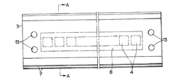
図1〜図3に示すように、照明装置1は、中心に、一対の取付基板3,3の表面にLED発光体4,4,・・を配置してなる発光部本体2を備え、該発光部本体2の両側面を透光性のカバー5,5で被覆し、LED発光体4,4,・・の光がカバー5,5を通して外方を照明するように構成されている。
Hereinafter, embodiments of the present invention will be described with reference to the drawings.
The drawings show an embodiment of a lighting device incorporating an LED light emitter according to the present invention. FIG. 1 is a perspective view of the lighting device of the present invention, and FIGS. It is a disassembled perspective view explaining the relationship between structure and components.
As shown in FIGS. 1-3, the illuminating
取付基板3は、長尺な肉薄の帯板状をなすもので、ここではアルミの押出型材が使用されている。この取付基板3は両側縁部に全長に亘ってカバー5を装着するための内向きに開口する溝形の係止部6a,6bを有する。
The mounting
上記係止部6a,6bは取付基板3の表面側に向けて立ち上がった状態に形成されて互いに溝を向き合わせており、一方の係止部6bは取付基板3の表面より高く立ち上げて外側面に複数の襞を全長に亘り突出して冷却用のフィン7を形成する。このため両側縁部の係止部6a,6bは取付基板3の表面からの高さが異なるものとなっている。
The locking
8は上記取付基板3の表面に貼り付け一体に装着したLED発光体4のためのプラスチック製の配線基板である。この基板は取付基板3の表面に沿って略全長に亘り止着され、所定の間隔で配置したLED発光体4が取付基板の表面の全域に亘って適切に配置される。
9は上記配線基板8の一端に接続した電源コードで、後述する端子カバーに植設される端子に接続される。
A
上記取付基板3は、図面における上下のものにおいて全く同一のものとなっている。ここでは押出成形したアルミ製の帯板を背面同士を向かい合わせに揃えて並べることによって一対の組としている。
2枚の取付基板3,3は図示するように両者の間に外気の出入りを可能にして冷却するための空隙10を形成する。
The mounting
As shown in the figure, the two mounting
図中11は、上記空隙10を形成するとともに、取付基板3,3同士を一体に連結固定するスペーサである。
このスペーサ11は、対の取付基板3,3の間に所定の空隙10を形成するために、必要な肉厚を以って形成してあり、一方の端部には外面側に折り返すように一対の矢形の係止片12,12を備え、この係止片12,12を各取付基板の側縁部に設ける冷却用フィン7の溝に係入させて2枚の取付基板3,3の間に収まるようにしてある。
This
スペーサ11は、ここでは長尺な取付基板3,3の両端部と長さの中間部にそれぞれ介挿して取付基板間の間隔を一定に保持すると同時に、両端部に配置するスペーサ11,11は各取付基板3,3に形成する透孔13を通して孔14を貫通する止めねじ15にナット16を締め付けることで2枚の取付基板3,3を連結し、一体化させている。
Here, the
図3は、上記スペーサ11を介しての取付基板3,3の一体化をなしたのち、この両取付基板にカバー5,5を装着する姿を示したものである。
カバー5,5は半透明の合成樹脂を材料に断面半円弧状の樋形形状に形成してあり、両側縁部には内向きに突出する突条を形成し、この突条の外側面に長さの全長に亘って外に向けて開放する溝形の掛止め部17a,17bを形成する。
FIG. 3 shows a state where the mounting
The
掛止め部17a,17bは前記取付基板3の係止部6a,6bに係合して組み合わせるもので、上記係止部6a,6bの一端にこの掛止め部17a,17bの一端を合わせて嵌め合わせたのち、係止部の長さ方向に沿ってカバー5をスライドさせることによって装着することができる。
尚、図3は、下方のカバー5を装着完了状態とし、上方のカバー5を装着途中の状態としており、両カバー5,5が完全に装着されたとき図4に示されるように全体が棒状となる発光部本体2を完成させることになる。
The latching
In FIG. 3, the
カバー5は、LED発光体4の露出を防止するもので、半透明である外、透明の場合もあり、また着色される場合もある。勿論、照明装置であることから透光性の素材を以って形成されることは言うまでもない。
The
更に、ここではカバー5を半円弧状断面形のものとしたが、この形状の選択は本発明の照明装置全体が直管状蛍光灯の形態に近似したものとなることを意図して一対のカバー5,5の組み合わせによって全体が棒状となるようにしたことによるもので、照明装置の外形状を他の形状とする場合は、このカバー5の断面形状を変更すれば容易に変えることができることになる。
Furthermore, although the
図中18は、発光部本体2の両端に端子カバー19を取り付けるための取付座部であり、20はこの取付座部18と端子カバー19との間に介挿して両者の結合を図ると共に、取付座部18に対し端子カバー19を回転可能に装着する係止ホルダーである。
In the figure, 18 is a mounting seat for attaching the
取付座部18は円盤形をなす座基板21の外側面の中心部に係止ホルダー20を装着するための軸部22を一体に有する。
この取付座部18は合成樹脂を材料に成形してあり、座基板21は前記発光部本体2の端面を覆い隠す円形に形成して内側面には前記カバー5,5の端部から入り込んでその背面に寄り添う位置決めの弧状の突条23,23を対向状に備える。
The mounting
The mounting
そして、取付座部18の外側面の周縁部には環状の壁部24を立設し、この壁部24の内周面の略半周に亘る部分に波形をなす係止爪25を形成する。この係止爪25は係止ホルダー20の回転を規制すると共に回転位置を確保するもので、これについては係止ホルダー20の動作に合せて後述する。
An
一方、取付座部18の外側面の軸部22は円筒形に形成してその中空部を座基板21を貫いて貫通孔26とすると共に軸心に沿って縦に切り込むスリット27,27を設けて分割し、このスリットを利用して縮径できるようにしている。そして軸部22の基部に環状の段28を設けると共に軸部22の先端部に外周面をテーパ状にした膨径部29を設けて軸部22の外周面に係止ホルダー20を滑合する小径な受部30を設けている。
On the other hand, the
図中31は取付座部18を発光部本体2の端面に固定するための止めねじ32を通す透孔であり、33はこの固定に当って位置決めするための突起である。
透孔31は、図4に示されるように発光部本体2の端面に表われるスペーサ11に対峙してこのスペーサ11に形成されるねじ受け孔34に向かい合わせとなり、取付座部18を発光部本体2の端面に添わせたとき、この透孔31を通して止めねじ32を上記ねじ受け孔34に揉み込んで取付座部18の取付けを完了することになる。この取付けに当って突起33をスペーサ11の空部35に突入させ、透孔31とねじ受け孔34の位置合せを行うことになる。
尚、この取付座部18の取付けに当っては前記配線基板8からの電源コード9を軸部22の貫通孔26を通して外に持ち出しておく。
In the figure,
As shown in FIG. 4, the through
For mounting the mounting
発光部本体2に対してその両端に上記取付座部18を取り付けたのち、前記係止ホルダー20を装着することになる。
係止ホルダー20は環状をなす本体部20aの外周部から外側面に向けて起立するように一対の係止片36,36を延設し、更に上記外側面から中央部の穴37を囲むように円筒形の係止部38を立ち上げている。
After the mounting
The locking
上記係止部38は前記取付座部18の軸部22に装着し係止ホルダー20を支持するもので、従って穴37と共に係止部38の中空部はこの軸部22を受け入れられる口径に形成してある。そして、この係止部38は軸心方向に沿って縦に数条のスリット39を設けて拡径することができるようにしてあり、先端部の内周面には前記軸部22の外周面に形成した環状の受部30に係入し、周方向に滑合移動することができる全体として環状をなす爪40が設けてある。
The locking
係止片36,36は端子カバー19を掛止めるためのもので、本体部20aの外周部から対立した状態で外側面側に突き出し、先端の外面側には端子カバー19に係止する爪41がそれぞれ設けてある。
この係止片36,36はキャップ状に形成される端子カバー19の内径より広い間隔を以って延設してあり、端子カバー19を装着する際は、カバーの内面に軸心方向に沿って形成する溝42,42に内側に撓めて間隔を狭めた状態で挿入し、そのまま奥に滑り込ませて最深部に形成する凹部43,43に前記爪41を掛け止めることで装着が行われる。
The locking
The locking
図16は、上記係止ホルダー20を介して取付座部18に端子カバー19を装着した状態を断面図を以って示したもので、取付座部18に対して係止ホルダー20は軸部22に向けて穴37を臨ませ、そのまま受け入れるようにして係止部38に軸部22を通し、軸部22の先端の膨径部29で爪40を一旦押し拡げて係止部38を拡張させたのち、この爪40を受部30に受け入れ、滑合させることによって組付けが行われる。そして組み付けられた係止ホルダー20は係止部38に通した軸部22を中心にして自由に回転するように装着される。
FIG. 16 is a sectional view showing a state in which the
図中44は係止ホルダー20の本体部20aの外周部から周縁方向に沿って弧状に延設された弾性爪片である。
この弾性爪片44は上記係止ホルダー20の自由な回転を規制すると共に、所定の位置で回転を止めたとき、その回転位置に停止させ、自由な回転を拘束するストッパーの働き持たせたものであり、前述した如く係止ホルダー20を軸部22に装着したとき、取付座部18の壁部24の内側に侵入させて弾性的に摺接させ、先端外側面に突設する断面山形の爪45をこの壁部の内側面に形成する前記係止爪25に噛み付かせることになる。
In the figure,
The
尚、上記係止ホルダー20は、取付座部18と同様に弾性を有し、且つ所要の剛性を有した合成樹脂を材料に成形して係止片36,36を始めとして爪40を持った係止部38、弾性爪片44は素材の弾性によって所定の範囲で撓み、復元することができるものとなっている。
The locking
上記係止ホルダー20の取付座部18に対する実際の取付けは前述したように外に向けて突き出す軸部22に向けて係止ホルダー20の穴37を押付け嵌め付けることで行われる。このとき、爪40が受部30に係合することで抜け出ることがなくなり、この受部30を案内にして自由に回転できるように装着され、また前記弾性爪片44の爪45が壁部24の係止爪25に係合することで上記自由な回転が規制されることになる。この様にして取付座部18に対して装着された係止ホルダー20に対して端子カバー19は被せるようにして押し付けることによって装着されることになる。
The actual attachment of the locking
この装着に当っては先に軸部22の貫通孔26を通して引き出した電源コード9を端子カバー19の内側に突き出す端子46,46の後端部に接続してから装着することになる。
この端子カバー19の装着は、前述したように係止ホルダー20から延設する係止片36,36の先端部に設ける爪41,41をカバー内面の溝42,42に嵌め付け、この状態で端子カバー19を係止ホルダー20に押付けることによって行われる。
For this mounting, the
As described above, the
端子カバー19の押付けによって爪41は溝42の奥に進み、凹部43,43に達したところで係止片36の復元によってこの凹部に突入係止し装着を完了することになる。
この端子カバー19が発光部本体2の両端を被う形態で装着されたとき本発明の照明装置1は完成されることになる。
図16に示したように端子カバー19は開口部側の周縁を取付座部18の座基板21の周縁部に沿った外側面に当接し、取付座部18及び係止ホルダー20の全体を被覆することになる。
When the
When the
As shown in FIG. 16, the
この様にして形成された本発明照明装置1は、蛍光灯のために準備される対峙した一対のソケット(図示せず)の間に臨ませ、両端の端子カバー19,19にそれぞれ植立する端子46,46を突き入れ接続することによって装着され使用に供されることになる。
The illuminating
この使用においては前述したように本発明照明装置1は取付基板3の表面に配置したLED発光体4・・・を光源としていることにより照明方向が取付基板3の表面方向に特定され、蛍光灯の如く全方向に照明することができないものとなっていることから、例えば自動販売機における陳列商品の照明用に使用した場合、これらの照明対象物に直ちに適切な照明光の照射ができないことが起こるが、本発明照明装置1においては、両端の端子カバー19,19が係止ホルダー20を介して発光部本体2に対して回転可能に組付くことから、前記ソケットに装着した状態で、発光部本体2を回転させ照明方向を自由に選び照明対象物に照明光を当てることができることになる。
In this use, as described above, the
この発光部本体2の回転は前記したように軸部22を中心とする係止ホルダー20の回転によって行われる。この回転において係止ホルダー20は弾性爪片44の爪45を壁部24の係止爪25を乗り越えさせ、コツコツと1爪毎に回転が進むと同時に、回転を止めた時点で爪45が壁部24の1つの係止爪25と係合することでこの係合位置で回転が止められ、これによって任意の回転、つまり照明方向の変更が止められることになる。
The rotation of the light emitting unit
尚、当該実施の形態では円形の壁部24の内周面の約半周に亘って係止爪25を波形に連設する場合を示したが、照明方向の調整は半周分の回転が得られれば充分であることから選択されたもので、例えば全周に亘って係止爪25を形成しても、また4分の1周に亘って形成してもよい。ただ回転を1回転を超えて行うと、端子46に接続するコード9が断線することもあるので、回転範囲を規制しておくことも重要である。
In this embodiment, the case where the locking
以上本発明を実施の形態に基づき説明したが、本発明照明装置2によれば、LED発光体4を光源とすることによって蛍光灯に比較して消費電力を大幅に節減できることは勿論のこと、LED発光体4に伴う光の方向性を発光部本体2の回転によって回避し、これによって蛍光灯と同等の照明装置として利用できると共に、この発光部本体2の回転操作に当っては弾性爪片44の弾性を利用してクリック感を発生させ、手による調整作業を容易にし、且つ回転を止めた位置において停止させることができることから安定的に使用することができるものとなっている。
As described above, the present invention has been described based on the embodiment. However, according to the
尚、ここでは発光部本体2の回転の規制において、係止爪25を波形に形成し、これに爪45を噛み合わせる場合につき説明したが、弾性爪片の圧接力を利用して摩擦係数を高めて摩擦力によって回転を規制するようにしてもよく、この場合には爪と爪との噛み合わせを外すことができる。
Here, the case where the locking
更に加えて本発明照明装置1は、光源とするLED発光体4から発する熱を取付基板3,3間に形成する空隙10を通して発光部本体2の外に放出する構造としたことからLED発光体4の寿命、耐用年数を延ばすことができるものとなっている。
ことにLED使用の照明装置における従来の課題はこのLEDからの発熱と、この発熱によってLED自らの寿命を短くすることにあったが、本発明は取付基板3に伝わる熱を空隙10を通して入り込む空気によって冷却し、放熱する構造としたことから自然冷却ができ、照明装置の耐用年数を大幅に改善することができるものとなっている。
In addition, the
In particular, the conventional problem in the lighting device using LEDs is to generate heat from the LEDs and to shorten the life of the LEDs by the heat generation. However, in the present invention, the air transmitted to the mounting
そして本発明においては、発光部本体2の外に向けてLED発光体4を配置する取付基板3の側縁部を露出させ、しかも、この側縁部に放熱効果を挙げるフィン7を形成する構造としたことから更に効果的に放熱できるものとなっている。
And in this invention, the structure which forms the
尚、上記空隙10についてはLED発光体4の発光量、設置個数等を勘案して任意定められると共に、取付基板3の面積、肉厚等も同様にして求める照明装置の規模等に応じて任意定められることになる。そして、実施の形態では取付基板3の一方の側縁部にのみフィン7を形成したが、これについても両側縁部に形成することを妨げるものではない。
また、本発明装置においてはLED発光体を利用する上から、適宜AC/DC変換器、電圧制御装置等を装置内に設置することになることは言うまでもない。
The
Needless to say, in the device of the present invention, an AC / DC converter, a voltage control device, and the like are appropriately installed in the device from the viewpoint of using the LED light emitter.
1 照明装置
2 発光部本体
3 取付基板
4 LED発光体
5 カバー
6a,6b 係止部
7 放熱用フィン
8 配線基板
9 電源コード
10 空隙
11 スペーサ
12 係止片
13 透孔
14 孔
15 止めねじ
16 ナット
17a,17b 掛止め部
18 取付座部
19 端子カバー
20 係止ホルダー
20a 係止ホルダーの本体部
21 取付座部の座基板
22 取付座部の軸部
23 突条
24 壁部
25 係止爪
26 貫通孔
27 スリット
28 段
29 軸部の膨径部
30 軸部の受部
31 透孔
32 止めねじ
33 突起
34 ねじ受け孔
35 空部
36 係止ホルダーの係止片
37 穴
38 係止ホルダーの係止部
39 スリット
40 爪
41 爪
42 溝
43 凹部
44 弾性爪片
45 爪
46 端子
DESCRIPTION OF
Claims (6)
前記発光部本体の両端部に、両取付基板間の端部空隙及び前記取付基板と前記カバーとの端部空隙を塞ぐ取付座部が取り付けられ、該取付座部に被さって前記LED発光体に電力を供給する端子を植立するカップ状の端子カバーが取り付けられ、全体の外形が直管状の蛍光灯型に形成されてなる、
ことを特徴とするLED発光体を内蔵した照明装置。 A pair of band-plate-shaped mounting boards assembled with a gap forming a heat radiation space open on both sides in the width direction, and a plurality of LED light emitters arranged in a distributed manner on the outer surface of each mounting board; A pair of covers attached to the outer surfaces of the pair of mounting substrates to conceal the outer surfaces and have translucency and have a part of a cylindrical surface, and a rod-shaped light emitting unit body is formed,
At both ends of the light emitting unit main body, an end gap between the two mounting substrates and a mounting seat for closing the end gap between the mounting substrate and the cover are attached, and the LED luminous body is covered with the mounting seat. A cup-shaped terminal cover for planting terminals for supplying power is attached, and the entire outer shape is formed into a straight tubular fluorescent lamp type,
An illumination device incorporating an LED light emitter.
Priority Applications (1)
| Application Number | Priority Date | Filing Date | Title |
|---|---|---|---|
| JP2008111736A JP4627088B2 (en) | 2008-04-22 | 2008-04-22 | Illumination device incorporating LED light emitter |
Applications Claiming Priority (1)
| Application Number | Priority Date | Filing Date | Title |
|---|---|---|---|
| JP2008111736A JP4627088B2 (en) | 2008-04-22 | 2008-04-22 | Illumination device incorporating LED light emitter |
Publications (2)
| Publication Number | Publication Date |
|---|---|
| JP2009266432A JP2009266432A (en) | 2009-11-12 |
| JP4627088B2 true JP4627088B2 (en) | 2011-02-09 |
Family
ID=41392034
Family Applications (1)
| Application Number | Title | Priority Date | Filing Date |
|---|---|---|---|
| JP2008111736A Expired - Fee Related JP4627088B2 (en) | 2008-04-22 | 2008-04-22 | Illumination device incorporating LED light emitter |
Country Status (1)
| Country | Link |
|---|---|
| JP (1) | JP4627088B2 (en) |
Cited By (2)
| Publication number | Priority date | Publication date | Assignee | Title |
|---|---|---|---|---|
| KR101167993B1 (en) | 2012-04-25 | 2012-07-23 | 주식회사 누리플랜 | Led floodlight |
| KR101478093B1 (en) * | 2013-04-30 | 2014-12-31 | 최치황 | Straight Pipe Type LED Lamp |
Families Citing this family (14)
| Publication number | Priority date | Publication date | Assignee | Title |
|---|---|---|---|---|
| US8500303B2 (en) * | 2008-06-17 | 2013-08-06 | Rohm Co., Ltd. | LED lamp |
| JP4740309B2 (en) * | 2008-12-03 | 2011-08-03 | 株式会社 シスコ | Light-emitting diode lamp |
| KR101076618B1 (en) | 2009-11-20 | 2011-10-27 | (주)에프엠에스 | Led lamp |
| JP5037646B2 (en) * | 2009-12-31 | 2012-10-03 | 誠一 佐藤 | Light-emitting diode lamp |
| JPWO2011087017A1 (en) * | 2010-01-16 | 2013-05-20 | 良正 陳 | LED lighting |
| KR101495580B1 (en) | 2010-04-26 | 2015-02-25 | 파나소닉 주식회사 | Leadframe, wiring board, light emitting unit, and illuminating apparatus |
| JP5031072B2 (en) * | 2010-06-28 | 2012-09-19 | 株式会社光波 | LED lamp |
| KR101448700B1 (en) | 2010-06-28 | 2014-10-10 | 파나소닉 주식회사 | Straight tube led lamp, lamp socket set, and lighting fixture |
| JP5110450B2 (en) * | 2010-08-18 | 2012-12-26 | 株式会社竹村製作所 | Holder for straight tube type LED lamp |
| JP5681428B2 (en) * | 2010-09-29 | 2015-03-11 | Idec株式会社 | Lighting device |
| JP2013065457A (en) * | 2011-09-16 | 2013-04-11 | Panasonic Corp | Lighting fixture |
| KR101128771B1 (en) | 2011-12-30 | 2012-03-23 | 주식회사 대진디엠피 | Fixed led luminators |
| JP2014029824A (en) * | 2012-07-04 | 2014-02-13 | Sankei Co Ltd | Fluorescent lamp type semiconductor lamp and sleeve parts of the same |
| KR101573032B1 (en) | 2014-02-14 | 2015-11-30 | 주식회사 린노 | Double-side emitting type led lamp |
Citations (5)
| Publication number | Priority date | Publication date | Assignee | Title |
|---|---|---|---|---|
| JPH0397580U (en) * | 1990-01-24 | 1991-10-08 | ||
| WO2003004930A1 (en) * | 2001-07-02 | 2003-01-16 | Moriyama Sangyo Kabushiki Kaisha | Display and illumination device and display and illumination system |
| JP2004302028A (en) * | 2003-03-31 | 2004-10-28 | Mitsubishi Electric Corp | Display device and guiding light device |
| JP2007257928A (en) * | 2006-03-22 | 2007-10-04 | Yashima Dengyo Co Ltd | Fluorescent lamp type led lighting tube |
| JP2008010305A (en) * | 2006-06-29 | 2008-01-17 | Nidec Sankyo Corp | Light source device and lighting system |
-
2008
- 2008-04-22 JP JP2008111736A patent/JP4627088B2/en not_active Expired - Fee Related
Patent Citations (5)
| Publication number | Priority date | Publication date | Assignee | Title |
|---|---|---|---|---|
| JPH0397580U (en) * | 1990-01-24 | 1991-10-08 | ||
| WO2003004930A1 (en) * | 2001-07-02 | 2003-01-16 | Moriyama Sangyo Kabushiki Kaisha | Display and illumination device and display and illumination system |
| JP2004302028A (en) * | 2003-03-31 | 2004-10-28 | Mitsubishi Electric Corp | Display device and guiding light device |
| JP2007257928A (en) * | 2006-03-22 | 2007-10-04 | Yashima Dengyo Co Ltd | Fluorescent lamp type led lighting tube |
| JP2008010305A (en) * | 2006-06-29 | 2008-01-17 | Nidec Sankyo Corp | Light source device and lighting system |
Cited By (2)
| Publication number | Priority date | Publication date | Assignee | Title |
|---|---|---|---|---|
| KR101167993B1 (en) | 2012-04-25 | 2012-07-23 | 주식회사 누리플랜 | Led floodlight |
| KR101478093B1 (en) * | 2013-04-30 | 2014-12-31 | 최치황 | Straight Pipe Type LED Lamp |
Also Published As
| Publication number | Publication date |
|---|---|
| JP2009266432A (en) | 2009-11-12 |
Similar Documents
| Publication | Publication Date | Title |
|---|---|---|
| JP4627088B2 (en) | Illumination device incorporating LED light emitter | |
| JP5389589B2 (en) | Light emitting diode lamp | |
| US20080211429A1 (en) | LED lamp | |
| JP5666318B2 (en) | Halogen lamp type LED lighting fixture | |
| JP5793274B1 (en) | LED lighting device | |
| US20120236565A1 (en) | Lighting device | |
| JP2010140677A (en) | Heat dissipating support for led lamp, and led lamp | |
| JP5793270B1 (en) | Auxiliary parts for mounting and lighting device | |
| JP6241611B2 (en) | Lamp device and lighting device | |
| KR200466811Y1 (en) | Fixing brakcet for lamp | |
| JP6029789B2 (en) | LED lighting device | |
| JP6334804B2 (en) | Illumination lamp, illumination lamp cover and illumination device | |
| JP5740569B2 (en) | lighting equipment | |
| JP5793268B1 (en) | LED lighting device | |
| JP2016004754A (en) | LED lighting device | |
| JP2016021405A (en) | LED lighting device | |
| KR20120111605A (en) | Led lighting apparatus provided with heat sink | |
| KR101179172B1 (en) | Fluorescent light type LED illuminator | |
| JP6293356B2 (en) | Lighting lamp and lighting device | |
| JP5820048B1 (en) | LED lighting device | |
| KR101326178B1 (en) | Illuminating apparatus | |
| JP6592785B2 (en) | Lighting lamp | |
| JP5793269B1 (en) | LED lighting device | |
| CN108779900B (en) | Lighting device | |
| JP5793273B1 (en) | LED lighting device |
Legal Events
| Date | Code | Title | Description |
|---|---|---|---|
| A977 | Report on retrieval |
Free format text: JAPANESE INTERMEDIATE CODE: A971007 Effective date: 20100917 |
|
| TRDD | Decision of grant or rejection written | ||
| A01 | Written decision to grant a patent or to grant a registration (utility model) |
Free format text: JAPANESE INTERMEDIATE CODE: A01 Effective date: 20101005 |
|
| A01 | Written decision to grant a patent or to grant a registration (utility model) |
Free format text: JAPANESE INTERMEDIATE CODE: A01 |
|
| A61 | First payment of annual fees (during grant procedure) |
Free format text: JAPANESE INTERMEDIATE CODE: A61 Effective date: 20101102 |
|
| FPAY | Renewal fee payment (event date is renewal date of database) |
Free format text: PAYMENT UNTIL: 20131119 Year of fee payment: 3 |
|
| R150 | Certificate of patent or registration of utility model |
Free format text: JAPANESE INTERMEDIATE CODE: R150 |
|
| LAPS | Cancellation because of no payment of annual fees |